WO2012157632A1 - Appareil d'évaluation d'images réelles - Google Patents
Appareil d'évaluation d'images réelles Download PDFInfo
- Publication number
- WO2012157632A1 WO2012157632A1 PCT/JP2012/062378 JP2012062378W WO2012157632A1 WO 2012157632 A1 WO2012157632 A1 WO 2012157632A1 JP 2012062378 W JP2012062378 W JP 2012062378W WO 2012157632 A1 WO2012157632 A1 WO 2012157632A1
- Authority
- WO
- WIPO (PCT)
- Prior art keywords
- plane
- image
- display panel
- aerial image
- imaging element
- Prior art date
- Legal status (The legal status is an assumption and is not a legal conclusion. Google has not performed a legal analysis and makes no representation as to the accuracy of the status listed.)
- Ceased
Links
Images




Classifications
-
- G—PHYSICS
- G02—OPTICS
- G02B—OPTICAL ELEMENTS, SYSTEMS OR APPARATUS
- G02B17/00—Systems with reflecting surfaces, with or without refracting elements
- G02B17/008—Systems specially adapted to form image relays or chained systems
Definitions
- the present invention relates to an aerial video evaluation apparatus for evaluating an aerial video.
- Patent Documents 1 to 3 an optical system that forms an image of a projection object in a space using a reflective imaging element has been proposed (for example, Patent Documents 1 to 3).
- the optical system has a reflective imaging element and a projection, and an image displayed in space (hereinafter referred to as “aerial image”) is in a plane-symmetric position with the reflective imaging element as a symmetry plane.
- the image of the projection object is formed.
- This optical system uses specular reflection of a reflective imaging element, and in principle, the ratio of the size of the image of the projection object and the image projected in space is 1: 1.
- the reflective imaging element includes an optical element that includes a plurality of holes penetrating in the thickness direction of a flat substrate and includes two mirror elements perpendicular to the inner wall of each hole (for example, a patent) 4) or a plurality of transparent cylindrical bodies protruding in the thickness direction of the substrate, and an optical element composed of two mirror elements perpendicular to the inner wall surface of each cylindrical body. (For example, refer to FIG. 7 of Patent Document 1).
- the reflective imaging element disclosed in Patent Document 1 has tens of thousands to hundreds of thousands of square holes each having a side of about 50 ⁇ m to 200 ⁇ m formed on a substrate having a thickness of 50 ⁇ m to 200 ⁇ m.
- the inner surface is mirror-coated by electroforming, nanoprinting or sputtering.
- Patent Documents 1 to 3 For the purpose of reference, the entire disclosure of Patent Documents 1 to 3 is incorporated herein by reference.
- the present inventor has made various studies on the optical system. Until now, the present inventor has mainly evaluated the display quality of aerial images visually, and has not performed a quantitative evaluation. This is because the aerial image is intangible, it is difficult to specify the position of the aerial image, and it is difficult to place the measuring device at a desired position with reference to the aerial image.
- the present invention has been made in view of the above problems, and an object thereof is to provide an aerial image evaluation apparatus capable of quantitatively evaluating an aerial image.
- An aerial image evaluation apparatus is an apparatus that evaluates an image formed in the air by a reflective imaging element, and that supports a display panel having a display surface that forms an image.
- a second support part that supports a reflective imaging element that defines an imaging symmetry plane
- a third support part that supports a light receiver having a light receiving surface, and the light emitted from the display surface of the display panel,
- the light-receiving surface receives the light constituting the aerial image formed on the imaging plane at a plane symmetric with respect to the display plane, with the imaging symmetry plane of the reflective imaging element as the symmetry plane.
- a holding mechanism for movably holding at least one of the first to third support portions.
- the aerial image evaluation device is configured to determine the position of the imaging plane based on positional information of the display surface of the display panel and positional information of the imaging symmetry plane of the reflective imaging element.
- the information processing apparatus may further include a calculation unit that obtains information, and the holding mechanism may move the third support unit according to the position information of the imaging plane.
- the aerial image evaluation device further includes a calculation unit that obtains position information of the imaging surface based on position information of the light receiving surface of the light receiver, and the holding mechanism includes the imaging The first and second support portions can be moved according to the position information of the surface.
- the holding mechanism includes the display surface, the imaging symmetry surface, and the light receiving surface so that a normal line of the imaging surface and a normal line of the light receiving surface are parallel to each other. At least one of the can be rotated.
- the embodiment of the present invention provides an aerial image evaluation apparatus capable of quantitatively evaluating an aerial image.
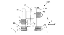
- FIG. 1 It is the typical side view of image evaluation device 100A, and is the figure seen from the Y-axis direction. It is the typical side view of image evaluation device 100A, and is the figure seen from the X-axis direction.
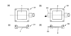
- (A)-(d) is a figure explaining the holders 31 and 32. FIG. It is a figure explaining the arrangement
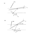
- (A) And (b) is a figure explaining the characteristic of the aerial image
- FIGS. 1 and 2 are schematic side views of the image evaluation apparatus 100A.
- a video evaluation apparatus 100A shown in FIG. 1 is an apparatus for evaluating a video (aerial video) 4 imaged in the air by the reflective imaging element 1.
- the image evaluation apparatus 100A includes a first support portion 9 that supports a display panel (for example, a liquid crystal display panel) 2 having a display surface 2a that forms an image, and a reflective imaging element 1 that defines an imaging symmetry plane 1a. It has the 2nd support part 10 which supports, and the 3rd support part 11 which supports the light receiver 3 which has the light-receiving surface 3a. Furthermore, the image evaluation apparatus 100A has a holding mechanism (in the present embodiment, the first holding mechanism 12 and the second holding mechanism) that hold at least one of the first support portion 9 to the third support portion 11 so as to be movable.
- a holding mechanism in the present embodiment, the first holding mechanism 12 and the second holding mechanism
- the image evaluation apparatus 100A is emitted from the display surface 2a of the display panel 2, and is formed on the image formation surface 4a at a position symmetrical with respect to the display surface 2a with the image formation symmetry surface 1a of the reflective image formation element 1 as a symmetry surface.
- the light constituting the imaged aerial image 4 is received by the light receiving surface 3a of the light receiver 3, and the optical evaluation of the aerial image can be performed quantitatively.
- the imaging symmetry plane 1a refers to a virtual mirror surface (corresponding to a plane-symmetric symmetry plane) that forms an image displayed on the display surface 2a at a position symmetrical with respect to the display surface 2a.
- the light receiving surface 3a of the light receiver 3 is, for example, the outermost surface of a lens included in the light receiver 3.
- the video evaluation apparatus 100 ⁇ / b> A is based on the positional information on the display surface 2 a of the display panel 2 and the positional information on the imaging symmetric surface 1 a of the reflective imaging element 1.
- a calculation unit 50 for obtaining position information is further included.
- the light receiving surface of the light receiver 3 is calculated by the calculation unit 50 based on, for example, the positional information of the display surface 2a of the display panel 2 and the positional information of the imaging symmetry plane 1a of the reflective imaging element 1.
- the arrangement position of 3a is calculated, and the third support portion 11 moves based on the calculated result.
- the video evaluation apparatus 100 ⁇ / b> A includes a horizontal base 5, and includes a first vertical pillar 21, a second vertical pillar 22, and a third vertical pillar 23 arranged on the horizontal base 5. Furthermore, the image evaluation apparatus 100A includes a first moving mechanism 15 attached to the first vertical pillar 21, a second moving mechanism 16 attached to the second vertical pillar 22, and a third attached to the third vertical pillar 23. A moving mechanism 17 is provided. The first moving mechanism 15, the second moving mechanism 16, and the third moving mechanism 17 move independently, for example, in the Y direction shown in FIG. Further, a fourth moving mechanism 18 is disposed on the first moving mechanism 15, a fifth moving mechanism 19 is disposed on the second moving mechanism 16, and a sixth moving mechanism 20 is disposed on the third moving mechanism 17.
- the fourth moving mechanism 18, the fifth moving mechanism 19, and the sixth moving mechanism 20 move independently in the X direction shown in FIG.
- the fourth moving mechanism 18 is attached to the first vertical pillar 21, the fifth moving mechanism 19 is attached to the second vertical pillar 22, and the sixth moving mechanism 20 is attached to the third vertical pillar 23.
- the first holding mechanism 12, the second holding mechanism 13, and the third holding mechanism 14 are attached to the corresponding first vertical column 21, second vertical column 22, and third vertical column 23 so as to be movable.
- At least one of the first holding mechanism 12, the second holding mechanism 13, and the third holding mechanism 14 has a rotation mechanism (rotation mechanisms 24 to 26 in the image evaluation apparatus 100A).
- the display panel 2, the reflective imaging element 1 or the light receiver 3 can be independently rotated so that the normal line of the image plane 4a and the normal line of the light receiving surface 3a are parallel to each other. With such a rotation mechanism, for example, the viewing angle characteristics of the aerial image 4 can be evaluated.
- FIG. 2 is a schematic side view of the image evaluation apparatus 100A when viewed from the X direction of FIG. However, FIG. 2 does not show the light receiver 3 and the components related to the light receiver 3 (such as the third holding mechanism 14).
- the first support portion 9 is attached to the first rotation mechanism 24, and the second support portion 10 is attached to the second rotation mechanism 25, and by these rotation mechanisms 24 and 25,
- the display panel 2 and the reflective imaging element 1 supported by the corresponding support portions 9 and 10 can rotate independently about the Y direction shown in FIG.
- the display panel 2 and the reflective imaging element 1 can be independently moved in the Y direction shown in FIG. 2 by the first moving mechanism 15 and the second moving mechanism 16, for example.
- the aerial image 4 is evaluated, the length of the display surface 2a of the display panel 2 in the Y direction is divided into two equal parts, and the axis 91 extending in the Z direction in FIG.
- the display panel 2 and the reflective imaging element 1 may be arranged so that the length is divided into two and the axis 92 extending in the Z direction in FIG.
- the display panel 2 and the reflection type imaging element 1 are arranged in this way, a large amount of light emitted from the display surface 2a of the display panel 2 is incident on the reflection type imaging element 1, which is desirable as an evaluation target.
- the aerial image can be evaluated if the display surface 2 a of the display panel 2 and the reflective imaging element 1 overlap in the Y direction. It is.
- FIG. 3 (a) and 3 (b) are schematic plan views of the holders 31 and 32, respectively, and FIGS. 3 (c) and 3 (d) are schematic views of the holders 31 and 32, respectively.
- FIG. 3 (c) and 3 (d) are schematic views of the holders 31 and 32, respectively.
- the display panel 2 and the reflective imaging element 1 are independently held by holders 31 and 32 and connected to corresponding holding mechanisms 12 and 13, respectively. It is preferred that The holders 31 and 32 can prevent the display panel 2 and the reflective imaging element 1 from being bent.
- the holder 32 is preferably provided with an opening 33. When a wiring (for example, a power supply wiring) connected to the display panel 2 is drawn downward (toward the horizontal base 5) from the opening 33, the light from the display panel 2 is not blocked by the wiring. Note that when there is no wiring connecting the display panel 2 and an external circuit, the opening 33 may not be provided.
- the reflective imaging element 1 is a reflective imaging element disclosed in Patent Document 1, for example.
- the display panel 2 is, for example, a liquid crystal display panel.
- a display panel such as an organic EL (Electro Luminescence) display panel or a plasma display can be used.
- the light receiver 3 is, for example, a luminance meter.
- a luminance meter When a luminance meter is used, the luminance of the aerial image is measured.
- a luminance meter a color luminance meter, a spectral radiance meter, or EZContrast (manufactured by ELDIM, disclosed in US Pat. No. 6,804,001) is used.
- the six moving mechanism 20 has, for example, an automatic stage driven by a stepping motor, and a control circuit (not shown) has a first holding mechanism 12, a second holding mechanism 13, a third holding mechanism 14, a first moving mechanism 15, and a second moving mechanism 20.
- the moving mechanism 16, the third moving mechanism 17, the fourth moving mechanism 18, the fifth moving mechanism 19, and the sixth moving mechanism 20 are independently controlled.
- the first rotation mechanism 24, the second rotation mechanism 25, and the third rotation mechanism 26 have, for example, an automatic rotation stage driven by a stepping motor, and a control circuit (not shown) has the first rotation mechanism 24 and the second rotation mechanism 25. , And the third rotation mechanism 26 are independently controlled.
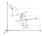
- FIG. 4 is a diagram for explaining the positional relationship among the reflective imaging element 1 (imaging symmetry plane 1a), the display panel 2 (display surface 2a), and the light receiver 3 (light receiving surface 3a).
- the calculation unit 50 in the image evaluation apparatus 100A calculates the position information of the light receiver 3 from the position information of the reflective imaging element 1 and the position information of the display panel 2 by calculation. Note that the angles ⁇ 1 to ⁇ 4 , the angle ⁇ 3 ′, the angle ⁇ 7 , and the angles ⁇ 9 to ⁇ 11 shown in FIG. 4 are each based on the horizontal plane (broken line in the figure).
- angles ⁇ 1 to ⁇ 4 , the angle ⁇ 3 ′, the angle ⁇ 7 , and the angles ⁇ 9 to ⁇ 11 have a positive direction counterclockwise and a negative direction clockwise with respect to the horizontal plane.
- the point A shown in FIG. 4 is a point on the imaging symmetry plane 1a of the reflective imaging element 1
- the point B is a point on the display surface 2a of the display panel 2
- the point C is This is a point on the image plane 4a of the aerial image 4.
- the optical characteristics (for example, luminance) of the aerial image from the direction inclined by the angle ⁇ 3 with respect to the imaging plane 4a of the aerial image 4 are evaluated.
- the angle ⁇ 3 is equal to the angle ⁇ 3 ′ formed by the direction of light emitted from the display panel 2 and the display surface 2a of the display panel 2 due to the characteristics of the reflective imaging element 1 (see FIG. 4).
- the angles formed by the horizontal plane and the reflective imaging element 1 and the display surface 2a of the display panel 2 are defined as an angle ⁇ 1 and an angle ⁇ 2 , respectively.
- the coordinates (Xa, Ya, Za) of the point A, the coordinates (Xb, Yb, Zb) of the point B, the inclination angle ⁇ 1 of the reflective imaging element 1, the inclination angle ⁇ 2 of the display panel 2 , and the angle ⁇ 3, is set in accordance with the configuration of the optical system to be evaluated.
- the coordinates of the set points A and B, and information on the angle ⁇ 1 , the angle ⁇ 2, and the angle ⁇ 3 are sent to the calculation unit (electronic computer or the like) 50.
- the reflective imaging element 1 Since the reflective imaging element 1 has the property of forming an image at a plane-symmetrical position, the angle formed by the display surface 2a of the display panel 2 and the imaging symmetric surface 1a of the reflective imaging element 1 and the imaging plane The angle formed by 4a and the imaging symmetry plane 1a of the reflective imaging element 1 is equal, and the angle ⁇ 4 satisfies the following formula (1).
- an intersection point between a straight line perpendicular to the point A and a horizontal plane including the point B is defined as a point G.
- the length d 1 of the line segment BA satisfies the following formula (2).
- d 2 is the length of the line segment AC
- angle ⁇ 7 is an angle formed by the line segment CE and the line segment CA.
- the angle ⁇ 9 is an angle formed by the horizontal plane and the line segment CA
- the angle ⁇ 10 is an angle formed by the horizontal plane and the optical axis of the light receiver 3.
- the position of the light receiver 3 for measuring the optical characteristics (for example, luminance) from the direction inclined by the angle ⁇ 3 with respect to the imaging surface 4a is obtained by calculation. Specifically, the coordinates (Xd, Yd, Zd) of the point D on the optical axis of the light receiver 3 and the installation angle ⁇ 11 of the light receiver 3 are obtained.
- Xd Xa ⁇ d 1 ⁇ sin ( ⁇ 3 + 2 ⁇ 1 ⁇ 2 ⁇ 90 °) ⁇ d 3 ⁇ cos ⁇ 180 ° ⁇ ( ⁇ 3 + 2 ⁇ 1 ⁇ 2 ) ⁇
- the optical characteristics of the aerial image 4 from the angle ⁇ 3 with respect to the imaging plane 4a can be obtained by moving the light receiver 3 accordingly. Can be evaluated.
- the optical characteristics of the aerial image 4 in the normal direction of the image plane 4a of the aerial image 4 can be evaluated.
- FIG. 5 is a schematic side view of the video evaluation apparatus 100B.
- FIG. 6A and FIG. 6B are diagrams for explaining the optical characteristics of the aerial image 4.
- FIG. 7 is a diagram for explaining the positional relationship among the reflective imaging element 1, the display panel 2, and the light receiver 3.
- the video evaluation apparatus 100B does not include the third holding mechanism 14, the third movement mechanism 17, the sixth movement mechanism 20, and the rotation mechanism 26 that the video evaluation apparatus 100A has. Therefore, the arrangement position of the light receiver 3 is fixed. Further, the target of calculation performed by the calculation unit 50 in the video evaluation apparatus 100B is different from the target of calculation performed by the calculation unit 50 in the video evaluation apparatus 100A. Specifically, in the video evaluation apparatus 100A, the calculation unit 50 calculates the position information of the light receiver 3 from the relative position information of the reflective imaging element 1 and the display panel 2 by calculation.
- the calculation unit 50 in the image evaluation apparatus 100B calculates the position information of the imaging surface 4a based on the position information of the light receiving surface 3a of the light receiver 3, and further, based on the result, the reflective imaging element 1 and the display The position information of each panel 2 is calculated.
- the first and second support portions 9 and 10 can be moved in accordance with the calculated positional information of the reflective imaging element 1 and the display panel 2.
- an angle formed between the reflective imaging element 1 and the horizontal plane is an angle ⁇ 1
- an angle formed between the display panel 2 and the horizontal plane is an angle ⁇ 2 .
- a point A is defined as an intersection point between a straight line extending perpendicularly from the point B on the display surface 2 a of the display panel 2 and the imaging symmetry plane 1 a of the reflective imaging element 1.
- the optical characteristics (for example, luminance or contrast ratio) of the aerial image 4 that is imaged in the air via the reflective imaging element 1 is a relative positional relationship between the reflective imaging element 1 and the display panel 2. That is, it is determined by the length of the line segment AB and the angle difference ( ⁇ 1 ⁇ 2 ). Therefore, the measurement results of the optical characteristics of the aerial image 4 shown in FIG. 6A and the measurement results of the optical characteristics of the aerial image 4 shown in FIG. 6B are the same in principle.
- the video evaluation apparatus 100B utilizes such characteristics.
- the arrangement position of the light receiver 3 is determined.
- the angle ⁇ 11 with respect to the coordinates (Xd, Yd, Zd) of the point D on the optical axis of the light receiver 3 and the horizontal plane (broken line) is determined.
- the point D may be the focal point of the objective lens of the light receiver 3.
- the aerial image 4 is evaluated from a direction inclined at an angle ⁇ 3 with respect to the imaging plane 4a.
- the distance d 3 between the point C and the point D on the image plane 4a is determined by the type of the light receiver 3 and the setting conditions.
- the coordinates (Xc, Yc, Zc) of the point C on the image plane 4a are obtained by geometric calculation as follows.
- the arrangement positions of the reflective imaging element 1 and the display panel 2 (the coordinates of the points A and B, the angle ⁇ 1 , the angle ⁇ 1 , so as to match the position (point C) of the imaging plane 4a obtained above.
- the angle ⁇ 2 the arrangement positions of the reflective imaging element 1 and the display panel 2 (the coordinates of the points A and B, the angle ⁇ 1 , the angle ⁇ 1 , so as to match the position (point C) of the imaging plane 4a obtained above.
- the angle ⁇ 2 the arrangement positions of the reflective imaging element 1 and the display panel 2 (the coordinates of the points A and B, the angle ⁇ 1 , the angle ⁇ 1 , so as to match the position (point C) of the imaging plane 4a obtained above.
- the angle ⁇ 2
- ⁇ 4 180 ° ⁇ 11 ⁇ 3
- the reflective imaging element 1 has a characteristic of imaging at a plane-symmetrical position, so that the length of the line segment AC is equal to the length (d 1 ) of the line segment AB.
- the coordinates (Xa, Ya, Za) of the point A on the imaging symmetry plane 1a of the reflective imaging element 1 are obtained by geometric calculation as follows.
- a point G is defined as an intersection of a straight line perpendicular to the point A and a horizontal plane including the point B.
- Za ⁇ d 1 ⁇ sin ⁇ 12 Zd ⁇ (d 3 + d 1 ) sin ⁇ 11 ⁇ d 1 ⁇ sin ( ⁇ 11 + 2 ⁇ ⁇ )
- the position information of the reflective imaging device 1 (coordinates and angle theta 1 of point A), and the position information of the display panel 2 (coordinates and angle theta 2 of the point B) is obtained.
- the optical characteristics of the aerial image 4 may be measured.
- the optical characteristics of the aerial image 4 in the normal direction of the image plane 4a of the aerial image 4 can be evaluated. Since the video evaluation apparatus 100B does not have a mechanism for moving the light receiver 3, there is an advantage that the video evaluation apparatus 100B can be manufactured at low cost.
- FIG. 8 (a) and 8 (b) show the reflective imaging element 1 (symmetrical imaging plane 1a) and display panel 2 (when the luminance measurement of the aerial video 4 is performed using the video evaluation apparatus 100A. It is a figure explaining the arrangement
- VA Vertical Alignment
- the installation angle of the liquid crystal display panel 2c is 60 °.
- the reflective imaging element 1 is disposed so as to be parallel to the horizontal plane (broken line).
- Point A is a point where a line extending in the normal direction from the center point B of the display surface 2a of the liquid crystal display panel 2c and the imaging symmetry plane 1a of the reflective imaging element 1 intersect.
- the distance between the points AB (the length of the line segment AB) is set to 90 mm, the coordinates of the point B are (0, 0, 0), and the coordinates of the point A are (45 ⁇ 3, 0, 45) ( (The unit of each coordinate is mm.)
- An intersection point between a line extending in the direction of 85 ° with respect to the display surface 2a from the center point B of the display surface 2a of the liquid crystal display panel 2c and the imaging symmetry plane 1a of the reflective imaging element 1 is a point E (the point E is For example, the distance between the points BE is set to 90 mm, the coordinates of the point B are (0, 0, 0), and the coordinates of the point E are (90 ⁇ cos 35 °, 0, 90 ⁇ ). sin 35 °).
- the brightness of the aerial image 4 measured from the normal direction of the image plane 4a of the aerial image 4 and the direction inclined by 5 ° from the normal direction of the image plane 4a of the aerial image 4 When compared with the luminance of the video 4, there is a difference in luminance of about 10%, and it can be seen that the measurement of the luminance of the aerial video 4 varies if the luminance meter 3 c is not accurately installed.
- an image evaluation apparatus capable of quantitatively evaluating an aerial image.
- the present invention is widely applied when evaluating an optical system having a reflective imaging element capable of forming an image of a projection object in space and a display panel.
Landscapes
- Physics & Mathematics (AREA)
- General Physics & Mathematics (AREA)
- Optics & Photonics (AREA)
- Testing Of Optical Devices Or Fibers (AREA)
Abstract
L'appareil d'évaluation d'images réelles (100A) d'après un mode de réalisation de la présente invention est un appareil d'évaluation d'images formées par voie aérienne au moyen d'un élément de formation d'images réfléchissant (1). Ledit appareil comprend : une première partie de support (9) qui supporte un écran d'affichage (2) comportant une surface d'affichage (2a) permettant de former des images ; une deuxième partie de support (10) qui supporte l'élément de formation d'images réfléchissant (1) qui définit un plan symétrique de formation d'images (1a) ; une troisième partie de support (11) qui supporte un photorécepteur (3) comportant une surface de réception de lumière (3a) ; et des mécanismes de maintien (12 à 14) qui maintiennent de manière mobile au moins une des parties de support parmi les première à troisième parties de support (9 à 11), de sorte qu'une lumière est émise depuis la surface d'affichage (2a) de l'écran d'affichage (2) et, au moyen du plan symétrique de formation d'images (1a) de l'élément de formation d'images réfléchissant (1) faisant office de plan symétrique, la surface de réception de lumière (3a) reçoit une lumière constituant une image réelle (4), qui est formée sur un plan de formation d'images (4a) au niveau d'une position symétrique de surface par rapport à la surface d'affichage (2a).
Applications Claiming Priority (2)
| Application Number | Priority Date | Filing Date | Title |
|---|---|---|---|
| JP2011110061 | 2011-05-17 | ||
| JP2011-110061 | 2011-05-17 |
Publications (1)
| Publication Number | Publication Date |
|---|---|
| WO2012157632A1 true WO2012157632A1 (fr) | 2012-11-22 |
Family
ID=47176949
Family Applications (1)
| Application Number | Title | Priority Date | Filing Date |
|---|---|---|---|
| PCT/JP2012/062378 Ceased WO2012157632A1 (fr) | 2011-05-17 | 2012-05-15 | Appareil d'évaluation d'images réelles |
Country Status (1)
| Country | Link |
|---|---|
| WO (1) | WO2012157632A1 (fr) |
Citations (5)
| Publication number | Priority date | Publication date | Assignee | Title |
|---|---|---|---|---|
| WO2007116639A1 (fr) * | 2006-03-23 | 2007-10-18 | National Institute Of Information And Communications Technology | Element de traitement d'image et affichage |
| JP2008158114A (ja) * | 2006-12-21 | 2008-07-10 | National Institute Of Information & Communication Technology | 光学システム |
| WO2009136578A1 (fr) * | 2008-05-09 | 2009-11-12 | パイオニア株式会社 | Appareil d'affichage d'image spatiale |
| JP2011010266A (ja) * | 2009-06-24 | 2011-01-13 | Chunghwa Picture Tubes Ltd | 立体映像ディスプレイパネルの評価方法およびシステム |
| WO2011052588A1 (fr) * | 2009-10-28 | 2011-05-05 | シャープ株式会社 | Système optique |
-
2012
- 2012-05-15 WO PCT/JP2012/062378 patent/WO2012157632A1/fr not_active Ceased
Patent Citations (5)
| Publication number | Priority date | Publication date | Assignee | Title |
|---|---|---|---|---|
| WO2007116639A1 (fr) * | 2006-03-23 | 2007-10-18 | National Institute Of Information And Communications Technology | Element de traitement d'image et affichage |
| JP2008158114A (ja) * | 2006-12-21 | 2008-07-10 | National Institute Of Information & Communication Technology | 光学システム |
| WO2009136578A1 (fr) * | 2008-05-09 | 2009-11-12 | パイオニア株式会社 | Appareil d'affichage d'image spatiale |
| JP2011010266A (ja) * | 2009-06-24 | 2011-01-13 | Chunghwa Picture Tubes Ltd | 立体映像ディスプレイパネルの評価方法およびシステム |
| WO2011052588A1 (fr) * | 2009-10-28 | 2011-05-05 | シャープ株式会社 | Système optique |
Similar Documents
| Publication | Publication Date | Title |
|---|---|---|
| TWI654445B (zh) | 空間影像顯示裝置 | |
| CN1179206C (zh) | 基片检验装置 | |
| US10775625B2 (en) | Real time algorithmic calibration and compensation of virtual and augmented reality systems and optimized semi-transparent and transparent retroreflective display systems and methods | |
| JP3955589B2 (ja) | 立体表示装置 | |
| US20110285965A1 (en) | Display device | |
| CN109581827B (zh) | 光刻投影物镜最佳焦面检测装置及方法 | |
| WO2017215397A1 (fr) | Panneau d'affichage incurvé virtuel et appareil d'affichage | |
| CN104931421A (zh) | 液晶面板视觉检测系统的定位对焦方法 | |
| CN207866469U (zh) | 杂散光测试装置 | |
| JP2019056737A (ja) | 空中映像表示装置 | |
| US20110102745A1 (en) | Stereo display apparatus | |
| JPWO2017138441A1 (ja) | マーカ | |
| WO2012157632A1 (fr) | Appareil d'évaluation d'images réelles | |
| CN101561583B (zh) | 背光模块及液晶显示装置 | |
| JP7562016B2 (ja) | 空中映像表示装置 | |
| CN100456083C (zh) | 光学部件的评价装置和评价方法 | |
| CN102707478B (zh) | 液晶板用玻璃基板和包括该玻璃基板的液晶板 | |
| KR20150116616A (ko) | 입체 영상 디스플레이의 광학 특성 측정 장치 | |
| CN104516210A (zh) | 用于光刻机镜头的远心测量装置及方法 | |
| CN108806444A (zh) | 一种磁吸式双摄像头牛顿环实验装置示教仪 | |
| JP2012225654A (ja) | レーザー墨だし装置及び該装置に用いられるレーザー墨だし器用補助具 | |
| JP2018054454A (ja) | レンズ測定装置 | |
| JP2014013319A (ja) | 光学システム | |
| JP2002181545A (ja) | 測量機用ターゲット装置 | |
| JP2012093116A (ja) | レンズ検査装置及びチャート板 |
Legal Events
| Date | Code | Title | Description |
|---|---|---|---|
| 121 | Ep: the epo has been informed by wipo that ep was designated in this application |
Ref document number: 12784875 Country of ref document: EP Kind code of ref document: A1 |
|
| NENP | Non-entry into the national phase |
Ref country code: DE |
|
| 122 | Ep: pct application non-entry in european phase |
Ref document number: 12784875 Country of ref document: EP Kind code of ref document: A1 |
|
| NENP | Non-entry into the national phase |
Ref country code: JP |