WO2012157666A1 - Dispositif d'affichage d'images avec parallaxe, procédé de génération d'images avec parallaxe et impression d'images avec parallaxe - Google Patents
Dispositif d'affichage d'images avec parallaxe, procédé de génération d'images avec parallaxe et impression d'images avec parallaxe Download PDFInfo
- Publication number
- WO2012157666A1 WO2012157666A1 PCT/JP2012/062489 JP2012062489W WO2012157666A1 WO 2012157666 A1 WO2012157666 A1 WO 2012157666A1 JP 2012062489 W JP2012062489 W JP 2012062489W WO 2012157666 A1 WO2012157666 A1 WO 2012157666A1
- Authority
- WO
- WIPO (PCT)
- Prior art keywords
- eye
- image
- parallax image
- parallax
- region
- Prior art date
- Legal status (The legal status is an assumption and is not a legal conclusion. Google has not performed a legal analysis and makes no representation as to the accuracy of the status listed.)
- Ceased
Links
Images







Classifications
-
- H—ELECTRICITY
- H04—ELECTRIC COMMUNICATION TECHNIQUE
- H04N—PICTORIAL COMMUNICATION, e.g. TELEVISION
- H04N13/00—Stereoscopic video systems; Multi-view video systems; Details thereof
- H04N13/30—Image reproducers
- H04N13/302—Image reproducers for viewing without the aid of special glasses, i.e. using autostereoscopic displays
- H04N13/317—Image reproducers for viewing without the aid of special glasses, i.e. using autostereoscopic displays using slanted parallax optics
-
- G—PHYSICS
- G02—OPTICS
- G02B—OPTICAL ELEMENTS, SYSTEMS OR APPARATUS
- G02B30/00—Optical systems or apparatus for producing three-dimensional [3D] effects, e.g. stereoscopic images
- G02B30/20—Optical systems or apparatus for producing three-dimensional [3D] effects, e.g. stereoscopic images by providing first and second parallax images to an observer's left and right eyes
- G02B30/22—Optical systems or apparatus for producing three-dimensional [3D] effects, e.g. stereoscopic images by providing first and second parallax images to an observer's left and right eyes of the stereoscopic type
- G02B30/25—Optical systems or apparatus for producing three-dimensional [3D] effects, e.g. stereoscopic images by providing first and second parallax images to an observer's left and right eyes of the stereoscopic type using polarisation techniques
-
- G—PHYSICS
- G02—OPTICS
- G02B—OPTICAL ELEMENTS, SYSTEMS OR APPARATUS
- G02B30/00—Optical systems or apparatus for producing three-dimensional [3D] effects, e.g. stereoscopic images
- G02B30/20—Optical systems or apparatus for producing three-dimensional [3D] effects, e.g. stereoscopic images by providing first and second parallax images to an observer's left and right eyes
- G02B30/26—Optical systems or apparatus for producing three-dimensional [3D] effects, e.g. stereoscopic images by providing first and second parallax images to an observer's left and right eyes of the autostereoscopic type
- G02B30/27—Optical systems or apparatus for producing three-dimensional [3D] effects, e.g. stereoscopic images by providing first and second parallax images to an observer's left and right eyes of the autostereoscopic type involving lenticular arrays
-
- G—PHYSICS
- G02—OPTICS
- G02B—OPTICAL ELEMENTS, SYSTEMS OR APPARATUS
- G02B30/00—Optical systems or apparatus for producing three-dimensional [3D] effects, e.g. stereoscopic images
- G02B30/20—Optical systems or apparatus for producing three-dimensional [3D] effects, e.g. stereoscopic images by providing first and second parallax images to an observer's left and right eyes
- G02B30/26—Optical systems or apparatus for producing three-dimensional [3D] effects, e.g. stereoscopic images by providing first and second parallax images to an observer's left and right eyes of the autostereoscopic type
- G02B30/30—Optical systems or apparatus for producing three-dimensional [3D] effects, e.g. stereoscopic images by providing first and second parallax images to an observer's left and right eyes of the autostereoscopic type involving parallax barriers
-
- G—PHYSICS
- G03—PHOTOGRAPHY; CINEMATOGRAPHY; ANALOGOUS TECHNIQUES USING WAVES OTHER THAN OPTICAL WAVES; ELECTROGRAPHY; HOLOGRAPHY
- G03B—APPARATUS OR ARRANGEMENTS FOR TAKING PHOTOGRAPHS OR FOR PROJECTING OR VIEWING THEM; APPARATUS OR ARRANGEMENTS EMPLOYING ANALOGOUS TECHNIQUES USING WAVES OTHER THAN OPTICAL WAVES; ACCESSORIES THEREFOR
- G03B35/00—Stereoscopic photography
- G03B35/18—Stereoscopic photography by simultaneous viewing
- G03B35/26—Stereoscopic photography by simultaneous viewing using polarised or coloured light separating different viewpoint images
-
- H—ELECTRICITY
- H04—ELECTRIC COMMUNICATION TECHNIQUE
- H04N—PICTORIAL COMMUNICATION, e.g. TELEVISION
- H04N13/00—Stereoscopic video systems; Multi-view video systems; Details thereof
- H04N13/10—Processing, recording or transmission of stereoscopic or multi-view image signals
- H04N13/106—Processing image signals
- H04N13/128—Adjusting depth or disparity
-
- H—ELECTRICITY
- H04—ELECTRIC COMMUNICATION TECHNIQUE
- H04N—PICTORIAL COMMUNICATION, e.g. TELEVISION
- H04N13/00—Stereoscopic video systems; Multi-view video systems; Details thereof
- H04N13/30—Image reproducers
- H04N13/332—Displays for viewing with the aid of special glasses or head-mounted displays [HMD]
- H04N13/337—Displays for viewing with the aid of special glasses or head-mounted displays [HMD] using polarisation multiplexing
Definitions
- the present invention relates to a parallax image display device, a parallax image generation method, and a parallax image print for performing stereoscopic viewing using a right-eye image and a left-eye image.
- a parallax image display device that performs stereoscopic viewing by displaying a parallax image based on a right-eye image and a left-eye image by spatially dividing a display screen by a predetermined arrangement such as a staggered arrangement or a stripe lattice arrangement, A parallax image generation method is known.
- Patent Document 1 discloses an apparatus that displays left and right parallax images by spatially dividing a display screen by a staggered arrangement or a stripe lattice arrangement.
- Patent Document 2 discloses an apparatus that displays left and right parallax images by spatially dividing a display screen by a stripe lattice arrangement.
- Patent Document 3 when a three-dimensional image is displayed and observed using a polarization control plate, a stereoscopic view region with less crosstalk is obtained by using a parallax barrier or a lenticular lens having a long opening in a predetermined direction appropriately set. Has been disclosed.
- Patent Document 4 using a parallax barrier method (parallax barrier method), image display on a display and display of an opening pattern on a spatial light modulation element are performed for each corresponding image or each corresponding scanning line.
- An apparatus is disclosed in which the crosstalk between the left and right parallax images is reduced and the flicker and moire fringes are also reduced by switching in synchronization with each other.
- a general parallax image display device divides a left-eye image and a right-eye image into a stripe grid having the same width, , A parallax image is generated so that a right-eye image is displayed in the right-eye region and a left-eye image is displayed in the left-eye region, and is displayed on the parallax image display unit.
- polarizing filters having different polarization states are installed in the right-eye image (right-eye region) and the left-eye image (left-eye region).
- the right-eye image is recognized by the right eye
- the left-eye image is recognized by the left eye, so that the brain recognizes the stereoscopic display from the right-eye image and the left-eye image having parallax. be able to.
- the above-mentioned stripe-shaped grid composed of the right-eye area and the left-eye area is almost always designed with the same pitch as the pixels to be displayed from the viewpoint of resolution, that is, expressive ability. There is no need to have a one-to-one relationship between the width and the fineness of the pixel represented in it, and humans will recognize it better if there are finer pixels in a coarse striped grid. Can do.
- the right-eye image and the left-eye image in the predetermined region and the image information of each region are equally allocated to the stripe-shaped grid without determining the importance. That's not true.
- the image signal often includes a signal component similar to the stripe grid, and the observed image often has moire.
- a stereoscopic display device that divides the display screen into a space by a predetermined arrangement and uses a polarization control plate corresponding to the space, an optimum observation height for stereoscopic vision is generated in the vertical direction of the screen, and the position is higher or lower than that.
- the crosstalk gradually increases, and finally the state of the reverse stereoscopic view is entered, and the performance of the stereoscopic display is significantly deteriorated.
- the width of the opening of the parallax barrier is narrowed, the amount of light is reduced and the image is darkened, or the information amount of the image that can be displayed is reduced by using the lenticular lens (stretched by the lenticular lens). Therefore, the pixel density in the lens power direction is reduced). Further, there is a problem that the cost is increased by the amount of the lenticular lens. Further, the apparatus of Patent Document 4 requires a means for performing interlaced scanning in correspondence with the display and the spatial light modulation element, and there is a problem that the cost is greatly increased.
- An object of the present invention is a parallax image display device that performs stereoscopic viewing by spatially dividing a display screen according to a predetermined arrangement, and does not impair the information amount of images included in each of the right-eye image and the left-eye image, and has high quality.
- a parallax image display device that generates and displays a parallax image, a parallax image generation method, and a parallax image print.
- the division size to be an optimal fineness based on the local information amount of the image to be displayed, high-quality stereoscopic viewing that does not easily generate crosstalk signals without impairing transmission of image information is possible.
- a parallax image display device that enables display, a parallax image generation method, and a parallax image print.
- the first aspect of the present invention provides an image acquisition unit that acquires a right-eye image and a left-eye image for generating a stereoscopically viewable parallax image, and information on the right-eye image
- An information amount distribution calculating unit that calculates an amount distribution and an information amount distribution of the left-eye image, and the right-eye image based on the information amount distribution of the right-eye image and the information amount distribution of the left-eye image.
- a parallax image display device comprising a parallax image generation unit that generates the parallax image from an image and the left-eye image.
- a parallax image display area configured by arranging a square reference area having at least one of a right-eye area for displaying the right-eye image and a left-eye area for displaying the left-eye image in a grid pattern.
- a first parallax image display unit wherein the parallax image generation unit includes the right-eye region for each reference region based on the information amount distribution of the right-eye image and the information amount distribution of the left-eye image. It is preferable that the parallax image is generated by assigning at least one of the left eye region and the left eye region and displaying the right eye image and the left eye image.
- the parallax image generation unit includes an information amount comparison unit, a reference area allocation unit, and an image reflection unit, and the information amount comparison unit includes the information amount distribution of the right-eye image and the left-eye image. Based on the information amount distribution, for each reference region, the information amount of the right-eye image corresponding to the reference region is compared with the information amount of the left-eye image, and a comparison result is output.
- the right eye region or the left eye region is assigned to the reference region, if any one of the information amount is larger than the other, the right eye region or the left eye region, whichever one of the information amount is larger, is assigned to the reference region,
- the right eye area and the left eye area are allocated to the reference area in half, and the image reflecting means assigns the right eye image to the right eye area and the left eye area.
- the left eye It is preferred to generate the parallax image by reflecting an image respectively.
- the parallax image generation unit includes an information amount comparison unit, a reference area allocation unit, and an image reflection unit, and the information amount comparison unit includes the information amount distribution of the right-eye image and the left-eye image. Based on the information amount distribution, for each reference region, the information amount of the right-eye image corresponding to the reference region is compared with the information amount of the left-eye image, and a comparison result is output. Assigns the right eye region and the left eye region having an area corresponding to the amount of information based on the comparison result to the reference region, and the image reflecting means assigns the right eye region to the right eye region. It is preferable that the parallax image is generated by reflecting the left-eye image in the left-eye region.
- the parallax image generation unit includes a luminance adjustment unit, and the luminance adjustment unit increases the luminance of the reference region as the allocated areas of the right eye region and the left eye region are smaller. The larger the value, the lower the brightness.
- the information amount in the reference area is the amount of harmonic signal components of the right-eye image and the left-eye image corresponding to the reference area, the right-eye image and the left-eye image corresponding to the reference area.
- the variance value of the luminance distribution of the right-eye image and the left-eye image corresponding to the reference region, and the difference amount between the pixel values of the right-eye image and the left-eye image corresponding to the reference region At least one is preferred.
- the reference area is composed of at least four pixels.
- a polarization filter is provided on the front surface of the first parallax image display unit and can be operated based on the parallax image so that the polarization state of the left-eye region and the polarization state of the right-eye region are different. It is preferable.
- the first parallax image display unit is installed in front of the first parallax image display unit, and based on the parallax image, with respect to an observer away from the first parallax image display unit by a predetermined interval, It is preferable to provide a two-layer parallax barrier operable to transmit only light from the left-eye region and transmit only light from the right-eye region in the right eye direction of the observer.
- the present invention calculates the information distribution of the right-eye image and the left-eye image used for stereoscopic display, respectively, and in the parallax image display area configured by arranging square reference areas in a grid pattern, Based on the information amount distribution of the right eye image and the information amount distribution of the left eye image, a right eye region for displaying the right eye image and a left eye region for displaying the left eye image for each reference region. And a parallax image is generated by reflecting the right-eye image in the right-eye region and the left-eye image in the left-eye region. .
- the information amount in the reference region is compared for each reference region, and the right eye image and the left eye image are compared.
- the larger one of the right eye region and the left eye region is assigned to the reference region, and the information amount is substantially the same.
- the right eye region and the left eye region are allocated in half each.
- the information amount in the reference region is compared for each reference region, and the right eye image and the left eye image are compared.
- the right eye region and the left eye region are respectively assigned to the reference region according to the size of the information amount, and when the information amount is substantially the same, the right eye region and the left eye region Are preferably assigned to the reference area in half.
- the luminance is increased as the allocated areas of the right eye area and the left eye area are smaller, and the luminance is decreased as the area is larger.
- the present invention also provides a parallax image print characterized in that the parallax image generated by the above-described parallax image generation method is printed.
- polarizing films having different polarization states are attached to the right eye region and the left eye region.
- the light from the left eye region is placed in the direction of the left eye of the observer based on the parallax image with respect to an observer installed in front of the parallax image print and separated from the parallax image print by a predetermined interval. It is preferable to provide a two-layer parallax barrier film that transmits and transmits only the light from the right eye region in the right eye direction of the observer.
- the second aspect of the present invention further includes a second parallax image having a parallax image display area including a right-eye area for displaying the right-eye image and a left-eye area for displaying the left-eye image.
- a display unit wherein the parallax image generation unit includes a parallax image display region classification unit and a region division unit, and the parallax image display region classification unit displays the parallax image display region based on the information amount distribution.
- the area dividing means divides the partial display area into unit area sets each having the same shape of right-eye unit area and left-eye unit area having different sizes for each classification
- the parallax image generation unit displays the right-eye image in the right-eye region configured by the right-eye unit region, and the left-eye image is displayed in the left-eye region configured by the left-eye unit region. It is to provide a parallax image display device and generates the parallax image by displaying.
- the information amount of the information amount distribution includes the fineness of the image (the amount of change in the pixel value), the amount of the high-frequency signal component that the image has, the maximum frequency value that the image has, the variance value of the luminance distribution, It is preferable that the difference amount is at least one pixel value between the image and the left-eye image.
- the area dividing means divides the partial display area by a smaller unit area set as the information amount is larger, and as a smaller unit area set as the information amount is smaller.
- the unit area set is preferably in a stripe lattice shape.
- the area dividing unit determines a division direction of the partial display area according to a shape of the partial display area.
- a polarization filter is provided on the front surface of the second parallax image display unit and operable to change the polarization state of the left-eye region and the polarization state of the right-eye region based on the parallax image. It is preferable.
- a parallax barrier that can be operated so as to transmit only light from the left-eye region and transmit only light from the right-eye region in the right eye direction of the observer.
- the present invention calculates the information amount distribution of the right-eye image and the left-eye image for generating a stereoscopically viewable parallax image, and displays the parallax image based on the information amount distribution.
- the display area is classified into a plurality of partial display areas, and each of the partial display areas is divided into unit area sets each including a right-eye unit area and a left-eye unit area having different sizes for each classification,
- a parallax image generation method is provided, wherein a parallax image is generated by displaying the right-eye image and the left-eye image in the right-eye unit region and the left-eye unit region, respectively.
- the information amount of the information amount distribution includes the fineness of the image (the amount of change in the pixel value), the amount of the high-frequency signal component that the image has, the maximum frequency value that the image has, the variance value of the luminance distribution, It is preferable that the difference amount is at least one between the image and the left-eye image.
- the partial display area is divided into smaller unit area sets as the information amount is larger, and is divided into larger unit area sets as the information amount is smaller.
- the unit area set preferably has a stripe lattice shape.
- the division direction of the partial display area is determined according to the shape of the partial display area.
- the present invention also provides a parallax image print characterized in that the parallax image generated by the above-described parallax image generation method is printed.
- polarizing films having different polarization states are attached to the right eye region and the left eye region.
- the light from the left eye region is placed in the direction of the left eye of the observer based on the parallax image with respect to an observer installed in front of the parallax image print and separated from the parallax image print by a predetermined interval. It is preferable to provide a parallax barrier film that transmits and transmits only light from the right eye region in the right eye direction of the observer.
- a parallax image display device a parallax image generation method, and a parallax image that generate and display a high-quality parallax image that maximizes the amount of information transmitted between the right-eye image and the left-eye image.
- Prints can be provided.
- FIG. 1 It is an external view which shows one Example of the parallax image display apparatus which concerns on the 1st aspect of this invention.
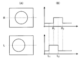
- FIG. 1 It is a block diagram which shows the detailed structure of one Example of the parallax image display apparatus of FIG. (A) is an example of a right-eye image and a left-eye image
- (B) is a case where the dotted line position shown in (A) is the horizontal axis and the information amount of the right-eye image and the left-eye image is the vertical axis.
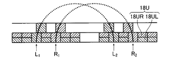
- FIG. 6C is an explanatory diagram of a two-layer parallax barrier according to the present invention.
- FIG. 2 is an external view illustrating an example of a first parallax image display unit when a parallax barrier method is used in the parallax image display device illustrated in FIG. 1.
- FIG. 5 is an explanatory diagram when a stripe direction is set to a vertical direction in a space-divided parallax image display including a right-eye image and a left-eye image shown in FIG.
- FIG. 20 is an explanatory diagram when the partial display area in FIG. 19 is divided into unit area sets having different sizes (vertical stripe lattices having different widths) according to classification in the parallax barrier method.
- a parallax image display device, a parallax image generation method, and a parallax image print according to the present invention will be described below in detail based on preferred embodiments shown in the accompanying drawings.
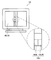
- FIG. 1 is an external view of an embodiment showing a configuration of a parallax image display device according to a first aspect of the present invention.
- the parallax image display device 10 of the present invention includes a first parallax image display unit 12, polarized glasses 14, an operation input unit 16, a console 20, and an image server 32.
- the first parallax image display unit 12 that displays a space-divided parallax image has a parallax image display region 18 configured by a square reference region 18U.
- the reference area 18U includes at least one of a right-eye unit area 18UR that displays a right-eye image and a left-eye unit area 18UL that displays a left-eye image. Therefore, the first parallax image display unit 12 includes a left-eye region (left-eye image display) configured by a right-eye region (right-eye image display region) 18R configured by the right-eye unit region 18UR and a left-eye unit region 18UL.
- a parallax image display area 18 composed of a reference area 18U.
- the first parallax image display unit 12 includes a polarizing filter 48 that can manipulate the polarization state of an arbitrary region, and a right-eye image is displayed in the parallax image display region 18 of the first parallax image display unit 12.
- the polarizing filter 48 is operated so that the polarization state of the portion (right eye region 18R) and the portion where the left eye image is displayed (left eye region 18L) is different.
- a liquid crystal panel that independently operates the polarization state of the parallax image, which is different from the liquid crystal display for displaying the parallax image, can be considered.
- a polarization filter using a liquid crystal panel is installed in front of a liquid crystal display that displays a parallax image, and operates the polarization states of the left-eye region 18L and the right-eye region 18R of the parallax image using information on the parallax image, respectively. be able to.
- the observer views the parallax image displayed on the first parallax image display unit 12 using the polarizing glasses 14 so that the left eye recognizes only the image for the left eye through the polarizing lens 14L, and the right eye has the polarizing lens. Only the image for the right eye is recognized through 14R. Thereby, the observer's brain can perform stereoscopic viewing based on the left-eye image recognized by the left eye and the right-eye image recognized by the right eye.
- the operation input unit 16 issues various instructions to the control unit 26 (to be described later) of the console 20. For example, an instruction to acquire a right-eye image and a left-eye image from the image server 32, switching between stereoscopic display and planar display in the first parallax image display unit 12, storage of the generated parallax image in the image server 32, etc. Instructions are given.
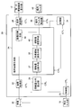
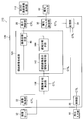
- FIG. 2 is a block diagram showing the detailed configuration of the parallax image display device of the present invention, and particularly shows the detailed configuration of the console 20.
- the console 20 includes an image acquisition unit 22, a parallax image generation unit 24, a control unit 26, a display control unit 28, a polarization filter control unit 30, a storage unit 34, and an information amount.
- the above-described parallax image generation unit 24 includes an information amount comparison unit 37, a reference area allocation unit 38, a luminance value adjustment unit 40, and an image reflection unit 46.
- the console 20 is specifically configured by a computer including a CPU (Central Processing Unit), a RAM (Main Storage Device), a hard disk, and the like. In practice, the above-described CPU (Central Processing Unit), RAM The (main storage device), the hard disk, and the like are linked to constitute the above-described units and units in the console 20.
- the image acquisition unit 22 is controlled through the control unit 26 according to an instruction from the instruction input unit 16 and acquires the right-eye image and the left-eye image that are stereoscopically stored and stored in the image server 32.
- the information amount distribution calculation unit 36 calculates the information amount distribution of each image in the right eye image and the left eye image acquired by the image acquisition unit 22, and calculates the calculated information amount distribution of the right eye image and the left eye image. Is output to the parallax image generation unit 24.
- the information amount is, for example, (1) the amount of harmonic signal components of the image, (2) the value of the maximum frequency of the image, (3) the variance value of the luminance distribution of the image in the local region, (4 ) The amount of difference between the pixel values of the left and right original images.
- the parallax image generation unit 24 reflects the right-eye image and the left-eye image in the right-eye region 18R and the left-eye region 18L, and generates the above-described parallax image.
- the parallax image generation unit 24 compares the information amount of the corresponding right-eye image and the information amount of the left-eye image for each reference region 18U constituting the parallax image display region 18 by the information amount comparison unit 37.
- the reference region 18U may be composed of, for example, 4 ⁇ 4 16 pixels or 6 ⁇ 6 36 pixels.
- the size of the reference area is the size of the display image (number of pixels) or the parallax image display area 18 (corresponding to the parallax image display area 18 on a one-to-one basis). It may be changed according to the size (resolution).
- information in the reference area 18U is calculated based on the information amount distribution of the right eye image and the information amount distribution of the left eye image calculated by the information amount distribution calculating unit 36. Compare the amount.
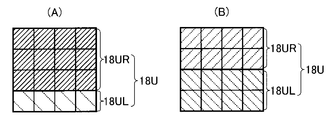
- the reference area assigning means 38 assigns the right-eye unit area 18UR and the left-eye unit area 18UL to the reference area 18 based on the amount of information. For example, one of the right-eye unit area 18UR and the left-eye unit area 18UL having a large information amount may be assigned. When the information amount is approximately the same, the right-eye unit area 18UR and the left-eye unit area 18UL are allocated. Both of them may be assigned in half. Further, the area areas of the right-eye unit area 18UR and the left-eye unit area 18UL may be changed and assigned according to the amount of information.
- the reference area 18U when the reference area 18U is 4 ⁇ 4 16 pixels, it may be allocated as 12 pixels of the right eye unit area 18UR4 ⁇ 3 and 4 pixels of the left eye area 18UR4 ⁇ 1 depending on the amount of information.
- the luminance value may be adjusted according to the area area. The smaller the area, the darker the area will be if the brightness value is not changed, so the brightness value needs to be increased. For the opposite reason, the luminance value needs to be lowered as the area of the region increases.
- the image reflecting means 46 combines the right-eye image and the left-eye image so that the right-eye image is displayed in the right-eye unit region 18UR and the left-eye image is displayed in the left-eye unit region 18UL for each reference region 18U.
- a parallax image is generated by reflecting.
- the control unit 26 receives an instruction from the instruction input unit 16 and controls the operation of each unit of the parallax image display device 10.
- the image acquisition unit 22 acquires the left-eye image and the right-eye image
- the parallax image generation unit 24 generates the parallax image
- the first parallax image display unit 12 performs the display control unit 28 described later.
- a parallax image is displayed, and the polarization filter control unit 30 (to be described later) controls the polarization state of the polarization filter 48 installed on the first parallax image display unit 12 (not shown) according to the parallax image.
- the generated parallax image may be stored in the storage unit 34 described later, and the generated parallax image may be stored in the image server through the storage unit 34.
- the display control unit 28 displays the left-eye image and the right eye on the first parallax image display unit 12 according to an instruction from the instruction input unit 16. The image is displayed in plane.
- the polarization filter control unit 30 controls the polarization filter 48 so that the left-eye region 18L and the right-eye region 18R are filtered with different polarization states. To do.
- the storage unit 34 temporarily stores the parallax image generated by the parallax image generation unit 24 together with the left-eye image and the right-eye image, and stores image data of these images in the image server 32 according to an instruction from the instruction input unit 16. save.
- the console 20 generates a parallax image based on the left-eye image and the right-eye image that can be stereoscopically viewed as described above.
- the generated parallax image is displayed on the first parallax image display unit 12 having the parallax image display area 18 including the left-eye area 18L and the right-eye area 18R, and is stored in the image server 32 as necessary.
- the image server 32 only needs to be able to store a left-eye image and a right-eye image that can be stereoscopically viewed as image data.
- the image server 32 is not limited to the image server, and instead, the image data of the left-eye image and the right-eye image is stored.
- Various stored recording media and recording medium reading means can be used.
- the image acquisition unit 22 Upon receiving an instruction from the instruction input unit 16, the image acquisition unit 22 acquires a right-eye image R and a left-eye image L that are stereoscopically viewable as shown in FIG.
- the acquired right-eye image R and left-eye image L are output to the information amount distribution calculation unit 36, and the information amount distribution of the right-eye image R and the information amount distribution of the left-eye image L are calculated.
- the information amount for example, the amount of the harmonic signal component of (1) image described above is used.
- the information amount distribution of the right-eye image R and the information amount distribution of the left-eye image L calculated by the information amount distribution calculation unit 36 are obtained by the information amount comparison unit 37 of the parallax image generation unit 24 as shown in FIG.
- the amount of information is compared for each corresponding reference area 18U, and the comparison result is output.
- the information amount of the right eye image R or the information amount of the left eye image L is larger in the corresponding reference area 18U, and how much is larger.
- the reference area allocating means 38 allocates the right-eye unit area 18UR and the left-eye unit area 18UL to the reference area 18U based on the comparison result described above, as shown in FIG.
- the allocation of the right-eye unit area 18UR and the left-eye unit area 18UL as shown in FIG. 6A, either the right-eye unit area 18UR or the left-eye unit area 18UL may be allocated. If they are about the same, half may be allocated. Further, as shown in FIG. 6B, the area areas of the right-eye unit area 18UR and the left-eye unit area 18UL may be changed according to the amount of information.
- the luminance value may be adjusted by using the luminance value adjusting means 40 in accordance with the allocated area area. If the area of the area is small, the luminance value is increased (lightened), and if the area of the area is large, the luminance value is decreased (darkened).
- the image reflecting means 46 generates a parallax image by reflecting the right-eye image R in the right-eye unit region 18UR and reflecting the left-eye image L in the left-eye unit region 18UL.
- the parallax image generated by the parallax image generation unit 24 is displayed on the first parallax image display unit 12 through the display control unit 28, temporarily stored in the storage unit 34, and from the instruction input unit 16. May be stored in the image server 32.
- the polarization filter control unit 30 obtains information on the parallax image display region 18 in which the right-eye unit region 18UR and the left-eye region 18UL are allocated for each reference region and the luminance value is adjusted, and controls the polarization filter 48. .
- the polarization filter 48 is controlled so that the polarization state is different between the right eye region 18R and the left eye region 18L of the parallax image display region 18, and corresponds to the filter portion corresponding to the right eye region 18R and the left eye region 18L. Light having a different polarization state is transmitted from the filter portion.
- the observer can perform a stereoscopic view by observing the parallax image displayed on the first parallax image display unit 12 through the polarizing glasses 14 by the parallax image display device 10 of the present invention.
- the above is the operation of the parallax image display device 10 according to the first aspect of the present invention.
- the parallax image generation unit 24 generates a parallax image using the parallax image generation method of the present invention, and displays the parallax image on the first parallax image display unit 12.
- 3A and 3B show that the edge portions on the circular dotted line represented by the right-eye image R and the left-eye image L are R1 and R2, and L1 and L2.
- the parallax image generation method in order to generate the parallax image so as not to impair image information of the right-eye image and the left-eye image as much as possible, the right-eye image R in FIG.
- the right-eye image R and the left-eye image for those edge portions that is, the portions R1, R2, and L1, L2 in FIG. L only needs to be emphasized.
- the information on the right-eye image R is prioritized, and the right-eye image R is preferentially displayed in the reference area 18U. It is preferred that Further, in the parallax image, in the area where the edge portions L1 and L2 of the left-eye image L are displayed, the information on the left-eye image L is given priority, and the left-eye image L is displayed in the reference area 18U with priority. Is preferred.
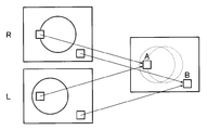
- the right-eye image R, the left-eye image L, and the information amount distribution of the image are calculated by the information amount distribution calculating unit 36, and the right-eye image R is calculated from the calculated information amount distribution as shown in FIG.
- the information amount comparison means 37 By calculating the information amount in the same region (the same reference region 18U) of the image R and the left-eye image L and comparing them by the information amount comparison means 37, the image with the larger information amount in the parallax image is given priority. Display.
- the information amount is, for example, as described above, (1) the amount of harmonic signal components of the image, (2) the value of the maximum frequency of the image, and (3) the distribution of the luminance distribution of the image within the local region. Value, and (4) the difference between the pixel values of the left and right original images.
- the right eye image R and the left eye image L are compared in the same reference area 18U, and the information amount is larger.
- either one of the image R for the right eye and the image L for the left eye may be displayed as a parallax image in the reference area 18U. They may be displayed side by side.
- the reference area allocating unit 38 increases the allocation area of the image having the larger information amount, thereby reducing the information amount.
- the allocated area of the image may be reduced. For example, if the right eye image R and the left eye image L have a large amount of information in the right eye image R, the allocated area of the left eye image L is increased accordingly.
- FIG. 6B there is no case where the image information is not reflected in the parallax image as in FIG. 6A, but the allocated area of one image is reduced, so that one image is viewed through the polarizing glasses. In this case, a portion where the image is displayed darkly is formed. Therefore, even if the allocated area is reduced, it is necessary to adjust the parallax image so that the image does not become dark.
- the right eye image R and the left eye image L are assigned to the reference area 18U as shown in FIG. 6C, so that each reference area 18U of the right eye image and the left eye image is assigned.
- the light amounts of the right eye unit region 18UR and the left eye unit region 18UL in the reference region 18U can be made uniform, and the light amounts of the right eye image R and the left eye image L can be kept constant. Can be aligned.
- the reference region 18U shown in FIG. 5A is obtained by the information amount comparing means 37 between the right eye image R and the left eye image L.
- the amounts are compared, priority is given to the right-eye image R in which the edge portion of the circular figure enters the reference region 18U.
- the reference area allocating unit 38 determines the amount of information.
- the right-eye unit area 18UR is assigned 12 squares to display the right-eye image R having a large size
- the left-eye unit area 18UL is assigned 4 squares to display the left-eye image L having a small information amount.
- the edge portion of the circular figure, which is the right eye image R is displayed with the brightness value slightly lowered by the brightness value adjusting means 40
- the left eye image area L is displayed in the left eye unit area 18UL. Is displayed with the brightness increased.
- the reference area 18U shown in FIG. 5B displays nothing in both images when the information amount of the right eye image R and the left eye image L is compared. Therefore, the right eye image R and the left eye image L are equally allocated.
- the parallax image display device 10 acquires the right-eye image R and the left-eye image L taken for stereoscopic display through the parallax image generation unit 24 from an image server (not shown) or the like (step S1).
- the parallax image generation unit 24 calculates the information amount distribution in each of the right-eye image R and the left-eye image L (step S3). For example, (1) the amount of harmonic signal components of the image, (2) the value of the maximum frequency of the image, (3) the variance value of the luminance distribution of the image within the local area, and (4) the pixels of the left and right original images
- the information amount distribution is calculated using at least one of the difference amounts of values as the information amount.
- the parallax image generation unit 24 divides the parallax image display area into square local areas, for example, and compares any of the information amounts (1) to (4) within these local areas. Then, as shown in FIG. 6C, the display ratio of the reference region 18U between the right-eye image R and the left-eye image L is determined based on the comparison result (step S5).
- the right-eye image R may be displayed at 4 and the left-eye image L may be displayed at 1 ⁇ 4 from the bottom.
- the left-eye image L that is 1 ⁇ 4 from the bottom is displayed with an increased luminance value
- the right-eye image R that is 3 ⁇ 4 from the top is displayed with a decreased luminance value.
- the amount of information is compared for all the reference areas 18U on the parallax image display area 18, and a parallax image is generated (step S7).
- the displayed space-divided parallax image can be said to be a parallax image in which the information amount of each of the right-eye image and the left-eye image is kept to the maximum.
- the generated parallax image is displayed on the first parallax image display unit 12 having the parallax image display region 18 (the parallax image display region 18 and the display screen correspond one-to-one).
- Step S9 the parallax images may be displayed not only on the first parallax image display unit 12 but also by an output device such as a printer. This is because the present invention is a space division type stereoscopic display and does not require electrical drive.
- parallax image print As described above, the parallax image generated by the parallax image generation method is not only displayed on the first parallax image display unit 12 of the parallax image display device 10 described above, but also printed on paper by a printer or the like (not shown). Also, it can be a parallax image print.
- a polarizing film corresponding to the left-eye region 18L and the right-eye region 18R of the parallax image is further pasted on the parallax image.
- a polarizing film corresponding to the left-eye region 18L and the right-eye region 18R of the parallax image is further pasted on the parallax image.
- an elliptically polarizing plate described in JP 2009-193014 A can be used as the polarizing film. Since the above-described elliptically polarizing plate can be manufactured by arbitrarily changing the polarization pattern, the above-described elliptically polarizing plate whose polarization pattern corresponds to the left-eye region 18L and the right-eye region 18R is manufactured and parallax is used as a polarizing film. Just paste it on the image.
- the observer uses the polarizing glasses 14 to see the parallax image print to which the above-described polarizing film is attached, so that the right eye recognizes only the right-eye image through the polarizing lens 14R and the left eye through the polarizing lens 14L. Since only the left-eye image is recognized, stereoscopic viewing can be performed based on these as described above.
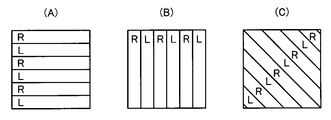
- the dividing direction of the striped lattice of the parallax image is not limited to the horizontal (horizontal) direction shown in FIGS. 1, 4, 6, and 7. Since the left eye image is recognized by the observer's left eye and the right eye image is recognized by the observer's right eye, the observer displays stereoscopically in any direction such as the vertical (vertical) direction and the oblique direction. be able to.
- the first parallax image display unit 12 may include a two-layer parallax barrier 49 described later instead of the polarizing filter 48.
- the parallax image is limited to the parallax image divided in a stripe lattice shape in the vertical direction shown in FIG. 9B (direction perpendicular to the eyes of the observer).
- a parallax barrier control unit 31 that controls the two-layer parallax barrier 49 according to the parallax image (parallax image display region 18) generated by the parallax image generation unit 24 is provided.
- the polarizing glasses 14 are not necessary, and stereoscopic vision can be performed with the naked eye.
- the parallax barrier As the parallax barrier, a switch liquid crystal or the like that can electrically switch the presence or absence of light transmission in an arbitrary area in pixel units is considered, and the two-layer parallax barrier 49 is also configured by stacking two layers of switch liquid crystals.
- the parallax barrier control unit 31 controls the two-layer parallax barrier 49 by electrically controlling the two layers of switch liquid crystal.
- the conventional parallax barrier 50 is arranged at a certain distance from the front surface of the first parallax image display unit 12 so that the right-eye image is observed by the right eye, as shown in FIG. Since the left-eye image is observed, the observer can perform a stereoscopic view using the right-eye image and the left-eye image. In this case, as shown in FIG. 10A, the display area (information amount) of the right-eye image and the display area of the left-eye image are substantially the same.
- the shape of the observed right-eye area 18R is changed when the space division interval of the parallax image is changed for each predetermined area.
- the shape of the left eye region 18L is different from that of the left eye region 18L, it is necessary to change the thickness and shape of the parallax barrier as shown in FIG.
- the two-layer parallax barrier 49 according to the present invention combines two layers of the conventional parallax barrier 50 shown in FIG.
- the same effect as a parallax barrier having a complicated shape can be obtained, and a parallax barrier having an arbitrary shape can be formed according to a parallax image (parallax image display region 18).
- the two-layer parallax barrier 49 includes a first layer 49A and a second layer 49B.
- the right eye unit in the reference region 18U according to the present invention is limited by the first layer 49A and the second layer 49B restricting light from a part of the right eye image R1 to R5 (right eye unit region 18UR).
- the display area (area observed by the observer) of the area 18UR and the left-eye unit area 18UL can be arbitrarily changed.
- the parallax image display device 10 of the present invention includes the above-described two-layer parallax barrier 49 on the front surface of the first parallax image display unit 12, and stripes in the vertical direction by the parallax image generation unit 24.
- the parallax image divided in a lattice shape is generated, the right eye image of the parallax image is observed by the right eye of the observer with respect to the observer away from the first parallax image display unit 12 by the observer.
- the two-layer parallax barrier 49 is operated so that the left-eye image of the parallax image is observed by the left eye. Therefore, the observer can perform autostereoscopic vision based on the left-eye image and the right-eye image by recognizing the right-eye image with the right eye and the left-eye image with the left eye.
- the parallax image is limited to the vertical stripe grid as described above, and thus is not a parallax image divided into the horizontal stripe grid shown in FIG. As shown in FIG. 12, a parallax image divided into vertical stripe lattices is generated.
- the parallax images are classified as shown in FIG. 13 corresponding to FIG. 6 by comparing the amount of information, specifically, FIG. 14 (A) corresponding to FIG. 7 (A) and FIG. 7 (B). ) And (B).
- the difference in display area between the right-eye unit area 18UR and the left-eye unit area 18UL in the reference area 18U in FIG. 14A is created by the above-described two-layer parallax barrier 49.
- a two-layer parallax barrier film can be used instead of the polarizing film. Similar to the two-layer parallax barrier described above, the two-layer parallax barrier film is formed by stacking two layers of parallax barrier films. In this case as well, the polarizing glasses 14 are not necessary, and stereoscopic vision can be performed with the naked eye, as described above.
- the parallax barrier film for example, a combination of a light-impermeable film that does not transmit light and a light-transmitting film that transmits light can be considered.
- a two-layer parallax barrier film configured according to the parallax image is installed (pasted) on the front surface of the parallax image print (that is, two parallax barrier films configured according to the parallax image are spaced at a predetermined interval).
- the right eye image is observed by the observer's right eye
- the left eye image is observed by the observer's left eye.
- the autostereoscopic viewing can be performed based on the right-eye image and the left-eye image.
- FIG. 15 is an external view of an embodiment showing a configuration of a parallax image display device according to a second aspect of the present invention.
- the parallax image display device 110 of the present invention includes a second parallax image display unit 112, polarized glasses 14, an operation input unit 16, a console 120, and an image server 32.
- the polarized glasses 14, the operation input unit 16, and the image server 32 described above have the same configurations as those in the first aspect, and thus description thereof is omitted.
- the second parallax image display unit 112 that displays a space-divided parallax image displays a right-eye region (right-eye image display region) 118 ⁇ / b> R that displays a right-eye image and a left-eye image.
- the right eye region 118R is constituted by a right eye unit region 118UR
- the left eye region 118L is constituted by a left eye unit region 118UL.
- the pair of right eye unit areas 118UR and left eye unit areas 118UL constitutes a unit area set 118U.
- As the unit region set 118U for example, a stripe lattice shape can be considered as shown in FIG. Of course, various shapes such as a staggered lattice and a square lattice may be used.
- the second parallax image display unit 112 includes a polarizing filter 48 that can manipulate the polarization state of an arbitrary region as in the first mode.
- a polarizing filter 48 that can manipulate the polarization state of an arbitrary region as in the first mode.
- the parallax image as in the first mode, the right-eye image is displayed.
- the polarizing filter 48 is operated so that the polarization state is different between the portion (right-eye region 118R) where is displayed and the portion (left-eye region 118L) where the left-eye image is displayed.
- FIG. 16 is a block diagram showing a detailed configuration of the parallax image display device according to the second aspect of the present invention, and particularly shows a detailed configuration of the console 120.
- the console 120 described above includes an image acquisition unit 22, a parallax image generation unit 124, a control unit 26, a display control unit 28, a polarization filter control unit 30, a storage unit 34, and an information amount.
- the parallax image generation unit 124 includes a parallax image display region classification unit 142, a region division unit 144, and an image reflection unit 46.
- the console 120 is specifically configured by a computer including a CPU (Central Processing Unit), a RAM (Main Storage Device), a hard disk, and the like.
- a CPU central processing unit
- a RAM main storage device
- a hard disk and the like are linked to constitute the above-described units and units in the console 120.
- the information amount distribution calculation unit 136 calculates the information amount distribution of each image in the right eye image and the left eye image acquired by the image acquisition unit 22, and calculates the calculated information amount distribution of the right eye image and the left eye image. Is output to the parallax image generation unit 124.
- the information amount is, for example, (1) the amount of harmonic signal components of the image, (2) the value of the maximum frequency of the image, (3) the variance value of the luminance distribution of the image in the local region, (4 ) The amount of difference between the pixel values of the left and right original images.
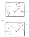
- the information amount distribution is calculated by the information amount distribution calculating unit 136 in the right-eye image in FIG. 17A and the left-eye image in FIG. 17B.
- the information amount for example, the information amount distribution is calculated on the basis of the amount of the harmonic signal component of the above-mentioned (1) image.
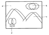
- the right-eye image and the left-eye image are composed of, for example, (a) sky, (b) clouds, (c) mountains, (d) trees, and the like.
- the parallax image generation unit 124 reflects the right-eye image and the left-eye image in the right-eye region 118R and the left-eye region 118L, and generates the above-described parallax image.
- the parallax image generation unit 124 uses the parallax image display region classification unit 142 based on the information amount distribution of the right-eye image and the information amount distribution of the left-eye image calculated by the information amount distribution calculation unit 136 described above.
- the parallax images are classified into a plurality of partial display areas 118D.
- the parallax image is an image in which the right-eye image and the left-eye image are displayed so as to overlap each other (displayed by being divided into spaces). There are parts that differ greatly from each other and parts that are substantially similar.
- the information on the edge portions (a) to (d) is important for performing highly accurate stereoscopic viewing.
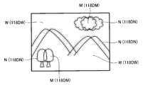
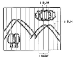
- the parallax image display area classification unit 142 classifies the parallax image into a plurality of partial display areas 118D based on the information amount distribution of the right-eye image and the information amount distribution of the left-eye image. For example, as shown in FIG. 19, the parallax image display region classification unit 142 (N), (b) clouds and (d) tree portions around the edge portions (a) to (d) (M), (A) Sky and (c) mountains are classified into three partial display areas 118D (118DN, 118DM, 118DW) of (W).
- the periphery of the edge portion refers to, for example, a region that is separated from the pixels constituting the edge by a fixed pixel (for example, a radius of 10 pixels).
- the area dividing unit 144 sets the partial display areas 118D of (N), (M), and (W) classified as described above to a unit area set including a right-eye unit area 118UR and a left-eye unit area 118UL. Divide into 118U.
- the size of the unit region set 118U is the information amount for each partial display region 118D of the parallax image calculated by the information amount distribution calculating unit 142 and the information amount difference (the information amount of the right-eye image and the information amount of the left-eye image). And the difference).
- the partial display area 118DW shown in FIG. 19 is an image part that does not change so much, such as (a) sky or (c) mountain, and these partial display areas 118DW are included in a large (coarse) unit area set 118UW. It may be divided. Further, when the image itself of the partial display area 118DM is fine to some extent, such as (b) clouds or (d) trees of the partial display area 118DM, it is divided into unit area sets 118UM having an intermediate size between them. May be.
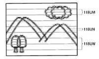
- the area dividing means 144 divides the parallax image display area 118 classified as shown in FIG. 19 by the display area classification means 142 into unit area sets 118U having different sizes for each partial display area 118D.
- the unit region set 118U has the shape of the above-described stripe lattice, the unit region set 118UW having the larger width, the unit region set 118UN having the smaller width, and the intermediate size of the unit region set 118UN. Is a unit area set 118UM.
- the image reflecting unit 146 displays the right eye image in the right eye unit region 118UR and the left eye image in the left eye unit region 118UL for each unit region set 118U (118UN, 118UM, 118UW).
- the image for the left eye and the image for the left eye are reflected.
- the parallax image generation unit 124 generates a parallax image based on the right-eye image and the left-eye image.
- the image acquisition unit 22 Upon receiving an instruction from the instruction input unit 16, the image acquisition unit 22 acquires a right-eye image and a left-eye image that can be stereoscopically viewed as shown in FIGS.
- the acquired right-eye image and left-eye image are output to the information amount distribution calculation unit 136, and the information amount distribution of the right-eye image and the information amount distribution of the left-eye image are calculated and output to the parallax image generation unit 124. Is done.
- the parallax image display area classification unit 142 of the parallax image generation unit 124 may display, for example, a parallax image display based on the information amount distribution of the right eye image and the information amount distribution of the left eye image calculated by the information amount distribution calculation unit 136.
- the areas are classified into three partial display areas 118D (N), (M), and (W) as shown in FIG.
- the area dividing means 144 divides the partial display area 118D classified as described above into unit area sets 118U having different sizes for each classification. For example, as shown in FIG. 19, the partial display area 118DN considered to have a large amount of information is divided into as small unit area sets 118UN as possible, and the partial display area 118DW considered to have a small amount of information has a unit area set as large as possible.
- the partial display area 118DM in the middle thereof is divided into unit area sets 118UM having an intermediate size.
- the image reflecting means 146 reflects the right-eye image in the right-eye unit region 118UR of the unit region set 118U (118UN, 118UM, 118UW), reflects the left-eye image in the left-eye unit region 118UL, and performs parallax. Generate an image.
- the subsequent operation is the same as in the first mode.
- the above is the operation of the parallax image display device 110 according to the second aspect of the present invention.
- parallax image generation method a parallax image generation method according to the second aspect of the present invention.
- the parallax image generation unit 124 generates a parallax image using the parallax image generation method of the present invention, and displays the parallax image on the second parallax image display unit 112.
- the parallax image generation unit 124 of the present invention includes an information amount distribution calculation unit 136 that calculates the information amount distribution of each of the right eye image and the left eye image.
- the information amount is, for example, (1) the amount of harmonic signal components of the image, (2) the value of the maximum frequency of the image, (3) the variance value of the luminance distribution of the image in the local region, (4 ) The amount of difference between the pixel values of the left and right original images.
- the information amount distribution of the right-eye image and the left-eye image is, for example, (1) the harmonics of the image among the information amounts described above.
- the amount of the wave signal component, that is, the fineness of the image is used as a reference.
- the right-eye image and the left-eye image are composed of, for example, (a) sky, (b) clouds, (c) mountains, (d) trees, and the like.
- the parallax image is an image in which the image for the right eye and the image for the left eye are displayed so as to overlap each other (displayed in a space-divided manner), and (a) to (d) of the edge portions.
- Information is important for performing highly accurate stereoscopic viewing.
- the parallax image display area 118 is displayed in the parallax image display area classification unit 142 by, for example, (N), (M), ( W) is divided into three partial display areas 118D (118DN, 118DM, 118DW).
- the parallax image generation unit 124 of the present invention divides the three different partial display areas 118D (N), (M), and (W) by the area dividing unit 144 by the unit area sets 118U having different sizes for each classification. To do. Note that the size of information in three different partial display areas 118D shown in FIG. 19 is in the order of (N)>(M)> (W), that is, the size of division of the partial display area 118D (that is, , Roughness) is in the order of (N) ⁇ (M) ⁇ (W).
- the unit region set 118U is a stripe lattice composed of a right-eye unit region 118UR and a left-eye unit region 118UL.
- M is intermediate and classification (W) is rough)
- W classification
- the stripe width of the unit region set 118U is, for example, a classification with a small amount of information (that is, a classification with a large stripe width) W for a stripe width of 16 pixels, an intermediate classification M with a stripe width of 8 pixels, and a classification with a large amount of information ( In other words, the stripe width of N) may be 4 pixels.
- the stripe width may be changed according to the pixel size of the parallax image, or may be changed according to the size or shape of the partial display region 118D.
- the area dividing means 144 of the present invention may change the dividing direction, that is, the stripe direction for each shape of the classified partial display area 118D. For example, when the partial display area 118D is long in the horizontal direction, the area dividing unit 144 may divide the partial display area 118D into vertical stripe lattices (unit area set 118U). This is to prevent interference (moire) between the dividing direction, that is, the stripe direction of the stripe grating and the spatial frequency of the image.
- the parallax image generation unit 124 In the parallax image display area 118, the parallax image generation unit 124 generates a parallax image by reflecting the right-eye image in the right-eye area 118R and the left-eye image in the left-eye area 118L, and the generated parallax image Are displayed on the second parallax image display unit 112 having the parallax image display area 118 (corresponding to the parallax image table area 118 on a one-to-one basis).
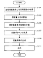
- the parallax image display device 110 acquires the right-eye image and the left-eye image taken for stereoscopic display through the parallax image generation unit 124 from an image server (not shown) or the like (step S101).
- the parallax image generation unit 124 calculates the information amount distribution in each of the right eye image and the left eye image (step S103). As described above, for example, (1) the amount of harmonic signal components of the image, (2) the value of the maximum frequency of the image, (3) the variance value of the luminance distribution of the image within the local region, (4) the left and right The information amount distribution is calculated using at least one of the difference amounts of the pixel values of the original image as the information amount.
- the parallax image generation unit 124 classifies the parallax image display region 118 into a plurality of partial display regions 118D from the information amount distribution of the right-eye image and the information amount distribution of the left-eye image.
- the parallax image display region 118 is classified by the parallax image display region classification unit of the parallax image generation unit 124, for example, from the difference amount between the information amount distribution of the right-eye image and the information amount distribution of the left-eye image, This is performed based on image edge information and the like (step S105).
- the parallax image display area 118 is classified into, for example, three partial display areas 118D (N), (M), and (W) as shown in FIG. There are three parts: an edge peripheral part (N), a cloud and tree part (M) with a large amount of information in the original image, and a sky and mountain part (W) with a small amount of information.
- the parallax image generation unit 124 divides the partial display region 118D into unit region sets 118U (right-eye unit region 118UR and left-eye unit region 118UL) having different sizes according to the classification by the region dividing unit. (Step S107). For example, assuming that the right-eye unit region 118UR and the left-eye unit region 118UL are stripe lattices, the stripe widths in the classifications (N), (M), and (W) of the partial display region 118D are small, medium, Divide from large.
- the parallax image display area 118 is displayed as shown in FIG. 21 by the right-eye unit area 118UR and the left-eye unit area 118UL which are stripe lattices. Further, the direction of the stripe lattice may be changed to a direction in which moiré is unlikely to occur, such as vertical, horizontal, or diagonal, according to the shape of the partial display region 118D (118DN, 118DM, 118DW).
- the parallax image generation unit 124 the parallax image is generated by reflecting the left-eye image and the right-eye image on all the right-eye regions 118R and the left-eye regions 118L on the parallax image display region 118 (step S109).
- the displayed space-divided parallax image is a parallax image that hardly causes crosstalk and does not impair the transmission of image information.
- the generated parallax image is displayed on the second parallax image display unit 112 in which the display screen has a one-to-one correspondence with the parallax image display region 118 (step S111).
- these parallax images may be displayed not only on the second parallax image display unit 112 but also by an output device such as a printer. This is because the present invention is a space-divided stereoscopic display and does not require electrical driving.
- parallax image print> As described above, the parallax image generated by the parallax image generation method is not only displayed on the second parallax image display unit 112 of the parallax image display device 110 described above, but also a printer (not shown), as in the first mode.
- the parallax image can be printed by printing on a sheet of paper.
- a polarizing film corresponding to the left-eye region 118L and the right-eye region 118R of the parallax image is further pasted on the parallax image.
- the left eye image is recognized by the observer's left eye
- the right eye image is recognized by the observer's right eye, so that the observer can perform stereoscopic display.
- the second parallax image display unit 112 may include a parallax barrier 50 described later instead of the polarizing filter 48.
- the parallax image is limited to the parallax image divided in a stripe lattice shape in the vertical direction shown in FIG. 9B (direction perpendicular to the direction in which the eyes of the observer are lined up).
- a parallax barrier control unit 31 that controls the parallax barrier in accordance with the parallax image (parallax image display region 118) generated by the parallax image generation unit 124 is provided.
- the polarizing glasses 14 are not necessary, and stereoscopic vision can be performed with the naked eye.
- the parallax barrier 50 is configured by a switch liquid crystal or the like that can electrically switch the presence / absence of light transmission in an arbitrary region in units of pixels. Further, the parallax barrier control unit 31 controls the parallax barrier 50 by electrically controlling the switch liquid crystal.
- the parallax barrier 50 is arranged at a predetermined interval distance in front of the second parallax image display unit 112, so that the right-eye image is observed by the right eye and the left eye is observed by the left eye, as shown in FIG. Since the work image is observed, the observer can perform a stereoscopic view using the right eye image and the left eye image.
- the display area (information amount) of the right-eye image and the display area of the left-eye image are substantially the same.
- the parallax image display device 110 includes the above-described parallax barrier 50 on the front surface of the second parallax image display unit 112, and is vertically striped by the parallax image generation unit 124.
- the parallax barrier 50 is operated so that the left-eye image of the parallax image is observed.
- the parallax image is limited to the vertical stripe grid as described above, and therefore the partial display region 118D classified as shown in FIG. Instead of the horizontal stripe lattice shown in FIG. 20, the image is divided into the vertical stripe lattice shown in FIG. 23 to generate a parallax image.
- the observer recognizes the image for the right eye with the right eye and the image for the left eye with the left eye. It is possible to perform autostereoscopic viewing based on the right-eye image.
- a parallax barrier film can be used instead of the polarizing film.
- the polarizing glasses 14 are not necessary, and stereoscopic vision can be performed with the naked eye, as described above.
- the parallax barrier film for example, a combination of a light-impermeable film that does not transmit light and a light-transmitting film that transmits light can be considered.
- a parallax barrier film configured according to the parallax image is placed (pasted) at a predetermined interval on the front surface of the parallax image print to observe an observer away from the parallax image print by a predetermined interval. Since the right eye image is observed by the right eye of the viewer and the left eye image is observed by the left eye of the viewer, the viewer can perform autostereoscopic viewing based on the right eye image and the left eye image.
- the parallax image display device As described above, the parallax image display device, the parallax image generation method, and the parallax image print of the present invention have been described in detail. However, the present invention is not limited to the above-described embodiments and does not depart from the gist of the present invention. In the above, various improvements and changes may be made.
- Parallax image display device First parallax image display unit (parallax image display means) 112 2nd parallax image display part (parallax image display means) 14 Polarized Glasses 16 Operation Input Unit 18, 118 Parallax Image Display Area 18R, 118R Right Eye Area (Right Eye Image Display Area) 18L, 118L Left eye area (left eye image display area) 118D Partial display area 18U Reference area 118U Unit area set 18UR, 118UR Right eye unit area 18UL, 118UL Left eye unit area 20, 120 Console 22 Image acquisition unit 24, 124 Parallax image generation unit 26 Control unit 28 Display control unit 30 Polarization filter Control unit 31, 131 Parallax barrier control unit 34 Storage unit 36, 136 Information amount distribution calculation unit 37 Information amount comparison unit 38 Reference region allocation unit 40 Luminance value adjustment unit 142 Parallax image display region classification unit 144 Region division unit 46, 146 Image Reflecting means 48 Polarizing filter 49 Two-layer parallax barrier 50 Parallax barrier
Landscapes
- Physics & Mathematics (AREA)
- General Physics & Mathematics (AREA)
- Engineering & Computer Science (AREA)
- Multimedia (AREA)
- Signal Processing (AREA)
- Optics & Photonics (AREA)
- Testing, Inspecting, Measuring Of Stereoscopic Televisions And Televisions (AREA)
Abstract
Priority Applications (4)
| Application Number | Priority Date | Filing Date | Title |
|---|---|---|---|
| EP12786395.9A EP2712197B1 (fr) | 2011-05-16 | 2012-05-16 | Dispositif d'affichage d'images avec parallaxe, procédé de génération d'images avec parallaxe et impression d'images avec parallaxe |
| KR1020137030279A KR101592304B1 (ko) | 2011-05-16 | 2012-05-16 | 시차 화상 표시 장치, 시차 화상 생성 방법, 및 시차 화상 프린트 |
| CN201280023213.5A CN103535030B (zh) | 2011-05-16 | 2012-05-16 | 视差图像显示装置、视差图像生成方法、视差图像打印 |
| US14/081,333 US10171799B2 (en) | 2011-05-16 | 2013-11-15 | Parallax image display device, parallax image generation method, parallax image print |
Applications Claiming Priority (4)
| Application Number | Priority Date | Filing Date | Title |
|---|---|---|---|
| JP2011-109452 | 2011-05-16 | ||
| JP2011109217A JP5753439B2 (ja) | 2011-05-16 | 2011-05-16 | 視差画像表示装置、視差画像生成方法、及び視差画像プリント |
| JP2011109452 | 2011-05-16 | ||
| JP2011-109217 | 2011-05-16 |
Related Child Applications (1)
| Application Number | Title | Priority Date | Filing Date |
|---|---|---|---|
| US14/081,333 Continuation US10171799B2 (en) | 2011-05-16 | 2013-11-15 | Parallax image display device, parallax image generation method, parallax image print |
Publications (1)
| Publication Number | Publication Date |
|---|---|
| WO2012157666A1 true WO2012157666A1 (fr) | 2012-11-22 |
Family
ID=47176983
Family Applications (1)
| Application Number | Title | Priority Date | Filing Date |
|---|---|---|---|
| PCT/JP2012/062489 Ceased WO2012157666A1 (fr) | 2011-05-16 | 2012-05-16 | Dispositif d'affichage d'images avec parallaxe, procédé de génération d'images avec parallaxe et impression d'images avec parallaxe |
Country Status (5)
| Country | Link |
|---|---|
| US (1) | US10171799B2 (fr) |
| EP (1) | EP2712197B1 (fr) |
| KR (1) | KR101592304B1 (fr) |
| CN (1) | CN103535030B (fr) |
| WO (1) | WO2012157666A1 (fr) |
Cited By (1)
| Publication number | Priority date | Publication date | Assignee | Title |
|---|---|---|---|---|
| JPWO2012172888A1 (ja) * | 2011-06-16 | 2015-02-23 | シャープ株式会社 | 画像生成装置、画像生成方法、画像生成プログラム、及び記録媒体 |
Families Citing this family (6)
| Publication number | Priority date | Publication date | Assignee | Title |
|---|---|---|---|---|
| KR102706279B1 (ko) * | 2016-10-18 | 2024-09-19 | 삼성디스플레이 주식회사 | 표시 패널, 이를 포함하는 머리 부착형 표시 장치, 및 머리 부착형 표시 장치의 영상 표시 방법 |
| CN108196376A (zh) * | 2018-01-22 | 2018-06-22 | 成都工业学院 | 一种3d显示器 |
| CN112136073A (zh) | 2018-03-14 | 2020-12-25 | 奇跃公司 | 用于剪辑内容以增加观看舒适感的显示系统和方法 |
| US11619829B2 (en) * | 2020-12-10 | 2023-04-04 | Lumileds Llc | Line pattern projections for three dimension display |
| KR102838997B1 (ko) | 2021-05-06 | 2025-07-29 | 삼성디스플레이 주식회사 | 표시 장치 및 이의 구동 방법 |
| TWI812566B (zh) * | 2022-12-28 | 2023-08-11 | 宏碁股份有限公司 | 立體影像深度調整方法與裝置 |
Citations (6)
| Publication number | Priority date | Publication date | Assignee | Title |
|---|---|---|---|---|
| JPH06194602A (ja) * | 1992-12-24 | 1994-07-15 | Nippon Telegr & Teleph Corp <Ntt> | 両眼立体視装置 |
| JPH07307959A (ja) | 1994-05-12 | 1995-11-21 | Nippon Hoso Kyokai <Nhk> | 立体映像装置 |
| JPH09265056A (ja) | 1995-07-14 | 1997-10-07 | Pioneer Electron Corp | 立体画像表示装置 |
| JPH10221643A (ja) | 1997-01-31 | 1998-08-21 | Canon Inc | 立体画像表示装置 |
| JP2005215326A (ja) | 2004-01-29 | 2005-08-11 | Arisawa Mfg Co Ltd | 偏光透過スクリーン、及び当該偏光透過スクリーンを用いた立体画像表示装置 |
| JP2009193014A (ja) | 2008-02-18 | 2009-08-27 | Fujifilm Corp | パターニング楕円偏光板 |
Family Cites Families (11)
| Publication number | Priority date | Publication date | Assignee | Title |
|---|---|---|---|---|
| GB2309609A (en) * | 1996-01-26 | 1997-07-30 | Sharp Kk | Observer tracking autostereoscopic directional display |
| JP3235776B2 (ja) | 1996-08-07 | 2001-12-04 | 三洋電機株式会社 | 立体感調整方法および立体感調整装置 |
| EP0918439B1 (fr) * | 1996-07-18 | 2008-12-24 | SANYO ELECTRIC Co., Ltd. | Dispositif pour convertir des signaux video bidimensionnels en signaux video tridimensionnels |
| JP2005353047A (ja) * | 2004-05-13 | 2005-12-22 | Sanyo Electric Co Ltd | 立体画像処理方法および立体画像処理装置 |
| JP4652727B2 (ja) * | 2004-06-14 | 2011-03-16 | キヤノン株式会社 | 立体画像生成システムおよびその制御方法 |
| JP2007065067A (ja) * | 2005-08-29 | 2007-03-15 | Seijiro Tomita | 立体映像表示装置 |
| JP4476905B2 (ja) * | 2005-08-31 | 2010-06-09 | 株式会社東芝 | 立体表示画像データの構造、立体表示画像データの記録方法、表示再生方法、記録プログラム、および表示再生プログラム |
| US8487982B2 (en) | 2007-06-07 | 2013-07-16 | Reald Inc. | Stereoplexing for film and video applications |
| US8749615B2 (en) * | 2007-06-07 | 2014-06-10 | Reald Inc. | Demultiplexing for stereoplexed film and video applications |
| JP5127633B2 (ja) * | 2008-08-25 | 2013-01-23 | 三菱電機株式会社 | コンテンツ再生装置および方法 |
| US8854531B2 (en) * | 2009-12-31 | 2014-10-07 | Broadcom Corporation | Multiple remote controllers that each simultaneously controls a different visual presentation of a 2D/3D display |
-
2012
- 2012-05-16 EP EP12786395.9A patent/EP2712197B1/fr not_active Not-in-force
- 2012-05-16 CN CN201280023213.5A patent/CN103535030B/zh active Active
- 2012-05-16 KR KR1020137030279A patent/KR101592304B1/ko not_active Expired - Fee Related
- 2012-05-16 WO PCT/JP2012/062489 patent/WO2012157666A1/fr not_active Ceased
-
2013
- 2013-11-15 US US14/081,333 patent/US10171799B2/en active Active
Patent Citations (6)
| Publication number | Priority date | Publication date | Assignee | Title |
|---|---|---|---|---|
| JPH06194602A (ja) * | 1992-12-24 | 1994-07-15 | Nippon Telegr & Teleph Corp <Ntt> | 両眼立体視装置 |
| JPH07307959A (ja) | 1994-05-12 | 1995-11-21 | Nippon Hoso Kyokai <Nhk> | 立体映像装置 |
| JPH09265056A (ja) | 1995-07-14 | 1997-10-07 | Pioneer Electron Corp | 立体画像表示装置 |
| JPH10221643A (ja) | 1997-01-31 | 1998-08-21 | Canon Inc | 立体画像表示装置 |
| JP2005215326A (ja) | 2004-01-29 | 2005-08-11 | Arisawa Mfg Co Ltd | 偏光透過スクリーン、及び当該偏光透過スクリーンを用いた立体画像表示装置 |
| JP2009193014A (ja) | 2008-02-18 | 2009-08-27 | Fujifilm Corp | パターニング楕円偏光板 |
Non-Patent Citations (1)
| Title |
|---|
| See also references of EP2712197A4 |
Cited By (1)
| Publication number | Priority date | Publication date | Assignee | Title |
|---|---|---|---|---|
| JPWO2012172888A1 (ja) * | 2011-06-16 | 2015-02-23 | シャープ株式会社 | 画像生成装置、画像生成方法、画像生成プログラム、及び記録媒体 |
Also Published As
| Publication number | Publication date |
|---|---|
| EP2712197B1 (fr) | 2017-11-08 |
| CN103535030A (zh) | 2014-01-22 |
| KR101592304B1 (ko) | 2016-02-05 |
| EP2712197A1 (fr) | 2014-03-26 |
| KR20140022899A (ko) | 2014-02-25 |
| US20140085442A1 (en) | 2014-03-27 |
| CN103535030B (zh) | 2016-04-13 |
| US10171799B2 (en) | 2019-01-01 |
| EP2712197A4 (fr) | 2015-04-01 |
Similar Documents
| Publication | Publication Date | Title |
|---|---|---|
| US10171799B2 (en) | Parallax image display device, parallax image generation method, parallax image print | |
| JP5643160B2 (ja) | 表示装置 | |
| JP3979604B2 (ja) | ディスプレイ | |
| US20100046069A1 (en) | Method and arrangement for three-dimensional representation | |
| KR20120109303A (ko) | 표시 장치 | |
| EP1708010A1 (fr) | Appareil d'affichage d'image | |
| JP2016140056A (ja) | 立体表示装置及び視差画像補正方法 | |
| WO2013061734A1 (fr) | Dispositif d'affichage 3d | |
| TW200900736A (en) | Hybrid multiplexed 3D display and a displaying method thereof | |
| CN107113419A (zh) | 自动立体多视图系统 | |
| CA2917088A1 (fr) | Dispositif d'affichage auto-stereoscopique ayant un retroeclairage a bandes et deux reseaux de lentilles lenticulaires | |
| Kakeya et al. | Time-division quadruplexing parallax barrier with subpixel-based slit control | |
| JP2012073618A (ja) | 自動立体ディスプレー装置 | |
| US10499032B2 (en) | Naked-eye stereoscopic display and method of displaying a stereoscopic image | |
| US12313936B1 (en) | Multiscopic display using multiscopic optical element with multiple liquid crystal layers | |
| JP5603370B2 (ja) | 視差画像表示装置、視差画像生成方法、及び視差画像プリント | |
| US20080158671A1 (en) | Three-Dimensional Image Display Apparatus Using Flat Panel Display | |
| JP5753439B2 (ja) | 視差画像表示装置、視差画像生成方法、及び視差画像プリント | |
| JP2011033819A (ja) | 3次元画像表示装置 | |
| JP5749974B2 (ja) | 視差画像表示装置、視差画像生成方法、及び視差画像プリント | |
| JP2008015121A (ja) | 多視点立体ディスプレイ装置 | |
| KR101957148B1 (ko) | 3차원 영상 표시장치 | |
| US9110297B2 (en) | Image display device | |
| KR20140093323A (ko) | 3차원 영상 표시장치 | |
| KR20110136323A (ko) | 패럴랙스 배리어 패널 및 그의 구동 방법 |
Legal Events
| Date | Code | Title | Description |
|---|---|---|---|
| 121 | Ep: the epo has been informed by wipo that ep was designated in this application |
Ref document number: 12786395 Country of ref document: EP Kind code of ref document: A1 |
|
| REEP | Request for entry into the european phase |
Ref document number: 2012786395 Country of ref document: EP |
|
| WWE | Wipo information: entry into national phase |
Ref document number: 2012786395 Country of ref document: EP |
|
| ENP | Entry into the national phase |
Ref document number: 20137030279 Country of ref document: KR Kind code of ref document: A |
|
| NENP | Non-entry into the national phase |
Ref country code: DE |