WO2012157668A1 - Appareil de filtration et procédé de nettoyage d'un appareil de filtration - Google Patents
Appareil de filtration et procédé de nettoyage d'un appareil de filtration Download PDFInfo
- Publication number
- WO2012157668A1 WO2012157668A1 PCT/JP2012/062500 JP2012062500W WO2012157668A1 WO 2012157668 A1 WO2012157668 A1 WO 2012157668A1 JP 2012062500 W JP2012062500 W JP 2012062500W WO 2012157668 A1 WO2012157668 A1 WO 2012157668A1
- Authority
- WO
- WIPO (PCT)
- Prior art keywords
- ozone
- liquid
- gas
- filtration
- pipe
- Prior art date
- Legal status (The legal status is an assumption and is not a legal conclusion. Google has not performed a legal analysis and makes no representation as to the accuracy of the status listed.)
- Ceased
Links
Images



Classifications
-
- C—CHEMISTRY; METALLURGY
- C02—TREATMENT OF WATER, WASTE WATER, SEWAGE, OR SLUDGE
- C02F—TREATMENT OF WATER, WASTE WATER, SEWAGE, OR SLUDGE
- C02F1/00—Treatment of water, waste water, or sewage
- C02F1/44—Treatment of water, waste water, or sewage by dialysis, osmosis or reverse osmosis
-
- B—PERFORMING OPERATIONS; TRANSPORTING
- B01—PHYSICAL OR CHEMICAL PROCESSES OR APPARATUS IN GENERAL
- B01D—SEPARATION
- B01D65/00—Accessories or auxiliary operations, in general, for separation processes or apparatus using semi-permeable membranes
- B01D65/02—Membrane cleaning or sterilisation ; Membrane regeneration
-
- B—PERFORMING OPERATIONS; TRANSPORTING
- B01—PHYSICAL OR CHEMICAL PROCESSES OR APPARATUS IN GENERAL
- B01D—SEPARATION
- B01D2321/00—Details relating to membrane cleaning, regeneration, sterilization or to the prevention of fouling
- B01D2321/16—Use of chemical agents
- B01D2321/168—Use of other chemical agents
-
- C—CHEMISTRY; METALLURGY
- C02—TREATMENT OF WATER, WASTE WATER, SEWAGE, OR SLUDGE
- C02F—TREATMENT OF WATER, WASTE WATER, SEWAGE, OR SLUDGE
- C02F1/00—Treatment of water, waste water, or sewage
- C02F1/72—Treatment of water, waste water, or sewage by oxidation
- C02F1/78—Treatment of water, waste water, or sewage by oxidation with ozone
-
- C—CHEMISTRY; METALLURGY
- C02—TREATMENT OF WATER, WASTE WATER, SEWAGE, OR SLUDGE
- C02F—TREATMENT OF WATER, WASTE WATER, SEWAGE, OR SLUDGE
- C02F2303/00—Specific treatment goals
- C02F2303/16—Regeneration of sorbents, filters
Definitions
- the present invention relates to a filtration apparatus equipped with a filtration membrane and a cleaning method for the filtration treatment apparatus, and in particular, a water purifier equipped with a filtration membrane and capable of washing the filtration membrane using an ozone-containing liquid, and the The present invention relates to a cleaning method using an ozone-containing liquid in a water purifier.
- Patent Document 1 discloses a water treatment apparatus including an ozone water generator, a filtration membrane, a washing water supply line, and a bypass line. In the processing apparatus, a technique for cleaning a filtration membrane with ozone water generated by an ozone water generator is disclosed.
- the water treatment device disclosed in the above publication does not perform any special treatment on the ozone water used for cleaning, and drains the ozone water directly to the outside of the water treatment device. For this reason, there is a risk that high-concentration ozone gas contained in ozone water may be released to the atmosphere. It is generally known that when the ozone gas has a low concentration, the human body is not affected, but when the ozone gas having a high concentration is directly inhaled, the human body is adversely affected. For this reason, it can be said that the water treatment apparatus disclosed in the above publication is in a difficult situation in terms of safety.
- the present invention has been made in view of the above-described problems, and can be safely released to the atmosphere or reused ozone gas by gas-liquid separation of the ozone-containing liquid used for cleaning. It aims at providing the washing
- the filtration apparatus includes a filtration unit that performs filtration treatment of a liquid, and is configured to be able to wash the filtration unit using an ozone-containing liquid, and includes an ozone-containing liquid that generates an ozone-containing liquid.
- the first gas-liquid separator is provided.
- the filtration apparatus may further include a path for supplying the liquid filtered by the filtration unit to the first gas-liquid separator.
- the ozone-containing liquid generator may have an ozone-containing liquid generation unit and a liquid supply source.
- the liquid supply source is filtered. It is preferable to be connected to a liquid supply path for supplying the liquid filtered by the unit to the liquid supply source.
- the first gas-liquid separator may have a gas outlet, and in that case, an ozone filter may be provided at the gas outlet. preferable.
- the ozone-containing liquid generation unit may include an ozone generator that generates ozone gas and a gas-liquid mixer that mixes ozone gas and liquid.
- the ozone-containing liquid generator is connected to an ozone generator that generates ozone gas, a gas-liquid mixer that mixes ozone gas and liquid, and a gas-liquid mixer.
- a second gas-liquid separator may be included, and in that case, it is preferable that the filtration apparatus includes a circulation path for circulating gas in the ozone generator.
- the first gas-liquid separator is preferably connected to the ozone-containing liquid generator.
- the method for cleaning a filtration apparatus is a method for cleaning a filtration part of a filtration apparatus using an ozone-containing liquid, and the filtration part is washed with an ozone-containing liquid generated by an ozone-containing liquid generator.
- the ozone-containing liquid after being used for cleaning the filtration part is introduced into the first gas-liquid separator and separated into the ozone-containing liquid and the ozone gas, and after the separation in the first gas-liquid separator A step of decomposing the ozone gas with an ozone filter.
- the ozone-containing liquid used for cleaning is gas-liquid separated so that it can be safely opened to the atmosphere or the ozone gas can be reused, thereby preventing the release of high-concentration ozone gas into the atmosphere. It can be set as the washing
- Embodiment 1 It is the schematic of the filtration processing apparatus which concerns on Embodiment 1 of this invention. It is the schematic which shows one structural example of the filtration part shown in FIG. It is the schematic which shows one structural example of the ozone containing liquid production
- FIG. 1 is a schematic view of a filtration apparatus according to Embodiment 1 of the present invention.
- the filtration processing apparatus 100 in FIG. 1 includes a filtration unit 101, an ozone-containing liquid generator 102 that generates an ozone-containing liquid used for cleaning, and a first unit that separates the ozone-containing liquid after being used for cleaning into a gas and a liquid.
- gas-liquid separator 103 gas-liquid separator 103, a liquid supply source 108 in which a liquid such as water to be treated is stored, and a pumping unit 110 that pumps the liquid, and the filter unit 101 is washed with an ozone-containing liquid.
- the filtration unit 101 is configured by a filtration membrane.
- a filtration membrane By passing a mixture in which a solid substance is mixed in a liquid or gas from one direction through a filtration membrane having fine holes, solid particles larger than the hole can be passed through the liquid or gas.
- a general filtration membrane such as a hollow fiber filter, an activated carbon filter, or an ion exchange resin filter can be used.
- the filtration unit 101 is connected to the pipe a and the pipe b, filters the liquid such as water introduced from the pipe a during the filtration process, and guides the filtered liquid to the pipe b.
- the ozone-containing liquid is introduced into the filtration unit 101 from the pipe b in the direction opposite to the flow direction at the time of the filtration process, and the ozone-containing liquid after being used for the cleaning is filtered.
- the backwashing of the filtration part 101 using an ozone containing liquid is performed.
- reverse cleaning is a cleaning method for cleaning a filtration membrane by flowing a liquid in a direction opposite to the filtration direction, and solids and organic substances such as inorganic substances attached to the filtration membrane that cannot be removed in the filtration direction.
- This is a cleaning method that eliminates clogging of filtration membranes caused by contaminants such as
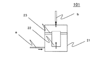
- FIG. 2 is a schematic diagram illustrating a configuration example of the filtration unit illustrated in FIG. 1.
- the filtration treatment tank 21 for storing a solution to be treated, a filtration membrane 22, and a partition plate 23.
- the filtration treatment tank 21 is divided into two spaces by the filtration membrane 22 and the partition plate 23. It has the structure divided into. For this reason, the to-be-processed solution introduced from the pipe a is stored in the filtration tank 21 and passes through the filtration membrane 22 when the water level exceeds a certain level, and the filtration process is performed at that time.
- the solution to be treated that has been subjected to the filtration treatment is led out from the pipe b.
- a hollow fiber filter is used as the filtration membrane 22, and in this case, the solution to be treated that is in contact with the surface of the hollow fiber filter is sucked up by a capillary phenomenon or a pressure difference between the inside and outside of the hollow fiber, and the hollow fiber filter is used. Is filtered.
- the ozone-containing liquid generator 102 in FIG. 1 includes an ozone-containing liquid generation unit 112, a liquid supply source 109 that stores the liquid supplied to the ozone-containing liquid generation unit 112, and a pressure-feeding capable of pumping the liquid.
- the liquid stored in the liquid supply source 109 by the pressure feeding unit 111 is supplied to the ozone-containing liquid generation unit 112, and thereby the ozone-containing liquid generation unit 112 generates an ozone-containing liquid.
- the ozone-containing liquid generation unit 112 is connected to a pipe d connected in communication with the pipe b and a pipe g connected in communication with the liquid supply source 109, and has a liquid supplied from the liquid supply source 109. And an ozone-containing liquid is generated, and the generated ozone-containing liquid is supplied to the pipe b through the pipe d.
- the pipe d is provided with an on-off valve V2, which makes it possible to control the supply amount of the ozone-containing liquid.
- the pipe g is connected to a pumping unit 111 formed from a pump or the like, and the pumping unit 111 pumps the liquid of the liquid supply source 109 to the ozone-containing liquid generation unit 112 via the pipe g.
- the ozone-containing liquid generator 102 may be configured such that a water pipe or the like provided with an on-off valve is directly connected to the ozone-containing liquid generating unit 112.
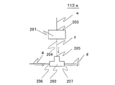
- FIG. 3 is a schematic diagram illustrating a configuration example of the ozone-containing liquid generation unit illustrated in FIG. 1.
- the ozone-containing liquid generation unit 112a in FIG. 3 generates ozone-containing liquid as a gas-liquid mixture by mixing the ozone gas generated by the ozone generator 201 and a liquid such as water in the gas-liquid mixer 202. It is.
- the gas-liquid mixture means a liquid in which a gas is dissolved in a liquid or a liquid in which a gas is contained as bubbles in a liquid, and an ozone solution or a liquid in which ozone gas is dissolved in a liquid.
- An ozone bubble liquid in which ozone gas is mixed as bubbles is included.
- the liquid to be mixed includes a solution in which ozone gas is mixed, such as water or a cultivation nutrient solution used as an agricultural solvent or a solution used as a medical solvent.
- a gas such as air or oxygen is introduced from the gas inlet 203 through the pipe e.
- the ozone generator 201 generates ozone gas by an ozone generation element provided in the ozone generator 201 and guides the generated ozone gas from the gas outlet port 204 to the pipe f.
- one end of the pipe e is connected to the gas inlet 203 of the ozone generator 201, and the other end is connected to the atmosphere or a cylinder storing oxygen or air (not shown).
- ozone gas is introduced from the gas inlet 205 via the pipe f, and liquid such as water is pumped and introduced from the liquid inlet 206 via the pipe g.
- an ozone-containing liquid is generated by mixing the introduced ozone gas and a liquid such as water, and the generated ozone-containing liquid is supplied from the outlet 207 to the pipe d.
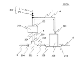
- FIG. 4 is a schematic diagram illustrating another configuration example of the ozone-containing liquid generation unit illustrated in FIG. 1.
- the ozone-containing liquid generator 112b according to the other configuration example is a gas circulation type ozone-containing liquid generator.
- symbol is attached
- the circulation path A is a path provided in the ozone-containing liquid generation unit 112b through which gas or liquid circulates, and is formed by the pipe i, the pipe f, and the pipe h.
- the gas in the ozone-containing liquid generation unit 112b is introduced into the ozone generator 201 via the circulation path A, and thereby ozone gas is generated in the ozone generator 201.
- the generated ozone gas is introduced into the gas-liquid mixer 202 from the gas inlet 205 of the gas-liquid mixer 202 through the pipe f, and is a liquid such as water introduced from the liquid inlet 206 through the pipe g.
- an ozone-containing liquid is generated in the gas-liquid mixer 202.
- the generated ozone-containing liquid is led out from the outlet 207 to the pipe h.
- the ozone-containing liquid led out to the pipe h is introduced into the second gas-liquid separator 208 from the introduction port 209 of the second gas-liquid separator 208, and the second gas-liquid separator 208 uses the liquid and gas. Separated.
- the liquid after being separated in the second gas-liquid separator 208 is led out from the liquid outlet 210, and the gas after being separated in the second gas-liquid separator 208 is led out from the gas outlet 211. .
- the ozone-containing liquid includes an ozone solution in which ozone gas is dissolved in the liquid and an ozone bubble liquid in which the ozone gas is mixed as bubbles in the liquid.
- the second gas-liquid separator 208 means that the gas is separated into a gas containing ozone gas or air and a liquid containing an ozone solution.
- the liquid ozone solution is led out from the liquid outlet 210 to the pipe d.
- a gas containing ozone gas or oxygen is led out from the gas outlet 211 and is again introduced into the ozone generator 201 through the pipe i.
- the ozone generator 201 will generate ozone gas based on the gas containing the circulating ozone gas, and can generate higher concentration ozone gas, resulting in the generation of high concentration ozone-containing liquid. It becomes possible.
- the gas introduction part 212 which introduces gas from the outside of the ozone containing liquid production
- the gas circulation type ozone-containing liquid generation unit 112b generates ozone gas using the gas confined in the ozone-containing liquid generation unit 112b as a material and dissolves the gas in the liquid, and then discharges the gas to the outside.
- the gas in the ozone-containing liquid generating part 112b is insufficient when the operation of the ozone-containing liquid generating part 112b is continued for a long time. Become. For this reason, in order to introduce the insufficient gas into the ozone-containing liquid generation unit 112b, it is preferable to provide the gas introduction unit 212 described above.
- the gas introduction part 212 has a configuration in which an opening / closing valve V5 is provided in the pipe j.
- One of the pipes j is connected to the pipe i that is partially opened, and the other is connected to the atmosphere or oxygen. Connected to a cylinder that stores air.
- the gas introduction part 212 is good also as a structure by which the on-off valve V5 was provided directly without connecting the pipe i to the open pipe i, and introduce
- a liquid supply source 108 plays a role as a liquid storage tank in which a liquid such as water as a solution to be processed is stored, and is provided with a pumping unit 110 formed from a pump or the like. Connected to the pipe a. Thereby, a liquid such as water is supplied from the liquid supply source 108 to the pipe a.
- the filtration apparatus 100 may have a configuration in which a water pipe having a pipe a and an on-off valve is directly connected to the filtration unit 101.
- the first gas-liquid separator 103 shown in FIG. 1 a general gas-liquid separator having a function of separating the introduced gas-liquid mixture into gas and liquid can be used.
- the first gas-liquid separator 103 is formed in the shape of a cylindrical liquid storage tank that stores liquid, or in a structure in which a gas-liquid separator is formed in a pipe.
- the first gas-liquid separator 103 is provided so as to be connected to a pipe c communicating with the pipe a, whereby the first gas-liquid separator 103 has an ozone-containing liquid after being used for cleaning. Is introduced.
- the ozone-containing liquid introduced into the first gas-liquid separator 103 is separated into liquid and gas in the first gas-liquid separator 103, and the gas containing ozone gas is passed through the gas outlet 105 from the filtration processing apparatus 100.
- the ozone filter 106 may be disposed in a path that leads from the gas outlet 105 to the outside of the filtration apparatus 100, so that a gas containing ozone gas may be derived through the ozone filter 106.
- the ozone filter 106 is composed of paper or aluminum having an ozone decomposing catalyst attached in a lattice shape, and decomposes ozone gas passing through the ozone filter 106. Therefore, by providing the ozone filter 106, the gas can be safely discharged from the gas outlet 105.
- the ozone solution after the gas-liquid separation is stored in the first gas-liquid separator 103 or led out of the filtration apparatus 100 from the liquid outlet 107.
- the pipe c is provided with an on-off valve V4, whereby the flow rate of the liquid introduced into the first gas-liquid separator 103 can be controlled.
- the pipe d is provided with an on-off valve V2, whereby the supply amount of the ozone-containing liquid supplied to the filtration unit 101 can be controlled.
- the pipe a is provided with an on-off valve V1 between the liquid supply source 108 and a connection portion C1 that is a portion to which the pipe c is connected, thereby introducing the solution to be treated introduced into the filtration apparatus 100. It is possible to control the amount.
- the pipe b is provided with an on-off valve V3 between the connection portion C2 that is a portion to which the pipe d is connected and the external port 104, thereby controlling the amount of liquid discharged from the external port 104. It is possible. Therefore, by using the on-off valves V1 to V4, it is possible to switch between filtration processing and cleaning.
- the filtration device 100 has a function of filtering the solution to be treated by the filtration unit 101 and a function of cleaning the filtration unit 101.
- the filtration process is an operation of filtering the solution to be treated by the filtration unit 101.
- the on-off valve V1 is opened, the on-off valve V2 is closed, the on-off valve V3 is opened, the on-off valve V4 is closed, and a solution to be treated such as water from the liquid supply source 108. Is supplied to the filtration unit 101.
- a solution to be treated such as water is supplied from the liquid supply source 108 to the filtration unit 101 via the pipe a. After the filtration process is performed in the filtration unit 101, the solution to be treated after the filtration process is supplied from the filtration unit 101. It is led out to the pipe b. Thereafter, the solution to be treated after the filtration process is led out of the filtration apparatus 100 through the external port 104 provided in the pipe b.
- the piping b forms a filtration path through which the solution to be treated after the filtration treatment flows.
- the filtration path means a path for leading the solution to be processed after the filtration process by the filtration unit 101 to the outside of the filtration apparatus 100.
- the cleaning treatment is an operation of generating an ozone-containing liquid in the ozone-containing liquid generator 102 and cleaning the filter unit 101 or the piping using the generated ozone-containing liquid.
- the on-off valve V1 is closed, the on-off valve V2 is opened, the on-off valve V3 is closed, the on-off valve V4 is opened, and the ozone-containing liquid generation unit 112 filters the ozone-containing liquid. Introduced into 101, the cleaning is performed.
- the ozone-containing liquid generated by the ozone-containing liquid generating unit 112 is introduced into the pipe b through the pipe d. Thereafter, the ozone-containing liquid is introduced into the filtration unit 101 via the pipe b, and the filtration unit 101 is washed.
- the ozone-containing liquid after being used for cleaning follows the pipe a and the pipe c as a waste ozone-containing liquid, and is introduced into the first gas-liquid separator 103. Thereafter, the waste ozone-containing liquid is separated into gas and liquid in the first gas-liquid separator 103, and the gas containing ozone gas is led out from the gas outlet 105. At this time, the ozone gas led out from the gas lead-out port 105 is led out after being decomposed by the ozone filter 106. On the other hand, the waste ozone-containing liquid is led out from the liquid outlet 107.
- a cleaning path through which the ozone-containing liquid that is the cleaning liquid flows is formed by a path that leads from the connection portion C2 between the piping d and the piping b to the filtration portion 101.
- a drainage path through which the waste ozone-containing liquid used for cleaning is drained is formed by the path leading from the filtration part 101 of the pipe a to the connection part C1 and the pipe c.
- the cleaning path means a path for allowing the cleaning liquid to flow to the filtration unit 101
- the drainage path means that the waste ozone-containing liquid used for cleaning the filtering unit 101 is drained to the outside of the filtration processing apparatus 100. Means a route.
- FIG. 5 is a schematic diagram of a filtration apparatus according to Embodiment 2 of the present invention.
- symbol is provided to the same structural member as the filtration processing apparatus 100 which concerns on Embodiment 1 mentioned above, and the detailed description is not repeated.
- the filtration apparatus 200 in FIG. 5 includes a filtration unit 101, an ozone-containing liquid generator 102 that generates an ozone-containing liquid used for cleaning, and a first unit that separates the ozone-containing liquid that has been used for cleaning into a gas and a liquid.
- a gas-liquid separator 103 a liquid supply source 108 in which a liquid such as water to be treated is stored, and a pumping unit 110 that pumps the liquid, and the filter unit 101 is washed with an ozone-containing liquid.
- the ozone-containing liquid generator 102 includes an ozone-containing liquid generation unit 112, a liquid supply source 109 in which the liquid supplied to the ozone-containing liquid generation unit 112 is stored, and a pumping unit 111 capable of pumping the liquid.
- the liquid stored in the liquid supply source 109 by the pumping unit 111 is supplied to the ozone-containing liquid generation unit 112, and thereby the ozone-containing liquid generation unit 112 generates an ozone-containing liquid.
- the generated ozone-containing liquid is supplied to the pipe d.
- the pipe d is connected to the pipe b through the connection portion C2.
- generation part 112 is comprised by the thing of the form shown in FIG.3 and FIG.4, for example.
- the liquid supply source 109 plays a role as a liquid storage tank capable of storing a liquid, is connected to a pipe g including a pressure feeding unit 111, and supplies liquid such as water to the ozone-containing liquid generation unit 112. Supply.
- the liquid supply source 109 is connected to a pipe k communicating with the pipe b, and a liquid such as water flowing through the pipe b is introduced into the liquid supply source 109 through the pipe k.
- the first gas-liquid separator 103 a general gas-liquid separator having a function of separating the introduced gas-liquid mixture into gas and liquid can be used.
- the first gas-liquid separator 103 is formed in the shape of a cylindrical liquid storage tank that stores liquid, or in a structure in which a gas-liquid separator is formed in a pipe.
- the first gas-liquid separator 103 is provided so as to be connected to a pipe c communicating with the pipe a, whereby the first gas-liquid separator 103 has an ozone-containing liquid after being used for cleaning. Is introduced.
- the ozone-containing liquid introduced into the first gas-liquid separator 103 is separated into liquid and gas in the first gas-liquid separator 103, and the gas containing ozone gas is supplied from the gas outlet 105 to the filtration processing apparatus 200. Derived outside.
- the gas containing ozone gas may be configured to be led out from the gas outlet 105 to the outside of the filtration apparatus 200 via the ozone filter 106.
- the ozone filter 106 is composed of paper or aluminum having an ozone decomposing catalyst attached in a lattice shape, and decomposes ozone gas passing through the ozone filter 106. Therefore, by providing the ozone filter 106, the gas can be safely discharged from the gas outlet 105.
- the ozone solution after the gas-liquid separation is stored in the first gas-liquid separator 103 or led out of the filtration apparatus 200 from the liquid outlet 107.
- the ozone gas may be stored in the first gas-liquid separator 103 for a certain time, and the ozone gas may be naturally decomposed and then led out of the filtration apparatus 200.
- the pipe c is provided with an on-off valve V4, whereby the flow rate of the liquid introduced into the first gas-liquid separator 103 can be controlled.
- the pipe d is provided with an on-off valve V2, whereby the supply amount of the ozone-containing liquid supplied to the filtration unit 101 can be controlled.
- the pipe a is provided with an on-off valve V1 between the liquid supply source 108 and the connection portion C1, which is a part to which the pipe c is connected, thereby introducing the solution to be treated introduced into the filtration apparatus 200. It is possible to control the amount.
- a pipe k connected to the liquid supply source 109 is connected to the pipe b, so that the pipe b has a function of supplying a liquid to the liquid supply source 109 via the pipe k.
- One end of the pipe k is connected to the pipe b at a position between the connection part C2 between the pipe b and the pipe d and the external port 104.
- the other end of the pipe k is connected to the liquid supply source 109.
- the liquid can be introduced from the pipe b to the liquid supply source 109 through the pipe k.
- the pipe b is provided with an on-off valve V6 between the connection part C2 with the pipe d and the connection part C3 with the pipe k, whereby the flow of the liquid passing through the on-off valve V6 can be controlled. .
- the piping b is provided with an on-off valve V3 between the connection portion C3 with the piping k and the external port 104, whereby the amount of liquid discharged from the external port 104 can be controlled. Therefore, by using the on-off valves V1 to V4, V6, it is possible to switch between the filtration process, the cleaning process, and the liquid supply process to the liquid supply source 109.
- the filtration apparatus 200 has a function of filtering the solution to be treated by the filtering unit 101, a function of supplying liquid to the liquid supply source 109 of the ozone-containing liquid generator 102, and a function of cleaning processing of the filtering unit 101. I have.
- the filtration process is an operation of filtering the solution to be treated by the filtration unit 101.
- the on-off valve V1 is opened, the on-off valve V2 is closed, the on-off valve V3 is opened, the on-off valve V4 is closed, and the on-off valve V6 is opened.
- a solution to be treated such as water is supplied to the filtration unit 101.
- a solution to be treated such as water is supplied from the liquid supply source 108 to the filtration unit 101 via the pipe a.
- the solution to be treated after the filtration process is supplied from the filtration unit 101. It is led out to the pipe b. Thereafter, the solution to be treated after the filtration process is led out of the filtration apparatus 200 through the external port 104 provided in the pipe b. For this reason, the filtration path through which the solution to be treated after the filtration process flows is formed by the pipe b.
- the filtration route means a route for leading the solution to be treated after the filtration processing by the filtration unit 101 to the outside of the filtration processing apparatus 200.
- the liquid supply process to the liquid supply source 109 of the ozone-containing liquid generator 102 is an operation of supplying a solution to be processed such as water filtered by the filtration unit 101 to the liquid supply source 109 of the ozone-containing liquid generator 102. . Thereby, it is possible to store the liquid necessary for generating the ozone-containing liquid in the liquid supply source 109.
- the on-off valve V1 is opened, the on-off valve V2 is closed, the on-off valve V3 is closed, the on-off valve V4 is closed, and the on-off valve V6 is opened. Then, the solution to be treated is introduced into the filtration unit 101 from the liquid supply source 108.
- the introduced solution to be treated is introduced into the filtration unit 101 via the pipe a, and after filtration, the solution to be treated after filtration is led to the pipe b. Thereafter, the solution to be treated after filtration is introduced into the liquid supply source 109 along the pipe b and the pipe k. For this reason, the liquid supply path for supplying the liquid to the liquid supply source 109 is formed by the pipe b and the pipe k.
- the liquid supply path means a path for supplying the liquid after the filtering process to the liquid supply source of the ozone-containing liquid generator 102 to 109.
- the cleaning treatment is an operation of generating an ozone-containing liquid in the ozone-containing liquid generator 102 and cleaning the filter unit 101 or the piping using the generated ozone-containing liquid.
- the on-off valve V1 is closed, the on-off valve V2 is opened, the on-off valve V3 is closed, the on-off valve V4 is opened, the on-off valve V6 is closed, and the ozone-containing liquid generating unit
- the ozone-containing liquid is introduced into the filtration unit 101 from 112 and cleaned.
- the ozone-containing liquid generated by the ozone-containing liquid generating unit 112 is introduced into the pipe b through the pipe d. Thereafter, the ozone-containing liquid is introduced into the filtration unit 101 via the pipe b, and the filtration unit 101 is washed.
- the ozone-containing liquid after being used for cleaning follows the pipe a and the pipe c as a waste ozone-containing liquid, and is introduced into the first gas-liquid separator 103. Thereafter, the waste ozone-containing liquid is separated into gas and liquid in the first gas-liquid separator 103, and the gas containing ozone gas is led out from the gas outlet 105. At this time, the ozone gas led out from the gas lead-out port 105 is led out after being decomposed by the ozone filter 106. On the other hand, the waste ozone-containing liquid is led out from the liquid outlet 107.
- a cleaning path through which the ozone-containing liquid that is the cleaning liquid flows is formed by a path that leads from the connection portion C2 between the piping d and the piping b to the filtration portion 101.
- a drainage path through which the waste ozone-containing liquid used for cleaning is drained is formed by the path leading from the filtration part 101 of the pipe a to the connection part C1 and the pipe c.
- the cleaning path means a path for allowing the cleaning liquid to flow to the filtration unit 101
- the drainage path means that the waste ozone-containing liquid used for cleaning the filtering unit 101 is drained to the outside of the filtration processing apparatus 200. Means a route.
- FIG. 6 is a schematic view of a filtration apparatus according to Embodiment 3 of the present invention.
- symbol is provided to the same structural member as the filtration processing apparatuses 100 and 200 which concern on Embodiment 1 and 2 mentioned above, and the detailed description is not repeated.
- the filtration processing apparatus 300 in FIG. 6 includes a filtration unit 101, an ozone-containing liquid generator 102 that generates an ozone-containing liquid used for cleaning, and a first unit that separates the ozone-containing liquid that has been used for cleaning into a gas and a liquid.
- a liquid-liquid separator 103 a liquid supply source 108 in which a solution to be treated such as water is stored, a liquid supply source 109 in which a liquid to be supplied to the gas-liquid mixer 202 is stored, and a liquid is pumped And a function of cleaning the filtration unit 101 with an ozone-containing liquid.
- the ozone-containing liquid generator 102 includes an ozone generator 201, a gas-liquid mixer 202, a liquid supply source 109, and a pumping unit 111 that can pump liquid, and ozone gas generated by the ozone generator 201, A liquid such as water supplied from the liquid supply source 109 by the pressure feeding unit 111 is mixed in the gas-liquid mixer 202 to generate an ozone-containing liquid as a gas-liquid mixture and supply it to the pipe d.
- a gas such as air or oxygen is introduced from the gas inlet 203 through the pipe e.
- the ozone generator 201 generates ozone gas by an ozone generation element provided in the ozone generator 201 and guides the generated ozone gas from the gas outlet port 204 to the pipe f.
- one end of the pipe e is connected to the gas inlet 203 of the ozone generator, and the other end is connected to the gas outlet 105 of the first gas-liquid separator 103. For this reason, the gas containing the ozone gas after being separated in the gas-liquid separator 103 is introduced into the ozone generator 201 through the pipe e.
- the check valve 113 is provided in the pipe e, thereby blocking the flow of gas from the ozone generator 201 to the first gas-liquid separator 103, and ozone from the gas outlet 105 of the gas-liquid separator 103. You may comprise so that gas may flow only to one direction to the generator 201.
- the check valve is a control valve that is attached to a pipe or the like through which a fluid such as gas or liquid flows and stops the flow of the fluid from a certain direction to the opposite direction.
- the pipe provided with the check valve can flow the fluid only in one direction.
- the liquid supply source 109 plays a role as a liquid storage tank capable of storing liquid and is connected to a pipe g provided with a pressure feeding unit 111 to supply liquid such as water to the gas-liquid mixer 202. To do.
- the liquid supply source 109 is connected to a pipe k communicating with the pipe b, and a liquid such as water flowing through the pipe b is introduced into the liquid supply source 109 through the pipe k.
- ozone gas is introduced from the gas inlet 205 via the pipe f, and liquid such as water is pumped and introduced from the liquid inlet 206 via the pipe g.
- an ozone-containing liquid is generated by mixing the introduced ozone gas and a liquid such as water, and the generated ozone-containing liquid is supplied from the outlet 207 to the pipe d.
- the first gas-liquid separator 103 a general gas-liquid separator having a function of separating the introduced gas-liquid mixture into gas and liquid can be used.
- the first gas-liquid separator 103 is formed in the shape of a cylindrical liquid storage tank that stores liquid, or in a structure in which a gas-liquid separator is formed in a pipe.
- the first gas-liquid separator 103 is provided so as to be connected to a pipe c communicating with the pipe a, whereby the first gas-liquid separator 103 has an ozone-containing liquid after being used for cleaning. Is introduced.
- the ozone-containing liquid introduced into the first gas-liquid separator 103 is separated into liquid and gas in the first gas-liquid separator 103, and the gas containing ozone gas is led out from the gas outlet 105.
- the gas outlet 105 is connected to a pipe e connected to the ozone generator 201, and introduces a gas containing ozone gas into the ozone generator 201 through the pipe e.
- the gas-liquid separated ozone solution is stored in the first gas-liquid separator 103 or led out of the filtration apparatus 300 through the liquid outlet 107.
- the pipe c is provided with an on-off valve V4, whereby the flow rate of the liquid introduced into the first gas-liquid separator 103 can be controlled.
- the pipe d is provided with an on-off valve V2, whereby the supply amount of the ozone-containing liquid supplied to the filtration unit 101 can be controlled.
- the pipe a is provided with an on-off valve V1 between the liquid supply source 108 and a connection portion C1 that is a part to which the pipe c is connected, thereby introducing the solution to be treated introduced into the filtration apparatus 300. It is possible to control the amount.
- a pipe k connected to the liquid supply source 109 is connected to the pipe b, so that the pipe b has a function of supplying a liquid to the liquid supply source 109 via the pipe k.
- One end of the pipe k is connected to the pipe b at a position between the connection part C2 between the pipe d and the pipe b and the external port 104.
- the other end of the pipe k is connected to the liquid supply source 109.
- the piping b is provided with an on-off valve V3 between the connection portion C3 with the piping k and the external port 104, whereby the amount of liquid discharged from the external port 104 can be controlled.
- the pipe b is provided with an on-off valve V6 between the connection part C2 with the pipe d and the connection part C3 with the pipe k, whereby the flow of the liquid passing through the on-off valve V6 can be controlled. . Therefore, by using the on-off valves V1 to V4, V6, it is possible to switch between the filtration process, the cleaning process, and the liquid supply process to the liquid supply source 109.
- the filtration apparatus 300 has a function of filtering the solution to be processed by the filtration unit 101, a function of liquid supply processing to the liquid supply source 109 of the ozone-containing liquid generator 102, and a function of cleaning processing of the filtration unit 101. I have.
- the filtration process is an operation of filtering the solution to be treated by the filtration unit 101.
- the on-off valve V1 is opened, the on-off valve V2 is closed, the on-off valve V3 is opened, the on-off valve V4 is closed, and the on-off valve V6 is opened.
- a solution to be treated such as water is supplied to the filtration unit 101.
- a solution to be treated such as water is supplied from the liquid supply source 108 to the filtration unit 101 via the pipe a. After the filtration process is performed in the filtration unit 101, the solution to be treated after the filtration process is supplied from the filtration unit 101. It is led out to the pipe b. Thereafter, the solution to be treated after the filtration process is led out of the filtration apparatus 300 through the external port 104 provided in the pipe b.
- the piping b forms a filtration path through which the solution to be treated after the filtration treatment flows.
- the filtration path means a path for leading the solution to be processed after the filtration process by the filtration unit 101 to the outside of the filtration apparatus 300.
- the liquid supply process to the liquid supply source 109 of the ozone-containing liquid generator 102 is an operation of supplying a solution to be processed such as water filtered by the filtration unit 101 to the liquid supply source 109 of the ozone-containing liquid generator 102. . Thereby, it is possible to store the liquid necessary for generating the ozone-containing liquid in the liquid supply source 109.
- the on-off valve V1 is opened, the on-off valve V2 is closed, the on-off valve V3 is closed, the on-off valve V4 is closed, and the on-off valve V6 is opened. Then, the solution to be treated is introduced into the filtration unit 101 from the liquid supply source 108.
- the introduced solution to be treated is introduced into the filtration unit 101 via the pipe a, and after filtration, the solution to be treated after filtration is led to the pipe b. Thereafter, the solution to be treated after filtration is introduced into the liquid supply source 109 along the pipe b and the pipe k. For this reason, the liquid supply path for supplying the liquid to the liquid supply source 109 is formed by the pipe b and the pipe k.
- the liquid supply path means a path for supplying the liquid after the filtering process to the liquid supply source of the ozone-containing liquid generator 102 to 109.
- the cleaning treatment is an operation of generating an ozone-containing liquid in the ozone-containing liquid generator 102 and cleaning the filter unit 101 or the piping using the generated ozone-containing liquid.
- the on-off valve V1 is closed, the on-off valve V2 is opened, the on-off valve V3 is closed, the on-off valve V4 is opened, the on-off valve V6 is closed, and an ozone-containing liquid generator
- the ozone-containing liquid is introduced into the filtration unit 101 from 102, and cleaning is performed.
- the ozone-containing liquid generated by the ozone-containing liquid generator 102 is introduced into the pipe b through the pipe d. Thereafter, the ozone-containing liquid is introduced into the filtration unit 101 via the pipe b, and the filtration unit 101 is washed.
- the ozone-containing liquid after being used for cleaning follows the pipe a and the pipe c as a waste ozone-containing liquid and is introduced into the first gas-liquid separator 103. Thereafter, the waste ozone-containing liquid is separated into gas and liquid in the first gas-liquid separator 103, and the gas containing ozone gas is led out from the gas outlet 105 to the pipe e. Furthermore, after that, the gas containing ozone gas is introduced into the ozone generator 201 from the gas inlet 203 of the ozone generator 201, and the ozone generator 201 again generates ozone gas based on the gas containing ozone gas. As a result, high-concentration ozone gas can be generated, and as a result, a high-concentration ozone-containing liquid can be generated.
- a cleaning path through which the ozone-containing liquid that is the cleaning liquid flows is formed by a path that leads from the connection portion C2 between the piping d and the piping b to the filtration portion 101.
- a drainage path through which the waste ozone-containing liquid used for cleaning is drained is formed by the path leading from the filtration part 101 of the pipe a to the connection part C1 and the pipe c.
- the cleaning path means a path for allowing the cleaning liquid to flow to the filtration unit 101
- the drainage path means that the waste ozone-containing liquid used for cleaning the filtering unit 101 is drained to the outside of the filtration processing apparatus 300. Means a route.
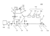
- FIG. 7 is a schematic diagram of a filtration apparatus according to Embodiment 4 of the present invention.
- symbol is provided to the same structural member as the filtration processing apparatus 100,200,300 which concerns on Embodiment 1 thru
- the filtration processing apparatus 400 in FIG. 7 includes a filtration unit 101, an ozone-containing liquid generator 102 that generates an ozone-containing liquid used for cleaning, and a first unit that separates the ozone-containing liquid after being used for cleaning into a gas and a liquid.
- a gas-liquid separator 103 a liquid supply source 108 in which a liquid such as water to be treated is stored, and a pumping unit 110 that pumps the liquid, and the filter unit 101 is washed with an ozone-containing liquid.
- the ozone-containing liquid generator 102 includes an ozone-containing liquid generation unit 112, a liquid supply source 109 in which the liquid supplied to the ozone-containing liquid generation unit 112 is stored, and a pumping unit 111 capable of pumping the liquid.
- the liquid stored in the liquid supply source 109 by the pumping unit 111 is supplied to the ozone-containing liquid generation unit 112, and thereby the ozone-containing liquid generation unit 112 generates an ozone-containing liquid.
- the generated ozone-containing liquid is supplied to the pipe d.
- generation part 112 is comprised by the thing of the form shown in FIG.3 and FIG.4, for example.
- the liquid supply source 109 plays a role as a liquid storage tank capable of storing a liquid, is connected to a pipe g including a pressure feeding unit 111, and supplies liquid such as water to the ozone-containing liquid generation unit 112. Supply.
- the liquid supply source 109 is connected to a pipe k communicating with the pipe b, and a liquid such as water flowing through the pipe b is introduced into the liquid supply source 109 through the pipe k.
- the first gas-liquid separator 103 a general gas-liquid separator having a function of separating the introduced gas-liquid mixture into gas and liquid can be used.
- the first gas-liquid separator 103 is formed in the shape of a cylindrical liquid storage tank that stores liquid, or in a structure in which a gas-liquid separator is formed in a pipe.
- the gas-liquid separator 103 is provided so as to be connected to a pipe c communicating with the pipe a, whereby the ozone-containing liquid after being used for cleaning is introduced into the first gas-liquid separator 103.
- the first gas-liquid separator 103 is connected to a pipe m communicating with the pipe b, whereby the pipe b removes the first solution to be treated such as water after being filtered in the filtration unit 101.
- the gas-liquid separator 103 can be led out.
- the ozone-containing liquid is attached to the surface of the filtration unit 101.
- the state in which the ozone-containing liquid is stored in the filtration treatment tank 21 in the state after the filtration unit 101 is washed with the ozone-containing liquid. Become. Therefore, when the filtration process is started immediately after the cleaning process, the ozone-containing liquid remaining in the filtration unit 101 may be mixed with the solution to be treated.
- a method such as decomposing ozone contained in the ozone-containing liquid and starting the filtration process until a certain time elapses after the cleaning process is completed is adopted.
- a certain amount of the solution to be treated after the filtration process is performed in the filtration unit 101 via the pipe m is the first gas-liquid separator.
- the ozone-containing liquid introduced into the first gas-liquid separator 103 is separated into liquid and gas in the first gas-liquid separator 103, and the gas containing ozone gas is filtered from the gas outlet 105. Derived out of 400.
- the gas containing ozone gas may be configured to be led out from the gas outlet 105 to the outside of the filtration apparatus 400 via the ozone filter 106.
- the ozone filter 106 is composed of paper or aluminum having an ozone decomposing catalyst attached in a lattice shape, and decomposes ozone gas passing through the ozone filter 106. Therefore, by providing the ozone filter 106, the gas can be safely discharged from the gas outlet 105.
- the ozone solution after the gas-liquid separation is stored in the first gas-liquid separator 103 or led out of the filtration apparatus 400 from the liquid outlet 107.
- the first gas-liquid separator 103 may store a certain amount of ozone gas, and the ozone gas may be naturally decomposed and then led out of the filtration apparatus 400.
- the gas outlet 105 may not be provided with the ozone filter 106, and the gas outlet 105 and the ozone-containing liquid generator 112 may be connected via a pipe.
- the ozone-containing liquid generation unit 112 is used as the ozone-containing liquid generation unit 112, the gas outlet 105 and the pipe e are connected, and a gas containing ozone gas is introduced into the ozone-containing liquid generation unit 112a.
- You may comprise.
- a gas containing ozone gas is introduced into the ozone-containing liquid generator 112b.
- the pipe c is provided with an on-off valve V4, and the pipe m is provided with an on-off valve V7, thereby controlling the flow rate of the liquid introduced into the first gas-liquid separator 103.
- the pipe m is connected to the first gas-liquid separator 103, but a part of the path of the pipe c is shared by connecting one end of the pipe m to the pipe c.
- the ozone-containing liquid may be introduced from the pipe b to the first gas-liquid separator 103 via the pipe m and the pipe c.
- the pipe d is provided with an on-off valve V2, whereby the supply amount of the ozone-containing liquid supplied to the filtration unit 101 can be controlled.
- the pipe a is provided with an on-off valve V1 between the liquid supply source 108 and a connection part C1 that is a part to which the pipe c is connected, and thereby the amount of the solution to be treated introduced into the filtration apparatus 400 can be reduced. It is possible to control.
- a pipe k connected to the liquid supply source 109 is connected to the pipe b, so that the pipe b has a function of supplying a liquid to the liquid supply source 109 via the pipe k.
- One end of the pipe k is connected to the pipe b at a position between the connection part C2 between the pipe d and the pipe b and the external port 104.
- the other end of the pipe k is connected to the liquid supply source 109. Thereby, the liquid can be introduced from the pipe b to the liquid supply source 109 through the pipe k.
- the piping b is provided with an on-off valve V3 between the connection portion C3 to the piping k and the external port 104, whereby the amount of liquid led out from the external port 104 can be controlled.
- the pipe b is provided with an on-off valve V6 between the connection part C2 with the pipe d and the connection part C3 with the pipe k, whereby the flow of the liquid passing through the on-off valve V6 can be controlled.
- the pipe b is connected to the pipe m provided with the on-off valve V7 in the connection part C4 located between the filtration part 101 and the connection part C2 of the pipe d. Liquid can be introduced into the first gas-liquid separator 103 from the pipe b.
- the filtration apparatus 400 has a function of filtering the solution to be treated by the filtration unit 101, a function of liquid supply processing to the liquid supply source 109 of the ozone-containing liquid generator 102, a function of cleaning processing of the filtration unit 101, And a rinsing function of the filtration unit.
- the filtration process is an operation of filtering the solution to be treated by the filtration unit 101.
- the on-off valve V1 is opened, the on-off valve V2 is closed, the on-off valve V3 is opened, the on-off valve V4 is closed, the on-off valve V6 is opened, and the on-off valve V7 is closed.
- a solution to be treated such as water is supplied from the liquid supply source 108 to the filtration unit 101.
- a solution to be treated such as water is supplied from the liquid supply source 108 to the filtration unit 101 via the pipe a. After the filtration process is performed in the filtration unit 101, the solution to be treated after the filtration process is supplied from the filtration unit 101. It is led out to the pipe b. Thereafter, the solution to be treated after the filtration process is led out of the filtration apparatus 400 through the external port 104 provided in the pipe b.
- the piping b forms a filtration path through which the solution to be treated after the filtration treatment flows.
- the filtration path means a path for leading the solution to be processed after the filtration process by the filtration unit 101 to the outside of the filtration apparatus 400.
- the liquid supply process to the liquid supply source 109 of the ozone-containing liquid generator 102 is an operation of supplying a solution to be processed such as water filtered by the filtration unit 101 to the liquid supply source 109 of the ozone-containing liquid generator 102. . Thereby, it is possible to store the liquid necessary for generating the ozone-containing liquid in the liquid supply source 109.
- the on-off valve V1 is opened, the on-off valve V2 is closed, the on-off valve V3 is closed, the on-off valve V4 is closed, and the on-off valve V6 is opened. Then, the on-off valve V7 is closed, and the solution to be treated is introduced from the liquid supply source 108 into the filtration unit 101.
- the introduced solution to be treated is introduced into the filtration unit 101 via the pipe a, and after filtration, the solution to be treated after filtration is led to the pipe b. Thereafter, the solution to be treated after filtration is introduced into the liquid supply source 109 along the pipe b and the pipe k. For this reason, the liquid supply path for supplying the liquid to the liquid supply source 109 is formed by the pipe b and the pipe k.
- the liquid supply path means a path for supplying the liquid after the filtering process to the liquid supply source of the ozone-containing liquid generator 102 to 109.
- the cleaning treatment is an operation of generating an ozone-containing liquid in the ozone-containing liquid generator 102 and cleaning the filter unit 101 or the piping using the generated ozone-containing liquid.
- the on-off valve V1 is closed, the on-off valve V2 is opened, the on-off valve V3 is closed, the on-off valve V4 is opened, the on-off valve V6 is closed, and the on-off valve V7 is closed.
- the ozone-containing liquid is introduced from the ozone-containing liquid generating unit 112 into the filtering unit 101 and cleaned.
- the ozone-containing liquid generated by the ozone-containing liquid generating unit 112 is introduced into the pipe b through the pipe d. Thereafter, the ozone-containing liquid is introduced into the filtration unit 101 via the pipe b, and the filtration unit 101 is washed.
- the ozone-containing liquid after being used for cleaning follows the pipe a and the pipe c as a waste ozone-containing liquid and is introduced into the first gas-liquid separator 103. Thereafter, the waste ozone-containing liquid is separated into gas and liquid in the first gas-liquid separator 103, and the gas containing ozone gas is led out from the gas outlet 105. For this reason, the path
- a drainage path through which the waste ozone-containing liquid used for cleaning is drained is formed by the path leading from the filtration part 101 of the pipe a to the connection part C1 and the pipe c.
- the cleaning path means a path for allowing the cleaning liquid to flow to the filtration unit 101
- the drainage path means that the waste ozone-containing liquid used for cleaning the filtering unit 101 is drained to the outside of the filtration processing apparatus 200. Means a route.
- the rinsing process of the filtration part is a process of removing the ozone-containing liquid adhering to the filtration part 101 during the cleaning process or the ozone-containing liquid stored in the filtration treatment tank 21 of the filtration part 101.
- the on-off valve V1 is opened, the on-off valve V2 is closed, the on-off valve V3 is closed, the on-off valve V4 is closed, and the on-off valve V6 is closed.
- V7 is opened, and the solution to be treated is introduced from the liquid supply source 108 into the filtration apparatus 400.
- the solution to be treated such as water supplied from the liquid supply source 108 to the filtration unit 101 via the pipe a removes the ozone-containing liquid adhering to the filtration unit 101 or is stored in the filtration treatment tank 21 of the filtration unit 101.
- the liquefied ozone-containing liquid is replaced with the solution to be treated, and the removed or replaced ozone-containing liquid is introduced into the first gas-liquid separator 103 via the pipe b and the pipe m, and the first gas-liquid separator It is led out of the filtration processing apparatus 400 from the liquid outlet 107 of 103.
- a path through which the ozone-containing liquid remaining in the filtration part 101 is drained is formed by the path from the filtration part 101 of the pipe b to the connection part C4 and the pipe m.
- the time of the rinse process which can remove an ozone containing liquid suitably with the shape of the filtration part 101, a magnitude
- 100, 200, 300, 400 Filtration processing device 101 Filtration unit, 102 Ozone-containing liquid generator, 103 First gas-liquid separator, 104 External port, 105 Gas outlet, 106 Ozone filter, 108, 109 Liquid supply source 110, 111 pressure feeding part, 112 ozone-containing liquid generating part, 113 check valve, 201 ozone generator, 202 gas-liquid mixer, 208 second gas-liquid separator, 212 gas introducing part, 21 filtration treatment tank, 22 Filtration membrane, 23 partition plate, V1, V2, V3, V4, V5, V6, V7 on / off valve, C1, C2, C3, C4, C5, C6 connection part.
Landscapes
- Chemical & Material Sciences (AREA)
- Chemical Kinetics & Catalysis (AREA)
- Life Sciences & Earth Sciences (AREA)
- Hydrology & Water Resources (AREA)
- Engineering & Computer Science (AREA)
- Environmental & Geological Engineering (AREA)
- Water Supply & Treatment (AREA)
- Organic Chemistry (AREA)
- Treatment Of Water By Oxidation Or Reduction (AREA)
- Separation Using Semi-Permeable Membranes (AREA)
- Physical Water Treatments (AREA)
Abstract
La présente invention concerne un appareil de filtration (100) comprenant une unité de filtration (101) utilisable en vue de la filtration d'un liquide, ledit appareil de filtration étant conçu de façon à ce qu'il soit possible de nettoyer l'unité de filtration (101) au moyen d'un liquide contenant de l'ozone. Ledit appareil de filtration comprend également un générateur de liquide contenant de l'ozone (102) qui génère le liquide contenant de l'ozone ; un conduit de nettoyage à travers lequel le liquide contenant de l'ozone est acheminé du générateur de liquide contenant de l'ozone (102) à l'unité de filtration (101) ; un conduit d'évacuation à travers lequel le liquide contenant de l'ozone est évacué après son utilisation en vue du nettoyage de l'unité de filtration (101) ; et un séparateur gaz-liquide (103) relié au conduit d'évacuation. Cela permet d'éviter la libération de concentrations élevées de gaz ozone dans l'atmosphère.
Applications Claiming Priority (2)
| Application Number | Priority Date | Filing Date | Title |
|---|---|---|---|
| JP2011-109346 | 2011-05-16 | ||
| JP2011109346A JP2012239936A (ja) | 2011-05-16 | 2011-05-16 | 浄水処理方法及び装置 |
Publications (1)
| Publication Number | Publication Date |
|---|---|
| WO2012157668A1 true WO2012157668A1 (fr) | 2012-11-22 |
Family
ID=47176985
Family Applications (1)
| Application Number | Title | Priority Date | Filing Date |
|---|---|---|---|
| PCT/JP2012/062500 Ceased WO2012157668A1 (fr) | 2011-05-16 | 2012-05-16 | Appareil de filtration et procédé de nettoyage d'un appareil de filtration |
Country Status (2)
| Country | Link |
|---|---|
| JP (1) | JP2012239936A (fr) |
| WO (1) | WO2012157668A1 (fr) |
Families Citing this family (2)
| Publication number | Priority date | Publication date | Assignee | Title |
|---|---|---|---|---|
| SG11201608368QA (en) * | 2014-04-10 | 2016-11-29 | Mitsubishi Electric Corp | Water treatment method and water treatment apparatus each using membrane |
| CN108697989B (zh) * | 2016-03-04 | 2019-09-27 | 三菱电机株式会社 | 膜过滤装置、过滤膜清洗方法以及过滤膜的制造方法 |
Citations (3)
| Publication number | Priority date | Publication date | Assignee | Title |
|---|---|---|---|---|
| JP2002079064A (ja) * | 2000-09-11 | 2002-03-19 | Isomura Housui Kiko Kk | 水処理の方法 |
| JP2002210339A (ja) * | 2001-01-19 | 2002-07-30 | Daikin Ind Ltd | オゾン水生成装置 |
| JP2005034694A (ja) * | 2003-07-16 | 2005-02-10 | Toray Ind Inc | 膜の洗浄方法およびろ過装置 |
-
2011
- 2011-05-16 JP JP2011109346A patent/JP2012239936A/ja active Pending
-
2012
- 2012-05-16 WO PCT/JP2012/062500 patent/WO2012157668A1/fr not_active Ceased
Patent Citations (3)
| Publication number | Priority date | Publication date | Assignee | Title |
|---|---|---|---|---|
| JP2002079064A (ja) * | 2000-09-11 | 2002-03-19 | Isomura Housui Kiko Kk | 水処理の方法 |
| JP2002210339A (ja) * | 2001-01-19 | 2002-07-30 | Daikin Ind Ltd | オゾン水生成装置 |
| JP2005034694A (ja) * | 2003-07-16 | 2005-02-10 | Toray Ind Inc | 膜の洗浄方法およびろ過装置 |
Also Published As
| Publication number | Publication date |
|---|---|
| JP2012239936A (ja) | 2012-12-10 |
Similar Documents
| Publication | Publication Date | Title |
|---|---|---|
| JP5037457B2 (ja) | 飲料用水濾過システム | |
| KR20210134371A (ko) | 물로부터의 난분해성 유기 화합물들의 제거를 위한 시스템 및 방법 | |
| CN115121124A (zh) | 过滤膜的清洗方法及清洗装置、以及水处理系统 | |
| KR20150100667A (ko) | 밸러스트수 처리 장치 및 밸러스트수 처리 장치의 역세정 방법 | |
| CN110709153B (zh) | 水处理膜的清洁装置、清洁方法以及水处理系统 | |
| WO2013111826A1 (fr) | Procédé de dessalement et dispositif de dessalement | |
| WO2019039155A1 (fr) | Appareil de nettoyage de membrane de traitement d'eau et procédé de nettoyage de membrane | |
| WO2007142068A1 (fr) | Appareil de purification d'eau de ballast de navire | |
| JP2014018782A (ja) | バラスト水処理用濾過膜の洗浄システム及び洗浄方法 | |
| KR20150080515A (ko) | 제탁막 모듈의 운전 방법 | |
| JP5227478B1 (ja) | 海苔製造システム | |
| KR20140128841A (ko) | 막모듈의 교차 정수 및 세정 장치와 이의 운전방법 | |
| JP2009233623A (ja) | 水処理ろ過装置 | |
| JP2002282860A (ja) | プール水浄化処理方法および装置 | |
| JP2002248324A (ja) | 膜分離装置及びその逆洗方法 | |
| JP2827877B2 (ja) | 膜分離装置及びその洗浄方法 | |
| WO2012157668A1 (fr) | Appareil de filtration et procédé de nettoyage d'un appareil de filtration | |
| JP5793713B2 (ja) | バラスト水製造装置 | |
| JP4454922B2 (ja) | 中空糸型分離膜を用いた濾過装置の制御方法 | |
| JP2011041907A (ja) | 水処理システム | |
| WO2024154319A1 (fr) | Dispositif de nettoyage de membrane de filtration | |
| JP2009082858A (ja) | 濾過膜の洗浄方法 | |
| KR102312754B1 (ko) | 세라믹 분리막의 막여과 공정과 오존 산화반응 공정이 결합된 일체형 수처리 장치 | |
| JP2013252478A (ja) | 油分含有排水の処理方法及び処理装置 | |
| JP2007061697A (ja) | 分離膜の洗浄方法、ならびに有機性汚水処理装置 |
Legal Events
| Date | Code | Title | Description |
|---|---|---|---|
| 121 | Ep: the epo has been informed by wipo that ep was designated in this application |
Ref document number: 12785071 Country of ref document: EP Kind code of ref document: A1 |
|
| NENP | Non-entry into the national phase |
Ref country code: DE |
|
| 122 | Ep: pct application non-entry in european phase |
Ref document number: 12785071 Country of ref document: EP Kind code of ref document: A1 |