WO2012157675A1 - 建設機械用アーム - Google Patents
建設機械用アーム Download PDFInfo
- Publication number
- WO2012157675A1 WO2012157675A1 PCT/JP2012/062514 JP2012062514W WO2012157675A1 WO 2012157675 A1 WO2012157675 A1 WO 2012157675A1 JP 2012062514 W JP2012062514 W JP 2012062514W WO 2012157675 A1 WO2012157675 A1 WO 2012157675A1
- Authority
- WO
- WIPO (PCT)
- Prior art keywords
- plate
- welding
- thick
- upper plate
- joined
- Prior art date
- Legal status (The legal status is an assumption and is not a legal conclusion. Google has not performed a legal analysis and makes no representation as to the accuracy of the status listed.)
- Ceased
Links
Images










Classifications
-
- E—FIXED CONSTRUCTIONS
- E02—HYDRAULIC ENGINEERING; FOUNDATIONS; SOIL SHIFTING
- E02F—DREDGING; SOIL-SHIFTING
- E02F9/00—Component parts of dredgers or soil-shifting machines, not restricted to one of the kinds covered by groups E02F3/00 - E02F7/00
- E02F9/14—Booms only for booms with cable suspension arrangements; Cable suspensions
-
- E—FIXED CONSTRUCTIONS
- E02—HYDRAULIC ENGINEERING; FOUNDATIONS; SOIL SHIFTING
- E02F—DREDGING; SOIL-SHIFTING
- E02F3/00—Dredgers; Soil-shifting machines
- E02F3/04—Dredgers; Soil-shifting machines mechanically-driven
- E02F3/28—Dredgers; Soil-shifting machines mechanically-driven with digging tools mounted on a dipper- or bucket-arm, i.e. there is either one arm or a pair of arms, e.g. dippers, buckets
- E02F3/36—Component parts
- E02F3/38—Cantilever beams, i.e. booms;, e.g. manufacturing processes, forms, geometry or materials used for booms; Dipper-arms, e.g. manufacturing processes, forms, geometry or materials used for dipper-arms; Bucket-arms
Definitions
- the present invention relates to an arm for a construction machine suitably used for a working device mounted on a construction machine such as a hydraulic shovel, for example.
- a hydraulic shovel which is a typical example of a construction machine, includes a self-propelled lower traveling body, and an upper revolving body rotatably provided on the lower traveling body.
- a working device for excavating soil and the like is provided so as to be capable of raising and lowering.
- the working device of the hydraulic shovel is normally provided with a boom rotatably mounted on the pivot frame on the proximal side, an arm rotatably mounted on the distal end side of the boom, and the distal end side of the arm It is roughly configured by a work tool such as a rotatably mounted bucket and the boom, an arm, a boom cylinder for driving the bucket, an arm cylinder, and a bucket cylinder.
- the arm that constitutes such a working device is usually formed as a long welded structure with a total length of several meters. That is, the arms are: left and right side plates, an upper plate joined by welding to the upper ends of the left and right side plates, a lower plate joined by welding to the lower ends of the left and right side plates, and left And a rear plate joined by welding to the rear end side of the right side plate and the upper plate.
- the arm is a box-shaped structure having a closed cross-sectional structure having a square cross section.
- An arm cylinder bracket in which a boom connection boss connected with a connection pin on the tip end side of the boom is provided on the rear lower side of the arm and an arm cylinder is connected with the connection pin on the rear end side of the arm Is provided.
- a bucket cylinder bracket to which a bucket cylinder is connected using a connection pin is provided on the rear upper side of the arm.
- a bucket connection boss is provided at the front end of the arm, in which the buckets are connected using a connection pin (Patent Document 1).
- the boom connection boss, the arm cylinder bracket and the bucket cylinder bracket are provided on the rear side of the arm, the strength required for the arm is large on the rear side and small on the front side.
- the upper plate and the lower plate are usually formed using a single plate material such as a steel plate having a uniform plate thickness. Therefore, on the front side of the arm, the plate thickness of the upper plate and the lower plate tends to be too thick with respect to the required strength, and there is a problem that the weight of the entire arm becomes larger than necessary.
- the present invention has been made in view of the problems of the prior art described above, and it is an object of the present invention to provide an arm for a construction machine capable of reducing the overall weight while securing necessary strength.
- the present invention relates to left and right side plates, an upper plate joined by welding to the upper ends of the left and right side plates, and joined by welding to the lower ends of the left and right side plates.
- a boom connection boss is provided below the rear of the left and right side plates and is welded to the left and right side plates, the rear end of the lower plate, and the front end of the rear plate by welding.
- An arm for a construction machine comprising a bucket connecting boss joined by welding at the front end of the side plate, the upper plate and the lower plate, and a pair of left and right bucket cylinder brackets joined by welding to the outer surface of the upper plate. Applies to
- the upper plate is a rear thick upper plate located on the rear side and made of a thick plate material, and a front thin plate located on the front side of the rear thick upper plate made of a thin plate material
- the bucket cylinder bracket is formed by joining two members with the upper plate, and the bucket cylinder bracket is configured to be joined to the outer surface of the rear thick upper plate.
- the rear side requiring high strength is constituted by the rear thick upper plate having a large thickness
- the front side not requiring large strength as compared to the rear side Can be constituted by a thin front plate with a small thickness.
- the feature of the present invention is that the lower plate is located on the rear side and a thick lower plate is made of a plate material, and the rear thick plate is located on the front side of the lower plate and a thin plate plate is made of a thinner plate.
- the boom connection boss is formed by joining two members with the plate, and the boom connection boss is configured to be joined to the rear end of the rear thick lower plate.
- the rear side requiring high strength is constituted by the rear thick lower plate having a large thickness
- the front side not requiring high strength as compared to the rear side Can be constituted by a thin front plate with a small thickness.
- the feature of the present invention is that the upper plate is located on the rear side and a thick upper plate is made of a plate material, and the rear thick upper plate is located on the front side of a thin plate material.
- the lower plate is formed by joining two members with a plate, and the lower plate is located on the rear side and is a rear thick lower plate made of a thick plate material, and is positioned on the front side of the rear thick lower plate to have a plate thickness
- the bucket cylinder bracket is formed by joining two members with a front thin lower plate made of thin plate members, and the bucket cylinder bracket is connected to the outer surface of the rear thick upper plate, and the boom connection boss is formed after the rear thick lower plate. It is in the configuration to be joined to the end.
- the rear side requiring the greater strength is constituted by the rear thick upper plate and the rear thick lower plate having a large thickness, and compared with the rear side.
- the front side which does not require a large strength can be constituted by the front thin upper plate and the front thin lower plate having a small thickness.
- the upper plate is a rear thick upper plate which is located on the rear side and is made of a thick plate material, and a front thin plate which is located on the front side of the rear thick upper plate and is made a thin plate material
- the lower plate is formed by joining two members with the upper plate, and the lower plate is a rear thick lower plate located on the rear side and a thick lower plate, and a lower plate located on the front side of the rear thick lower plate
- the left and right side plates are formed by joining two members with a front thin lower plate made of a thin plate material, and the left and right side plates are positioned on the rear side and a rear thick side plate made of a thick plate and the rear side plate.
- the bucket cylinder bracket is formed on a front side of a thick side plate by joining two members with a front thin side plate made of a thin plate material, and the bucket cylinder bracket is joined to the outer surface of the rear thick upper plate
- the boom connection boss is configured to be joined to the rear end of the rear thick lower plate, and the joint between the rear thick side plate and the front thin side plate is the upper end thereof It joined to a thickness upper plate after the is to the lower end and configured to be joined to the thick lower plate after the.
- the left and right side plates, the upper plate, and the lower plate, which constitute the arm can be thick on the rear side and thin on the front side.
- the upper end of the joint between the rear thick side plate and the front thin side plate is joined to the rear thick upper plate
- the lower end of the joint between the rear thick side plate and the front thin side plate is joined to the rear thick lower plate.
- the strength of the joint between the side plate and the front thin side plate can be enhanced, and the strength of the entire arm can be enhanced.
- an inner partition wall for reinforcement is provided between the inner surface side of the rear thick upper plate and the boom connection boss.
- the inner partition wall connects the left and right side plates, the rear end of the lower plate, the boom connection boss joined to the front end of the rear plate, and the rear thick upper plate to each other
- the rear end of the arm provided with the boom connection boss and the bucket cylinder bracket can be strengthened.
- the rear plate is formed as a thick rear plate using a plate material having a plate thickness equal to or more than the rear thick upper plate and the rear thick side plate, and the thick rear plate is formed of the left and right
- the rear thick side plate is joined to the rear end of the rear thick side plate and the rear end of the rear thick upper plate, and the front end of the thick rear plate is joined to the boom connection boss.
- the strength of the rear side of the arm is further enhanced by joining the front end of the thick rear plate having the same thickness or more as the rear thick upper plate and the left and right rear thick side plates to the boom connection boss. be able to.
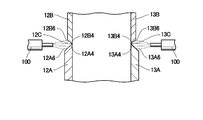
- the front end of the rear thick side plate and the rear end of the front thin side plate are respectively provided with grooves extending upward and downward by cutting out without root face, and the groove of the rear thick side plate and By abutting the groove of the front thin side plate, a V-shaped groove without a root face and no gap is formed, and between the rear thick side plate and the front thin side plate at the position of the V-shaped groove. Welding bead to form a weld bead.
- a backing material is not disposed on the back side of the V-shaped groove.
- Complete welding can be performed on the butt portion of the rear thick side plate and the front thin side plate. Therefore, the workability when performing butt welding between the rear thick side plate and the front thin side plate can be enhanced.
- the bucket connecting boss is provided with hooks located on the left and right sides of the cylindrical boss and extending toward the left and right side plates, and the front ends of the left and right side plates are
- An upper and a lower extending groove are respectively provided by cutting out without a root face, and a rear end of the left and right buttocks of the bucket connecting boss is opened by extending a lower and a lower end by cutting out without a root face.
- a V-shaped groove having no root face and no gap is formed by providing a tip and matching the groove of the left and right side plates with the groove of the left and right buttocks.
- a welding bead is formed by welding between the left and right side plates and the left and right ridges at the position of the forming groove.
- the front end of the rear thick upper plate and the rear end of the front thin upper plate are provided with grooves extending in the left and right directions by cutting out without root face, respectively.
- a V-shaped groove without a root face and no gap is formed, and the rear thick plate and the front are formed at the position of the V-shaped groove.
- a welding bead is formed by applying a weld between the thin upper plate and the thin upper plate.
- the front end of the rear thick lower plate and the rear end of the front thin lower plate are provided with grooves extending in the left and right directions by cutting out without root face, respectively.
- a V-shaped groove without a root face and without a gap is formed, and the back thick lower plate and the above-mentioned rear thick lower plate at the position of the V-shaped groove.
- the welding bead is formed by welding between the front thin lower plate and the lower thin plate.
- the groove angle of the V-shaped groove is set to be in the range of 43 degrees or more and 90 degrees or less. According to this configuration, when two members are butt-welded using means such as arc welding, arc heat is sufficiently supplied to the groove of one member butted and the groove of the other member. The two members can be melted in over the entire thickness. Further, by setting the groove angle of the V-shaped groove of the butt portion of two members to 90 degrees or less, the inside of the V-shaped groove can be filled with the molten metal without excess and deficiency, and the two members are smoothly continuous. Weld bead can be formed.
- a flat auxiliary welding member is provided on the outer surface on the rear side of the upper plate so as to surround a welded portion between the left and right bucket cylinder brackets and the upper plate, and the auxiliary welding member
- the weld bead is formed by applying a fillet weld to the periphery of the.
- the auxiliary welding member by providing the auxiliary welding member, it is possible to partially increase the thickness of the portion of the upper plate to which the bucket cylinder brackets are joined. As a result, it is possible to suppress large deformation of the upper plate or each bucket cylinder bracket due to the load acting on each bucket cylinder bracket, and to improve the durability of the entire arm. Furthermore, by performing fillet welding around the auxiliary welding member, the welded portion between each bucket cylinder bracket and the upper plate can be reinforced by the weld bead formed between the auxiliary welding member and the upper plate. . For this reason, the stress which arises in the welding part of each bucket cylinder bracket and a top plate can be reduced. As a result, the strength of the upper plate and each bucket cylinder bracket can be increased without increasing the thickness of the upper plate and each bucket cylinder bracket, and the weight reduction of the entire arm can be achieved while securing the required strength. Can.
- a reinforcing internal partition wall is provided between the boom connection boss and a position on the inner surface side of the upper plate and in front of the position of the connection pin provided on the bucket cylinder bracket,
- the rear end of the auxiliary welding member is configured to extend rearward beyond the upper end position of the inner partition wall.
- the gap between the bucket cylinder bracket and the auxiliary welding member on the outer surface of the upper plate is embedded by the welding bead of the bucket cylinder bracket and the welding bead of the auxiliary welding member. It is to have done.
- the weld bead formed between the bucket cylinder bracket and the upper plate and the weld bead formed between the auxiliary welding member and the upper plate can be integrated. As a result, the bonding strength of the bucket cylinder bracket to the upper plate can be enhanced.
- the auxiliary welding member is formed in an M shape in a plan view, and a notch cut in a concave shape toward the rear is provided on the front side of the M-shaped auxiliary welding member. It is in. According to this configuration, by performing fillet welding around the auxiliary welding member, a large welding length can be secured. As a result, the joint strength of the auxiliary welding member to the upper plate can be enhanced, and the strength of the weld between the upper plate and the bucket cylinder bracket reinforced by the auxiliary welding member can be further enhanced.
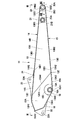
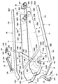
- FIG. 3 is a plan view of the arm as viewed in the direction of arrows III-III in FIG. 2;
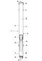
- FIG. 4 is a cross-sectional view of the arm as viewed in the direction of arrows IV-IV in FIG. 3;
- FIG. 5 is an enlarged cross-sectional view showing a rear thick upper plate, a front thin upper plate, a rear thick lower plate, a front thin lower plate, and a rear thick plate in FIG. 4.
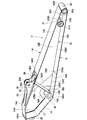
- FIG. 6 is a cross-sectional view of left and right side plates, a rear thick upper plate, and a rear thick lower plate as viewed in the direction of arrows VI-VI in FIG. 5; It is a perspective view which shows the inside of an arm in the state which removed the right side board. It is an exploded perspective view which disassembles and shows a side plate, an upper plate, a lower plate, a back plate, a boom connection boss, an arm cylinder bracket, and a bucket cylinder bracket which constitute an arm.
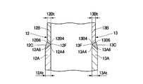
- FIG. 6 is a cross-sectional view of a joint portion between a rear thick side plate and a front thin side plate as viewed in the direction of arrows IX-IX in FIG.
- FIG. 3 is a cross-sectional view of a junction between a front thin side plate and a bucket connecting boss, as viewed in the direction of arrows XIII-XIII in FIG. 2; It is sectional drawing which shows the groove of a front thin side plate, and the groove of the buttocks of a bucket connecting boss.
- FIG. 26 is a cross-sectional view of the welding portion of the upper plate, the bucket cylinder bracket, and the auxiliary welding member, as viewed in the direction of arrows XXVI-XXVI in FIG. 25. It is sectional drawing which shows the state which arrange
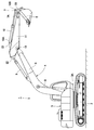
- the hydraulic shovel 1 indicates a hydraulic shovel as a representative example of a construction machine.
- the hydraulic shovel 1 includes a self-propelled crawler type lower traveling body 2 and an upper swing body 3 rotatably mounted on the lower traveling body 2.
- a working device 4 is provided on the front side of a swing frame 3A, which is a base of the upper swing body 3, so as to be capable of raising and lowering.
- the working device 4 has a boom 5 whose proximal end is pin-pind movably up and down on the front side of the swing frame 3A, and an arm 11 described below whose base end is pivotally pin-connected to the distal end of the boom 5
- a bucket 6 rotatably pin-connected to the tip of the arm 11 and a bucket link 7 provided between the tip of the arm 11 and the bucket 6 are provided.
- the working device 4 rotates the boom cylinder 8 that raises and lowers the boom 5 with respect to the turning frame 3A, the arm cylinder 9 that rotates the arm 11 with respect to the boom 5, and the bucket 6 with respect to the arm 11 And a bucket cylinder 10.
- the bucket link 7 has a rear link 7A having one end connected to the tip end of the arm 11, and a front link 7B having one end connected to the other end of the rear link 7A and the other end connected to the bucket 6. It is configured.
- the bottom side of the bucket cylinder 10 is attached to a bucket cylinder bracket 23 of an arm 11 described later using a connection pin 10A.
- the rod side of the bucket cylinder 10 is connected to the connecting portion of the rear link 7A of the bucket link 7 and the front link 7B using a connecting pin 10B.
- Reference numeral 11 denotes an arm rotatably attached to the tip of the boom 5.
- the arm 11 is formed as a long box-shaped structure extending forward and backward as a whole, and is pivoted up and down with respect to the boom 5 by the arm cylinder 9.
- the arm 11 is formed by left and right side plates 12 and 13, an upper plate 14, a lower plate 15, and a thick rear plate 16 which will be described later, and the arm 11 has a square cross section as a whole. It has a box-shaped structure with a closed cross-sectional structure.
- a boom connection boss 18, an arm cylinder bracket 22, a bucket cylinder bracket 23, and the like, which will be described later, are provided on the rear side (the boom 5 side) of the arm 11.
- a bucket connection boss 20, a rear link connection boss 21 and the like described later are provided on the front side (the bucket 6 side) of the arm 11.
- Reference numeral 12 denotes a left side plate which constitutes the left side surface of the arm 11.
- the left side plate 12 extends in the front and rear directions while facing the right side plate 13 described later in the left and right directions.
- the left side plate 12 includes two of the rear thick side plate 12A positioned on the rear side in the front and rear direction and the front thin side plate 12B positioned on the front side in the front and rear direction. It is formed by joining members.
- a boom connection boss 18 described later is fixed to the rear thick side plate 12A, and a bucket connection boss 20 and a rear link connection boss 21 described later are fixed to the front thin side plate 12B.
- the rear thick side plate 12A is formed using a plate material such as a thick steel plate material, and is formed by the upper plate joint portion 12A1, the lower plate joint portion 12A2, the rear plate joint portion 12A3, and the front thin side plate joint portion 12A4. It has an enclosed hexagonal shape.
- the front thin side plate bonding portion 12A4 extends obliquely forward from the upper plate bonding portion 12A1 to the lower plate bonding portion 12A2, thereby increasing the length of the bonding portion between the rear thick side plate 12A and the front thin side plate 12B. It is configured to secure.
- a boom connection boss joint groove 12A5 notched in an arc shape for joining the flange portion 18B of the boom connection boss 18 is provided at a corner where the lower plate joint portion 12A2 and the rear plate joint portion 12A3 intersect. .
- a groove 12A6 is provided at the front end of the rear thick side plate 12A, and the groove 12A6 is abutted with the rear side groove 12B6 of the front thin side plate 12B described later.
- the groove 12A6 is formed by cutting out the edge of the front thin side plate bonding portion 12A4 constituting the rear thick side plate 12A by inclining toward the outer surface side. ing.
- the groove 12A6 is formed as a uniform inclined surface having no root face, and is provided over the entire area of the front thin side plate joint portion 12A4.
- the front thin side plate 12B is formed using a plate material such as a steel plate material thinner than the rear thick side plate 12A, and the upper plate joint portion 12B1, the lower plate joint portion 12B2, and the bucket connecting boss joint portion 12B3 , And the rear thick side plate joint portion 12B4 has a rectangular shape.
- the rear thick side plate joint portion 12B4 extends obliquely forward from the upper plate joint portion 12B1 to the lower plate joint portion 12B2.
- a rear link connection boss joint hole 12B5 formed of a circular hole for joining the flange portion 21B of the rear link connection boss 21 is provided.
- a rear groove 12B6 is provided at the rear end of the front thin side plate 12B, and the rear groove 12B6 is abutted with the groove 12A6 of the rear thick side plate 12A.
- the rear groove 12B6 is cut out by inclining the end edge of the rear thick side plate bonding portion 12B4 that constitutes the front thin side plate 12B toward the outer surface side. It is formed.
- the groove 12B6 is formed as a uniform inclined surface having no root face, and is provided over the entire area of the rear thick side plate joint portion 12B4.
- a front side groove 12B7 is provided at the front end of the front thin side plate 12B, and the front side groove 12B7 is abutted with a groove 20B1 provided in a port portion 20B of a bucket connecting boss 20 described later.
- the front groove 12B7 is cut out by inclining the end edge portion of the bucket connecting boss joint portion 12B3 constituting the front thin side plate 12B toward the inner surface side. , It is formed as a uniform slope without root face.
- the thickness 12At and the thickness 12Bt are different.
- the relationship is set as shown in the following equation 1.
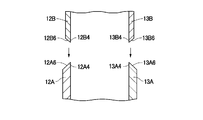
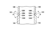
- the inner surface of the rear thick side plate 12A and the front thin side plate 12A are abutted by butting together the groove 12A6 of the rear thick side plate 12A and the rear side groove 12B6 of the front thin side plate 12B without a gap. It forms the same plane without a level
- the outer surface of the rear thick side plate 12A and the outer surface of the front thin side plate 12B form a step according to the plate thickness difference, and a V-shaped groove 12C having no root face and no gap is formed in this step portion.
- the groove angle of the V-shaped groove 12C is ⁇
- the groove angle ⁇ is set in the range of the following formula 2.
- butt welding is performed using a welding torch 100 or the like at the position of the V-shaped groove 12C, the back thickness of the front thin side plate joint portion 12A4 of the rear thick side plate 12A and the front thin side plate 12B.
- the side plate joint portion 12B4 is joined in a completely welded state, and the left side plate 12 including the rear thick side plate 12A and the front thin side plate 12B is formed.
- the opening width of the V-shaped groove 12C is determined in accordance with the outer diameter of the welding torch 100.
- the groove angle ⁇ of the V-shaped groove 12C is determined based on the outer diameter of the welding torch 100, the thickness 12At of the rear thick side plate 12A and the thickness 12Bt of the front thin side plate 12B, and the required amount of welding beads. It is In this case, if the groove angle ⁇ is too small, the rear thick side plate 12A and the front thin side plate 12B will not be sufficiently melted, and if the groove angle ⁇ is too large, the amount of beads used will increase and welding workability will be improved. In order to decrease, it is desirable to set the groove angle ⁇ within the range of the above-mentioned equation 2.
- the groove angle ⁇ of V-shaped grooves 13C, 14C, 15C, 20D, and 20E described later is also set in the range of the above-mentioned number 2 similarly to the groove angle ⁇ of the V-shaped groove 12C.
- the reference numeral 13 denotes a right side plate constituting the right side surface of the arm 11, and the right side plate 13 has the same shape as the left side plate 12. That is, the right side plate 13 is formed by joining two members, a rear thick side plate 13A positioned on the rear side in the front and rear directions, and a front thin side plate 13B positioned on the front side in the front and rear directions.
- a boom connection boss 18 described later is fixed to the rear thick side plate 13A, and a bucket connection boss 20 and a rear link connection boss 21 described later are fixed to the front thin side plate 13B.
- the rear thick side plate 13A is formed using a plate material such as a thick steel plate material, and is formed by the upper plate joint portion 13A1, the lower plate joint portion 13A2, the rear plate joint portion 13A3, and the front thin side plate joint portion 13A4. It has an enclosed hexagonal shape.
- a boom connection boss joint groove 13A5 cut in an arc shape is provided at a corner where the lower plate joint portion 13A2 and the rear plate joint portion 13A3 intersect.
- a groove 13A6 is provided at the front end of the rear thick side plate 13A, and the groove 13A6 is abutted with the rear side groove 13B6 of the front thin side plate 13B described later.
- the groove 13A6 is a root by cutting the edge of the front thin side plate bonding portion 13A4 constituting the rear thick side plate 13A toward the outer surface side and cutting it out. It is formed as a uniform inclined surface with no face.
- the front thin side plate 13B is formed using a plate material such as a steel plate material thinner than the rear thick side plate 13A, and the upper plate joint portion 13B1, the lower plate joint portion 13B2, and the bucket connecting boss joint portion 13B3 , And the rear thick side plate joint portion 13B4 has a rectangular shape surrounded. Further, on the front end side of the front thin side plate 13B, a rear link connection boss joint hole 13B5 consisting of a circular hole is provided.
- a rear side groove 13B6 is provided at the rear end of the front thin side plate 13B, and the rear side groove 13B6 is abutted with the groove 13A6 of the rear thick side plate 13A.
- the rear side groove 13B6 is cut out by inclining the end edge of the rear thick side plate joint portion 13B4 constituting the front thin side plate 13B toward the outer surface side. , It is formed as a uniform slope without root face.
- a front side groove 13B7 is provided at the front end of the front thin side plate 13B, and the front side groove 13B7 is abutted with a groove 20C1 provided on the right flange 20C of the bucket connecting boss 20 described later.
- the front groove 13B7 is formed by cutting the edge of the bucket connecting boss joint portion 13B3 constituting the front thin side plate 13B toward the inner surface side and cutting it out. It is formed as a uniform slope without root face.
- the groove 13A6 of the rear thick side plate 13A and the rear side groove 13B6 of the front thin side plate 13B are butted without gaps (gaps) to form the inner surface of the rear thick side plate 13A and the front thin side plate 13B. It forms the same plane without a level difference with the inner surface.
- the outer surface of the rear thick side plate 13A and the outer surface of the front thin side plate 13B form a step according to the plate thickness difference, and there is no root face at this step portion. 13C is formed.
- butt welding is performed using a welding torch 100 or the like at the position of the V-shaped groove 13C.
- the front thin side plate joint portion 13A4 of the rear thick side plate 13A and the rear thick side plate joint portion 13B4 of the front thin side plate 13B are joined in a completely welded state, and the right side plate consisting of the rear thick side plate 13A and the front thin side plate 13B. 13 is formed.
- reference numeral 14 denotes a top plate which constitutes the upper surface of the arm 11.
- the upper plate 14 is joined to the upper ends of the left and right side plates 12 and 13 and extends in the front and rear directions.
- the upper plate 14 is formed by joining two members, a rear thick upper plate 14A positioned on the rear side in the front and rear directions, and a front thin upper plate 14B positioned on the front side in the front and rear directions. ing.
- a bucket cylinder bracket 23 described later is fixed to the rear thick upper plate 14A.
- the rear thick upper plate 14A is formed in a rectangular plate shape extending in the front and rear directions, using a plate material such as a thick steel plate, and the portion on the rear side of the bucket cylinder bracket 23 is slightly inclined downward. I am bent.
- the rear end edge of the rear thick upper plate 14A is a rear plate joint portion 14A1 joined to the thick rear plate 16 described later, and the front end edge of the rear thick upper plate 14A is a front thin upper portion bonded to the front thin upper plate 14B. It becomes board junction part 14A2.
- a bucket cylinder bracket 23 described later is joined to an outer surface 14A4 of the rear thick upper plate 14A, and an upper end 19A of an inner partition wall 19 described later is joined to an inner surface 14A5 of the rear thick upper plate 14A.
- a groove 14A3 is provided at the front end of the rear thick upper plate 14A, and the groove 14A3 is abutted with a groove 14B3 of a front thin upper plate 14B described later.
- the groove 14A3 is cut out by inclining the edge of the front thin upper plate bonding portion 14A2 constituting the rear thick upper plate 14A toward the outer surface 14A4.
- it is formed as a uniform inclined surface having no root face.
- the front thin upper plate 14B is formed in a rectangular flat plate shape extending in the front and rear directions, using a plate material such as a steel plate material thinner than the rear thick upper plate 14A.
- a rear end edge of the front thin upper plate 14B is a rear thick upper plate joint portion 14B1
- a front end edge of the front thin upper plate 14B is a bucket connecting boss joint portion 14B2 which is joined to a bucket connection boss 20 described later.
- a groove 14B3 is provided at the rear end of the front thin upper plate 14B, and the groove 14B3 is abutted with the groove 14A3 of the rear thick upper plate 14A.
- the groove 14B3 is formed by cutting the end edge of the rear thick upper plate bonding portion 14B1 constituting the front thin upper plate 14B toward the outer surface side. , It is formed as a uniform slope without root face.
- the inner surface 14A5 of the rear thick upper plate 14A and the front thin upper surface are matched by butting the groove 14A3 of the rear thick upper plate 14A and the groove 14B3 of the front thin upper plate 14B without a gap. It forms the same plane without a level difference with the inside of board 14B.
- a step corresponding to the thickness difference is formed between the outer surface 14A4 of the rear thick upper plate 14A and the outer surface of the front thin upper plate 14B.
- Form groove 14C is formed.
- butt welding is performed using a welding torch 100 or the like at the position of the V-shaped groove 14C.
- the front thin upper plate joint portion 14A2 of the rear thick upper plate 14A and the rear thick upper plate joint portion 14B1 of the front thin upper plate 14B are joined in a completely welded state, and the rear thick upper plate 14A and the front thin upper plate An upper plate 14 consisting of 14B is formed.
- reference numeral 15 denotes a lower plate which constitutes the lower surface of the arm 11.
- the lower plate 15 is joined to the lower ends of the left and right side plates 12 and 13 and extends in the front and rear directions.
- the lower plate 15 is formed by joining two members, a lower thickness lower plate 15A located on the rear side in the front and rear directions, and a front thin lower plate 15B located on the front side in the front and rear directions. ing.
- the rear thickness lower plate 15A is formed in a rectangular flat plate shape extending in the front and rear directions, using a plate material such as a thick steel plate material.
- the rear end edge of the rear thick lower plate 15A is a boom connection boss joint portion 15A1 joined to a boom connection boss 18 described later.
- the front end edge of the rear thick lower plate 15A is a front thin lower plate joint portion 15A2 joined to the front thin lower plate 15B.
- a groove 15A3 is provided at the front end of the rear thickness lower plate 15A, and the groove 15A3 is abutted with a groove 15B3 of the front thin lower plate 15B described later.
- the groove 15A3 is cut out by inclining the end edge of the front thin lower plate bonding portion 15A2 constituting the rear thick lower plate 15A toward the outer surface side. , It is formed as a uniform slope without root face.
- the front thin lower plate 15B is formed in a rectangular flat plate shape extending in the front and rear directions, using a plate material such as a steel plate material thinner than the rear thick lower plate 15A.
- the rear end edge of the front thin lower plate 15B is a rear thick lower plate joint portion 15B1.
- the front end edge of the front thin lower plate 15B is a bucket connecting boss joint portion 15B2 joined to a bucket connecting boss 20 described later.
- a groove 15B3 is provided at the rear end of the front thin lower plate 15B, and the groove 15B3 is abutted with the groove 15A3 of the rear thick lower plate 15A.
- the groove 15B3 is cut out by inclining the end edge of the rear thick lower plate joint portion 15B1 constituting the front thin lower plate 15B toward the outer surface side. , It is formed as a uniform slope without root face.
- the inner surface of the rear lower thickness plate 15A and the front thin lower plate are butted by abutting the groove 15A3 of the rear thickness lower plate 15A and the groove 15B3 of the front thin lower plate 15B without a gap. It forms the same plane without a level difference with the inner surface of 15B.
- the outer surface of the rear thick lower plate 15A and the outer surface of the front thin lower plate 15B form a step according to the plate thickness difference, and there is no root face and no gap at this step portion. Grooves 15C are formed.
- butt welding is performed using a welding torch 100 or the like at the position of the V-shaped groove 15C.
- the front thin lower plate joint portion 15A2 of the rear thick lower plate 15A and the rear thick lower plate joint portion 15B1 of the front thin lower plate 15B are joined in a completely welded state, and the rear thick lower plate 15A and the front thin lower plate A lower plate 15 consisting of 15B is formed.
- reference numeral 16 denotes a thick rear plate as a rear plate constituting the rear surface of the arm 11.
- the thick rear plate 16 is formed in a rectangular plate shape using a plate material such as a steel plate material, and a central portion in a length direction is bent in a mountain shape (see FIG. 5).
- the thickness 16t of the rear plate 16 is the thickness 12At of the rear thick side plate 12A constituting the left side plate 12, the thickness 13At of the rear thick side plate 13A constituting the right side plate 13, and the rear thickness upper side
- the thickness 14At of the plate 14A and the thickness 15At of the lower thickness plate 15A constituting the lower plate 15 have the same thickness or more than these thicknesses, and they are set as in the following equation 6.
- the thick rear plate 16 is joined to the rear end sides of the left and right side plates 12 and 13 and the upper plate 14 by welding, and closes the rear end of the hollow arm 11.
- the thick rear plate 16 constitutes the rear plate joint portion 12A3 of the rear thick side plate 12A constituting the left side plate 12, the rear plate joint portion 13A3 of the rear thick side plate 13A constituting the right side plate 13, and the upper plate 14 It is joined by welding to back board joined part 14A1 of back thick board 14A.
- the front end edge of the thick rear plate 16 is a boom connection boss joint portion 16A joined to a boom connection boss 18 described later.
- An arm cylinder bracket 22 described later is fixed to the outer surface of the thick rear plate 16.
- Fillet welding is applied between the upper plate joint portion 12A1 of the rear thick side plate 12A constituting the left side plate 12 and the upper plate 14. Similarly, fillet welding is applied between the upper plate joint portion 12B1 of the front thin side plate 12B and the upper plate 14. On the other hand, a fillet weld is applied between the upper plate joint portion 13A1 of the rear thick side plate 13A constituting the right side plate 13 and the upper plate 14. Similarly, fillet welding is applied between the upper plate joint portion 13B1 of the front thin side plate 13B and the upper plate 14. Thus, the upper plate 14 is firmly joined to the upper ends of the left and right side plates 12 and 13.
- fillet welding is performed between the lower plate joint portion 12A2 of the rear thick side plate 12A and the lower plate 15 which constitute the left side plate 12.
- fillet welding is applied between the lower plate joint portion 12B2 of the front thin side plate 12B and the lower plate 15.
- a fillet weld is applied between the lower plate joint portion 13A2 of the rear thick side plate 13A constituting the right side plate 13 and the lower plate 15.
- fillet welding is applied between the lower plate joint portion 13B2 of the front thin side plate 13B and the lower plate 15.
- fillet welding is applied between the rear plate joint portion 12A3 of the rear thick side plate 12A constituting the left side plate 12 and the thick rear plate 16.
- a fillet weld is applied between the rear plate joint portion 13A3 of the rear thick side plate 13A constituting the right side plate 13 and the thick rear plate 16.
- a fillet weld is also applied between the rear plate joint portion 14A1 of the rear thick upper plate 14A and the rear thick plate 16 which constitute the upper plate 14.
- the upper end 12D of the joint portion between the rear thick side plate 12A and the front thin side plate 12B constituting the left side plate 12 is joined at the middle portion of the rear thick upper plate 14A.
- the lower end 12E of the joint portion is joined at a position on the front side of the rear thickness lower plate 15A.
- the upper end 13D is joined at the position of the middle portion of the rear thick upper plate 14A.
- the lower end 13E of the joint portion is joined at a position on the front side of the rear thick lower plate 15A.
- the backing material 17 shows left and right backing materials provided between the rear thick side plate 12A of the left side plate 12 and the thick rear plate 16 and between the rear thick side plate 13A of the right side plate 13 and the thick rear plate 16, respectively.
- the backing material 17 is formed, for example, by bending an elongated rectangular rod into a mountain shape, and is fixed to the inner surface of the rear plate joint portions 12A3 and 13A3 of the rear thick side plates 12A and 13A by spot welding or the like.
- the back plate joint portion 12A3 of the rear thick side plate 12A constituting the left side plate 12 and the thick rear plate 16 are fillet-welded using the backing material 17, and the rear thick side plate 13A constituting the right side plate 13 Between the rear plate joint portion 13A3 and the thick rear plate 16, fillet welding is performed using the backing material 17. This makes these fillet welds a perfect weld.
- reference numeral 18 denotes a boom connecting boss provided on the rear lower side of the left and right side plates 12 and 13.
- the boom connection boss 18 is for insertion of a connection pin (not shown) that rotatably connects the boom 5 and the arm 11.
- the boom connecting boss 18 is a left and right hollow cylindrical boss 18A extending left and right, and an arc-shaped flat plate provided on the left and right ends of the cylindrical boss 18A. It is comprised by the flange part 18B.
- the cylindrical boss portion 18A of the boom connection boss 18 is joined by welding to the boom connection boss joint portion 15A1 of the rear thick lower plate 15A and the boom connection boss joint portion 16A of the thick rear plate 16.
- the left flange portion 18B of the boom connection boss 18 is joined to the boom connection boss joint groove 12A5 of the rear thick side plate 12A, and the right flange portion 18B is joined to the boom connection boss joint groove 13A5 of the rear thick side plate 13A.
- Reference numeral 19 denotes an internal partition wall provided between the inner surface of the rear thick upper plate 14A of the upper plate 14 and the boom connection boss 18.
- the inner partition wall 19 is disposed to form two closed spaces in the arm 11 to increase the rigidity of the arm 11.
- the inner partition wall 19 is formed of a rectangular flat plate having left and right width dimensions substantially equal to the distance between the left and right side plates 12 and 13.
- the upper end 19A of the inner partition wall 19 is joined by welding at a position near the junction of the rear thick upper plate 14A and the front thin upper plate 14B.
- the lower end 19B of the inner bulkhead 19 is joined to the cylindrical boss portion 18A of the boom connection boss 18 by welding.
- the upper end 19A of the inner partition wall 19 is located on the front side of the pin insertion hole 23A of the bucket cylinder bracket 23, which will be described later, that is, on the front side of the connection pin 10A to which the bucket cylinder 10 is connected. It is joined to the inner surface 14A5 of the plate 14A.
- the left side end 19C of the inner partition wall 19 is welded to the rear thick side plate 12A and the front thin side plate 12B of the left side plate 12 by welding
- the right side end 19C is the rear thick side plate 13A of the right side plate 13 and the front It is joined to the thin side plate 13B by welding.
- Reference numeral 20 denotes a bucket connecting boss provided at the front end of the left and right side plates 12 and 13, the upper plate 14 and the lower plate 15.
- the bucket connection boss 20 is for insertion of a connection pin (not shown) that rotatably connects the bucket 6 and the arm 11.
- the bucket connecting boss 20 includes a hollow cylindrical boss portion 20A extending in the left and right directions, and flat left and right end portions 20B and 20C provided on both left and right ends of the cylindrical boss portion 20A. And consists of.
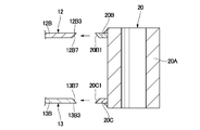
- a groove 20B1 is provided at the rear end of the port portion 20B, and the groove 20B1 is abutted with a front groove 12B7 provided on the front thin side plate 12B.
- the bevel 20B1 has a uniform inclination without a root face by inclining and cutting the rear end edge of the port portion 20B toward the inner surface side. It is formed as a face.
- the left side 20B has a thickness substantially equal to the thickness 12Bt of the front thin side plate 12B. Therefore, as shown in FIG. 15, the outer surface of the front thin side plate 12B and the left collar portion 20B can be obtained by butting the front groove 12B7 of the front thin side plate 12B and the groove 20B1 of the left collar 20B without a gap. It forms the same plane without a level difference with the outer surface of.
- a V-shaped groove 20D having a groove angle ⁇ with no root face and no gap is formed on the inner surface side of the front thin side plate 12B and the left hook portion 20B.
- a groove 20C1 is provided at the rear end of the starboard portion 20C, and the groove 20C1 is abutted with a front groove 13B7 provided on the front thin side plate 13B.
- the groove 20C1 is formed by inclining the rear end edge of the starboard portion 20C toward the inner surface and cutting it out, and is formed as a uniform inclined surface having no root face.
- the right gutter portion 20C has a thickness substantially equal to the thickness 13Bt of the front thin side plate 13B. Therefore, there is no difference in level between the outer surface of the front thin side plate 13B and the outer surface of the right collar portion 20C by abutting the front groove 13B7 of the front thin side plate 13B and the groove 20C1 of the right collar portion 20C without a gap. Form the same plane.
- a V-shaped groove 20E having a groove angle ⁇ with no root face and no gap is formed on the inner surface side of the front thin side plate 13B and the starboard portion 20C.
- bucket connection boss joint portion 13B3 of front thin side plate 13B and right hook portion 20C of bucket connection boss 20 are completely welded. It is joined.
- the cylindrical boss portion 20A of the bucket connecting boss 20 includes a bucket connecting boss joint portion 14B2 of the front thin upper plate 14B constituting the upper plate 14 and a bucket connecting boss joint portion 15B2 of the front thin lower plate 15B constituting the lower plate 15. Are joined by welding.
- Reference numeral 21 denotes a rear link connection boss provided adjacent to the bucket connection boss 20 on the front end side of the left and right side plates 12 and 13.
- the rear link connection boss 21 is formed such that a connection pin (not shown) rotatably connecting between the rear link 7A of the bucket link 7 and the arm 11 is inserted.
- the rear link connection bosses 21 are hollow cylindrical boss portions 21A extending in the left and right directions, and disk-shaped left and right flanges provided on both left and right end sides of the cylindrical boss portions 21A. It is comprised by the part 21B.
- the left flange portion 21B of the rear link connection boss 21 is joined to the rear link connection boss joint hole 12B5 of the front thin side plate 12B, and the right flange portion 21B is joined to the rear link connection boss joint hole 13B5 of the front thin side plate 13B. It is done.
- the reference numeral 22 denotes a pair of arm cylinder brackets provided on the outer surface of the thick rear plate 16, and the arm cylinder brackets 21 are arranged in pairs in the left and right directions.
- Each of the arm cylinder brackets 22 is rotatably connected to a rod end of the arm cylinder 9 via a connection pin (not shown).
- each arm cylinder bracket 22 is formed as a substantially triangular plate using a plate material such as a steel plate, and a pin insertion hole 22A for inserting the above-mentioned connection pin is formed in the central portion thereof. It is set up.
- each arm cylinder bracket 22 is joined to the outer surface of the thick rear plate 16 by welding in a state of maintaining a constant distance in the left and right directions.
- a reference numeral 23 denotes a pair of bucket cylinder brackets provided on the outer surface 14A4 of the rear thick upper plate 14A that constitutes the upper plate 14.
- the bucket cylinder brackets 23 are disposed in pairs in the left and right directions, and the bottom side of the bucket cylinder 10 is rotatably coupled via a coupling pin 10A.
- each bucket cylinder bracket 23 is formed as a plate having a substantially triangular shape using a plate material such as a steel plate material, and a pin insertion hole 23A for inserting the above-mentioned connection pin 10A is provided on the tip side thereof. It is drilled.
- each bucket cylinder bracket 23 is joined by welding to the outer surface 14A4 of the rear thick top plate 14A with a constant distance left and right.
- reference numeral 24 denotes an auxiliary welding member provided on the rear side of the upper plate 14.
- the auxiliary welding member 24 is provided on the outer surface 14A4 of the rear thick upper plate 14A so as to surround the weld between the rear thick upper plate 14A of the upper plate 14 and the bucket cylinder brackets 23.
- the auxiliary welding member 24 is formed as a flat plate having a substantially M shape in a plan view as viewed from above. That is, the auxiliary welding member 24 is generally made of a rectangular flat plate having a width slightly smaller than the width of the rear thick upper plate 14A in the left and right directions.
- the auxiliary welding member 24 has a notch 24B located in the middle between left and right and notched backward from the front end 24A and a pair of grooves 24D extending forward from the rear end 24C. ing.
- the periphery (outer peripheral edge portion) of the auxiliary welding member 24 is fillet-welded to the outer surface 14A4 of the rear thick top plate 14A over the entire periphery.
- the plate thickness 24t of the auxiliary welding member 24 is superimposed on the plate thickness 14At of the rear thick upper plate 14A, and a plate of a portion of the rear thick upper plate 14A where the bucket cylinder bracket 23 is joined. The thickness can be partially increased.
- the front end 24A of the auxiliary welding member 24 is disposed forward of the pin insertion hole 23A of the bucket cylinder bracket 23, and the rear end 24C of the auxiliary welding member 24 is from the upper end 19A of the internal partition 19. It is also located on the back side.
- the auxiliary welding member 24 is disposed so as to extend in the front and rear directions sandwiching the upper end portion 19A of the inner partition wall 19.
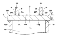
- a bracket-side weld bead 26A constituting a weld bead 26 described later is formed at the junction of the outer surface 14A4 of the rear thick upper plate 14A and the bucket cylinder bracket 23.
- a gap 25 is formed between the groove 24D of the auxiliary welding member 24 and the bucket cylinder bracket 23.
- auxiliary welding member formed between the bracket side weld bead 26A formed between the bucket cylinder bracket 23 and the rear thick upper plate 14A, the groove 24D of the auxiliary welding member 24 and the rear thick upper plate 14A
- the welding bead 26 is formed integrally with the side welding bead 26B.
- the weld bead 26 can fill the gap 25 formed between the groove 24 D of the auxiliary weld member 24 and the bucket cylinder bracket 23.
- the grooves 24D of the auxiliary welding member 24 and the bucket cylinder brackets 23 can be joined by the welding bead 26 which is smoothly continuous.
- the cutout portion 24B provided at the front end portion 24A of the auxiliary welding member 24 a large welding length of the auxiliary welding member 24 to the rear thick upper plate 14A can be secured.
- the arm 11 according to the present embodiment has the above-described configuration, and an example of the procedure for manufacturing the arm 11 will be described with reference to FIG.
- the V-shaped groove 12C is formed by butting the groove 12A6 of the rear thick side plate 12A constituting the left side plate 12 with the rear groove 12B6 of the front thin side plate 12B. Butt welding is performed using a means such as arc welding at the position of the V-shaped groove 12C. In this case, since the V-shaped groove 12C has no root face and no gap, the arc from the welding torch 100 can be supplied over the entire surfaces of the respective grooves 12A6 and 12B6. Thereby, it is possible to perform complete welding in which the rear thick side plate 12A and the front thin side plate 12B are melted into the entire area of the plate thickness.
- the groove angle ⁇ of the V-shaped groove 12C is set in the range of 43 degrees or more and 90 degrees or less, arc heat can be sufficiently supplied to the respective grooves 12A6 and 12B6.
- the inside of the V-shaped groove 12C can be filled with the molten metal without excess or deficiency. Therefore, as shown in FIG. 9, it is possible to form a smoothly continuous weld bead 12F between the rear thick side plate 12A and the front thin side plate 12B. As a result, it is possible to form the left side plate 12 in which the rear thick side plate 12A and the front thin side plate 12B are firmly joined without arranging a backing material or the like on the back side of the V-shaped groove 12C.
- the groove 13A6 of the rear thick side plate 13A constituting the right side plate 13 and the rear groove 13B6 of the front thin side plate 13B are butted to form a V-shaped groove 13C, and the V-shaped groove 13C is formed. Perform butt welding at the position. Thereby, it is possible to form a weld bead 13F that is smoothly continuous between the rear thick side plate 13A and the front thin side plate 13B, and the right side plate 13 in which the rear thick side plate 13A and the front thin side plate 13B are firmly joined is obtained. It can be formed.
- the left and right flange portions 18B of the boom connection boss 18 are joined respectively to the boom connection boss joint groove 12A5 of the left side plate 12 and the boom connection boss joint groove 13A5 of the right side plate 13 by welding. Further, the left and right flange portions 21B of the rear link connection boss 21 are respectively welded to the rear link connection boss joint hole 12B5 of the left side plate 12 and the rear link connection boss joint portion 13B5 of the right side plate 13.
- the front groove 12B7 of the front thin side plate 12B constituting the left side plate 12 and the groove 20B1 of the port portion 20B constituting the bucket connecting boss 20 are butted to each other.
- a groove 20D is formed, and butt welding is performed at the position of the V-shaped groove 20D.
- a weld bead 20F can be formed smoothly and continuously between the front thin side plate 12B and the left hook portion 20B, and the front thin side plate 12B and the left hook portion 20B can be firmly joined.
- a V-shaped groove 20E is formed by butting the front groove 13B7 of the front thin side plate 13B constituting the right side plate 13 and the groove 20C1 of the right collar 20C constituting the bucket connecting boss 20. Butt welding is performed at the position of the groove 20E. Thereby, it is possible to form a smoothly continuous weld bead 20G between the front thin side plate 13B and the right heel portion 20C, and it is possible to firmly bond the front thin side plate 13B and the right heel portion 20C.
- the groove 14A3 of the rear thick upper plate 14A and the groove 14B3 of the front thin upper plate 14B are butted to form a V-shaped groove 14C.
- the upper plate 14 can be formed.
- the V-shaped groove 15C is formed by butting the groove 15A3 of the rear lower thickness plate 15A with the groove 15B3 of the front thin lower plate 15B. Perform butt welding at position 15C. Thereby, it is possible to form a smoothly continuous weld bead 15D between the rear lower thickness plate 15A and the front thin lower plate 15B, and the rear thickness lower plate 15A and the front thin lower plate 15B are firmly joined.
- the lower plate 15 can be formed.
- the upper plate 14 is disposed on the upper side of the left side plate 12 and the right side plate 13, and fillet welding is performed over the entire length between the left side plate 12 and the upper plate 14. Similarly, fillet welding is applied over the entire length between the right side plate 13 and the upper plate 14. Further, the bucket connecting boss joint portion 14B2 of the front thin upper plate 14B constituting the upper plate 14 is joined to the cylindrical boss portion 20A of the bucket connecting boss 20 by welding. Thereby, the upper plate 14 can be joined to the upper end side of the left and right side plates 12 and 13.
- the inner partition wall 19 is prepared, and the upper end portion 19A of the inner partition wall 19 is welded to the vicinity of the front thin upper plate bonding portion 14A2 of the rear thick upper plate 14A constituting the upper plate 14. Further, the lower end 19 B of the inner bulkhead 19 is welded to the cylindrical boss portion 18 A of the boom connection boss 18. Further, the left end 19C of the inner partition 19 is welded to the inner surface of the rear thick side plate 12A of the left side plate 12 and the front thin side plate 12B, and the right end 19C of the inner partition 19 is formed of the rear thick side plate 13A of the right side plate 13 and the front It welds to the inside of thin side board 13B.
- the lower plate 15 is disposed on the lower end side of the left side plate 12 and the right side plate 13, and the fillet welding is performed over the entire length between the left side plate 12 and the lower plate 15. Similarly, a fillet weld is applied between the right side plate 13 and the lower plate 15 over the entire length.
- the boom connection boss joint portion 15A1 of the rear thick lower plate 15A is joined to the cylindrical boss portion 18A of the boom connection boss 18 by welding.
- the bucket connecting boss joint portion 15B2 of the front thin lower plate 15B is joined to the cylindrical boss portion 20A of the bucket connecting boss 20 by welding. Thereby, the lower plate 15 can be joined to the lower end side of the left and right side plates 12 and 13.
- a thick rear plate 16 is prepared.
- a fillet is formed between the rear plate joint portion 12A3 of the rear thick side plate 12A and the thick rear plate 16 Apply welding.
- a fillet is formed between the rear plate joint portion 13A3 of the rear thick side plate 13A and the rear thick plate 16 Apply welding.
- a pair of left and right bucket cylinder brackets 23 is joined to the outer surface of the rear thick upper plate 14A constituting the upper plate 14 by welding.
- the auxiliary welding member 24 is provided on the outer surface 14A4 of the rear thick upper plate 14A so as to surround the weld between the rear thick upper plate 14A and each of the bucket cylinder brackets 23.
- the outer peripheral edge of the auxiliary welding member 24 is fillet welded over the entire circumference to the outer surface 14A4 of the rear thick top plate 14A.
- the plate thickness 24t of the auxiliary welding member 24 can be superimposed on the plate thickness 14At of the rear thick plate 14A, and the bucket cylinder bracket 23 of the rear thick plate 14A is joined.
- the thickness of the portion can be partially increased.
- a bracket-side weld bead 26A is formed at the junction of the outer surface 14A4 of the rear thick top plate 14A and the bucket cylinder bracket 23.
- a gap 25 is formed between the groove 24 D of the auxiliary welding member 24 and the bucket cylinder bracket 23.
- the arm 11 having a closed cross-sectional structure having a square cross section.
- the upper plate 14 is formed by welding the rear thick upper plate 14A having the large thickness 14At and the front thin upper plate 14B having the small thickness 14Bt by welding.
- the bucket cylinder bracket 23 to which the bucket cylinder 10 is connected is joined to the outer surface of the rear thick top plate 14A.
- the rear side of the upper plate 14 requiring high strength is constituted by the rear thick upper plate 14A
- the front side not requiring large strength as compared with the rear side is constituted by the front thin upper plate 14B.
- the lower plate 15 is also formed by welding a rear lower plate 15A having a large plate thickness 15At and a front thin lower plate 15B having a small plate thickness 15Bt by welding.
- the left side plate 12 is also formed by welding a rear thick side plate 12A having a large thickness 12At and a front thin side plate 12B having a small thickness 12Bt by welding
- the right side plate 13 also has a large thickness 13At. It is formed by welding the rear thick side plate 13A and the front thin side plate 13B having a small thickness 13Bt by welding.
- the upper end 12D of this joint is joined to the rear thick upper plate 14A of the upper plate 14
- the lower end 12E of the joint portion is joined to the rear lower plate 15A of the lower plate 14.
- the upper end 13D of this joint is joined to the rear thick upper plate 14A of the upper plate 14.
- the lower end 13E of the joint portion is joined to the rear lower plate 15A of the lower plate 14.
- the strength of the joint between the rear thick side plate 12A and the front thin side plate 12B of the left side plate 12 can be enhanced, and the strength of the joint between the rear thick side plate 13A and the front thin side plate 13B of the right side plate 13 can be enhanced.
- the strength of the entire arm 11 can be increased.
- the inner partition wall 19 is provided between the left and right side plates 12 and 13, the boom connection boss 18, and the upper plate 14.
- two closed spaces can be formed in the arm 11 by the internal partition wall 19, and the rigidity of the entire arm 11 can be enhanced.
- the thick rear plate 16 is used as the rear thick side plates 12A and 13A of the left and right side plates 12 and 13 and the rear thick plate 14A of the upper plate 14 and the rear thick lower plate of the lower plate 15. It is formed using a plate having a thickness equal to or greater than 15A. Thereby, the strength of the rear end of the arm 11 on which the arm cylinder bracket 22 is provided can be further enhanced.
- the V-shaped groove 12C is formed between the groove 12A6 provided on the rear thick side plate 12A of the left side plate 12 and the rear side groove 12B6 provided on the front thin side plate 12B.
- the bonding strength between the rear thick side plate 12A and the front thin side plate 12B can be enhanced.
- the rear thickness is obtained.
- the bonding strength between the side plate 13A and the front thin side plate 13B can be increased.
- a V-shaped groove 20D is formed between the front groove 12B7 of the front thin side plate 12B and the groove 20B1 of the port 20B of the bucket connecting boss 20, and the front groove 13B7 of the front thin side plate 13B;
- a V-shaped groove 20E is formed between the bucket connecting boss 20 and the groove 20C1 of the right heel portion 20C.
- the rear thick upper plate 14A is formed. And the bonding strength between the front thin upper plate 14B and the front thin upper plate 14B.
- the V-shaped groove 15C is formed between the groove 15A3 provided on the rear thick lower plate 15A of the lower plate 15 and the groove 15B3 provided on the front thin lower plate 15B.
- the bonding strength between the lower plate 15A and the front thin lower plate 15B can be increased.
- the fillet welding is performed over the entire circumference between the outer peripheral edge of the auxiliary welding member 24 and the rear thick upper plate 14A.
- the thickness of the portion of the rear thickness upper plate 14A where the bucket cylinder bracket 23 is joined can be increased by the thickness of the auxiliary welding member 24.
- each groove 24D of the auxiliary welding member 24 and each bucket cylinder bracket 23 is , Can be joined by a smoothly continuous weld bead 26.
- the bonding strength of each bucket cylinder bracket 23 to the rear thick upper plate 14A can be enhanced.
- auxiliary welding member 27 having the notch 24B and the left and right grooves 24D is illustrated.
- the present invention is not limited to this.
- a total of two auxiliary welding members 27 are provided to the left and right bucket cylinder brackets 23, one each. It is also good.
- the auxiliary welding member 27 is formed of a rectangular flat plate extending in the front and rear directions, with the bucket cylinder bracket 23 inserted in one groove 27A extending in the front and rear directions, the outer peripheral edge of the auxiliary welding member 27 is all around Fillet-welded to the outer surface 14A4 of the rear thick top plate 14A.
- the boom connection boss 18, the bucket connection boss 20, and the rear link connection boss 21 are joined to the left and right side plates 12 and 13 as an example of the procedure for assembling the arm 11. , 13 to the upper plate 14.
- the assembly procedure of the arm 11 according to the present invention is not limited to the above-described embodiment, and the procedure of assembling the arm 11 can be changed as appropriate.
- the backing material 17 is fixed to the rear thick side plates 12A and 13A constituting the left and right side plates 12 and 13, and the rear thick side plates 12A and 13A and the rear thick side plates 12A and 13A are utilized.
- a configuration in which fillet welding is performed between the thick rear plate 16 is illustrated.
- the present invention is not limited to this, and a configuration may be adopted in which fillet welding is performed between the rear thick side plates 12A and 13A and the thick rear plate 16 without using the backing material 17.
- the crawler type hydraulic shovel 1 is described as an example of the construction machine.
- the present invention is not limited to this, and can be widely applied to, for example, an arm for another construction machine such as an arm used for a wheeled hydraulic excavator.
Landscapes
- Engineering & Computer Science (AREA)
- Mechanical Engineering (AREA)
- Mining & Mineral Resources (AREA)
- Civil Engineering (AREA)
- General Engineering & Computer Science (AREA)
- Structural Engineering (AREA)
- Shovels (AREA)
- Body Structure For Vehicles (AREA)
Abstract
Description






10 バケットシリンダ
10A 連結ピン
11 アーム
12 左側板
12A,13A 後厚側板
12A6,13A6,14A3,14B3,15A3,15B3,20B1,20C1 開先
12B,13B 前薄側板
12B6,13B6 後側開先(開先)
12B7,13B7 前側開先(開先)
12C,13C,14C,15C,20D,20E V形開先
13 右側板
14 上板
14A 後厚上板
14A4 外面
14B 前薄上板
15 下板
15A 後厚下板
15B 前薄下板
16 厚後板
18 ブーム連結ボス
19 内部隔壁
19A 上端
20 バケット連結ボス
20A 円筒状ボス部
20B 左鍔部
20C 右鍔部
23 バケットシリンダブラケット
24,27 補助溶接部材
24A 前端
24B 切欠部
24C 後端
25 隙間
26 溶接ビード
26A ブラケット側溶接ビード
26B 補助溶接部材側溶接ビード
Claims (15)
- 左,右の側板(12,13)と、該左,右の側板(12,13)の上端側に溶接により接合された上板(14)と、前記左,右の側板(12,13)の下端側に溶接により接合された下板(15)と、前記左,右の側板(12,13)の後端側と前記上板(14)の後端側とに溶接により接合された後板(16)とにより横断面が四角形をなす箱型構造体として形成され、
前記左,右の側板(12,13)の後部下側に位置して、該左,右の側板(12,13)と前記下板(15)の後端と前記後板(16)の前端とに溶接により接合されたブーム連結ボス(18)を設け、
前記左,右の側板(12,13)、上板(14)および下板(15)の前端に溶接により接合されたバケット連結ボス(20)を設け、
前記上板(14)の外面に溶接により接合された左,右方向で一対のバケットシリンダブラケット(23)とを設けてなる建設機械用アームにおいて、
前記上板(14)は、後側に位置して板厚が厚い板材からなる後厚上板(14A)と、該後厚上板(14A)の前側に位置して板厚が薄い板材からなる前薄上板(14B)との2部材を接合することにより形成し、
前記バケットシリンダブラケット(23)は、前記後厚上板(14A)の外面に接合する構成としたことを特徴とする建設機械用アーム。 - 左,右の側板(12,13)と、該左,右の側板(12,13)の上端側に溶接により接合された上板(14)と、前記左,右の側板(12,13)の下端側に溶接により接合された下板(15)と、前記左,右の側板(12,13)の後端側と前記上板(14)の後端側とに溶接により接合された後板(16)とにより横断面が四角形をなす箱型構造体として形成され、
前記左,右の側板(12,13)の後部下側に位置して、該左,右の側板(12,13)と前記下板(15)の後端と前記後板(16)の前端とに溶接により接合されたブーム連結ボス(18)を設け、
前記左,右の側板(12,13)、上板(14)および下板(15)の前端に溶接により接合されたバケット連結ボス(20)を設け、
前記上板(14)の外面に溶接により接合された左,右方向で一対のバケットシリンダブラケット(23)とを設けてなる建設機械用アームにおいて、
前記下板(15)は、後側に位置して板厚が厚い板材からなる後厚下板(15A)と、該後厚下板(15A)の前側に位置して板厚が薄い板材からなる前薄下板(15B)との2部材を接合することにより形成し、
前記ブーム連結ボス(18)は、前記後厚下板(15A)の後端に接合する構成としたことを特徴とする建設機械用アーム。 - 左,右の側板(12,13)と、該左,右の側板(12,13)の上端側に溶接により接合された上板(14)と、前記左,右の側板(12,13)の下端側に溶接により接合された下板(15)と、前記左,右の側板(12,13)の後端側と前記上板(14)の後端側とに溶接により接合された後板(16)とにより横断面が四角形をなす箱型構造体として形成され、
前記左,右の側板(12,13)の後部下側に位置して、該左,右の側板(12,13)と前記下板(15)の後端と前記後板(16)の前端とに溶接により接合されたブーム連結ボス(18)を設け、
前記左,右の側板(12,13)、上板(14)および下板(15)の前端に溶接により接合されたバケット連結ボス(20)を設け、
前記上板(14)の外面に溶接により接合された左,右方向で一対のバケットシリンダブラケット(23)とを設けてなる建設機械用アームにおいて、
前記上板(14)は、後側に位置して板厚が厚い板材からなる後厚上板(14A)と、該後厚上板(14A)の前側に位置して板厚が薄い板材からなる前薄上板(14B)との2部材を接合することにより形成し、
前記下板(15)は、後側に位置して板厚が厚い板材からなる後厚下板(15A)と、該後厚下板(15A)の前側に位置して板厚が薄い板材からなる前薄下板(15B)との2部材を接合することにより形成し、
前記バケットシリンダブラケット(23)は、前記後厚上板(14A)の外面に接合する構成とし、
前記ブーム連結ボス(18)は、前記後厚下板(15A)の後端に接合する構成としたことを特徴とする建設機械用アーム。 - 左,右の側板(12,13)と、該左,右の側板(12,13)の上端側に溶接により接合された上板(14)と、前記左,右の側板(12,13)の下端側に溶接により接合された下板(15)と、前記左,右の側板(12,13)の後端側と前記上板(14)の後端側とに溶接により接合された後板(16)とにより横断面が四角形をなす箱型構造体として形成され、
前記左,右の側板(12,13)の後部下側に位置して、該左,右の側板(12,13)と前記下板(15)の後端と前記後板(16)の前端とに溶接により接合されたブーム連結ボス(18)を設け、
前記左,右の側板(12,13)、上板(14)および下板(15)の前端に溶接により接合されたバケット連結ボス(20)を設け、
前記上板(14)の外面に溶接により接合された左,右方向で一対のバケットシリンダブラケット(23)とを設けてなる建設機械用アームにおいて、
前記上板(14)は、後側に位置して板厚が厚い板材からなる後厚上板(14A)と、該後厚上板(14A)の前側に位置して板厚が薄い板材からなる前薄上板(14B)との2部材を接合することにより形成し、
前記下板(15)は、後側に位置して板厚が厚い板材からなる後厚下板(15A)と、該後厚下板(15A)の前側に位置して板厚が薄い板材からなる前薄下板(15B)との2部材を接合することにより形成し、
前記左,右の側板(12,13)は、後側に位置して板厚が厚い板材からなる後厚側板(12A,13A)と、該後厚側板(12A,13A)の前側に位置して板厚が薄い板材からなる前薄側板(12B,13B)との2部材を接合することにより形成し、
前記バケットシリンダブラケット(23)は、前記後厚上板(14A)の外面に接合する構成とし、
前記ブーム連結ボス(18)は、前記後厚下板(15A)の後端に接合する構成とし、
前記後厚側板(12A,13A)と前記前薄側板(12B,13B)との接合部は、その上端(12D,13D)を前記後厚上板(14A)に接合し、下端(12E,13E)を前記後厚下板(15A)に接合する構成としたことを特徴とする建設機械用アーム。 - 前記後厚上板(14A)の内面側と前記ブーム連結ボス(18)との間には、補強用の内部隔壁(19)を設ける構成としてなる請求項1,3または4に記載の建設機械用アーム。
- 前記後板(16)は、前記後厚上板(14A)および前記後厚側板(12A,13A)と同等以上の板厚を有する板材を用いた厚後板(16)として形成し、
該厚後板(16)は、前記左,右の後厚側板(12A,13A)の後端と前記後厚上板(14A)の後端とに接合すると共に、前記厚後板(16)の前端を前記ブーム連結ボス(18)に接合する構成としてなる請求項4に記載の建設機械用アーム。 - 前記後厚側板(12A,13A)の前端と前記前薄側板(12B,13B)の後端とには、ルートフェイスなく切欠くことにより上,下方向に延びる開先(12A6,13A6,12B6,13B6)をそれぞれ設け、
前記後厚側板(12A,13A)の開先(12A6,13A6)と前記前薄側板(12B,13B)の開先(12B6,13B6)とを突合わせることにより、ルートフェイスがなくかつギャップがないV形開先(12C,13C)を形成し、
該V形開先(12C,13C)の位置で前記後厚側板(12A,13A)と前記前薄側板(12B,13B)との間に溶接を施すことにより溶接ビード(12F,13F)を形成する構成としてなる請求項4に記載の建設機械用アーム。 - 前記バケット連結ボス(20)には、円筒状ボス部(20A)の左,右両側に位置して前記左,右の側板(12,13)に向けて延びる鍔部(20B,20C)を設け、
前記左,右の側板(12,13)の前端には、ルートフェイスなく切欠くことにより上,下方向に延びる開先(12B7,13B7)をそれぞれ設け、
前記バケット連結ボス(20)の左,右の鍔部(20B,20C)の後端には、ルートフェイスなく切欠くことにより上,下方向に延びる開先(20B1,20C1)をそれぞれ設け、
前記左,右の側板(12,13)の開先(12B7,13B7)と前記左,右の鍔部(20B,20C)の開先(20B1,20C1)とを突合わせることにより、ルートフェイスがなくかつギャップがないV形開先(20D,20E)を形成し、
該V形開先(20D,20E)の位置で前記左,右の側板(12,13)と前記左,右の鍔部(20B,20C)との間に溶接を施すことにより溶接ビード(20F,20G)を形成する構成としてなる請求項1,2,3または4に記載の建設機械用アーム。 - 前記後厚上板(14A)の前端と前記前薄上板(14B)の後端とには、ルートフェイスなく切欠くことにより左,右方向に延びる開先(14A3,14B3)をそれぞれ設け、
前記後厚上板(14A)の開先(14A3)と前記前薄上板(14B)の開先(14B3)とを突合わせることにより、ルートフェイスがなくかつギャップがないV形開先(14C)を形成し、
該V形開先(14C)の位置で前記後厚上板(14A)と前記前薄上板(14B)との間に溶接を施すことにより溶接ビード(14D)を形成する構成としてなる請求項1,3または4に記載の建設機械用アーム。 - 前記後厚下板(15A)の前端と前記前薄下板(15B)の後端とには、ルートフェイスなく切欠くことにより左,右方向に延びる開先(15A3,15B3)をそれぞれ設け、
前記後厚下板(15A)の開先(15A3)と前記前薄下板(15B)の開先(15B3)とを突合わせることにより、ルートフェイスがなく、かつギャップがないV形開先(15C)を形成し、
該V形開先(15C)の位置で前記後厚下板(15A)と前記前薄下板(15B)との間に溶接を施すことにより溶接ビード(15D)を形成する構成としてなる請求項2,3または4に記載の建設機械用アーム。 - 前記V形開先(12C,13C,14C,15C,20D,20E)の開先角度は、43度以上90度以下の範囲に設定する構成としてなる請求項7,8,9または10に記載の建設機械用アーム。
- 前記上板(14)の後部側の外面(14A4)には、前記左,右方向で一対のバケットシリンダブラケット(23)と前記上板(14)との溶接部を囲むように平板状の補助溶接部材(24)を設け、
該補助溶接部材(24)の周囲に隅肉溶接を施すことにより溶接ビード(26)を形成する構成としてなる請求項1,2,3または4に記載の建設機械用アーム。 - 前記ブーム連結ボス(18)と、前記上板(14)の内面側であって前記バケットシリンダブラケット(23)に設けられた連結ピン(10A)の位置よりも前側の位置との間に、補強用の内部隔壁(19)を設け、
前記補助溶接部材(24)の後端(24C)は、前記内部隔壁(19)の上端位置よりも後側まで延在させる構成としてなる請求項12に記載の建設機械用アーム。 - 前記上板(14)の外面(14A)において前記バケットシリンダブラケット(23)と前記補助溶接部材(24)との間に生じる隙間(25)は、前記バケットシリンダブラケット(23)の溶接ビード(26A)と、前記補助溶接部材(24)の溶接ビード(26B)とにより埋込む構成としてなる請求項12に記載の建設機械用アーム。
- 前記補助溶接部材(24)は、平面視でM字形に形成し、
該M字形補助溶接部材(24)の前部側には、後方に向けて凹形状に切欠いた切欠部(24B)を設ける構成としてなる請求項12に記載の建設機械用アーム。
Priority Applications (4)
| Application Number | Priority Date | Filing Date | Title |
|---|---|---|---|
| US14/003,341 US9255378B2 (en) | 2011-05-19 | 2012-05-16 | Arm for construction machine |
| KR1020137030711A KR101821273B1 (ko) | 2011-05-19 | 2012-05-16 | 건설 기계용 아암 |
| EP12785926.2A EP2711466B1 (en) | 2011-05-19 | 2012-05-16 | Arm for construction machinery |
| CN201280024343.0A CN103547739B (zh) | 2011-05-19 | 2012-05-16 | 工程机械用悬臂 |
Applications Claiming Priority (6)
| Application Number | Priority Date | Filing Date | Title |
|---|---|---|---|
| JP2011112825A JP5595974B2 (ja) | 2011-05-19 | 2011-05-19 | 建設機械用アーム |
| JP2011112820A JP5562903B2 (ja) | 2011-05-19 | 2011-05-19 | 建設機械用アーム |
| JP2011-112821 | 2011-05-19 | ||
| JP2011-112820 | 2011-05-19 | ||
| JP2011112821A JP5511732B2 (ja) | 2011-05-19 | 2011-05-19 | 建設機械用アーム |
| JP2011-112825 | 2011-05-19 |
Publications (1)
| Publication Number | Publication Date |
|---|---|
| WO2012157675A1 true WO2012157675A1 (ja) | 2012-11-22 |
Family
ID=47176992
Family Applications (1)
| Application Number | Title | Priority Date | Filing Date |
|---|---|---|---|
| PCT/JP2012/062514 Ceased WO2012157675A1 (ja) | 2011-05-19 | 2012-05-16 | 建設機械用アーム |
Country Status (5)
| Country | Link |
|---|---|
| US (1) | US9255378B2 (ja) |
| EP (1) | EP2711466B1 (ja) |
| KR (1) | KR101821273B1 (ja) |
| CN (1) | CN103547739B (ja) |
| WO (1) | WO2012157675A1 (ja) |
Cited By (2)
| Publication number | Priority date | Publication date | Assignee | Title |
|---|---|---|---|---|
| GB2518000A (en) * | 2013-09-10 | 2015-03-11 | Jc Bamford Excavators Ltd | Welded Component and method of fabrication |
| US10370817B2 (en) * | 2014-06-05 | 2019-08-06 | Hitachi Construction Machinery Co., Ltd. | Boom for construction machine |
Families Citing this family (9)
| Publication number | Priority date | Publication date | Assignee | Title |
|---|---|---|---|---|
| JP5937626B2 (ja) * | 2012-02-16 | 2016-06-22 | 日立建機株式会社 | 建設機械用アーム |
| JP6178284B2 (ja) * | 2014-06-13 | 2017-08-09 | 株式会社クボタ | 作業機の作業要素 |
| KR101674736B1 (ko) * | 2014-10-02 | 2016-11-10 | 한양대학교 산학협력단 | 리튬 공기 이차 전지, 및 그 제조 방법 |
| JP6507990B2 (ja) | 2014-11-06 | 2019-05-08 | コベルコ建機株式会社 | 建設機械のアーム及びその製造方法 |
| JP6433782B2 (ja) * | 2014-12-24 | 2018-12-05 | 日立建機株式会社 | 建設機械用アームおよび建設機械用アームに用いるバケット連結ボスの交換方法 |
| GB201506783D0 (en) * | 2015-04-21 | 2015-06-03 | Bamford Excavators Ltd | A method of mounting an attachment |
| DE102016112748A1 (de) | 2016-07-12 | 2018-01-18 | Schwing Gmbh | Großmanipulator mit gewichtoptimiertem Knickmast |
| JP6829674B2 (ja) * | 2017-09-25 | 2021-02-10 | 日立建機株式会社 | 作業機械の作業腕 |
| CN115218739B (zh) * | 2022-06-29 | 2023-10-10 | 湖南金石智造科技有限公司 | 一种智能对孔机械手及其工作方法 |
Citations (5)
| Publication number | Priority date | Publication date | Assignee | Title |
|---|---|---|---|---|
| JPS6127199A (ja) * | 1984-07-17 | 1986-02-06 | Nippon Steel Corp | 片面溶接用裏当材 |
| JP2003261956A (ja) | 2002-01-04 | 2003-09-19 | Komatsu Ltd | 作業機の長尺構造部材 |
| JP2005029984A (ja) * | 2003-07-08 | 2005-02-03 | Hitachi Constr Mach Co Ltd | 建設機械用作業腕及びその製造方法 |
| JP2005213819A (ja) * | 2004-01-28 | 2005-08-11 | Hitachi Constr Mach Co Ltd | 建設機械用作業腕 |
| JP2006026682A (ja) * | 2004-07-15 | 2006-02-02 | Nippon Steel Corp | 溶接部疲労強度に優れる建設機械のブーム・アーム部材およびその疲労強度向上方法 |
Family Cites Families (12)
| Publication number | Priority date | Publication date | Assignee | Title |
|---|---|---|---|---|
| US3902295A (en) | 1974-05-28 | 1975-09-02 | Caterpillar Tractor Co | Boom construction and method for making same |
| JPH1110383A (ja) * | 1997-06-17 | 1999-01-19 | Komatsu Ltd | 溶接部材及びその溶接部成形方法 |
| WO1999004104A1 (en) * | 1997-07-15 | 1999-01-28 | Komatsu Ltd. | Structure for working unit for bucket excavators and method for manufacturing the same |
| JP2000248576A (ja) * | 1999-03-03 | 2000-09-12 | Shin Caterpillar Mitsubishi Ltd | 作業機械の作業腕構造 |
| JP2003034946A (ja) * | 2001-07-23 | 2003-02-07 | Kubota Corp | 掘削作業機のアーム補強構造 |
| US7165929B2 (en) | 2001-12-20 | 2007-01-23 | Caterpillar Inc | Load bearing member arrangement and method |
| JP2004270269A (ja) * | 2003-03-07 | 2004-09-30 | Hitachi Constr Mach Co Ltd | 建設機械の作業腕駆動用シリンダのブラケット |
| CN1530496B (zh) * | 2003-03-10 | 2010-04-21 | 株式会社小松制作所 | 建筑机械的履带构架 |
| WO2005001211A1 (ja) * | 2003-06-30 | 2005-01-06 | Hitachi Construction Machinery Co., Ltd. | 建設機械用作業腕及びその製造方法 |
| JP4948080B2 (ja) * | 2006-08-11 | 2012-06-06 | 株式会社クボタ | ブーム |
| US8610031B2 (en) * | 2009-11-11 | 2013-12-17 | Lincoln Global, Inc. | Method of arc welding root pass |
| CN201574412U (zh) * | 2009-12-31 | 2010-09-08 | 斗山工程机械(中国)有限公司 | 一种挖掘机动臂加强结构及挖掘机 |
-
2012
- 2012-05-16 US US14/003,341 patent/US9255378B2/en active Active
- 2012-05-16 WO PCT/JP2012/062514 patent/WO2012157675A1/ja not_active Ceased
- 2012-05-16 KR KR1020137030711A patent/KR101821273B1/ko not_active Expired - Fee Related
- 2012-05-16 CN CN201280024343.0A patent/CN103547739B/zh active Active
- 2012-05-16 EP EP12785926.2A patent/EP2711466B1/en active Active
Patent Citations (5)
| Publication number | Priority date | Publication date | Assignee | Title |
|---|---|---|---|---|
| JPS6127199A (ja) * | 1984-07-17 | 1986-02-06 | Nippon Steel Corp | 片面溶接用裏当材 |
| JP2003261956A (ja) | 2002-01-04 | 2003-09-19 | Komatsu Ltd | 作業機の長尺構造部材 |
| JP2005029984A (ja) * | 2003-07-08 | 2005-02-03 | Hitachi Constr Mach Co Ltd | 建設機械用作業腕及びその製造方法 |
| JP2005213819A (ja) * | 2004-01-28 | 2005-08-11 | Hitachi Constr Mach Co Ltd | 建設機械用作業腕 |
| JP2006026682A (ja) * | 2004-07-15 | 2006-02-02 | Nippon Steel Corp | 溶接部疲労強度に優れる建設機械のブーム・アーム部材およびその疲労強度向上方法 |
Cited By (4)
| Publication number | Priority date | Publication date | Assignee | Title |
|---|---|---|---|---|
| GB2518000A (en) * | 2013-09-10 | 2015-03-11 | Jc Bamford Excavators Ltd | Welded Component and method of fabrication |
| GB2518000B (en) * | 2013-09-10 | 2017-05-31 | Jc Bamford Excavators Ltd | Welded component and method of fabrication |
| US9856624B2 (en) | 2013-09-10 | 2018-01-02 | J.C. Bamford Excavators Limited | Welded component and method of fabrication |
| US10370817B2 (en) * | 2014-06-05 | 2019-08-06 | Hitachi Construction Machinery Co., Ltd. | Boom for construction machine |
Also Published As
| Publication number | Publication date |
|---|---|
| EP2711466A4 (en) | 2015-05-20 |
| EP2711466A1 (en) | 2014-03-26 |
| KR20140027290A (ko) | 2014-03-06 |
| US9255378B2 (en) | 2016-02-09 |
| US20140010624A1 (en) | 2014-01-09 |
| KR101821273B1 (ko) | 2018-01-23 |
| EP2711466B1 (en) | 2018-02-21 |
| CN103547739B (zh) | 2016-06-08 |
| CN103547739A (zh) | 2014-01-29 |
Similar Documents
| Publication | Publication Date | Title |
|---|---|---|
| JP5937626B2 (ja) | 建設機械用アーム | |
| EP2711466B1 (en) | Arm for construction machinery | |
| US7670099B2 (en) | Working arm for construction machine and method of producing the same | |
| EP2711467B1 (en) | Arm for construction machinery | |
| JP5511732B2 (ja) | 建設機械用アーム | |
| WO2010007870A1 (ja) | 建設機械のキャブ | |
| US7997619B2 (en) | Track frame for work machine | |
| JP4938637B2 (ja) | 平板材間の溶接継手および箱型構造体間の溶接継手 | |
| JP5562903B2 (ja) | 建設機械用アーム | |
| JP2013147794A (ja) | 建設機械用アーム | |
| JP2003213727A (ja) | 建設機械の旋回フレーム | |
| WO2012157673A1 (ja) | 建設機械用アーム | |
| JP5595974B2 (ja) | 建設機械用アーム | |
| JP2008050807A (ja) | 溶接構造体 | |
| JP6433782B2 (ja) | 建設機械用アームおよび建設機械用アームに用いるバケット連結ボスの交換方法 | |
| JP2012021336A (ja) | 建設機械のアーム及びその製作方法 | |
| JP4823005B2 (ja) | トラックフレーム | |
| JP2017214715A (ja) | 建設機械用作業腕 |
Legal Events
| Date | Code | Title | Description |
|---|---|---|---|
| 121 | Ep: the epo has been informed by wipo that ep was designated in this application |
Ref document number: 12785926 Country of ref document: EP Kind code of ref document: A1 |
|
| WWE | Wipo information: entry into national phase |
Ref document number: 14003341 Country of ref document: US |
|
| WWE | Wipo information: entry into national phase |
Ref document number: 2012785926 Country of ref document: EP |
|
| ENP | Entry into the national phase |
Ref document number: 20137030711 Country of ref document: KR Kind code of ref document: A |
|
| NENP | Non-entry into the national phase |
Ref country code: DE |