WO2012157685A1 - Dispositif de mesure optique pour réacteur et procédé associé - Google Patents
Dispositif de mesure optique pour réacteur et procédé associé Download PDFInfo
- Publication number
- WO2012157685A1 WO2012157685A1 PCT/JP2012/062550 JP2012062550W WO2012157685A1 WO 2012157685 A1 WO2012157685 A1 WO 2012157685A1 JP 2012062550 W JP2012062550 W JP 2012062550W WO 2012157685 A1 WO2012157685 A1 WO 2012157685A1
- Authority
- WO
- WIPO (PCT)
- Prior art keywords
- reaction
- reaction vessel
- light guide
- measurement
- container
- Prior art date
- Legal status (The legal status is an assumption and is not a legal conclusion. Google has not performed a legal analysis and makes no representation as to the accuracy of the status listed.)
- Ceased
Links
- IFTRQJLVEBNKJK-UHFFFAOYSA-N CCC1CCCC1 Chemical compound CCC1CCCC1 IFTRQJLVEBNKJK-UHFFFAOYSA-N 0.000 description 1
Images




Classifications
-
- G—PHYSICS
- G01—MEASURING; TESTING
- G01N—INVESTIGATING OR ANALYSING MATERIALS BY DETERMINING THEIR CHEMICAL OR PHYSICAL PROPERTIES
- G01N21/00—Investigating or analysing materials by the use of optical means, i.e. using sub-millimetre waves, infrared, visible or ultraviolet light
- G01N21/62—Systems in which the material investigated is excited whereby it emits light or causes a change in wavelength of the incident light
- G01N21/63—Systems in which the material investigated is excited whereby it emits light or causes a change in wavelength of the incident light optically excited
- G01N21/64—Fluorescence; Phosphorescence
- G01N21/6428—Measuring fluorescence of fluorescent products of reactions or of fluorochrome labelled reactive substances, e.g. measuring quenching effects, using measuring "optrodes"
-
- G—PHYSICS
- G01—MEASURING; TESTING
- G01N—INVESTIGATING OR ANALYSING MATERIALS BY DETERMINING THEIR CHEMICAL OR PHYSICAL PROPERTIES
- G01N21/00—Investigating or analysing materials by the use of optical means, i.e. using sub-millimetre waves, infrared, visible or ultraviolet light
- G01N21/75—Systems in which material is subjected to a chemical reaction, the progress or the result of the reaction being investigated
- G01N21/77—Systems in which material is subjected to a chemical reaction, the progress or the result of the reaction being investigated by observing the effect on a chemical indicator
- G01N21/78—Systems in which material is subjected to a chemical reaction, the progress or the result of the reaction being investigated by observing the effect on a chemical indicator producing a change of colour
-
- C—CHEMISTRY; METALLURGY
- C12—BIOCHEMISTRY; BEER; SPIRITS; WINE; VINEGAR; MICROBIOLOGY; ENZYMOLOGY; MUTATION OR GENETIC ENGINEERING
- C12Q—MEASURING OR TESTING PROCESSES INVOLVING ENZYMES, NUCLEIC ACIDS OR MICROORGANISMS; COMPOSITIONS OR TEST PAPERS THEREFOR; PROCESSES OF PREPARING SUCH COMPOSITIONS; CONDITION-RESPONSIVE CONTROL IN MICROBIOLOGICAL OR ENZYMOLOGICAL PROCESSES
- C12Q1/00—Measuring or testing processes involving enzymes, nucleic acids or microorganisms; Compositions therefor; Processes of preparing such compositions
- C12Q1/68—Measuring or testing processes involving enzymes, nucleic acids or microorganisms; Compositions therefor; Processes of preparing such compositions involving nucleic acids
- C12Q1/6844—Nucleic acid amplification reactions
- C12Q1/686—Polymerase chain reaction [PCR]
-
- G—PHYSICS
- G01—MEASURING; TESTING
- G01N—INVESTIGATING OR ANALYSING MATERIALS BY DETERMINING THEIR CHEMICAL OR PHYSICAL PROPERTIES
- G01N21/00—Investigating or analysing materials by the use of optical means, i.e. using sub-millimetre waves, infrared, visible or ultraviolet light
- G01N21/17—Systems in which incident light is modified in accordance with the properties of the material investigated
- G01N21/25—Colour; Spectral properties, i.e. comparison of effect of material on the light at two or more different wavelengths or wavelength bands
- G01N21/251—Colorimeters; Construction thereof
- G01N21/253—Colorimeters; Construction thereof for batch operation, i.e. multisample apparatus
-
- G—PHYSICS
- G01—MEASURING; TESTING
- G01N—INVESTIGATING OR ANALYSING MATERIALS BY DETERMINING THEIR CHEMICAL OR PHYSICAL PROPERTIES
- G01N21/00—Investigating or analysing materials by the use of optical means, i.e. using sub-millimetre waves, infrared, visible or ultraviolet light
- G01N21/62—Systems in which the material investigated is excited whereby it emits light or causes a change in wavelength of the incident light
- G01N21/63—Systems in which the material investigated is excited whereby it emits light or causes a change in wavelength of the incident light optically excited
- G01N21/64—Fluorescence; Phosphorescence
-
- G—PHYSICS
- G01—MEASURING; TESTING
- G01N—INVESTIGATING OR ANALYSING MATERIALS BY DETERMINING THEIR CHEMICAL OR PHYSICAL PROPERTIES
- G01N21/00—Investigating or analysing materials by the use of optical means, i.e. using sub-millimetre waves, infrared, visible or ultraviolet light
- G01N21/62—Systems in which the material investigated is excited whereby it emits light or causes a change in wavelength of the incident light
- G01N21/63—Systems in which the material investigated is excited whereby it emits light or causes a change in wavelength of the incident light optically excited
- G01N21/64—Fluorescence; Phosphorescence
- G01N21/645—Specially adapted constructive features of fluorimeters
- G01N21/6452—Individual samples arranged in a regular 2D-array, e.g. multiwell plates
-
- G—PHYSICS
- G01—MEASURING; TESTING
- G01N—INVESTIGATING OR ANALYSING MATERIALS BY DETERMINING THEIR CHEMICAL OR PHYSICAL PROPERTIES
- G01N21/00—Investigating or analysing materials by the use of optical means, i.e. using sub-millimetre waves, infrared, visible or ultraviolet light
- G01N21/62—Systems in which the material investigated is excited whereby it emits light or causes a change in wavelength of the incident light
- G01N21/63—Systems in which the material investigated is excited whereby it emits light or causes a change in wavelength of the incident light optically excited
- G01N21/64—Fluorescence; Phosphorescence
- G01N21/645—Specially adapted constructive features of fluorimeters
- G01N21/6452—Individual samples arranged in a regular 2D-array, e.g. multiwell plates
- G01N21/6454—Individual samples arranged in a regular 2D-array, e.g. multiwell plates using an integrated detector array
-
- G—PHYSICS
- G01—MEASURING; TESTING
- G01N—INVESTIGATING OR ANALYSING MATERIALS BY DETERMINING THEIR CHEMICAL OR PHYSICAL PROPERTIES
- G01N21/00—Investigating or analysing materials by the use of optical means, i.e. using sub-millimetre waves, infrared, visible or ultraviolet light
- G01N21/75—Systems in which material is subjected to a chemical reaction, the progress or the result of the reaction being investigated
- G01N21/76—Chemiluminescence; Bioluminescence
-
- G—PHYSICS
- G01—MEASURING; TESTING
- G01N—INVESTIGATING OR ANALYSING MATERIALS BY DETERMINING THEIR CHEMICAL OR PHYSICAL PROPERTIES
- G01N35/00—Automatic analysis not limited to methods or materials provided for in any single one of groups G01N1/00 - G01N33/00; Handling materials therefor
-
- G—PHYSICS
- G01—MEASURING; TESTING
- G01N—INVESTIGATING OR ANALYSING MATERIALS BY DETERMINING THEIR CHEMICAL OR PHYSICAL PROPERTIES
- G01N35/00—Automatic analysis not limited to methods or materials provided for in any single one of groups G01N1/00 - G01N33/00; Handling materials therefor
- G01N35/02—Automatic analysis not limited to methods or materials provided for in any single one of groups G01N1/00 - G01N33/00; Handling materials therefor using a plurality of sample containers moved by a conveyor system past one or more treatment or analysis stations
-
- G—PHYSICS
- G01—MEASURING; TESTING
- G01N—INVESTIGATING OR ANALYSING MATERIALS BY DETERMINING THEIR CHEMICAL OR PHYSICAL PROPERTIES
- G01N35/00—Automatic analysis not limited to methods or materials provided for in any single one of groups G01N1/00 - G01N33/00; Handling materials therefor
- G01N35/02—Automatic analysis not limited to methods or materials provided for in any single one of groups G01N1/00 - G01N33/00; Handling materials therefor using a plurality of sample containers moved by a conveyor system past one or more treatment or analysis stations
- G01N35/04—Details of the conveyor system
-
- G—PHYSICS
- G02—OPTICS
- G02B—OPTICAL ELEMENTS, SYSTEMS OR APPARATUS
- G02B21/00—Microscopes
- G02B21/0004—Microscopes specially adapted for specific applications
- G02B21/002—Scanning microscopes
-
- G—PHYSICS
- G01—MEASURING; TESTING
- G01N—INVESTIGATING OR ANALYSING MATERIALS BY DETERMINING THEIR CHEMICAL OR PHYSICAL PROPERTIES
- G01N21/00—Investigating or analysing materials by the use of optical means, i.e. using sub-millimetre waves, infrared, visible or ultraviolet light
- G01N21/62—Systems in which the material investigated is excited whereby it emits light or causes a change in wavelength of the incident light
- G01N21/63—Systems in which the material investigated is excited whereby it emits light or causes a change in wavelength of the incident light optically excited
- G01N21/64—Fluorescence; Phosphorescence
- G01N21/645—Specially adapted constructive features of fluorimeters
- G01N2021/6484—Optical fibres
-
- G—PHYSICS
- G01—MEASURING; TESTING
- G01N—INVESTIGATING OR ANALYSING MATERIALS BY DETERMINING THEIR CHEMICAL OR PHYSICAL PROPERTIES
- G01N35/00—Automatic analysis not limited to methods or materials provided for in any single one of groups G01N1/00 - G01N33/00; Handling materials therefor
- G01N35/02—Automatic analysis not limited to methods or materials provided for in any single one of groups G01N1/00 - G01N33/00; Handling materials therefor using a plurality of sample containers moved by a conveyor system past one or more treatment or analysis stations
- G01N35/04—Details of the conveyor system
- G01N2035/0401—Sample carriers, cuvettes or reaction vessels
- G01N2035/0403—Sample carriers with closing or sealing means
-
- G—PHYSICS
- G01—MEASURING; TESTING
- G01N—INVESTIGATING OR ANALYSING MATERIALS BY DETERMINING THEIR CHEMICAL OR PHYSICAL PROPERTIES
- G01N21/00—Investigating or analysing materials by the use of optical means, i.e. using sub-millimetre waves, infrared, visible or ultraviolet light
- G01N21/01—Arrangements or apparatus for facilitating the optical investigation
- G01N21/11—Filling or emptying of cuvettes
-
- G—PHYSICS
- G01—MEASURING; TESTING
- G01N—INVESTIGATING OR ANALYSING MATERIALS BY DETERMINING THEIR CHEMICAL OR PHYSICAL PROPERTIES
- G01N21/00—Investigating or analysing materials by the use of optical means, i.e. using sub-millimetre waves, infrared, visible or ultraviolet light
- G01N21/17—Systems in which incident light is modified in accordance with the properties of the material investigated
- G01N21/25—Colour; Spectral properties, i.e. comparison of effect of material on the light at two or more different wavelengths or wavelength bands
- G01N21/27—Colour; Spectral properties, i.e. comparison of effect of material on the light at two or more different wavelengths or wavelength bands using photo-electric detection ; circuits for computing concentration
- G01N21/274—Calibration, base line adjustment, drift correction
- G01N21/276—Calibration, base line adjustment, drift correction with alternation of sample and standard in optical path
-
- G—PHYSICS
- G01—MEASURING; TESTING
- G01N—INVESTIGATING OR ANALYSING MATERIALS BY DETERMINING THEIR CHEMICAL OR PHYSICAL PROPERTIES
- G01N21/00—Investigating or analysing materials by the use of optical means, i.e. using sub-millimetre waves, infrared, visible or ultraviolet light
- G01N21/62—Systems in which the material investigated is excited whereby it emits light or causes a change in wavelength of the incident light
- G01N21/63—Systems in which the material investigated is excited whereby it emits light or causes a change in wavelength of the incident light optically excited
- G01N21/64—Fluorescence; Phosphorescence
- G01N21/645—Specially adapted constructive features of fluorimeters
- G01N21/6456—Spatial resolved fluorescence measurements; Imaging
-
- G—PHYSICS
- G01—MEASURING; TESTING
- G01N—INVESTIGATING OR ANALYSING MATERIALS BY DETERMINING THEIR CHEMICAL OR PHYSICAL PROPERTIES
- G01N2201/00—Features of devices classified in G01N21/00
- G01N2201/08—Optical fibres; light guides
- G01N2201/0846—Fibre interface with sample, e.g. for spatial resolution
-
- G—PHYSICS
- G01—MEASURING; TESTING
- G01N—INVESTIGATING OR ANALYSING MATERIALS BY DETERMINING THEIR CHEMICAL OR PHYSICAL PROPERTIES
- G01N2201/00—Features of devices classified in G01N21/00
- G01N2201/08—Optical fibres; light guides
- G01N2201/0853—Movable fibre optical member, e.g. for scanning or selecting
-
- G—PHYSICS
- G01—MEASURING; TESTING
- G01N—INVESTIGATING OR ANALYSING MATERIALS BY DETERMINING THEIR CHEMICAL OR PHYSICAL PROPERTIES
- G01N35/00—Automatic analysis not limited to methods or materials provided for in any single one of groups G01N1/00 - G01N33/00; Handling materials therefor
- G01N35/02—Automatic analysis not limited to methods or materials provided for in any single one of groups G01N1/00 - G01N33/00; Handling materials therefor using a plurality of sample containers moved by a conveyor system past one or more treatment or analysis stations
- G01N35/026—Automatic analysis not limited to methods or materials provided for in any single one of groups G01N1/00 - G01N33/00; Handling materials therefor using a plurality of sample containers moved by a conveyor system past one or more treatment or analysis stations having blocks or racks of reaction cells or cuvettes
-
- G—PHYSICS
- G01—MEASURING; TESTING
- G01N—INVESTIGATING OR ANALYSING MATERIALS BY DETERMINING THEIR CHEMICAL OR PHYSICAL PROPERTIES
- G01N35/00—Automatic analysis not limited to methods or materials provided for in any single one of groups G01N1/00 - G01N33/00; Handling materials therefor
- G01N35/02—Automatic analysis not limited to methods or materials provided for in any single one of groups G01N1/00 - G01N33/00; Handling materials therefor using a plurality of sample containers moved by a conveyor system past one or more treatment or analysis stations
- G01N35/028—Automatic analysis not limited to methods or materials provided for in any single one of groups G01N1/00 - G01N33/00; Handling materials therefor using a plurality of sample containers moved by a conveyor system past one or more treatment or analysis stations having reaction cells in the form of microtitration plates
-
- G—PHYSICS
- G01—MEASURING; TESTING
- G01N—INVESTIGATING OR ANALYSING MATERIALS BY DETERMINING THEIR CHEMICAL OR PHYSICAL PROPERTIES
- G01N35/00—Automatic analysis not limited to methods or materials provided for in any single one of groups G01N1/00 - G01N33/00; Handling materials therefor
- G01N35/10—Devices for transferring samples or any liquids to, in, or from, the analysis apparatus, e.g. suction devices, injection devices
- G01N35/1002—Reagent dispensers
-
- G—PHYSICS
- G01—MEASURING; TESTING
- G01N—INVESTIGATING OR ANALYSING MATERIALS BY DETERMINING THEIR CHEMICAL OR PHYSICAL PROPERTIES
- G01N35/00—Automatic analysis not limited to methods or materials provided for in any single one of groups G01N1/00 - G01N33/00; Handling materials therefor
- G01N35/10—Devices for transferring samples or any liquids to, in, or from, the analysis apparatus, e.g. suction devices, injection devices
- G01N35/1065—Multiple transfer devices
Definitions
- the present invention relates to a light measuring device for a reaction vessel and a method thereof.
- the ratio of the relative amount of each nucleic acid is required for tests that require quantitativeness such as analysis of gene expression levels. It is necessary to amplify so that Therefore, by using real-time PCR and using a device equipped with a thermal cycler and a spectrofluorometer, the analysis of electrophoresis is made unnecessary by detecting and analyzing the production process of DNA amplification products in PCR in real time. .
- the SPIA Single Primer Isothermal Amplification
- a linear DNA amplification method based on an isothermal reaction using a DNA / RNA chimera primer, DNA polymerase, and RNaseH has come to be used.
- a filter is used by a conventional method, a magnetic particle is used to adsorb to the inner wall of a container or a pipette tip, or a centrifuge is used.
- the target nucleic acid was separated and extracted from the specimen using a separator.
- the separated and extracted target substance is transferred and introduced into the reaction vessel together with the reaction solution by a method, etc., and the reaction vessel is sealed with the method, etc., and then reacted using a reaction temperature controller.
- Optical measurement was performed on the container using a photometer (Patent Document 1).
- each process When each process is executed by a method, it imposes a heavy burden on the user, and each process is performed by a dispenser, a centrifuge, a magnetic device, a temperature controller, a reaction vessel sealing device, an optical measurement device, etc.
- a dispenser When the processes are executed in combination, there is a possibility that the scale of the apparatus used increases and the work area increases. In particular, when dealing with a plurality of specimens, it is necessary to separate and extract a plurality of target nucleic acids and amplify each of them, so that the labor is further increased and the work area may be further increased.
- reaction containers when reactions such as nucleic acids (DNA, RNA, etc.) to be amplified are carried out in a plurality of reaction containers, and these reactions are optically measured and monitored, one measuring device is placed in each reaction container. The measurement is performed by sequentially moving according to the method of use, or the measurement is performed by providing a measuring device for each reaction vessel in advance.
- DNA nucleic acids
- RNA RNA
- the detection module since the detection module itself is moved while being supported by the thermal cycler, a load associated with acceleration due to movement is added to the detection module having an electronic circuit such as a precise optical system element or a photomultiplier tube. May cause noise and failure of the measuring instrument, and may shorten the life of the apparatus.
- the detection module is supported by the microplate or is supported by a lid that seals each well of the microplate and moves only in the horizontal direction, each well and the measurement end of the measuring instrument Since a certain gap is required between them, attenuation due to light scattering and light leakage and intrusion to adjacent wells cannot be completely blocked and prevented so that high-precision measurement is performed. There was a risk of not being able to.
- the detection module is configured to divide the optical path using a half mirror when receiving or irradiating light from the container, it is necessary to take a long optical path length in the measuring instrument, There is a problem that the scale of the apparatus may increase.
- the detection module moves so as to pass through each well arranged on the microplate, and when the number of wells increases, there is a possibility that the processing time becomes long due to the long movement distance. At the same time, there is a possibility that the above-mentioned problem with the measuring device may occur.
- target substance extraction and amplification can be performed. It is important to consistently automate the process of reaction and measurement, downsizing the apparatus, and providing an inexpensive and highly accurate apparatus.
- the present invention has been made to solve the above-described problems, and the first object thereof is to provide a highly accurate and reliable high-speed and accurate optical state in a reaction container for nucleic acids and the like.
- An object of the present invention is to provide an optical measurement device for a reaction vessel and a method thereof that can enable efficient measurement.
- the second purpose is to simplify the structure of the optical system and perform measurement using a small number of measuring devices for a plurality of reaction vessels, thereby preventing an increase in the scale of the apparatus and a complicated structure of the apparatus.
- An optical measurement device for a reaction vessel and a method thereof can be provided.
- the third object is to consistently automate optical measurements and associated processes in parallel for a plurality of reaction vessels in which reactions such as amplification of nucleic acids are performed, so that externally into a plurality of reaction vessels.
- a reaction vessel optical measurement device and method that can reliably prevent contamination and light contamination due to intrusion of foreign matter, liquid leakage from a plurality of reaction vessels, and the like, and perform highly reliable processing. That is.
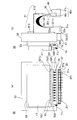
- a container group in which two or more reaction vessels are arranged, and a flexible link that can be directly or indirectly linked to each of the reaction vessels and optically connected to the inside of the linked reaction vessels.
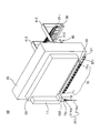
- a light guide gantry having two or more linking portions provided with one or two or more light guiding portions, and corresponding to each linking portion, the linking portion having its tip provided Two or more connection ends provided with the rear end of the light guide unit, and a connection end array having an array surface that supports the array by arranging along a predetermined path, and provided close to or in contact with the array surface,
- One or two or more measurement ends that can be sequentially optically connected to each connection end along the predetermined path, and an optical state in the reaction vessel by optical connection between the connection end and the measurement end
- a measuring instrument capable of receiving light based on the connection end, the connection ends arranged in the connection end array, and the measurement It is the optical measurement apparatus for reaction containers which has a light guide switching mechanism which moves relatively so that a fixed end may be optically connected sequential
- the container group preferably has two or more liquid storage units for storing liquids such as specimens and reagents in addition to the reaction containers.
- the container group includes a microplate in which wells as a plurality of liquid storage portions are arranged in a matrix or a row (row), and a cartridge-like container in which wells as a plurality of liquid storage portions are arranged in a row.
- the container group includes, for example, a specimen, a magnetic particle suspension in which magnetic particles capable of capturing a nucleic acid to be amplified or a fragment thereof are suspended, and separation and extraction of the amplification target. It has two or more liquid storage units for storing the separation / extraction solution used in the above and the amplification solution used for nucleic acid amplification.
- the “amplification solution” refers to a template DNA solution, a primer solution, a DNA polymerase solution, a nucleotide solution, a reaction buffer solution, etc. to be amplified when amplification is performed by PCR, for example, and amplification by SPIA
- a DNA / RNA chimera primer solution, a DNA polymerase solution, an RNase H solution, or the like is used.
- real-time PCR there are an intercalation method, a hybridization method, and a LUX method as methods that are usually performed using a fluorescent reagent containing a fluorescent substance.
- the “intercalation method” uses the property that fluorescent substances such as SYBR (registered trademark) GREEN I and ethidium bromide enter double-stranded DNA during the extension reaction and emit fluorescence when irradiated with excitation light. It is a method of measuring quantity. Therefore, the amplification solution contains at least the fluorescent substance and a quencher that suppresses light emission of the fluorescent substance.
- the “hybridization method” is a method of detecting only a target PCR product using a DNA probe labeled with a fluorescent substance in addition to a PCR primer. That is, the hybridized DNA (amount) is detected by hybridization of the fluorescently labeled DNA probe with the target PCR product.
- the “LUX method” utilizes the property that the fluorescent signal of a fluorescent substance labeled on an oligonucleic acid is influenced by the shape (sequence, single strand, double strand, etc.) of the oligonucleic acid.
- real-time PCR is performed using a PCR primer (LUX primer) labeled with one type of fluorescent substance and a PCR primer not labeled with anything.
- the LUX primer has a fluorescent substance labeled near the 3 ′ end and is designed to take a hairpin structure with the 5 ′ end. When the LUX primer has a hairpin structure, the quenching effect is released and the fluorescence signal increases. By measuring this signal increase, the amount of PCR product can be measured.
- Examples of materials such as a container including the reaction container and a lid include resins such as polyethylene, polypropylene, polystyrene, and acrylic, glass, metal, and metal compounds.
- the size of the container is, for example, a size that can accommodate a liquid of several ⁇ l to several hundreds of ⁇ l and can be inserted into the tip of the dispensing tip.
- the diameter of the size of one container is several millimeters to several tens of millimeters, and the depth is several millimeters to several tens of millimeters.
- the temperature inside the reaction vessel can be controlled by a temperature controller.
- the “temperature controller” has a temperature source capable of raising or lowering the temperature in the reaction container containing the liquid to be temperature controlled based on an external signal or the like.
- the block-like member is provided with, for example, a Peltier element, a heater, a cooling device, and the like.
- a thermal cycler using a Peltier element is preferable as the temperature controller. That is, the container group or stage is provided with a temperature control block whose temperature is raised or lowered by a Peltier element as a temperature source in contact with or close to a part (for example, the lower wall part) or the whole of the reaction container. It is preferable that the temperature is controlled by. It is also possible to perform isothermal amplification temperature control by the LAMP method.
- Temperature control means that a target liquid or container is maintained at one or two or more set predetermined temperatures for a set time in accordance with a set order. It is. The temperature controller is instructed by sending a corresponding signal based on a program.
- the “predetermined temperature” is a target temperature to be reached by an object such as a target liquid.
- a nucleic acid such as DNA contained in the liquid or an oligonucleotide that is a fragment of the nucleic acid is amplified by a PCR method.
- the predetermined temperature to be set is, for example, a temperature cycle performed by the PCR method, that is, each temperature necessary for DNA denaturation, annealing or hybridization, extension, about 94 ° C., 50 ° C. to 60 ° C. A temperature between 0 ° C and about 72 ° C.
- the SPIA method (trademark) it is set to a constant temperature, for example, 55 ° C.
- the predetermined temperature can be cooled by a temperature controller at a transition promoting temperature lower than these predetermined temperatures.
- a temperature controller at the time of transition from a predetermined temperature of low temperature to a predetermined temperature of high temperature, heating is performed at a temperature for promoting transition higher than these predetermined temperatures, thereby shortening the transition time and reducing one cycle time.
- transition-promoting temperature is the time required to maintain each temperature, and depends on the type of amplification method, the reagent and liquid amount used in the PCR method, the shape, material, size, thickness, etc.
- the total is, for example, several seconds to several tens of seconds
- the processing time of the entire PCR method is, for example, about several minutes to several tens of minutes.
- the transition time is also included in the predetermined time.
- the “linkage part” is a member that can be linked to the reaction vessel so that it can be released directly or indirectly via a sealing lid or the like.
- the linking portion is provided with a light guide tip that is optically connected to the inside of the reaction vessel and can guide light based on the optical state in the reaction vessel.
- linkage with the reaction vessel means that it is close to or connected to the opening, outer wall, outer bottom of the reaction vessel, or the attached sealing lid or sheath, etc.
- the “connection” includes contact, close contact, close contact, fitting, and mounting, and includes optical contact with the light guide. At least contact so that a connection is possible. This is because the light guide portion provided in the linkage portion and the inside of the reaction vessel are optically connected by this linkage.
- the tip of the light guide part is a hole formed in the plate-like part, a translucent part such as an optical fiber, a lens or the like
- a translucent part such as an optical fiber, a lens or the like
- a cylindrical member or the like provided so as to protrude from the light guide pedestal, and the distal end of the light guide portion is a cavity provided in the cylindrical member or the like, a transparent fiber such as an optical fiber.
- It is an optical system element such as a light part or a lens.
- the flexible light guide is, for example, an optical fiber or an optical fiber bundle. When measuring fluorescence, it has two or more light guides, a part of which is used for irradiation and the other for receiving light.
- the reaction vessel is sealed with mineral oil or the like.
- the linkage portion directly connects the reaction vessel to the reaction vessel. It is preferable to form it so that it can be sealed.
- the reaction vessel or its linking portion needs to have translucency.
- the “predetermined path” is a path on a plane or curved surface that allows the measurement end and the connection end array to move relative to each other so that all the connection ends arranged along the measurement end can be scanned.
- the path connecting all the connection ends is a path along a single or multiple non-intersecting line segments (including zigzag lines and closed lines), curves (including spirals and closed curves), or combinations thereof.
- each single or multiple path is continuous and is along a straight line without cusps or corners, or along a smooth curve with a curvature that can be traced by the measurement end.
- the linkage part and the connection end may correspond to one-to-one when they correspond to one-to-one, correspond to a plurality of one-to-one. In the middle of this, it is possible to branch or merge the light guide sections, or to branch or merge the light guide section bundle composed of a plurality of light guide sections.
- the predetermined path is preferably determined so that smooth scanning is possible based on the number, shape, arrangement, or size of the measurement end of the measuring instrument. For example, in the movement of the connection end with respect to the measurement end, a predetermined path along a straight line that does not change abruptly, for example, an obtuse or perpendicular direction with respect to the traveling direction, is preferable.
- the arrangement pattern of the linking portion is, for example, a matrix, a column, or a row
- the arrangement pattern of the connection ends is, for example, the same arrangement, a similar arrangement that differs only in size, or a different arrangement pattern, for example, There may be a circular shape, other closed curve shape, one column shape, or a matrix shape having a smaller number of columns or rows.
- the predetermined path is determined so as to pass through all the connection ends arranged.
- the arrangement of the connection ends is integrated with the arrangement of the linkage portions.
- the predetermined path (or the array pattern of the connection ends) is smaller or smaller than the area of the region surrounding the array pattern of the link portions of the light guide base or the interval between adjacent link portions. This is preferably done by reducing the total scanning distance.
- the speed is the same, it is possible to process in a shorter time than the case where the measurement end directly scans the linkage portion.
- the degree of integration is, for example, that the relative movement or scanning between the connection end array and the measuring device completes light reception from all reaction vessels to be measured within a stable light receiving time. It is preferable that it is possible.
- the “stable light receiving time” is a time during which the optical state capable of receiving light in the reaction container is stably maintained.
- a real-time PCR intercalation method, LUX method or hybridization In the case of the TaqMan probe of the method, this corresponds to the time during which the extension reaction of each cycle of PCR is performed. In the case of using a FRET probe in the hybridization method, the time for annealing is equivalent to this.
- this stable light receiving time is, for example, about several seconds to 10 seconds.
- the amount of fluorescence detected is below the detection limit in the initial cycle of the PCR reaction, and the latter cycle of the PCR reaction is in a plateau state, and in order to ensure quantification in a strict sense, exponential PCR amplification is observed. This is within the range of the amplification curve that can be produced.
- the present invention makes use of the fact that the stable light reception time can be used as the movement time between the reaction vessels at the measurement end, and the relative movement necessary for receiving the light from each reaction vessel is represented by this stable light reception.
- the “optical state” is a state such as light emission, coloration, color change, or light change.
- the light based on the optical state is light generated by light emission or change, reflected light or transmitted light of light applied to coloration or color change, scattered light, or the like.
- connection end and the measurement end sequentially means that the connection end and the measurement end are optically connected by facing each other at a close distance. Since the moment of connection corresponds to the maximum value of the amount of light received by the measuring instrument, the measurement control unit specifies data to be measured by calculating the maximum value of the amount of light.
- the “measuring device” enables measurement of, for example, fluorescence and chemiluminescence. In the former case, irradiation of one or more types of excitation light, one or more types of wavelengths are performed. Fluorescent light reception and a filter for this purpose. These are preferably guided using an optical fiber.
- the “measurement end” has at least an incident port for light to be received provided in the measuring instrument, and has an exit port for light to be irradiated in the case of fluorescence measurement. These can be provided as separate measuring ends.
- the entrance or exit is optically connected to a light receiving unit or irradiation source made of a photoelectric element provided inside. In that case, it can each connect via the light guide part for light reception, or the light guide part for irradiation.
- the connection end array, the measurement end, and the measuring device are provided at positions that are not in direct contact with or close to a reaction vessel or a mounting base on which heating control or temperature control is performed.
- the reaction vessel optical measurement device has a “measurement control unit” which is not explicitly described, and the “measurement control unit” controls the measuring device and the light guide switching mechanism, and the reaction vessel A computer (CPU) built in the optical measuring device and a program for driving the computer. For example, measurement control is performed by sending a signal to a nuclear control unit for driving the moving mechanism through a DA converter. .
- At the time of light reception by the measuring device at least the measuring device main body excluding the measuring end is provided immovably with respect to the reaction vessel and the light guide mount having a linking portion linked thereto.
- the reaction vessel optical measurement device at the time of light reception by the measuring device, at least the measuring device main body excluding the measuring end is provided immovably with respect to the reaction vessel and the light guide mount having a linking portion linked thereto.
- connection end array may move with respect to the measurement end, or the measurement end may move with respect to the connection end array, and the measuring instrument body is linked to the reaction vessel with the light guide base.
- the measuring instrument body is linked to the reaction vessel with the light guide base.
- it may be provided so as to be movable with respect to the reaction vessel or the light guide base.
- the measuring instrument main body is interlocked with the light guide base or when the measuring instrument main body is interlocked with movement in a part of the direction
- the measuring instrument main body is interlocked with the reaction container, or This is a case where the reaction vessel and the stage are fixed.
- the measurement end also includes a light guide portion that is outside the measuring instrument main body and extends to the measurement end if present.
- a gantry moving mechanism that moves the light guide gantry relative to the container group so that the linking portion is directly or indirectly linked to the two or more reaction vessels. It is the optical measuring device for reaction containers which has.
- the gantry moving mechanism presses the sealing lid mounted to cover the opening of the reaction container or Can be shaken. That is, it is preferable that the measurement control unit performs control so that the sealing lid is pressed or shaken after being indirectly linked with the linking portion via the sealing lid so as to cover the opening of the reaction vessel. .
- the reaction vessel can be securely sealed, and by shaking, the sealed state between the opening of the reaction vessel and the sealing lid can be quickly and easily released and opened. Therefore, high processing efficiency and reliability can be obtained.
- the linking part When the linking part is linked to the reaction container by being close to the reaction container, not directly or indirectly by connection such as fitting with the opening of the reaction container, the relative movement in the vertical direction By moving in the horizontal direction without performing the steps, the linkage between the linkage portion and the reaction vessel and the release thereof can be sequentially and smoothly repeated.
- two or more linking portions provided on the light guide pedestal can move in a horizontal direction with respect to the light guide pedestal in a state in which the two or more reaction vessels can be directly or indirectly linked together.
- the linkage between each linkage portion and the reaction vessel is extended in the horizontal direction in which each linkage portion can be inserted and the linkage portion array body is movable, and the light guide base is attached to each linkage portion.
- the linking part can be linked with the reaction vessel easily and at high speed only by moving in the horizontal direction without depending on the vertical movement of the light guide base. Accordingly, by setting the speed of the linking portion array so that it can be performed within the stable light receiving time including the horizontal movement of the linking portion array, one set of more reaction vessels can be obtained. With this measuring device, light reception and measurement can be performed substantially in parallel.
- the measuring instrument has one or more measuring ends that can be optically connected to the connecting ends, and can measure a plurality of types of specific wavelengths that can receive light of a specific wavelength or a specific wavelength band. And a measurement end alignment unit that aligns a plurality of measurement ends so as to be optically connectable to the connection ends along the predetermined path.
- the measuring device or each specific wavelength measuring device has an excitation light irradiation source for irradiating the corresponding excitation light and a light receiving unit.
- an irradiation port connected to the irradiation source and a light receiving port connected to the light receiving unit are provided as the same measurement end or separate measurement ends.
- an optical system element such as a cavity and a lens, and a light guide unit such as an optical fiber are provided.
- Measurement is performed integrally or in a chain. “Integrally” means that the measurement ends are arranged to be fixed to each other without any degree of freedom. “Chain” means that the measurement ends are arranged with a certain degree of freedom like a chain. In “alignment”, the measurement ends may be arranged along the scanning direction of the predetermined path or a direction perpendicular to the scanning direction. In the latter case, a plurality of paths are arranged in parallel as the predetermined path.
- a plurality of types of amplification targets can be amplified in parallel under the same conditions in one reaction vessel,
- multiplex PCR amplification or multiplex real-time PCR can be performed by using a primer labeled with a plurality of types of luminescent substances or the like.
- a fifth aspect of the present invention is a reaction container photometric device having a translucent sealing lid attached to the opening of one or more of the reaction containers and sealing the reaction containers in the container group. .
- the “sealing lid” includes not only a plate-like or block-like inflexible but also a flexible film-like or film-like one.
- the “mounting” includes fitting, screwing, friction, adsorption, adhesion, adhesion, and the like. In this case, it is preferable to detachably attach.
- each linking portion of the light guide base is linked at the opening of each reaction vessel, the linking portion or the nozzle is pressed or shaken against the sealing lid that covers the opening of the reaction vessel.
- the sealing lid that covers the opening of the reaction vessel.
- the linkage part is provided so as to protrude below the light guide base.
- the linkage portion has, for example, a rod shape, a cylindrical shape, a cone shape, or the like, and a lower end portion of the member can contact the sealing lid.
- One sealing lid covers one or more reaction container openings.
- the sealing lid is moved by being attached to a nozzle to be described later, and covers the opening of the reaction vessel using a chip detachment mechanism.
- one or more mounting recesses that can be mounted on one or more of the nozzles are provided on the upper side of the sealing lid.
- One or two or more of the linking portions can be inserted into the dent (which is also a dent for linking) by the vertical movement of the light guide base and linked to the reaction vessel.
- the reaction container optical measurement device includes, for example, a transport body movable with respect to the container group, a covering plate that covers the opening of each reaction container, and the light transmissive member.
- a sealing lid having a mounting portion that protrudes downward at a portion excluding the central portion of the covering plate and that can mount the covering plate on the reaction vessel, and is exposed to the lower side in a state where the mounting portion can be mounted on the reaction vessel.
- the cover plate is gripped as described above, and has a hermetic lid transport body having one or more grip portions arranged on the transport body in accordance with the arrangement of the reaction containers. Further, if the hermetic lid carrier is interlocked with the light guide base, the structure of the apparatus can be simplified and the scale of the apparatus can be prevented from being increased.
- the linking portion reacts on the sealing lid without depending on the vertical movement of the light guide base. It can be easily linked only by moving horizontally between the openings of the container. In this case, if the linking portion can be moved in the horizontal direction within the time during which stable light reception is possible, light reception and measurement can be performed in parallel in a larger number of reaction vessels.
- a sixth aspect of the present invention is a light measuring apparatus for a reaction container, wherein the light guide base has a heating part capable of heating the sealing lid.
- the measurement control unit controls the gantry moving mechanism so that the optical linking unit is indirectly linked to two or more reaction vessels simultaneously after the sealing lids are attached to the linking unit all at once. Thereafter, the heating unit is controlled to heat the sealing lid.
- the “heating unit” has a heating function at a temperature set by, for example, the magnitude of an applied current or based on on / off control.
- the heating of the sealing lid by the heating unit is performed to prevent condensation during temperature control of the reaction vessel sealed by the sealing lid.
- a temperature controller having a temperature source provided in contact with or close to a lower wall portion of the reaction vessel, and an upper portion of the reaction vessel positioned above the lower wall portion of the reaction vessel.
- a reaction container optical measurement device having a heating unit provided with a heating source provided in contact with or in proximity to the side wall portion and capable of heating the upper side wall portion.
- the “lower wall portion” is a wall portion including a bottom portion or a part of the wall portion that surrounds a volume portion that can accommodate a predetermined predetermined liquid amount of a part (for example, 1% to 90%) of the total volume of the reaction vessel. Part.
- the lower wall portion is, for example, a wall portion of a portion that can accommodate the liquid of the specified liquid amount.
- a reaction vessel composed of a wide-mouthed pipe part and a narrow-mouthed pipe part linked to the linkage part, it is provided in the narrow-mouthed pipe part.
- the “upper wall portion” is a container portion that surrounds the remaining volume of the lower container portion in which the specified liquid amount is accommodated, or a part thereof, out of the total capacity of the reaction vessel.
- the “upper wall portion” is usually preferably provided on the upper side of the reaction vessel spaced from the lower wall portion.
- the upper wall portion is closer to the opening, the sealing lid, or the linkage portion than the lower wall portion.
- an upper wall portion is provided on the wall portion of the wide-mouthed tube portion.
- the upper side wall portion is, for example, a portion corresponding to a strip shape along the circumference of the container wall.
- the measurement control unit controls the gantry moving mechanism so that the linking unit is directly or indirectly linked to the reaction vessel at once, and then prevents the linking unit from directly or indirectly condensing.
- Control the heating section “Indirect linkage” refers to the case where the linkage portion is linked to the reaction vessel via a sealing lid, the outer wall of the reaction vessel, or the like.
- “Control of the heating unit” is performed according to “temperature control” in order to prevent condensation.
- the heating temperature is several degrees (temperature exceeding the dew point of water vapor necessary for preventing condensation) to several tens of degrees Celsius (the melting point of the material in the reaction vessel) is sufficiently lower than each predetermined temperature set by temperature control. Temperature), for example, 1 ° C.
- heating is performed at a temperature higher than 94 ° C., for example, 100 ° C., and when isothermal is used, when the predetermined temperature is about 55 ° C., for example, several degrees higher than that. Heating is performed at a high temperature, for example, about 60 ° C to 70 ° C.
- the heating unit directly heats the reaction vessel instead of the linkage unit or the sealed unit, thereby reducing the thermal effect on the optical system element provided in the linkage unit or the measurement end near the linkage unit or
- the reliability of the image that can be obtained through the optical system element can be increased.
- various lenses such as a ball lens and an aspherical lens, which are the optical system elements, in the linking part, the light generated in the reaction container and emitted in the direction of the opening is reliably condensed to an optical fiber.
- the light can be incident on a light guide unit such as a light guide.
- a reaction vessel a temperature controller having a temperature source provided in contact with or in proximity to the lower wall portion of the reaction vessel, and controlling the temperature in the reaction vessel, and contacting the upper wall portion or
- a heating unit that is provided in the vicinity and has a heating source capable of heating the upper side wall portion constitutes a reaction vessel control system.
- the reaction vessel includes a wide-mouthed pipe part and a narrow-mouthed pipe part provided below the wide-mouthed pipe part and communicating with the wide-mouthed pipe part and formed narrower than the wide-mouthed pipe part.
- the portion can be fitted with the tip of the linkage portion, and the narrow mouth tube portion can contain liquid, the lower wall portion is provided in the narrow mouth tube portion, and the upper wall portion is provided in the wide mouth tube portion. It is preferred that Moreover, it is preferable that the contact surface between the upper part of the reaction vessel heated by the heating part or the sealing lid contacting the reaction container and the linkage part is as small as possible. As a result, the influence of the link portion on the optical system element by the heating portion can be reduced or eliminated.
- the light guide base is detachably mounted with a suction / discharge mechanism that sucks and discharges gas and a dispensing tip that can suck and discharge liquid by the suction / discharge mechanism.
- a suction / discharge mechanism that sucks and discharges gas
- a dispensing tip that can suck and discharge liquid by the suction / discharge mechanism.
- It is a light measuring device for reaction containers which is provided in the nozzle head which has this nozzle, and has a nozzle head moving mechanism which makes this nozzle head relatively movable between the said container groups.
- the suction / discharge mechanism, the moving mechanism, and the magnetic part are controlled to separate and extract the solution to be amplified from the sample as the reaction solution and store the liquid It is preferable to provide an extraction control unit that is housed as a part of the amplification solution in the unit.
- the “solution for separation and extraction” refers to a lysis solution that decomposes or dissolves a protein that forms a cell wall or the like contained in a specimen and causes nucleic acid or a fragment thereof to flow out of bacteria or cells, nucleic acid to the magnetic particles, or There are a buffer solution for facilitating the capture of the fragment, and a dissociation solution for dissociating the nucleic acid or the nucleic acid fragment captured by the magnetic particle from the magnetic particle. In order to separate the nucleic acid or a fragment thereof, it is preferable to repeat the suction and discharge of the mixed solution.
- the “dispensing tip” includes, for example, a large-diameter portion, a small-diameter portion, and a transition portion that communicates the large-diameter portion and the small-diameter portion. It has a mounting opening to be inserted and mounted on the nozzle, and the narrow-diameter portion has a front end opening through which liquid can flow in and out by suction and discharge of gas by the suction and discharge mechanism.
- the dispensing tip and the nozzle are made of, for example, organic materials such as resins such as polypropylene, polystyrene, polyester, and acrylic, metals such as glass, ceramics, and stainless steel, metal compounds, and inorganic materials such as semiconductors.
- the “suction / discharge mechanism” includes, for example, a cylinder, a piston sliding in the cylinder, a nut portion connected to the piston, a ball screw into which the nut portion is screwed, and the ball screw in both forward and reverse directions. It is formed by a motor that rotates.
- the two or more container groups correspond to each nozzle, and two or more dedicated areas corresponding to each nozzle that one nozzle enters and the other nozzle does not enter.
- the gantry moving mechanism uses at least a part of the nozzle head moving mechanism.
- the nozzle moving mechanism that moves the nozzle itself in the Z-axis direction also uses at least a part of the nozzle head moving mechanism, and the gantry moving mechanism and the nozzle moving mechanism can move independently with respect to movement in the Z-axis direction. Is preferred.
- a reaction container photometric device in which the nozzle can be held with a sealing lid attached, and the sealing lid can be attached to the opening of the reaction container by removing the sealing lid. is there.
- the sealing lid can be detached by a tip detaching mechanism that detaches the dispensing tip attached to the nozzle from the nozzle.
- the “sealing lid” has a sealing portion that can be attached to the opening of the reaction vessel and a recess for connection that can be attached to the nozzle.
- the linkage lid is used for the linkage.
- the depression is preferably fitted and attached to the tip of the linkage part instead of the nozzle so that the linkage part can hold the sealing lid.
- each link portion is provided with a leading end of a light guide portion bundle composed of a plurality of light guide portions, and a rear end of a part of the light guide portion bundle of the light guide portion bundle has the connection end arrangement Provided at the first connection end of the body, the remaining part or all of the light guide section bundle is provided at the second connection end of the connection end array, and the predetermined path includes the first path and the first path.
- the first measurement end provided on the measuring instrument is moved along the first path consisting of the first connection end by the movement of the connection end array.
- a reaction vessel optical measuring device that moves relatively along a second path formed by the second connection end.
- the first measurement end is optically connected to an irradiation source of the measuring device
- the second measurement end is connected to a light receiving unit of the measuring device
- the first connection The tip corresponding to the end and the tip corresponding to the second connection end are arranged so as to coexist, the first measurement end is connectable to the first connection end, and the second measurement end
- the end is a light measuring device for a reaction vessel that can be connected to the second connection end.
- the “mixing of the tips” is preferably arranged so that the tips of two or more light guides are mixed so that they are homogenized.
- the container group includes two or more dedicated areas corresponding to each set of nozzles in which one set of nozzles including one or more of the nozzles enters and other sets of nozzles do not enter.
- each dedicated region at least one of the reaction containers, one or two or more liquid storage units that store the reaction solution used for the reaction, and can be transported to the reaction container using the nozzle, and the reaction container At least a sealing lid capable of sealing the reaction solution accommodated in each of the light guide racks, and each of the link portions of the light guide base enters a set of one or more link portions into each of the dedicated areas.
- the light guide pedestal is a light measuring device for a reaction vessel that is extended over the entire exclusive area so that other sets of linkage portions are associated with each other so as not to enter.
- the dedicated areas The nozzle head moving mechanism is controlled so that one set of the nozzles enters and the other set of nozzles does not enter, and one set of the linkage parts enters the other dedicated area and the other set of linkage parts enters. This is done by providing a dedicated area control unit for controlling so as not to occur.
- the optical measurement for a reaction vessel further includes a pair of traversable nozzles each including one or two or more nozzles that are movable so as to traverse each of the dedicated areas and can enter each dedicated area. Device.
- specimen information for identifying or managing a specimen and examination information indicating examination contents are visually displayed in each dedicated area, and each dedicated area including the specimen information and the examination information is displayed.
- a digital camera that captures the displayed content and obtains image data is a light measuring device for a reaction vessel provided in the crossable nozzle.
- specimen information is information necessary for identifying or managing a specimen.
- information for identifying a specimen include a patient, animal, foodstuff, soil, sewage from which the specimen is collected.
- Specimen attributes such as patient name, age, gender, ID number, food sales location, soil collection location, collection date and time, or sample physical properties such as patient blood, urine, feces , Body fluid, cell type, food type, soil type, sewage type, and the like.
- the information for managing the sample includes, for example, the sampler of the sample, the collection date, the person in charge of the test for the sample, the date of the test for the sample, and the like.
- Test information is information indicating the content of a test performed on a specimen, and includes, for example, test items, for example, various gene information (for example, SNPs, nucleotide sequence determination), genetic diagnosis, or other various proteins.
- Information or the type of reagent used in the test, the reagent production lot number, the calibration curve of the reagent, or the type, structure, type of biological substance fixed on the carrier, etc. can be contained.
- Such information is displayed by handwriting, when printed, by barcode, or by QR (registered trademark) code (matrix two-dimensional code). The image data is analyzed, converted into analysis data corresponding to the code data, and output.
- a fifteenth aspect of the invention is a nozzle provided with one or more nozzles for detachably mounting a suction / discharge mechanism for sucking and discharging a gas and a dispensing tip capable of sucking and discharging a liquid by the suction / discharge mechanism Head, one or more liquid storage units for storing reaction solutions used for various reactions, liquid storage unit for storing magnetic particle suspensions in which magnetic particles capable of capturing target substances are suspended, and samples
- a container group having at least one or two or more liquid container parts for containing a solution for separating and extracting a target substance, and two or more reaction containers, and a relative relationship between the nozzle head and the container group.
- a nozzle head moving mechanism that can move to the nozzle, a magnetic part that can adsorb the magnetic particles on the inner wall of each dispensing tip attached to the nozzle, and a nozzle head that is directly or directly connected to each reaction vessel.
- a gantry and two or more connection ends provided corresponding to each of the linking portions and provided with a rear end of the light guide portion provided with a tip of the linking portion are arranged along a predetermined path.
- connection end array having an array surface to be supported, and one or two or more measurement ends that are provided close to or in contact with the array surface and can be sequentially optically connected to each connection end along the predetermined path.
- a measuring instrument capable of receiving light based on the optical state in the reaction vessel by optical connection between the connection end and the measurement end, and provided along the predetermined path of the connection end array A light guide that relatively moves so as to sequentially optically connect each connection end and each measurement end.
- conversion mechanism a reaction vessel for light measurement apparatus having a.
- the “reaction solution” is, for example, an amplification solution used for nucleic acid amplification
- the “target substance” is a nucleic acid to be amplified or a fragment thereof.
- a chip detachment mechanism for detaching the sealing lid or the dispensing tip from the nozzle.
- a sample supply device having a dispensing function for supplying the sample, reagent, cleaning liquid, buffer, etc. necessary for the container group is provided at a position different from the stage of the reaction container optical measurement device. It is preferable that each stage in which the container group is incorporated is automatically moved to the position of the stage of the light measuring device for reaction container so as to be replaceable. Thereby, it can process consistently including preparatory processes, such as a dispensing process to a container group, and a supply process.
- Each of the second to thirteenth inventions can be combined with the present invention.
- a sixteenth aspect of the present invention there are provided two or more reaction parts arranged in a container group and having two or more linkage parts provided with one or more flexible light guide part tips.
- the gantry is moved, the reaction vessel and the linking portion are linked together directly or indirectly, the linked reaction vessel interior and the light guide are optically connected, and the temperature in the reaction vessel is increased.
- Control light from the reaction vessel is provided corresponding to each link portion, two or more connection ends provided at the rear end of the light guide portion provided at the tip of the link portion
- One or two or more measurement ends provided on a measuring instrument and each connection provided to a connection end array having an arrangement surface to be arranged and supported along a predetermined path.
- the connection end array By moving the connection end array, the optical ends are sequentially optically connected along the predetermined path. It is the light measuring method for reaction containers in which the measuring device receives the light based on the optical state in the said reaction container.
- Each of the second to thirteenth inventions can be combined with the present invention.
- the measuring device has a plurality of types of specific wavelength measuring devices capable of receiving light of a specific wavelength or a specific wavelength band, and each specific wavelength measuring device is sequentially provided along each connection end and the predetermined path. And at least one measurement end that can be optically connected, and each of the plurality of measurement ends is aligned by a measurement end alignment unit, and each of the measurement ends is sequentially optically connected to each of the connection ends along the path.
- each specific wavelength measuring device is the optical measurement method for reaction containers which receives the light of the specific wavelength or specific wavelength band based on the optical state in the said reaction container.
- the light guide gantry is mounted after simultaneously attaching two or more sealing lids arranged in the container group and having translucency that can be fitted to the opening of the reaction container to the reaction container. Is a light measurement method for a reaction container in which the reaction container is moved with respect to each sealing lid of the reaction container.
- a nineteenth aspect of the invention is a light measurement method for a reaction container in which the sealing lid that covers the opening of the reaction container is pressed or shaken.
- the twentieth aspect of the invention is a light measurement method for a reaction container in which a sealing lid for sealing the reaction container is heated through the light guide mount.
- the contact with the lower wall portion of the reaction vessel when controlling the temperature in the reaction vessel by directly or indirectly linking each opening of the reaction vessel and the linking portion, the contact with the lower wall portion of the reaction vessel Alternatively, depending on the temperature control of the temperature controller having a temperature source provided in close proximity, the upper wall portion of the reaction vessel located above the lower wall portion is brought into contact with or close to the upper wall portion. It is a light measurement method for a reaction container that is heated by a heating source of a provided heating unit to prevent direct or indirect condensation of the linkage unit.
- a nozzle that removably attaches a dispensing tip to each nozzle that sucks and discharges gas provided in a nozzle head, and moves relatively between a magnetic part and the nozzle head and a container group.
- the target substance is separated using a head moving mechanism, a magnetic particle suspension in which magnetic particles capable of capturing the target substance contained in a container group are suspended, a specimen, and a target substance separation and extraction solution.
- a substance and a reaction solution used for reaction are introduced into a plurality of reaction containers provided in a container group, and the tip of one or more light guides is provided in the nozzle head with respect to the opening of the reaction container
- the light guide gantry having two or more linking portions provided with is moved by at least the nozzle head moving mechanism, and each opening of the reaction vessel and the linking portion are linked together directly or indirectly. Work together
- the inside of the reaction vessel and the light guide unit are optically connected, temperature control is performed in the reaction vessel, and light from the reaction vessel is provided corresponding to each linkage unit,
- the two or more connection ends provided with the rear end of the light guide portion provided with the tip thereof are guided along a predetermined path to a connection end array, and are provided close to or in contact with the arrangement surface.
- the one or two or more measurement ends provided in the measuring instrument and the respective connection ends are moved relative to each other so that they are sequentially optically connected along the predetermined path. It is a light measurement method for reaction measurement in which a measuring device receives light based on an optical state.
- a measuring device receives light based on an optical state.
- a plurality of reaction vessels are optically connected to the inside of the reaction vessel by being linked by the linkage portion provided on the light guide base.
- the optical state in the reaction container is transmitted to the connection end of the array surface of the connection end array through the plurality of reaction containers, the light guide base and the light guide by connecting, and the array of the connection end array.
- connection end can be rearranged to ensure reliable, quick and smooth connection to the end of the measurement, providing reliable measurements and more efficient and quick measurement of the optical state in the reaction vessel. Can be done.
- the distance between the entire connection end arrangement region or the adjacent connection ends is made smaller than the arrangement region of the linkage part or the adjacent distance. This can be achieved by integration or by smoothing the movement of the measurement end by linearizing a predetermined path or enlarging the radius of curvature as compared with the arrangement of the linking portions.
- the structure of the optical system can be simplified.
- the connection end, measurement end, and measuring instrument away from the reaction vessel and light guide base where temperature control and heating control are performed the thermal influence of the optical elements is eliminated and reliable processing is performed. Can do.
- the movement of the connection end with respect to the measurement end includes continuous or intermittent movement.
- an amplification curve can be prepared and used for various analyzes such as determination of the initial concentration of DNA.
- the measuring instrument moves the reaction container and the light guide cradle associated therewith when moving with respect to the connection ends and the measurement ends arranged in the connection end array. Therefore, during measurement, the optical system elements and electronic system elements built in the measuring instrument body are not subjected to inertial force due to acceleration caused by movement, etc. System elements can be prevented from being destroyed and highly reliable and precise measurement can be performed. In cases other than measurement, the measuring instrument main body can be moved with respect to the reaction container or the like, so that the measuring instrument can be carried near the reaction container for measurement.
- each reaction container can be connected to the reaction portion without manual intervention. Can be linked directly or indirectly all at once, so that cross-contamination can be prevented and processing can be performed efficiently.
- a plurality of types of luminescent materials, color developing materials, color changing materials, or light changing materials in one reaction vessel for example, a plurality of types of amplification targets can be When performing amplification in parallel under the same conditions in a reaction vessel, multiplex PCR amplification and multiplex real-time PCR can be performed on multiple types of amplification targets by using primers labeled with multiple types of luminescent substances, etc. is there.
- a mechanism for switching the reception of light of a plurality of types of specific wavelengths or a specific wavelength band from a plurality of types of luminescent substances, etc., when moving between a plurality of reaction vessels using a stable light reception time By using both, it is not necessary to separately provide a special light switching mechanism, the apparatus mechanism can be simplified, and the manufacturing cost can be reduced. Furthermore, since each specific wavelength measuring device receives light of a single specific wavelength or specific wavelength band, it is possible to perform high-precision measurement without being affected by other specific wavelengths or specific wavelength bands. it can. In addition, since each specific wavelength measuring device can be modularized for removal and addition, highly versatile processing according to the processing purpose can be performed.
- the sealing lid arranged in the container group it is possible to attach the sealing lid arranged in the container group to the opening of the reaction container by moving the nozzle head or the like by attaching the sealing lid to the linkage part or the nozzle. Therefore, since the contents in the reaction container do not directly contact the linking part of the gantry, cross contamination can be effectively prevented. Moreover, since it is not necessary to provide a dedicated mechanism for mounting the hermetic lid on the reaction vessel, the scale of the apparatus is not increased and the manufacturing cost is reduced.
- the reaction container can be reliably sealed by controlling to press the sealing lid covering the opening of the reaction container. Moreover, by shaking the sealing lid, the sealed state between the opening of the reaction vessel and the sealing lid can be quickly and easily released and opened. Therefore, high processing efficiency and reliability can be obtained.
- direct or indirect dew condensation on the linking portion is performed by heating the upper wall portion of the reaction vessel according to the temperature control of the lower wall portion of the reaction vessel. Can be prevented.
- the heating is performed on the upper side wall portion of the reaction vessel, not directly on the linkage portion or the sealing lid, direct heating to the optical system element provided on the linkage portion is performed. Can be reduced or eliminated.
- image distortion and the like due to deterioration and alteration of the optical system elements can be reduced or removed, and various optical system elements can be provided in the linking portion, so that accurate and versatile measurement can be performed.
- the light guide gantry is incorporated into a nozzle head provided with a nozzle, so that a mechanism for moving between reaction vessels of the measuring instrument (at least the X-axis) And the Y-axis direction) can be shared with the nozzle moving mechanism, so that the scale of the apparatus can be prevented from being increased.
- the sample solution, reagent solution, and reaction solution to be stored in the reaction vessel to be measured can be transferred to the reaction vessel and prepared using the function of the nozzle, the process from the measurement object to the measurement can be performed. Can be done consistently efficiently and quickly.
- the existing scale is used to prevent the expansion of the apparatus scale without providing a new dedicated lid transfer mechanism. be able to.
- the sealing lid is attached to the linking part and transferred or held, the diameters of the linking part and the nozzle can be made different. Therefore, highly versatile and reliable processing can be performed.
- the leading end of the bundle of light guide parts composed of a plurality of light guide parts is provided in each linkage part, the light guide part bundle is divided into a plurality of bundles, and the rear end of each light guide part Is divided into multiple connection ends, so that multiple measurement ends with one or more measuring instruments can be connected simultaneously to receive multiple types of wavelengths or wavelength bands, irradiation of excitation light to the reaction vessel, and reception Can be performed simultaneously, so that multiple fluorescence treatments can be performed.
- the first measurement end is optically connected to the irradiation source of the measuring instrument
- the second measurement end is optically connected to the light receiving unit of the measuring instrument, and the irradiation source
- the same target substance or sample such as the same nucleic acid can be dispensed to a plurality of dedicated regions by the same.
- the target substances and specimens can be used for reactions with different conditions.
- the movement of the traversable nozzle is also used as the moving mechanism of the connection end array, whereby the scale of the apparatus can be suppressed.
- information is displayed in each dedicated area, and the information displayed in each dedicated area is read by the camera along with the movement of the crossable nozzle, so that the reliability can be increased without increasing the scale of the apparatus.
- a highly reactive reaction and measurement process can be performed.
- FIG. 1 It is a whole block diagram which shows the optical measurement apparatus for reaction containers which concerns on the 1st Embodiment of this invention. It is a whole perspective view which shows the optical measurement apparatus for reaction containers which concerns on the example of 1st Embodiment. It is a top view which expands and shows the container group of the optical measurement apparatus for reaction containers shown in FIG. It is the front view and side view which expand and show the whole nozzle head of the optical measurement apparatus for reaction containers shown in FIG. It is the perspective view seen from the front side of the nozzle head shown in FIG. It is a side view which shows more specifically the moving mechanism and suction / discharge mechanism shown in FIG. It is a perspective view which shows more specifically the suction discharge mechanism 53 etc. which are shown in FIG.
- FIG. 12 is an enlarged perspective view in which a part of the light guide mount shown in FIG. 11 is cut away. It is an expanded sectional view of the connection part shown in FIG. It is sectional drawing which shows the example of the sealing lid shown in FIG.
- FIG. 12 is an enlarged perspective view of the hermetic lid carrier shown in FIG. 11.
- FIG. 20 is a side view specifically showing the moving mechanism and the suction / discharge mechanism according to the first exemplary embodiment of FIG. 19.
- FIG. 20 is a cross-sectional view showing a state in which the linking portion according to the first embodiment in FIG. 19 is linked to the reaction vessel.
- FIG. 20 is a cross-sectional view showing a state in which the linking part according to the second embodiment in FIG. 19 is linked to the reaction vessel.
- FIG. 20 is a cross-sectional view showing a state in which the linking part according to the third embodiment in FIG. 19 is linked to the reaction vessel.
- FIG. 1 shows a block diagram of a reaction vessel optical measurement apparatus 10 according to a first embodiment of the present invention.
- the nozzle array part 70 in which a plurality of (in this example, twelve) nozzles 71 i are detachably mounted and the respective opening portions of the reaction vessels can be directly or indirectly linked.
- a light guide base 32 having a plurality of (in this example, twelve) linkage portions 31 i provided with tips of two or more flexible light guide portions that are optically connected to the inside of the reaction vessel.
- Nozzle head 50 measuring instrument 40 fixed to the nozzle head 50, a nozzle head moving mechanism 51 that enables the nozzle head 50 to move, for example, in the X-axis direction, and a reaction vessel of the container group Temperature controller 2 for performing predetermined temperature control for group 23 i 9,
- CPU + ROM 60 including a CPU, a ROM, a RAM, various external memories, a communication function such as a LAN, a program stored in the ROM, and the like, and a display unit such as a liquid crystal display, an operation key, and an operation unit such as a touch panel And an operation panel 13 having.
- the nozzle head 50 includes a gantry Z-axis moving mechanism 35 that allows the light guide gantry 32 to move in the Z-axis direction with respect to the container group 20 independently of the nozzle array unit 70, and the gantry 32.
- a nozzle Z-axis moving mechanism 75 that enables the nozzle array unit 70 to move independently in the Z-axis with respect to the container group 20, and a small-diameter portion 211 of a dispensing tip 211 i that is detachably attached to the nozzle 71 i.
- a magnet 571 provided to be separable into a magnetic portion 57 capable of exerting and removing a magnetic field therein, to perform suction and discharge of gas into the nozzle 71 i with respect to the nozzle 71 i
- a suction / discharge mechanism 53 that enables suction / discharge of liquid to the dispenser tip 211 i that is mounted, and an opening of each liquid storage section of the container group 20 that is driven by the suction / discharge mechanism 53 is previously covered.
- each A perforating mechanism 55 for perforating a film containing the seed liquid.
- the gantry moving mechanism corresponds to the nozzle head moving mechanism and the gantry Z-axis moving mechanism.
- the said nozzle head 50 further, the provided corresponding to each of the linkage portion 31 i, an optical fiber (bundle) 33 i rear end of the light guide portion to which the tip end is provided on ⁇ engagement portion 31 i
- the plurality of (in this example, twelve) connecting ends 34 i provided are arranged along a predetermined path (in this example, a straight path along the Y-axis direction) provided on the vertical plane as an array surface.
- the connection end array 30 is arranged and supported so as to be integrated at intervals smaller than the interval between the linkage portions 31 i .
- the connection end array 30 is provided at a position away from the light guide base 32 and the reaction vessel group 23 i .
- the measuring device 40 can receive light of specific wavelengths or specific wavelength bands of six types of fluorescence, and irradiates excitation light of six types of specific wavelengths or specific wavelength bands to be emitted for light emission.
- There are six types of specific wavelength measuring devices 40 j (j 1,..., 6, omitted hereinafter).
- Each specific wavelength measuring device 40 j is provided close to or in contact with the arrangement surface, and can be sequentially connected to each connection end 34 i along the predetermined path (a linear path along the Y-axis direction).
- a measuring end 44 j the measuring portion 44 j has a first measuring portion 42 j and the second measuring portion 43 j of two arranged along the Y-axis direction.
- the first measurement end 42 j is optically connected to an irradiation source provided in each specific wavelength measuring device 40 j
- the second measurement end 43 j is provided in the specific wavelength measuring device 40 j . It is optically connected to a photoelectric element such as a photomultiplier tube.
- connection end array 30 is connected to the nozzle head 50 in such a manner that the connection ends 34 i arranged in the connection end array 30 and the measurement ends 44 j are sequentially connected.
- An array Y-axis moving mechanism 41 is provided as a light guide switching mechanism that moves on the nozzle head 50 along the direction.
- the light guide base 32 includes a heater 37 as the heating unit for heating to prevent condensation of the tip of the linking unit 31 i or the light-transmitting sealing lid 251 i attached thereto. .
- the container group 20 is composed of a plurality of (in this example, 12) dedicated areas 20 i corresponding to each nozzle in which one (one set corresponds to one in this example) enters and the other nozzle does not enter.
- Each dedicated region 20 i includes a liquid storage unit group 27 i composed of a plurality of storage units that can store or store reagent solutions and the like, and one or more translucent members that are detachably attached to the nozzles.
- a sealing lid accommodating portion 25 i that can accommodate or accommodate the sealing lid 251 i , a plurality of dispensing tips 211 i that are detachably attached to the nozzles, a tip accommodating portion group 21 i that accommodates a specimen, and the like.
- the liquid storage unit group 27 i includes at least one or more liquid storage units that store magnetic particle suspensions, and two or more liquid storages that store separation and extraction solutions used for separation and extraction of nucleic acids or fragments thereof. If necessary, two or more liquid storage units for storing the amplification solution used for nucleic acid amplification, and the amplification solution stored in the PCR tube 231 i as the reaction container are used for the PCR.
- the tube 231 i has a liquid storage portion for storing a sealing liquid for sealing.
- each dedicated area 20 i is preferably a bar code as the specimen information and examination information for identifying each dedicated region 20 i are displayed.
- the nozzle head 50, the exclusive region 20 i across the (moving in the Y-axis direction) provided crossable nozzles 71 0 of the liquid of the transfer or dispensable 1, wherein the suction and discharge mechanism 53
- the suction and discharge mechanism 17 separate from the above is used to perform suction and discharge.
- a solution such as DNA accommodated in one dedicated area 20 i can be dispensed and delivered to another dedicated area 20 K (k ⁇ i).
- the movement in the Y-axis direction is preferably shared by the array body Y-axis moving mechanism 41.
- the CPU + program 60 gives instructions for a series of processing such as extraction, amplification, and sealing of the amplification solution for the nucleic acid or a fragment thereof, the temperature controller 29, the nozzle head moving mechanism 51, the chip detaching mechanism 59, the suction.
- an optical fiber (bundle) 33 i as the light guide portion of the linkage portion 31 i the first measurement end 42 j, controlling the array Y-axis moving mechanism 41 so that the second measuring portion 43 j optically connecting child to be described later of the measuring device 40 j of the measuring portion 44 j
- the nucleic acid processing control unit 63 includes an extraction control unit 65 and a sealing lid control unit 67.
- the extraction control unit 65 includes the chip detachment mechanism 59, the suction / discharge mechanism 53, the magnetic force unit 57, and the nozzle Z axis.
- An extraction control unit 65 that instructs the moving mechanism 75, the nozzle head moving mechanism 51, and the gantry Z-axis moving mechanism 35 to perform a series of processing for extracting the nucleic acid or a fragment thereof, and the gantry Z-axis moving mechanism 35 and the nozzle
- a sealing lid control unit 67 that instructs the head moving mechanism 51 about the sealing process by the sealing lid.
- FIG. 2 is a perspective view showing the appearance of the reaction container optical measurement device 10 according to the first embodiment of the present invention.
- FIG. 2 (a) shows the appearance of the reaction vessel optical measuring device 10, for example, 500 mm in length (Y-axis direction), 600 mm in width (X-axis direction), and 600 mm in height (Z-axis direction).
- the housing 11 accommodates the container group 20, the nozzle head 50, the nozzle head moving mechanism 51 described with reference to FIG. 1, and the CPU + program 60, and the housing 11. It has an operation panel 13 and a drawer 15 provided with a stage.
- FIG. 2B is a perspective view of the inside of the housing 11, wherein a stage in which the container group 20 is incorporated is provided so as to be able to be pulled out by the drawer 15, and the nozzle head 50 is With respect to the container group 20, the nozzle head moving mechanism 51 of FIG.
- the nozzle head 50 is broadly divided into various moving mechanisms 52 including the array body Y-axis moving mechanism 41, the gantry Z-axis moving mechanism 35, and the nozzle Z-axis moving mechanism 75, and a crossable nozzle. It is shown that the suction / discharge mechanism 17, the measuring device 40, the connection end array 30, the optical fiber (bundle) 33 i, and the magnetic force part 57 are included.
- the crossable nozzle suction and discharge mechanism 17 and the crossable nozzles 71 0, by the array Y-axis moving mechanism 41 is supported so as to be movable in the Y-axis direction so as to cross the exclusive region 20 i ing.
- FIG. 3 is an enlarged plan view showing the container group 20 shown in FIG.
- Each dedicated area 20 i is provided with a cartridge container 201 i for PCR amplification, a cartridge container 202 i for nucleic acid extraction, and a cartridge container 203 i for chip accommodation separately.
- cartridge container 201 i, 202 i, 203 i partition wall 201 on one side of the rim along the X-axis direction of 0, 202 0, 203 0 of each dedicated area 20i is provided, the cross between the dedicated area 20 i It is intended to prevent contamination.
- the PCR amplification cartridge container 201 1 is linked via the sealing lid 251 i of 1 with translucent by detachable into 12 of the connecting portion 31 i provided on the light-guiding cradle 32
- the PCR tube 231 i as the reaction container, a liquid storage portion 271 i for storing a buffer solution necessary for the PCR reaction, a sealing lid storage portion 25 i for storing the sealing lid 251 i , and the PCR tube 231. and i and the liquid storage portion 271 chips accommodating portion 21 i housing the perforating tip and dispensing tip 211 i for perforating a film covering the i, and the specimen information relating to the PCR amplification cartridge container 201 i A barcode 81 i for displaying inspection information.
- the cartridge container 202 i for nucleic acid extraction contains, for example, seven liquid storage portions 272 i for storing various reagents for nucleic acid extraction, a reaction container 232 i for storing extracted nucleic acids, and the cartridge container It has a bar code 82 i for displaying various information, for example, specimen information and examination information.
- the temperature of the PCR tube 231 i and the reaction vessel 232 i can be controlled by the temperature controller 29.
- the chip housing cartridge container 203 i includes a perforating chip capable of perforating a film covering the nucleic acid extraction cartridge container 202 i , two small volume dispensing chips for dispensing a small amount of liquid, and an external magnetic force.
- the capacity of the PCR tube 231 i as the reaction container is about 200 ⁇ L, and the capacity of each of the other reaction containers, each solution storage section and the tube is about 2 mL.
- the PCR tube 231 i is used for amplification of a nucleic acid or a fragment thereof, and temperature control is performed by the temperature controller 29 based on a predetermined amplification method such as a thermal cycle (4 ° C. to 95 ° C.), for example. .
- a predetermined amplification method such as a thermal cycle (4 ° C. to 95 ° C.), for example.
- the PCR tube 231 i is formed in two stages, and is provided on the lower side and the narrow tube part 233 i that accommodates the amplification solution 234 i is provided on the upper side and the And a wide-mouthed pipe portion 235 i to which the sealing lid 251 i can be fitted.
- the inner diameter of the wide mouth tube section 235i for example 8 mm, inner diameter of the opening of the narrow mouth pipe portion 233 i is, for example, about 5 mm.
- the temperature is controlled to, for example, a constant temperature of 55 ° C. for incubation.
- the solution for separation and extraction is stored as follows.
- the first liquid container has Lysis 1 of 40 ⁇ L
- the second liquid container has Lysis 2 of 200 ⁇ L
- the third liquid container has 500 ⁇ L of binding buffer solution
- the fourth liquid container has In the magnetic particle suspension
- the fifth liquid storage part 700 ⁇ L of the cleaning liquid 1, in the sixth liquid storage part, 700 ⁇ L of the cleaning liquid 2
- in the seventh liquid storage part 50 ⁇ L of distilled water as a dissociation liquid
- 1300 ⁇ L of isopropyl alcohol (isopropanol) used for protein removal or the like is accommodated in the eighth liquid storage section which is stored and slightly separated as a part of the protein separation and extraction solution.
- Each of the openings is pre-packed with a film that can be perforated.
- 1.2 mL of distilled water is stored in a separate distilled water tank, and a tube for storing a specimen such as a suspension of bacteria or cells or whole blood is separately prepared for each dedicated region 20 i .
- the nozzle head 50 includes a nozzle array unit 70 in which twelve nozzles 71 i are arranged, a tip detachment mechanism 59 that can detach the dispensing tip 211 i attached to the nozzle 71 i , a suction / discharge mechanism 53, and the like.
- the magnetic part 57 having twelve magnets 571 provided so as to be able to contact and separate from the dispensing tip 211 i , the light guide base 32, and the twelve linkages provided on the light guide base 32.
- moving mechanism part 52 having nozzle Z-axis moving mechanism 75 and gantry Z-axis moving mechanism 35, and an optical fiber (bundle) as a flexible light guide extending rearward from linking part 31 i and 33 i, and the connecting terminal array 30, the sequence element Y axis moving mechanism 41, a meter 40 having a measuring portion 44, and can be traversed nozzle 71 0, and the suction and discharge mechanism 17, and has a .
- the nozzle array portion 70 is provided with a cylinder support member 73 that supports 12 cylinders 531 i arranged at a predetermined pitch, for example, 18 mm along the Y-axis direction, below each cylinder 531 i .
- the nozzle 71 i is provided at the tip of the cylinder 531 so as to communicate with the cylinder 531 i .
- Chip detaching mechanism 59 includes a chip detachment member 591 to desorb from the nozzle 71 i by the dispensing tip 211 i twelve desorption shaft 593 are provided on both sides, to slide up and down direction.
- the tip detaching member 591 detaches the dispensing tip 211 i from the nozzle 71 i in conjunction with the lowering of the two tip detaching shafts 593.
- the tip detaching shaft 593 is elastically supported by the cylinder support member 73 by a spring 600 wound around the outer periphery so as to be urged upward, and is above the upper end of the cylinder 531 i .
- the upper end of the cylinder drive plate 536 which will be described later, is located below the lower limit position of the normal suction / discharge vertical movement range.
- the two tip detaching shafts 593 are pushed downward by the cylinder drive plate 536 exceeding the vertical movement range and close to the upper end of the cylinder 531 i to lower the tip detaching member 591.
- the chip desorption The member 591, the nozzle 71 i 12 amino holes the nozzle is greater than the outer diameter with the dispensing tip 211 i maximum outer inner diameter smaller than the mounting portion 211 i c is the diameter of the 71 They are arranged at the pitch so that i penetrates.
- the suction / discharge mechanism 53 communicates with the nozzle 71 i and sucks and discharges gas to the inside of the dispensing tip 211 i attached to the nozzle 71 i.
- a piston rod 532 which slides the cylinder 531 i and the cylinder 531 in the i for a driving plate 536 which drives the piston rod 532, the ball screw 533 screwed with the drive plate 536, the ball A nozzle Z-axis moving body 535 that supports the screw 533 and is formed integrally with the cylinder support member 73, and a motor 534 that is mounted on the nozzle Z-axis moving body 535 and rotates the ball screw 533.
- the magnetic force part 57 is provided so as to be able to come into contact with and separate from the small-diameter part 211 i a of the dispensing tip 211 i detachably attached to the nozzle 71 i and exerts a magnetic field on the dispensing tip 211 i and is removed. It has a magnet 571 that can do this.
- the nozzle Z-axis moving mechanism 75 is screwed with the nozzle Z-axis moving body 535 to move the Z-axis moving body 535 up and down along the Z-axis direction.
- a nozzle head base that supports the ball screw 752 and supports the magnet 571 movably in the X-axis direction and is movable in the X-axis direction by a nozzle head moving mechanism 51 described later. 753 and a motor 751 provided on the upper side of the nozzle head base 753 and rotationally driving the ball screw 752.
- the light guide base 32 includes a horizontal plate 32 a having a L-shaped cross section and a vertical plate 32 b, and directly or directly with each opening of the PCR tube 231 i.
- a indirectly linkable, twelve cylindrical connecting portion 31 i is the horizontal plate 32a having a tip of coordinated optical fiber (bundle) 33 i to connect the PCR tubes 231 i inside and optically has Projecting downward.
- the root of ⁇ engagement portion 31 i, the heater 37 to prevent condensation by heating the sealing lid 251 i to be attached to ⁇ engagement portion 31 i is built.
- the temperature of the heater 37 is set to about 105 ° C., for example.
- the light guide base 32 Since the light guide base 32 is supported on the nozzle head base 753 so as to be movable in the Z-axis direction by the nozzle head base Z-axis moving mechanism 35, the light guide base 32 is movable in the nozzle X-axis direction and the Z-axis direction. .
- the gantry Z-axis moving mechanism 35 includes a timing belt that is stretched between a side plate 355 provided on the nozzle head base body 753 and two chain gears 353 that are axially supported by the side plate 355.
- a gantry driving belt-like member 354 supported by 352 and moving up and down in the Z-axis direction, and a motor that is attached to the back side of the nozzle head base 753 and rotationally drives the chain gear 353.
- the in crossable nozzle suction and discharge mechanism 17, the chip detaching mechanism 592 is provided on the upper side of the nozzle 71 0 on the lower side of the suction and discharge mechanism 17.
- the suction / discharge mechanism 17 is provided with a digital camera 19.
- the suction / discharge mechanism 17 is attached to a timing belt 171 spanned between two chain gears 173 that are rotationally driven by a motor 172, and is provided to be movable in the Y-axis direction.
- FIG. 8 is two perspective views as seen from the back side of the nozzle head according to the first embodiment, and optically connects each connection end of the connection end array 30 and each measurement end.
- the connection start position (FIG. 8A) and the connection end position (FIG. 8B) when sequentially connecting are shown.
- the link portion 31 i is provided with a tip of an optical fiber (bundle) 33 i , penetrates the horizontal plate 32 a of the light guide base 32, and its rear end is provided corresponding to each link portion 31 i .
- a connection end array 30 arranged on the array surface at intervals shorter than the interval of the linking portions 31 i on a path along a straight line in the Y-axis direction with the connection end 34 i as a predetermined route, and close to the array surface
- six measuring ends which are provided in contact with each other and can be sequentially optically connected to the respective connecting ends 34 i along the straight line, and the PCR is performed by optical connection between the connecting ends and the measuring ends.
- the measuring tube 40 can receive fluorescence as an optical state in the tube 231 i and can emit excitation light.
- the light guide base 32 is associated with a cylindrical body 311 i for holding an optical fiber (bundle) 33 i extending rearward from the linkage portion 31 i so as to pass through the inside thereof in order to prevent bending. It is formed so as to project upwardly from the horizontal plate 32a immediately above part 31 i.
- a cylindrical body 301 i that holds the optical fiber (bundle) 33 i extending from the connection end 34 i so as to be bent is also connected to the connection end array 30 on the connection end 34 i side. Is provided.
- the array body Y-axis moving mechanism 41 for moving the connection end array 30 in the Y-axis direction combines the arms 412 and 413 provided on the connection end array 30 and the arms 412 and 413 and the timing belt.
- the measuring device 40 corresponds to the measurement of fluorescence, and has six types aligned in series along a straight line in the Y-axis direction as the predetermined path so as to correspond to measurement of six types of fluorescence.
- the container 40 j itself is arranged in a line and is integrally fixed to a member connected to the nozzle head base 753 using a fixture 45 j .
- Each specific wavelength measuring device 40 j includes a measuring end 44 j arranged along a linear path in the Y-axis direction as a predetermined path so as to be optically connected to the connecting end 34 i sequentially, and the PCR.
- a light detection unit 46 j to the optical system elements are built having a light receiving portion for receiving fluorescence generated by the irradiation source and the PCR tubes 231 i for irradiating excitation light to use tubes 231 i, and a circuit board 47 j,
- the measurement end 44 j includes a first measurement end 42 j optically connected to the irradiation source and a second measurement end 43 j optically connected to the light receiving unit.
- the light detection unit 46 j and the circuit board 47 j correspond to the measuring device main body.
- the pitch between the connection ends 34 i is, for example, 9 mm, which is half of the pitch between the linkage portions 31 i , for example, 18 mm. Then, the pitch between the measurement ends 44 j is, for example, 9 mm or less.
- the first measurement end 42 j and the second measurement end 43 j of the measurement end 44 j of each specific wavelength measuring device 40 j are arranged in a lateral direction (Y-axis along a straight line in the Y-axis direction along the predetermined path. Direction), and may be arranged side by side in the vertical direction (X-axis direction). In the former case, the emission of excitation light does not stop, the speed of the connection end array, the pitch between the connection ends, and the distance between the first measurement end and the second measurement end of the measurement end Each measuring device sequentially receives light at a light receiving timing determined based on the pitch between the measurement ends.
- a first connection end and a second connection end are provided for the connection end, and the first connection end is the first measurement end 42 j.
- the second measurement end 43 j is connected only to the second connection end, the predetermined path is two paths, and the optical fiber (bundle) 33 i is connected to the first connection end. It has the optical fiber (bundle) 331 i for light reception which has, and the optical fiber (bundle) 332 i for irradiation which has a 2nd connection end.
- the irradiation source and the light receiving unit are connected to the linkage unit by a dedicated optical fiber, the control is easy, and the optical fibers suitable for irradiation and light receiving respectively. Can be used and is highly reliable.
- the speed of the connection end array 30 with respect to the measurement end 44 j is determined based on the stable light receiving time, the fluorescence lifetime with respect to excitation light irradiation, the number of connection ends, the pitch between connection ends, and the like (distance of a predetermined path). For example, in the case of real-time PCR measurement, the speed is controlled to be 100 mm to 500 mm per second. In the present embodiment, since the arrangement surface slides and moves with respect to the measurement end 44, incident of miscellaneous light to the measurement end 44 can be prevented.
- the connection end array 30 includes: Each time the pitch advances between the connection ends or between the measurement ends, it moves relative to the measurement end intermittently or continuously so as to stop instantaneously.
- 231 i shows a state of being indirectly linked to the PCR tube 231 i through a light-transmitting sealing lid 251 i attached to the opening of the 231 i, and the inside of the recess of the sealing lid 251 i
- the linking part 31 i is inserted into the bottom and the end surface thereof is in close contact with the bottom surface of the recess of the sealing lid 251 i .
- the PCR tubes 231 i is composed of a wide mouth tube section 235 i, communicates with the wide mouth tube section 235 i, a narrow mouth pipe portion 233 i formed thinner than the wide mouth tube section 235 i, narrow mouth pipe portion 233 i is preliminarily dried or contains a liquid amplification solution 234 i in advance.
- the real-time amplification reagent is, for example, 70 ⁇ L of a master mix (SYBR (registered trademark) Green Mix) composed of an enzyme, a buffer, a primer, and the like.
- the light of the sealing lid 251 i is transmitted through the opening of the wide-mouthed tube portion 235 i so that the sealing lid 251 i protruding below the translucent sealing lid 251 i is attached to the reaction vessel.
- the tubular sealing part 252 i surrounding the center part is fitted to the reaction vessel by fitting.
- the diameter of the optical fiber (bundle) 33 i as the light guide portion passing through the inside of the linkage portion 31 i is equal to the diameter of the opening portion of the narrow mouth portion 233 i . It is preferable that it is equal to or larger than the size. As a result, the light from the PCR tube 231 i can be reliably received.
- the narrow tube portion 233 i is accommodated in a temperature control block that is heated or cooled by the temperature controller 29.
- the optical fiber (bundle) 33 i is a light receiving optical fiber (bundle) 332 i that can be connected to the second measurement end 43 j and the light reception that can be connected to the first measurement end 42 j.
- Optical fiber (bundle) 331 i is a light receiving optical fiber (bundle) 332 i that can be connected to the second measurement end 43 j and the light reception that can be connected to the first measurement end 42 j.
- FIG. 9B shows that the optical fiber (bundle) 33 i is an optical fiber bundle composed of a plurality of light receiving optical fibers connectable to the second measurement end 43 j and the first measurement end.
- An example of an optical fiber bundle in which 42 j and an optical fiber bundle composed of a plurality of optical fibers for irradiation that can be connected are mixed so as to be homogeneous is shown.
- the sample supply device is a device for dispensing and supplying a parent sample to the container group 20, and a stage incorporating the container group 20 supplied with the parent sample is automatically To the light measuring device such as the reaction vessel.
- the sample supply device includes, for example, a parent container group that stores a parent sample, a tip detachment mechanism, a suction / discharge mechanism, and a gas suction / discharge by the mechanism and a dispensing tip 211 i is detachably mounted.
- a nozzle head having a mechanism that moves along the Z-axis direction with respect to the parent container group and the chip storage portion group 21 of the container group 20, and the nozzle head to the parent container group.
- An X-axis moving body having a Y-axis moving mechanism for moving in the Y-axis direction with respect to the container group and the like, and an X-axis moving mechanism for moving the X-axis moving body with respect to the parent container group and the like along the X-axis direction; And the parent container group.
- the parent container group includes a parent sample storage unit group arranged in a matrix of 12 rows ⁇ 8 columns that stores a parent sample to be supplied to the chip storage unit group 21 of the container group 20, and distilled water / washing liquid. It is preferable to have a group and a reagent bottle group.
- Figure 10 shows a light detecting portion 46 1 of the specific wavelength measuring device 40 1 1 belonging to the measuring device 40 according to the first embodiment of the present invention.
- Specific wavelength measuring device 46 1 the optical fiber 479 for light incident from the optical fiber 469, and PCR tubes 231 i for emitting excitation light to PCR tubes 231 i and having first and the measuring end 44 1 second measuring portion 43 1 is provided at the lower end of the measuring portion 42 1 and the optical fiber 479 of the optical fiber 469, excitation light through the optical fiber 469
- An irradiation unit 462 having an LED 467 for irradiation and a filter 468, and a light receiving unit having an optical fiber 479, a drum lens 478, a filter 477, and a photodiode 472 are included.
- the first measuring portion 42 1 and the second and the measurement end 43 1 if provided along the direction (X axis direction) perpendicular to the straight line of the a predetermined path Y-axis direction Indicates.
- steps S1 to S11 correspond to a separation and extraction process.
- step S1 the drawer 15 of the reaction container optical measuring device 10 shown in FIG. 2 is opened, the container group 20 is pulled out, and the specimen supply device or the like separately provided in the container group 20 is used to perform the inspection.
- the sample, various cleaning liquids, and various reagents are supplied in advance, and a liquid storage unit pre-packed with reagents and the like is mounted.
- step S2 the container group 20 is returned to its original position, and the drawer 15 is closed.
- step S3 the extraction control unit 65 provided in the nucleic acid processing control unit 63 of the CPU + program 60 of the reaction container optical measurement device 10 instructs the nozzle head moving mechanism 51 to move the nozzle head 50 in the X-axis direction.
- the drilling tip attached to the nozzle 71 i is positioned above the first liquid storage part of the liquid storage part group 27 i of the container group, and the nozzle is moved down by the nozzle Z-axis moving mechanism 75. Then, a film covering the opening of the liquid container is perforated, and similarly, the nozzle head 50 is moved in the X-axis direction so that the other liquid container and reaction container group of the liquid container group 27 i 23 i is sequentially drilled.
- step S4 the nozzle head 50 is moved again in the X-axis direction to move to the chip accommodating portion group 21 i , and the nozzles 71 i are lowered by the nozzle Z-axis moving mechanism 75 to perform dispensing.
- the chip 211 i is attached.
- the dispensing tip 211 i is moved along the X-axis by the nozzle head moving mechanism 51, and the eighth of the liquid containing portion group 27 i is moved.
- a predetermined amount of isopropanol is aspirated from the liquid container, and moved again along the X-axis so that the solution components (NaCl) stored in the third liquid container and the fifth liquid container , SDS solution), and distilled water stored in the sixth liquid container, each of which is combined as a solution for separation and extraction in each of the third, fifth, and sixth liquid containers by dispensing a predetermined amount.
- 700 ⁇ L of cleaning solution 1 NaCl, SDS, isopropanol
- 700 ⁇ L of cleaning solution 2 50% water, 50% isopropanol
- step S5 after moving to the sample tube in which the sample is separately accommodated in the tip storage portion group 21 i , the small-diameter portion 211 of the dispensing tip 211 i is used by using the nozzle Z-axis moving mechanism 75. ia is lowered and the drive plate 536 of the suction / discharge mechanism 53 is raised and lowered to repeat the suction / discharge of the sample suspension contained in the sample tube, thereby removing the sample from the liquid. Then, the sample suspension is aspirated into the dispensing tip 211 i .
- the specimen suspension is moved by the nozzle head moving mechanism 51 to the first liquid storage part of the liquid storage part group 27 i in which Lysis 1 (enzyme) as a solution for separation and extraction is stored along the X axis. by, the dispensing by inserting the small diameter portion 211 i a chip 211 i repeat suction and discharge to agitate and said Lysis 1 and the sample suspension through the pores of the perforated films.
- step S6 the total amount of the stirred liquid, the dispensing and suction by the chip 211 i, wherein the thermostatic controller consisting each reaction tube held in the housing hole 232 i set to 55 ° C.
- the reaction performing incubation housed in a container 232 i.
- the protein contained in the specimen is destroyed to reduce the molecular weight.
- the dispensing tip 211 i is moved to the second liquid storage part of the liquid storage part group 27 i by the nozzle head moving mechanism 51 while leaving the reaction liquid in the reaction tube.
- the reaction solution is discharged by inserting the small diameter portion through the hole of the film into the third liquid storage portion.
- step S7 the binding buffer solution as the separation / extraction solution housed in the third solution housing section and the reaction solution are agitated to further dehydrate the solubilized protein, and the nucleic acid or fragment thereof becomes a solution. Disperse in. *
- step S8 by the dispensing tip 211 that the small-diameter portion in the liquid containing portion of the third with i inserted through the hole of the film, the nozzle Z-axis moving mechanism 75 to suck the whole amount
- the dispensing tip 211 i is raised, the reaction solution is transferred to the fourth liquid storage unit, and the magnetic particle suspension and the reaction solution stored in the fourth liquid storage unit are stirred.
- a cation structure is formed in which Na + ions are bonded to hydroxyl groups formed on the surfaces of the magnetic particles contained in the magnetic particle suspension. Therefore, negatively charged DNA is captured by the magnetic particles.
- step S9 the magnetic particles to the inner wall of the pipette tip 211 i dispensing tips 211 i small-diameter portion 211 i a of the magnet 571 of the magnetic unit 57 be brought close to the small diameter portion 211 i a of Adsorb.
- the magnetic particles are raised by the nozzle Z-axis moving mechanism 75, and the dispensing tip 211 is used by using the nozzle head moving mechanism 51. i are moved from the liquid accommodating portion of the fourth to the fifth liquid storage portion through the hole of the film inserting the small-diameter portion 211 i a.
- step S10 the small-diameter portion 211 i a of the dispensing tip 211 i is inserted through the hole of the film using the nozzle Z-axis moving mechanism 75.
- the liquid containing portion of the sixth By repeatedly sucking and discharging the washing liquid 2 (isopropanol) contained in the liquid, the magnetic particles are stirred in the liquid to remove NaCl and SDS, and the protein is washed.
- step S11 by the nozzle Z-axis moving mechanism 75, the dispensing tip 211 i the small-diameter portion 211 i a is lowered through the holes in the small-diameter portion 211 i of the magnetic force the pipette tip 211 i In the state of being applied to a, by repeatedly sucking and discharging the distilled water at a slow flow rate, the cleaning liquid 2 (isopropanol) is replaced with water and removed.
- the cleaning liquid 2 isopropanol
- the nozzle head moving mechanism 51 is moved to the housing portion of the dispensing tip 211 i has been accommodated in the dispensing tip 211 i the chips accommodating portion group 21 i, the releasable member 591 of the tip detaching mechanism 59
- the dispensing tip 211 i that has adsorbed the magnetic particles from the nozzle 71 i is desorbed together with the magnetic particles into the container.
- step S12 corresponds to nucleic acid amplification and measurement processes.
- a new dispensing tip 211 i is attached to the nozzle 71 i , a solution containing nucleic acid or the like stored in the eighth liquid storage unit is sucked, and the amplification solution 234 i is stored in advance.
- the sample is transferred to the PCR tube 231 i , discharged, and introduced into the container.
- the nozzle head 50 is moved by the nozzle head moving mechanism 51 to move the nozzle 71 i to above the sealing lid housing portion 25 i that houses the sealing lid 251 i of the container group 20.
- the nozzle is moved by using the nozzle Z-axis moving mechanism 75 to be fitted by fitting the depression 253 i for linking on the upper side of the sealing lid 251 to the lower end of the nozzle 71 i .
- the sealing lid 251 is positioned on the PCR tube 231 i using the nozzle head moving mechanism 51, and the sealing lid 251 is moved by the nozzle Z axis moving mechanism 75. i is lowered and fitted to the opening of the wide-mouthed tube portion 235 i of the PCR tube 231 i , and then sealed.
- step S13 by instructing the nozzle head moving mechanism 51 according to an instruction from the measurement control unit 61 and moving the nozzle head 50 along the X axis, the linkage unit 31 i of the light guide base 32 is performed. Is positioned above the PCR tube 231 i to which the hermetic lid 251 i is attached, and the light guide gantry 32 is lowered by the gantry Z-axis moving mechanism 35, whereby the linking part 31 i is moved to the hermetic lid. 251 i is inserted into the recess and its lower end is brought into contact with or in close contact with the bottom of the recess.
- step S14 in response to an instruction from the nucleic acid processing control unit 63, the temperature controller 29 heats a cycle of temperature control by real-time PCR, for example, the PCR tube 231 i is heated at 96 ° C. for 5 seconds and heated at 60 ° C. for 15 seconds. For example, 49 cycles are repeated.
- step S15 when the temperature control in each cycle is started by the nucleic acid processing control unit 63, the measurement control unit 61 determines the start of the extension reaction step in each cycle, and the connection end array 30 is determined.
- the measurement end 44 j of the measuring device 40 is instructed to move continuously or intermittently.
- the moving speed is to be moved at a speed calculated based on the stable light receiving time, the fluorescence lifetime, the number of dedicated areas 20 i (12 in this example), and the like. As a result, the light reception from all the 12 PCR tubes 231 i within the stable light receivable time is completed.
- step S16 the measurement control unit 61, for example, the first measurement end of the link portion 31 i of the optical fiber (bundle) 33 i and the measurement end 44, the moment of each optical connection between the second measuring end And instructing the measuring device 40 to receive light.
- This measurement is performed for a cycle in which exponential amplification is performed, an amplification curve is obtained based on the measurement, and various analyzes are performed based on the amplification curve.
- the measurement control unit 61 can perform a clear measurement by heating the heater 37 built in the light guide base 32 to prevent condensation of the sealing lid 251.
- FIG. 11 is a perspective view of the front side of the nozzle head 500 of the reaction container optical measurement device according to the second embodiment of the present invention and a perspective view with a part thereof cut away. 12 is an enlarged perspective view showing a part of FIG. 11 which is cut away.
- PCR tubes 236 i as reaction containers are arranged in three or more rows of 12 each. It has a container group.
- the portion relating to the dispensing device including the nozzles in the nozzle head 500 and the portion relating to the traversable nozzle, the nozzle head moving mechanism, and the array moving mechanism are not significantly different from those of the first embodiment, and are omitted. I will explain.
- the nozzle head 500 includes a light guide base 320, twelve link portions 310 i provided on the light guide stand 320, and an optical fiber (bundle) 33 i extending rearward from the link portion 310 i. , A connecting end array 300, a measuring device 400 having a measuring end made up of six kinds of specific wavelength measuring devices mounted in alignment with the light guide base 320, and a hermetically sealed lid transport mechanism 125.
- the light guide base 320 includes two or more (in this example, twelve) linkages 310 that can be linked to two or more (in this example, twelve) reaction vessels 236 i. i is arranged and has a linkage part array 322 that can move in the horizontal direction (X-axis direction in this example) with respect to the light guide base 320.
- the linkage part array 322 By the movement of the linkage part array 322, the light guide
- the number of reaction vessels 236 i (in this example, twelve reaction vessels in one row) is larger than the number of reaction vessels (12 in this example) that can be linked together by the linkage array 322 without moving the gantry 320. 3 columns).
- the light guide base 320 includes a horizontal plate 320a, a vertical plate 320b, and a triangular reinforcing side plate 320c. It shows what has. Wherein the horizontal plate 320a of the light-guiding pedestal 320, according to the arrangement of the connecting portion 310 i arranged in the linkage portion array 322, 2 or more in this example the long hole corresponding to the shielding regions of the 12 321 i is engraved.
- the measuring device 400 is fixedly attached to the upper edge of the vertical plate 320b of the light guide base 322. Accordingly, since the light guide base 320 is stationary at the time of light reception, the measuring device 400 is provided immovably with respect to the reaction container and the light guide base 320.
- the linkage portion 310 i optical fibers (bundle) 33 having a tip to i is an optical fiber (bundle) 331 i for receiving the way, divided into an optical fiber (bundle) 332 i for irradiation, for receiving light
- the optical fiber (bundle) 331 i is connected to the second connection end 341 i
- the irradiation optical fiber (bundle) 332 i is connected to the first connection end 342 i to connect to the connection end array 300. They are arranged as two paths along the Y-axis direction on the downward horizontal plane as the lower arrangement plane. At this time, the interval between adjacent connection ends on each of these paths is integrated to, for example, about half or one third of the interval between the linkage portions.
- the first connection end 342 i can be sequentially connected to the first measurement end of the measuring device 400
- the second connection end 341 i can be sequentially connected to the second measurement end. It is.
- the horizontal plate 320 a of the light guide base 320 is provided with a heat insulating plate 323 made of resin or the like, and is provided below the heat insulating plate 323 to heat the sealing lid 253 i.
- a heater 370 for preventing condensation of the sealing lid 253 i and a heat conductive metal plate 325 provided on the lower side of the heater 370 are provided in a stacked manner.
- Reference numeral 238 denotes an accommodation hole formed in the cartridge container for accommodating the reaction container 236 i
- reference numeral 239 denotes a liquid level controlled to a constant height in the reaction container 236 i .
- Reference numeral 291 denotes a PCR temperature controller.
- the long hole 321 i carved in the horizontal plate 320 a reaches the metal plate 325. Above the opening of the reaction vessel 236 i of the long holes 321 i of the bottom of the metal plate 325, the bottom hole 326 is drilled in the long hole 321 i for the light-transmitting of the same size as the opening And in optical communication.
- the tip of the link part 310 i provided in the link part array 332 and the optical fiber (bundle) 33 i provided therein is linked to the reaction vessel 236 i by being close to the sealing lid 253 i. Yes.
- FIG. 14 shows various sealing lids 254 i to 257 i according to the second embodiment that can be attached to the reaction vessel.
- the sealing cover 253 i includes a cover plate 253 i a that covers the opening 236 i a reaction vessel 236 i, the light is formed thinner than the periphery to the center of the cover plate 253 i a of the central portion 253 i c having an increased transmittance, as a mounting portion mountable to the outer edge portion 236 i b of the opening of the reaction vessel is provided so as to protrude to the lower surrounding the central portion 253 i c and a fastener 253 i b consisting of double annular wall.
- Sealing lid 254 i shown in FIG. 14 (b) forms a thick convex lens shape having a curved surface bulging central portion 254 i c outwardly of the container.
- Sealing lid 256 i shown in FIG. 14 (d) is formed thicker so as to have a curved surface bulging central portion 256 i c into the container inwardly. As a result, the effects shown in FIG.
- FIG. 15 shows a hermetic lid carrier 125 according to the second embodiment.
- the sealing lid carrier 125 includes a prismatic base material 128 that is movable in the X-axis direction with respect to the container group 20 having at least three rows of the reaction containers 236 i in a row, and the sealing lid 253 i.
- the covering plate is gripped so that the mounting portion is exposed to the lower side in a state in which the mounting portion can be mounted on the reaction vessel, and arranged on the prismatic substrate 128 according to the arrangement of the reaction vessel.
- the grip portion 127 i is housed most of the cover plate 253 i a of the sealing lid 253 i from the prismatic base 128 has a cavity 123 i was carefully repeated substantially semicylindrical shape so as to be, on the bottom plate 126, as the fastener 253 i b as attachment portion of the sealing lid 253 i capable exposed on the lower side, A semi-long hole-shaped notch 129 i is provided.
- the separation and extraction step is omitted, and steps S′12 to S′16 corresponding to the nucleic acid amplification and measurement step will be described.
- step S′12 a new dispensing tip 211 i is attached to the nozzle 71 i , the solution containing the nucleic acid or the like contained in the eighth liquid container is sucked, and the amplification solution 234 i is previously drawn. Is transferred to the reaction vessel 236 i in which it is stored, discharged, and introduced into the vessel.
- the nozzle head moving mechanism 51 that moves the nozzle head 500, the the sealing cover carrier 125, 12 of the gripping portion of the sealing lid 253 i from the closed lid housing portion sealing lid 253 i are accommodated 127 i is simultaneously accommodated and held in the cavity 124 i of 127 i .
- the hermetic lid carrier 125 that holds the hermetic lid 253 i is interlocked with the light guide gantry 320, the hermetic lid is moved upward together with the gantry 320 using the gantry Z-axis moving mechanism 35, and then the X axis is moved in a direction, by lowering and transported to above the reaction vessel 236 i, a stop 253 i b which is exposed to the lower side from the sealing cover carrier 125 to the PCR tubes 236 i Twelve sealing lids 253 i are sealed by attaching. Similarly, the other two rows of 24 reaction vessel rows are sequentially sealed with a sealing lid.
- step S′13 the nozzle head moving mechanism 51 is instructed by the instruction of the measurement control unit 61 and the nozzle head 500 is moved along the X axis, whereby the light guide base 320 is sealed with a sealing lid. Move to cover the 36 reaction vessels in 3 rows.
- step S′14 according to the instruction from the nucleic acid treatment control unit 63, the temperature controller 29 heats the PCR tube 231 i for 5 seconds at 96 ° C. for 5 seconds, A cycle of heating for seconds is instructed to be repeated, for example, 49 times.
- step S′15 when the temperature control in each cycle is started by the nucleic acid processing control unit 63, the measurement control unit 61 determines the start of the extension reaction step in each cycle, and the light guide base
- the linkage part array 322 provided on 320 is moved on the light guide base 320, and the link parts 310 i inserted into the long holes 321 i provided on the light guide base 320 are
- the light from the reaction vessel is sequentially received while irradiating excitation light from the measuring device 400 into the reaction vessel indirectly through the reaction vessel and the sealing lid 253 i .
- the connection end array 300 is instructed to move continuously or intermittently to each measurement end 44 j of the measuring device 400.
- the moving speed is determined based on the stable light receiving time, the fluorescence lifetime, and the number of reaction vessels in the dedicated region 20 i that can be measured by the light guide gantry 320 (in this example, three rows of 12 reaction vessels in one row). It moves at a speed calculated based on the above. Accordingly, by moving the linking portion array 322 on the light guide pedestal 320 within the stable light receiving time, in this example, it is attached to 36 reaction vessels in 3 rows and 12 rows. It can be measured in parallel.
- step S'16 the measurement control unit 61, a first measurement end of the linkage portion 310 i of the optical fiber (bundle) 33 i and the measurement end 44 of each optical connection between the second measuring end
- the measuring device 400 is instructed to irradiate and receive the excitation light by judging the moment.
- FIG. 18 shows an example of the positions of the light receiving and irradiating optical fibers provided in the linking portion when the linking portion is linked at a place other than the opening of the reaction vessel 236 i .
- FIG. 18A shows a case where the optical fiber (bundle) 331 i for light reception is close to the outer bottom of the reaction vessel and the optical fiber (bundle) 332 i for irradiation is close to the outer wall of the reaction vessel.
- FIG. 18B shows a case where the optical fiber for receiving light (bundle) 331 i and the optical fiber for irradiation (bundle) 332 i are close to the outer wall of the reaction vessel, and FIG.
- optical fiber (bundle) 331 i and the irradiation optical fiber (bundle) 332 i are close to the outer bottom of the reaction vessel. These are only examples, and it is possible to connect to the reaction vessel by contact or the like instead of proximity.
- FIG. 19 shows a block diagram of a reaction container light measuring apparatus 110 according to the second embodiment of the present invention. Note that the same reference numerals as those used in the first embodiment represent the same or similar (difference only in size), and thus description thereof is omitted.
- the reaction container optical measurement device 110 has a light guide base 132 that is different from the light guide base 32 in the nozzle head 150, and the reaction according to the first embodiment. This is different from the container optical measurement device 10.
- the light guide pedestal 132 according to the second embodiment includes two or more flexible light guides that are optically connected to the inside of the PCR tube 231 i and a light collecting tip. a plurality of optical systems elements are provided inside has a linkage portion 131 i of (in this example 12), the heat source of the heater 137 as a heating unit for heating the reaction vessel, for light guide It differs from the said light guide mount 32 which concerns on 1st Embodiment by the point provided in the container group 120 or the stage instead of the mount 132.
- the sealing lid 251 i is transported by being fitted to the linkage portion 131 i instead of the nozzle 71 i and is detached from the linkage portion by the dedicated sealing lid removal mechanism 39. Therefore, the sealing lid control unit 167, the nucleic acid processing control unit 163, and the CPU + program 160 are different from the apparatus 10 according to the first embodiment.
- Each dedicated region 120 i is translucent and is detachably attached to the reaction container group 23 i , the liquid container group 27 i, and the linkage part 131 i provided on the light guide base 132.
- a sealing cover housing part 25 i which accommodates the sealing lid 251 i, and a chip or the like containing portion 21 i.
- reaction vessel 23 i The reaction vessel 23 i , the temperature controller 29, and the heater 137 correspond to the reaction vessel control system 90.
- FIG. 20 is a side view mainly showing a moving mechanism and a suction / discharge mechanism in the nozzle head 150 according to the first embodiment of the second embodiment.
- the sealing lid 251 i to be attached to the PCR tube is carried by the link portion 131 i . Therefore, the utilizing movement mechanism of the magnet 571 of the magnetic unit 57, with respect to linkage portion 131 i, of approximately equal semicircular diameter of 12 of the associated cylinder 131a i provided to be separable
- a sealing lid attaching / detaching mechanism 39 having a comb-like attaching / detaching member 391 in which cutout portions having arches are arranged is provided.
- the sealing lid can be attached and detached using an existing mechanism, it is possible to prevent the apparatus scale from being enlarged and complicated.
- FIG. 21 shows a reaction vessel control system 901 according to the first embodiment of the second embodiment and a PCR tube as a plurality (in this example, 12) reaction vessels of the reaction vessel control system 901.
- the connecting portion 131 1 is for indirectly linked via a PCR tube 231 i and the sealing lid 253, protrude downward from the horizontal plate 132a of the light-guiding pedestal 132 has a substantially cylindrical linking tube 131a i, which is the central portion of the bottom plate of ⁇ engagement cylinder 131a i, circular hole 131b i having a size openings corresponding to the liquid surface of the liquid contained in narrow mouth pipe portion And an annular edge 131d i projecting downward is provided on the periphery of the bottom plate. This prevents adhesion between the linkage portion and the sealing lid.
- a spherical ball lens 381 i having a diameter corresponding to the inner diameter of the linkage cylinder is loosely inserted into the linkage cylinder 131a i and placed on the circular hole 131b i .
- An optical fiber 33 i is provided at a predetermined distance above the ball lens 381 i and is covered with a resin ferrule 131 c i that penetrates the horizontal plate 132 a to the outside.
- a bundle of the connecting cylinder 131a i , the circular hole 131b i , the ball lens 381 i, and the optical fiber 33 i is disposed coaxially inside the connecting cylinder 131a i .
- the reaction container control system 901 includes a PCR tube 231 i , a heater 137, and a reaction container that contains a target solution such as DNA having a target base sequence and performs a reaction such as amplification. It has a temperature controller 291 i for PCR.
- the heater 137 includes a heating block 137c made of an aluminum plate having high thermal conductivity, a sheet heater 137a, and a heat insulating material 137b. (In this example 12) a plurality of drilled in the PCR tubes 231 i of 12 for housing and holding the through hole 137d i is the same heater 137, support wide mouth tube portion 235 i is in the heating block 137c Has been.
- the PCR temperature controller 291 includes a temperature control block 292 i that can be accommodated in contact with the narrow tube portion 233 i of the PCR tube 231 i as the reaction container, a Peltier element 293 i , and a heat sink 294 i .
- narrow mouth pipe portion 233 i includes a lower wall portion 233a i of a portion the PCR block 292 i is provided in contact, apart of the lower side wall portions 233a i provided on the upper side, and a side wall portion 235a i on, which corresponds to the wall portion of the wide mouth pipe portion 235 i in contact with the heating block 137c of the heater.
- the nozzle head moving mechanism 51 is instructed by the instruction of the sealing lid control unit 167 (CPU + program 160), and each linking part 131 i of the light guide base 132 is sealed.
- the gantry Z-axis moving mechanism 35 is instructed and fitted to the linkage portion 131 i by being fitted to the sealing lid 251 i .
- the linking portion 131 i is linked to the PCR tube 231 i at the same time.
- a constant temperature that is several degrees higher than the highest predetermined temperature (for example, 94 ° C.), preferably about 5 ° C. (e.g., 100 ° C.) the upper by controlling the heater 137 to heat the side wall portion 233b i, sealing lid 251 i fitted to the wide mouth pipe portion 235 i of the PCR tubes 231 i is heated with Thus, condensation on the sealing lid can be prevented.
- the highest predetermined temperature for example, 94 ° C.
- the upper side wall portion 235a i is separated from the lower side wall portion 233a i whose temperature is controlled by a predetermined distance and a heat source is brought into contact with the upper side wall portion 233a i having a smaller surface area than the lower side wall portion. Heat in close proximity.
- the effect of heating of the upper wall portion 235a i can be prevented condensation by heating the lower surface of the sealing lid 251 i is provided at a position closer to the upper wall portion 235a i.
- the link portion 131 i is only in contact with the upper side of the sealing lid 251 i via the annular edge portion 131 d i , so that there is no influence of heating to the sealing lid 251 i .
- the lower sidewall portion 233a i is temperature controlled to the predetermined temperature using a Peltier element having a heating and cooling function and thus Ruru is performed simultaneously measured.
- the light guide base 132 is moved upward by the base Z-axis moving mechanism 35 after using the attachment / detachment member 391 to approach the linkage part 131 i according to an instruction from the sealing lid control part 167.
- the sealing lid 251 i is detached from the linkage portion and left in the PCR tube 231 i , and the linkage portion is moved to release the linkage.
- FIG. 22 shows a second embodiment.
- a drum lens 382 i having a lens diameter corresponding to the inner diameter of the linkage cylinder 131a i is provided in the linkage cylinder 131a.
- the link part 131 i is provided so as to be lightly inserted into i and placed on the circular hole 131 b i and focused on the tip of the optical fiber 33 i .
- FIG. 23 shows a third embodiment in which an aspherical lens 383 i having a lens diameter corresponding to the inner diameter of the linkage cylinder 131a i is used instead of the ball lens 381 i and the like. It shows the linkage portion 131 i provided to be loosely inserted into the cylinder 131a i is mounted on the circular hole 131b i focused on the tip of the optical fiber 33 i.
- Reference numeral 391 is a detachable member of the comb-shaped of the sealing lid detachment mechanism 39, showing a state in which the proximity or contact with the linkage portion 131 i.
- the sealing lid 251 i is engaged with the sealing lid detaching member 391 and is detached from the linkage part 131 i and remains attached to the PCR tube 231 i. become.
- the lenses 381 i to 383 i may be loosely mounted in the linkage cylinder 131a i by attaching a tubular frame from above.
- nozzle dispensing tip, perforated tip, container group, its dedicated area, storage part, measuring end, measuring instrument, specific wavelength measuring instrument, suction / discharge mechanism, moving mechanism part, magnetic part, heating part, reaction container, sealing Configuration, shape, material, etc. of lid, light guide base, linkage part, light guide part, connection end, connection end array, linkage part array, nozzle head, temperature controller, nozzle removal mechanism, sealing lid removal mechanism, etc.
- the arrangement, quantity, number, used reagents, specimens, etc. are not limited to the examples shown in the embodiment.
- the nozzle is moved with respect to the container group, the container group can be moved with respect to the nozzle.
- the amplification reaction solution was sealed using a sealing lid to seal the PCR reaction vessel, but instead or in combination, the PCR reaction vessel was sealed using a sealing solution such as mineral oil. Also good. Further, instead of drilling by mounting a drilling tip on the nozzle, a drilling pin driven by a suction / discharge mechanism can be used.
- a drilling pin driven by a suction / discharge mechanism can be used.
- the measurement of real-time PCR has been described.
- the present invention is not limited to this measurement, and can be applied to other various measurements in which temperature control is performed.
- the said measuring device was provided in the dispensing apparatus was demonstrated, it is not necessarily limited to this. Although only the optical system using the optical fiber has been described in the measuring instrument, an optical system using a lens system can also be adopted.
- the devices described in the embodiments of the present invention, components forming these devices, or components forming these components can be appropriately selected and combined with each other with appropriate changes.
- the spatial indications such as “upper”, “lower”, “inner”, “outer”, “X-axis”, “Y-axis”, “Z-axis”, etc. in this application are for illustration only.
- the structure is not limited to a specific spatial direction or arrangement.
- the present invention relates to fields requiring treatment, inspection, and analysis of, for example, nucleic acids mainly including DNA, RNA, mRNA, rRNA, and tRNA, such as the industrial field, the agricultural field such as food, agricultural products, and fishery processing, and pharmaceuticals.
- This field is related to the field, pharmaceutical field, hygiene, insurance, illness, medical field such as heredity, etc., science field such as biochemistry or biology
- the present invention can be used particularly for processing and analysis for handling various nucleic acids such as PCR and real-time PCR.
Landscapes
- Chemical & Material Sciences (AREA)
- Health & Medical Sciences (AREA)
- Physics & Mathematics (AREA)
- Life Sciences & Earth Sciences (AREA)
- Immunology (AREA)
- Analytical Chemistry (AREA)
- Biochemistry (AREA)
- General Health & Medical Sciences (AREA)
- General Physics & Mathematics (AREA)
- Pathology (AREA)
- Nuclear Medicine, Radiotherapy & Molecular Imaging (AREA)
- Chemical Kinetics & Catalysis (AREA)
- Engineering & Computer Science (AREA)
- Organic Chemistry (AREA)
- Proteomics, Peptides & Aminoacids (AREA)
- Zoology (AREA)
- Wood Science & Technology (AREA)
- Optics & Photonics (AREA)
- Plasma & Fusion (AREA)
- Biophysics (AREA)
- Biotechnology (AREA)
- Bioinformatics & Cheminformatics (AREA)
- General Engineering & Computer Science (AREA)
- Genetics & Genomics (AREA)
- Molecular Biology (AREA)
- Microbiology (AREA)
- Spectroscopy & Molecular Physics (AREA)
- Investigating Or Analysing Materials By The Use Of Chemical Reactions (AREA)
- Apparatus Associated With Microorganisms And Enzymes (AREA)
- Measuring Or Testing Involving Enzymes Or Micro-Organisms (AREA)
- Automatic Analysis And Handling Materials Therefor (AREA)
- Investigating, Analyzing Materials By Fluorescence Or Luminescence (AREA)
Abstract
Priority Applications (7)
| Application Number | Priority Date | Filing Date | Title |
|---|---|---|---|
| JP2013515185A JP5991967B2 (ja) | 2011-05-16 | 2012-05-16 | 反応容器用光測定装置およびその方法 |
| US14/117,785 US20140134620A1 (en) | 2011-05-16 | 2012-05-16 | Optical measurement device for reaction vessel and method therefor |
| CN201280035341.1A CN103688159B (zh) | 2011-05-16 | 2012-05-16 | 反应容器用光测定装置及其方法 |
| EP12785489.1A EP2711690B1 (fr) | 2011-05-16 | 2012-05-16 | Dispositif de mesure optique pour réacteur et procédé associé |
| KR1020137033263A KR102045090B1 (ko) | 2011-05-16 | 2012-05-16 | 반응용기용 광측정 장치 및 그 방법 |
| US16/189,663 US11099132B2 (en) | 2011-05-16 | 2018-11-13 | Optical measurement device for reaction vessel and method therefor |
| US17/380,459 US11656179B2 (en) | 2011-05-16 | 2021-07-20 | Optical measurement device for reaction vessel and method therefor |
Applications Claiming Priority (2)
| Application Number | Priority Date | Filing Date | Title |
|---|---|---|---|
| JP2011-109918 | 2011-05-16 | ||
| JP2011109918 | 2011-05-16 |
Related Child Applications (2)
| Application Number | Title | Priority Date | Filing Date |
|---|---|---|---|
| US14/117,785 A-371-Of-International US20140134620A1 (en) | 2011-05-16 | 2012-05-16 | Optical measurement device for reaction vessel and method therefor |
| US16/189,663 Continuation US11099132B2 (en) | 2011-05-16 | 2018-11-13 | Optical measurement device for reaction vessel and method therefor |
Publications (1)
| Publication Number | Publication Date |
|---|---|
| WO2012157685A1 true WO2012157685A1 (fr) | 2012-11-22 |
Family
ID=47177002
Family Applications (1)
| Application Number | Title | Priority Date | Filing Date |
|---|---|---|---|
| PCT/JP2012/062550 Ceased WO2012157685A1 (fr) | 2011-05-16 | 2012-05-16 | Dispositif de mesure optique pour réacteur et procédé associé |
Country Status (5)
| Country | Link |
|---|---|
| US (3) | US20140134620A1 (fr) |
| EP (1) | EP2711690B1 (fr) |
| JP (1) | JP5991967B2 (fr) |
| KR (1) | KR102045090B1 (fr) |
| WO (1) | WO2012157685A1 (fr) |
Cited By (7)
| Publication number | Priority date | Publication date | Assignee | Title |
|---|---|---|---|---|
| WO2014014016A1 (fr) * | 2012-07-17 | 2014-01-23 | ユニバーサル・バイオ・リサーチ株式会社 | Appareil à mesurer la lumière pour réacteur, et procédé de mesure de lumière associé |
| WO2015141828A1 (fr) * | 2014-03-20 | 2015-09-24 | ユニバーサル・バイオ・リサーチ株式会社 | Dispositif d'inspection et procédé d'inspection à guides d'ondes optiques multiples |
| WO2018181481A1 (fr) | 2017-03-28 | 2018-10-04 | ユニバーサル・バイオ・リサーチ株式会社 | Ensemble injecteur pour distribution photométrique, appareil de distribution photométrique et procédé de distribution photométrique |
| WO2018207875A1 (fr) * | 2017-05-12 | 2018-11-15 | ユニバーサル・バイオ・リサーチ株式会社 | Cartouche de détection d'acide nucléique |
| JP2019179046A (ja) * | 2017-09-01 | 2019-10-17 | ウシオ電機株式会社 | マイクロプレートリーダーユニット |
| JP2022506329A (ja) * | 2018-10-31 | 2022-01-17 | ファウンデーション・フォー・リサーチ・アンド・テクノロジー・ヘラス | リアルタイム比色核酸増幅アッセイを実施するための方法および装置 |
| CN115116364A (zh) * | 2022-06-20 | 2022-09-27 | 江苏才道精密仪器有限公司 | 一种Mini LED面板电性检测装置 |
Families Citing this family (7)
| Publication number | Priority date | Publication date | Assignee | Title |
|---|---|---|---|---|
| JP1565699S (fr) * | 2016-01-12 | 2016-12-19 | ||
| US11635443B2 (en) * | 2017-07-14 | 2023-04-25 | Meon Medical Solutions Gmbh & Co Kg | Automatic analyzer and method for carrying out chemical, biochemical, and/or immunochemical analyses |
| EP3651905B9 (fr) * | 2017-07-14 | 2025-10-29 | MEON Medical Solutions GmbH & Co KG | Analyseur automatique et procédé de mise en uvre d'analyses chimiques, biochimiques et/ou immunochimiques |
| EP3731959B1 (fr) | 2017-12-29 | 2025-10-08 | Clear Labs, Inc. | Dispositif automatisé d'amorçage et de chargement de bibliothèque |
| AT521352B1 (de) * | 2018-07-13 | 2020-01-15 | Meon Medical Solutions Gmbh & Co Kg | Verfahren und vorrichtung zur durchführung von heterogenen immunoassays |
| WO2020045080A1 (fr) * | 2018-08-31 | 2020-03-05 | 株式会社島津製作所 | Dispositif d'analyse, procédé d'analyse, dispositif de collecte de liquide à l'état de trace et procédé de collecte de liquide à l'état de trace |
| WO2021213636A1 (fr) * | 2020-04-21 | 2021-10-28 | Hombrechtikon Systems Engineering Ag | Récipient d'échantillon et procédé permettant d'analyser un échantillon |
Citations (6)
| Publication number | Priority date | Publication date | Assignee | Title |
|---|---|---|---|---|
| JPH02280033A (ja) * | 1989-04-21 | 1990-11-16 | Canon Inc | 測色検査装置 |
| WO1996029602A1 (fr) | 1995-03-20 | 1996-09-26 | Precision System Science Co., Ltd. | Procede et dispositif pour le traitement de liquides a l'aide d'un distributeur |
| JP2002010777A (ja) | 2000-06-30 | 2002-01-15 | Precision System Science Co Ltd | 反応容器、反応装置および反応液の温度制御方法 |
| JP2005114532A (ja) * | 2003-10-07 | 2005-04-28 | Fuji Photo Film Co Ltd | 化学発光検出方法およびシステム並びに生化学解析アレイ |
| WO2006013926A1 (fr) * | 2004-08-05 | 2006-02-09 | Universal Bio Research Co., Ltd. | Récipient de réaction, dispositif d’introduction de liquide pour récipient de réaction, dispositif d’introduction de liquide et de mesure de réaction, et dispositif d’introduction de liquide |
| US7148043B2 (en) | 2003-05-08 | 2006-12-12 | Bio-Rad Laboratories, Inc. | Systems and methods for fluorescence detection with a movable detection module |
Family Cites Families (18)
| Publication number | Priority date | Publication date | Assignee | Title |
|---|---|---|---|---|
| JPS5848836A (ja) * | 1981-09-18 | 1983-03-22 | Toa Medical Electronics Co Ltd | 光学式自動分析測定装置 |
| US5104621A (en) * | 1986-03-26 | 1992-04-14 | Beckman Instruments, Inc. | Automated multi-purpose analytical chemistry processing center and laboratory work station |
| DE4123817C2 (de) * | 1991-07-18 | 1994-06-09 | Berthold Lab Prof Dr | Strahlungsmeßgerät, insbesondere zur Messung der Lumineszenz |
| US5670113A (en) * | 1991-12-20 | 1997-09-23 | Sibia Neurosciences, Inc. | Automated analysis equipment and assay method for detecting cell surface protein and/or cytoplasmic receptor function using same |
| JP3368477B2 (ja) | 1992-06-26 | 2003-01-20 | 日水製薬株式会社 | 光学的測定装置 |
| US5946431A (en) * | 1993-07-30 | 1999-08-31 | Molecular Dynamics | Multi-functional photometer with movable linkage for routing light-transmitting paths using reflective surfaces |
| US5436718A (en) * | 1993-07-30 | 1995-07-25 | Biolumin Corporation | Mutli-functional photometer with movable linkage for routing optical fibers |
| US6097025A (en) * | 1997-10-31 | 2000-08-01 | Ljl Biosystems, Inc. | Light detection device having an optical-path switching mechanism |
| US6024920A (en) * | 1998-04-21 | 2000-02-15 | Bio-Rad Laboratories, Inc. | Microplate scanning read head |
| EP1264168A2 (fr) * | 2000-03-13 | 2002-12-11 | Genospectra, Inc. | Scanneur a fibre optique |
| US7218810B2 (en) * | 2001-09-27 | 2007-05-15 | Bio-Rad Laboratories, Inc. | Biochemical assay detection in a liquid receptacle using a fiber optic exciter |
| US20030219196A1 (en) * | 2002-05-22 | 2003-11-27 | Tsu-Chien Weng | Microarray system and method of use thereof |
| JP4417215B2 (ja) * | 2004-09-27 | 2010-02-17 | 株式会社日立製作所 | 生体分子相互作用測定装置 |
| US20070098594A1 (en) * | 2005-11-03 | 2007-05-03 | Roche Molecular Systems, Inc. | Analytical multi-spectral optical detection system |
| US7782454B2 (en) * | 2007-02-13 | 2010-08-24 | Bti Holdings, Inc. | Universal multidetection system for microplates |
| EP2439537A1 (fr) * | 2009-06-04 | 2012-04-11 | Universal Bio Research Co., Ltd. | Dispositif de test de spécimen et son procédé d'utilisation |
| JP5608652B2 (ja) | 2009-08-06 | 2014-10-15 | ユニバーサル・バイオ・リサーチ株式会社 | 光ファイバ測定装置およびその測定方法 |
| US9481906B2 (en) * | 2011-02-04 | 2016-11-01 | Universal Bio Research Co., Ltd. | Automatic light measurement device with a movable mount for coupling with multiple reaction containers |
-
2012
- 2012-05-16 WO PCT/JP2012/062550 patent/WO2012157685A1/fr not_active Ceased
- 2012-05-16 JP JP2013515185A patent/JP5991967B2/ja not_active Expired - Fee Related
- 2012-05-16 EP EP12785489.1A patent/EP2711690B1/fr active Active
- 2012-05-16 KR KR1020137033263A patent/KR102045090B1/ko not_active Expired - Fee Related
- 2012-05-16 US US14/117,785 patent/US20140134620A1/en not_active Abandoned
-
2018
- 2018-11-13 US US16/189,663 patent/US11099132B2/en active Active
-
2021
- 2021-07-20 US US17/380,459 patent/US11656179B2/en active Active
Patent Citations (7)
| Publication number | Priority date | Publication date | Assignee | Title |
|---|---|---|---|---|
| JPH02280033A (ja) * | 1989-04-21 | 1990-11-16 | Canon Inc | 測色検査装置 |
| WO1996029602A1 (fr) | 1995-03-20 | 1996-09-26 | Precision System Science Co., Ltd. | Procede et dispositif pour le traitement de liquides a l'aide d'un distributeur |
| JP2002010777A (ja) | 2000-06-30 | 2002-01-15 | Precision System Science Co Ltd | 反応容器、反応装置および反応液の温度制御方法 |
| US7148043B2 (en) | 2003-05-08 | 2006-12-12 | Bio-Rad Laboratories, Inc. | Systems and methods for fluorescence detection with a movable detection module |
| US7749736B2 (en) | 2003-05-08 | 2010-07-06 | Bio-Rad Labortories | Systems and methods for fluorescence detection with a movable detection module |
| JP2005114532A (ja) * | 2003-10-07 | 2005-04-28 | Fuji Photo Film Co Ltd | 化学発光検出方法およびシステム並びに生化学解析アレイ |
| WO2006013926A1 (fr) * | 2004-08-05 | 2006-02-09 | Universal Bio Research Co., Ltd. | Récipient de réaction, dispositif d’introduction de liquide pour récipient de réaction, dispositif d’introduction de liquide et de mesure de réaction, et dispositif d’introduction de liquide |
Non-Patent Citations (1)
| Title |
|---|
| See also references of EP2711690A4 |
Cited By (12)
| Publication number | Priority date | Publication date | Assignee | Title |
|---|---|---|---|---|
| WO2014014016A1 (fr) * | 2012-07-17 | 2014-01-23 | ユニバーサル・バイオ・リサーチ株式会社 | Appareil à mesurer la lumière pour réacteur, et procédé de mesure de lumière associé |
| US9556477B2 (en) | 2012-07-17 | 2017-01-31 | Universal Bio Research Co., Ltd. | Light measurement apparatus for reaction vessel and light measurement method |
| US10088419B2 (en) | 2012-07-17 | 2018-10-02 | Universal Bio Research Co., Ltd. | Light measurement apparatus for reaction vessel and light measurement method |
| WO2015141828A1 (fr) * | 2014-03-20 | 2015-09-24 | ユニバーサル・バイオ・リサーチ株式会社 | Dispositif d'inspection et procédé d'inspection à guides d'ondes optiques multiples |
| JPWO2015141828A1 (ja) * | 2014-03-20 | 2017-04-13 | ユニバーサル・バイオ・リサーチ株式会社 | 導光集積検査装置およびその検査方法 |
| WO2018181481A1 (fr) | 2017-03-28 | 2018-10-04 | ユニバーサル・バイオ・リサーチ株式会社 | Ensemble injecteur pour distribution photométrique, appareil de distribution photométrique et procédé de distribution photométrique |
| US11498064B2 (en) | 2017-03-28 | 2022-11-15 | Universal Bio Research Co., Ltd. | Photometric dispensing nozzle unit, photometric dispensing apparatus, and photometric dispensing method |
| WO2018207875A1 (fr) * | 2017-05-12 | 2018-11-15 | ユニバーサル・バイオ・リサーチ株式会社 | Cartouche de détection d'acide nucléique |
| JP2019179046A (ja) * | 2017-09-01 | 2019-10-17 | ウシオ電機株式会社 | マイクロプレートリーダーユニット |
| JP2022506329A (ja) * | 2018-10-31 | 2022-01-17 | ファウンデーション・フォー・リサーチ・アンド・テクノロジー・ヘラス | リアルタイム比色核酸増幅アッセイを実施するための方法および装置 |
| JP7426995B2 (ja) | 2018-10-31 | 2024-02-02 | バイオピクス・ディーエヌエイ・テクノロジー・ピー・シー | リアルタイム比色核酸増幅アッセイを実施するための方法および装置 |
| CN115116364A (zh) * | 2022-06-20 | 2022-09-27 | 江苏才道精密仪器有限公司 | 一种Mini LED面板电性检测装置 |
Also Published As
| Publication number | Publication date |
|---|---|
| US11656179B2 (en) | 2023-05-23 |
| EP2711690A4 (fr) | 2014-10-22 |
| JPWO2012157685A1 (ja) | 2014-07-31 |
| CN103688159A (zh) | 2014-03-26 |
| EP2711690A1 (fr) | 2014-03-26 |
| KR20140033410A (ko) | 2014-03-18 |
| EP2711690B1 (fr) | 2019-10-30 |
| US20140134620A1 (en) | 2014-05-15 |
| US11099132B2 (en) | 2021-08-24 |
| US20190137397A1 (en) | 2019-05-09 |
| KR102045090B1 (ko) | 2019-12-02 |
| JP5991967B2 (ja) | 2016-09-14 |
| US20210349024A1 (en) | 2021-11-11 |
Similar Documents
| Publication | Publication Date | Title |
|---|---|---|
| JP5991967B2 (ja) | 反応容器用光測定装置およびその方法 | |
| JP6294823B2 (ja) | 反応容器用光測定装置およびその方法 | |
| JP6134018B2 (ja) | 自動反応・光測定装置およびその方法 | |
| JP5830024B2 (ja) | 多機能分注ユニットを利用した核酸自動処理装置およびその方法 | |
| JP6449017B2 (ja) | 直動型反応処理装置およびその方法 | |
| JP5877192B2 (ja) | 反応容器およびその製造方法 | |
| CN103688159B (zh) | 反应容器用光测定装置及其方法 |
Legal Events
| Date | Code | Title | Description |
|---|---|---|---|
| 121 | Ep: the epo has been informed by wipo that ep was designated in this application |
Ref document number: 12785489 Country of ref document: EP Kind code of ref document: A1 |
|
| DPE1 | Request for preliminary examination filed after expiration of 19th month from priority date (pct application filed from 20040101) | ||
| ENP | Entry into the national phase |
Ref document number: 2013515185 Country of ref document: JP Kind code of ref document: A |
|
| WWE | Wipo information: entry into national phase |
Ref document number: 2012785489 Country of ref document: EP |
|
| NENP | Non-entry into the national phase |
Ref country code: DE |
|
| ENP | Entry into the national phase |
Ref document number: 20137033263 Country of ref document: KR Kind code of ref document: A |
|
| WWE | Wipo information: entry into national phase |
Ref document number: 14117785 Country of ref document: US |