WO2012157733A1 - 金属粉末の製造方法および金属粉末の製造装置 - Google Patents
金属粉末の製造方法および金属粉末の製造装置 Download PDFInfo
- Publication number
- WO2012157733A1 WO2012157733A1 PCT/JP2012/062736 JP2012062736W WO2012157733A1 WO 2012157733 A1 WO2012157733 A1 WO 2012157733A1 JP 2012062736 W JP2012062736 W JP 2012062736W WO 2012157733 A1 WO2012157733 A1 WO 2012157733A1
- Authority
- WO
- WIPO (PCT)
- Prior art keywords
- jet
- metal
- molten metal
- metal powder
- frame
- Prior art date
- Legal status (The legal status is an assumption and is not a legal conclusion. Google has not performed a legal analysis and makes no representation as to the accuracy of the status listed.)
- Ceased
Links
Images

Classifications
-
- B—PERFORMING OPERATIONS; TRANSPORTING
- B22—CASTING; POWDER METALLURGY
- B22F—WORKING METALLIC POWDER; MANUFACTURE OF ARTICLES FROM METALLIC POWDER; MAKING METALLIC POWDER; APPARATUS OR DEVICES SPECIALLY ADAPTED FOR METALLIC POWDER
- B22F9/00—Making metallic powder or suspensions thereof
- B22F9/02—Making metallic powder or suspensions thereof using physical processes
- B22F9/06—Making metallic powder or suspensions thereof using physical processes starting from liquid material
- B22F9/08—Making metallic powder or suspensions thereof using physical processes starting from liquid material by casting, e.g. through sieves or in water, by atomising or spraying
-
- B—PERFORMING OPERATIONS; TRANSPORTING
- B22—CASTING; POWDER METALLURGY
- B22F—WORKING METALLIC POWDER; MANUFACTURE OF ARTICLES FROM METALLIC POWDER; MAKING METALLIC POWDER; APPARATUS OR DEVICES SPECIALLY ADAPTED FOR METALLIC POWDER
- B22F9/00—Making metallic powder or suspensions thereof
- B22F9/02—Making metallic powder or suspensions thereof using physical processes
- B22F9/04—Making metallic powder or suspensions thereof using physical processes starting from solid material, e.g. by crushing, grinding or milling
-
- B—PERFORMING OPERATIONS; TRANSPORTING
- B22—CASTING; POWDER METALLURGY
- B22F—WORKING METALLIC POWDER; MANUFACTURE OF ARTICLES FROM METALLIC POWDER; MAKING METALLIC POWDER; APPARATUS OR DEVICES SPECIALLY ADAPTED FOR METALLIC POWDER
- B22F1/00—Metallic powder; Treatment of metallic powder, e.g. to facilitate working or to improve properties
- B22F1/05—Metallic powder characterised by the size or surface area of the particles
- B22F1/052—Metallic powder characterised by the size or surface area of the particles characterised by a mixture of particles of different sizes or by the particle size distribution
-
- B—PERFORMING OPERATIONS; TRANSPORTING
- B22—CASTING; POWDER METALLURGY
- B22F—WORKING METALLIC POWDER; MANUFACTURE OF ARTICLES FROM METALLIC POWDER; MAKING METALLIC POWDER; APPARATUS OR DEVICES SPECIALLY ADAPTED FOR METALLIC POWDER
- B22F1/00—Metallic powder; Treatment of metallic powder, e.g. to facilitate working or to improve properties
- B22F1/06—Metallic powder characterised by the shape of the particles
- B22F1/065—Spherical particles
-
- B—PERFORMING OPERATIONS; TRANSPORTING
- B22—CASTING; POWDER METALLURGY
- B22F—WORKING METALLIC POWDER; MANUFACTURE OF ARTICLES FROM METALLIC POWDER; MAKING METALLIC POWDER; APPARATUS OR DEVICES SPECIALLY ADAPTED FOR METALLIC POWDER
- B22F1/00—Metallic powder; Treatment of metallic powder, e.g. to facilitate working or to improve properties
- B22F1/08—Metallic powder characterised by particles having an amorphous microstructure
-
- B—PERFORMING OPERATIONS; TRANSPORTING
- B22—CASTING; POWDER METALLURGY
- B22F—WORKING METALLIC POWDER; MANUFACTURE OF ARTICLES FROM METALLIC POWDER; MAKING METALLIC POWDER; APPARATUS OR DEVICES SPECIALLY ADAPTED FOR METALLIC POWDER
- B22F9/00—Making metallic powder or suspensions thereof
- B22F9/02—Making metallic powder or suspensions thereof using physical processes
- B22F9/06—Making metallic powder or suspensions thereof using physical processes starting from liquid material
- B22F9/08—Making metallic powder or suspensions thereof using physical processes starting from liquid material by casting, e.g. through sieves or in water, by atomising or spraying
- B22F9/082—Making metallic powder or suspensions thereof using physical processes starting from liquid material by casting, e.g. through sieves or in water, by atomising or spraying atomising using a fluid
- B22F2009/0848—Melting process before atomisation
-
- B—PERFORMING OPERATIONS; TRANSPORTING
- B22—CASTING; POWDER METALLURGY
- B22F—WORKING METALLIC POWDER; MANUFACTURE OF ARTICLES FROM METALLIC POWDER; MAKING METALLIC POWDER; APPARATUS OR DEVICES SPECIALLY ADAPTED FOR METALLIC POWDER
- B22F9/00—Making metallic powder or suspensions thereof
- B22F9/02—Making metallic powder or suspensions thereof using physical processes
- B22F9/06—Making metallic powder or suspensions thereof using physical processes starting from liquid material
- B22F9/08—Making metallic powder or suspensions thereof using physical processes starting from liquid material by casting, e.g. through sieves or in water, by atomising or spraying
- B22F9/082—Making metallic powder or suspensions thereof using physical processes starting from liquid material by casting, e.g. through sieves or in water, by atomising or spraying atomising using a fluid
- B22F2009/088—Fluid nozzles, e.g. angle, distance
-
- B—PERFORMING OPERATIONS; TRANSPORTING
- B22—CASTING; POWDER METALLURGY
- B22F—WORKING METALLIC POWDER; MANUFACTURE OF ARTICLES FROM METALLIC POWDER; MAKING METALLIC POWDER; APPARATUS OR DEVICES SPECIALLY ADAPTED FOR METALLIC POWDER
- B22F9/00—Making metallic powder or suspensions thereof
- B22F9/02—Making metallic powder or suspensions thereof using physical processes
- B22F9/06—Making metallic powder or suspensions thereof using physical processes starting from liquid material
- B22F9/08—Making metallic powder or suspensions thereof using physical processes starting from liquid material by casting, e.g. through sieves or in water, by atomising or spraying
- B22F9/082—Making metallic powder or suspensions thereof using physical processes starting from liquid material by casting, e.g. through sieves or in water, by atomising or spraying atomising using a fluid
- B22F2009/0888—Making metallic powder or suspensions thereof using physical processes starting from liquid material by casting, e.g. through sieves or in water, by atomising or spraying atomising using a fluid casting construction of the melt process, apparatus, intermediate reservoir, e.g. tundish, devices for temperature control
-
- B—PERFORMING OPERATIONS; TRANSPORTING
- B22—CASTING; POWDER METALLURGY
- B22F—WORKING METALLIC POWDER; MANUFACTURE OF ARTICLES FROM METALLIC POWDER; MAKING METALLIC POWDER; APPARATUS OR DEVICES SPECIALLY ADAPTED FOR METALLIC POWDER
- B22F2202/00—Treatment under specific physical conditions
-
- C—CHEMISTRY; METALLURGY
- C22—METALLURGY; FERROUS OR NON-FERROUS ALLOYS; TREATMENT OF ALLOYS OR NON-FERROUS METALS
- C22C—ALLOYS
- C22C33/00—Making ferrous alloys
- C22C33/02—Making ferrous alloys by powder metallurgy
Definitions
- the present invention relates to a metal powder manufacturing method and a metal powder manufacturing apparatus.
- the atomizing method has been widely used as a method for producing metal powder (see, for example, Non-Patent Document 1).
- a typical atomizing method there are a water atomizing method and a gas atomizing method in which powder is produced by injecting water or gas into a molten metal (molten metal) to pulverize the molten metal and solidify it as droplets (for example, (See Patent Documents 1 to 3).
- the molten metal is dropped on a rotating disk and crushed by applying a shearing force in the tangential direction, and plasma that makes fine wires such as Ti particles by the heat and kinetic energy of the plasma.
- a shearing force in the tangential direction
- the water atomization method has a problem in that the equipment cost increases because a high-pressure pump for injecting water at high speed is expensive. There is also a problem that the powder to be produced has an irregular shape.
- the gas atomization method since a high-pressure gas is used, a high-pressure gas production facility is necessary, and the gas to be used is also expensive, so that there is a problem that costs such as material costs and facility costs increase.
- the disk atomization method in order to produce fine metal powder, it is necessary to increase the number of revolutions of the disk. There was a problem that the limit was reached.
- the plasma atomization method has a problem that the plasma torch is expensive. Moreover, since the plasma torch is used, there is a problem that the apparatus becomes large.
- the present invention has been made paying attention to such a problem, and can reduce the size of the apparatus, reduce the cost, and provide a metal powder manufacturing method and metal capable of obtaining a spherical metal powder. It aims at providing the manufacturing apparatus of powder.
- the method for producing a metal powder according to the present invention is characterized in that the metal powder is obtained by spraying a frame jet onto a molten metal or a metal wire.
- An apparatus for producing a metal powder according to the present invention has a supply means for supplying molten metal or a metal wire, and a jet burner for injecting a frame jet to the molten metal or the metal wire supplied by the supply means. This is a feature.
- the metal powder production apparatus can suitably carry out the metal powder production method according to the present invention.
- the metal powder manufacturing method and metal powder manufacturing apparatus according to the present invention can obtain metal powder by utilizing the principle of the atomizing method.
- the molten metal can be pulverized by injecting a high-temperature flame jet against the molten metal.
- the molten metal can be pulverized while melting the metal wire by injecting a high-temperature frame jet onto the metal wire.
- the flame jet is at a higher temperature than the high pressure water of the water atomization method or the high pressure gas of the gas atomization method, the flow velocity of the sprayed fluid can be increased as compared with the water atomization method or the gas atomization method.
- the molten metal can be finely pulverized.
- the molten metal thus pulverized can be vitrified by being statically cooled while falling or scattering in the atmosphere, and a fine metal powder can be easily obtained.
- a finer metal powder can be obtained as compared with the water atomization method and the gas atomization method.
- a spherical metal powder can be obtained.
- the metal powder production method and metal powder production apparatus according to the present invention are compared with the high pressure pump used in the water atomization method, the high pressure gas production equipment used in the gas atomization method, the plasma torch used in the plasma atomization method, etc. Since a relatively inexpensive and small jet burner can be used, the apparatus can be miniaturized and costs such as equipment costs and material costs can be reduced.
- the metal powder manufacturing method and the metal powder manufacturing apparatus according to the present invention are preferably configured to inject a frame jet onto molten metal or a metal wire at a speed higher than the speed of sound.
- the molten metal can be finely pulverized by the shock wave generated by the frame jet, and a fine metal powder can be obtained.
- the atomizing method for the molten metal or the metal wire may be a free fall type or a confined type.
- the method for producing a metal powder according to the present invention is such that the flame jet collides with the molten metal or the metal wire with a substantially uniform jet pressure without a gap along the outer periphery of the molten metal or the metal wire. It is preferable that the frame jet is jetted from around the metal or the metal wire.
- the jet burner is configured such that the frame jet collides with the molten metal or the metal wire with a substantially uniform jet pressure without a gap along the outer periphery of the molten metal or the metal wire. It is preferable to inject the flame jet from the periphery of the molten metal or the metal wire.
- the method for producing metal powder according to the present invention includes an annular injection port for injecting the frame jet, and the molten metal or the metal wire is disposed inside the frame jet injected from the injection port. Then, the flame jet may be ejected.
- the jet burner has an annular injection port for injecting the frame jet, and the molten metal is disposed inside the frame jet injected from the injection port. Or you may provide so that the said metal wire may be arrange
- the frame jet can be made to collide with the molten metal or the metal wire with a substantially uniform jet pressure without a gap along the outer periphery of the molten metal or the metal wire, relatively easily. Since only one jet burner and one combustion chamber are sufficient, the apparatus can be further reduced in size, and the manufacturing cost can be reduced.
- a plurality of frame jets may be sprayed onto the molten metal or the metal wire from a rotationally symmetric position with respect to the molten metal or the metal wire.
- the jet burner includes a plurality of jet burners that are provided to inject the molten metal or the metal wire from the rotationally symmetrical positions with respect to the molten metal or the metal wire. May be.
- the molten metal can be finely pulverized by the collision of a plurality of frame jets, and a fine metal powder can be obtained.
- each jet burner has an elongated injection port for injecting the frame jet, and the major axis direction of the injection port is the outer periphery of the molten metal or the metal wire It may be arranged along.
- the flame jet ejected from the ejection port of the jet burner can be spread in a planar shape along the major axis direction of the ejection port or can be dispersed in a plurality. For this reason, uniform atomization is possible with respect to a molten metal or a metal wire by injecting a frame jet from a plurality of jet burners so as to surround the molten metal or the metal wire.
- the number of jet burners is preferably three or more so as to surround the molten metal or the metal wire.
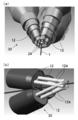
- the jet burner has a heat-resistant nozzle at a tip, the heat-resistant nozzle has a through-hole through which the molten metal or the metal wire is passed, and passes through the through-hole.
- the flame jet may be provided so as to be able to be ejected to the molten metal or the metal wire.
- metal powder can be obtained with one jet burner.
- the heat-resistant nozzle may divide the frame jet into a plurality of nozzles, and inject the flame jet into the molten metal or metal wire from positions that are rotationally symmetric with respect to the molten metal or metal wire passing through the through hole.
- the heat-resistant nozzle may be made of any material as long as it is heat-resistant, such as carbon or water-cooled copper.
- the present invention it is possible to provide a metal powder manufacturing method and a metal powder manufacturing apparatus capable of reducing the size of the apparatus, reducing the cost, and obtaining a spherical metal powder.
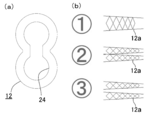
- FIG. 6A is a front view showing an injection port of the metal powder manufacturing apparatus shown in FIG. 5, and FIG. 6B is a side view showing the shape of an injected frame jet.
- A The expanded side view which shows the injection state of the flame jet of the manufacturing apparatus of the metal powder shown to Fig.1 (a),
- B The molten metal of the manufacturing apparatus of the metal powder shown to Fig.1 (a) was used.
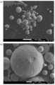
- C obtained from an Fe—Si—B-based molten metal by the metal powder manufacturing apparatus shown in FIG. 1 (a), showing the state at the time of atomization.
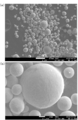
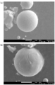
- FIG. 3 is an electron micrograph of (a) 200 times magnification and (b) 1200 times magnification of a metal powder obtained from a metal wire made of SUS420 alloy by the metal powder manufacturing apparatus shown in FIG. 2.
- a metal powder production apparatus shown in FIG. 1 (a) a metal powder production apparatus shown in FIG. 1
- a metal powder production apparatus shown in FIG. 4 (c) FIG. It is a graph which shows the particle size distribution of the metal powder manufactured by injecting a frame jet by the metal powder manufacturing apparatus shown in FIG.
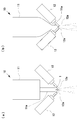
- the metal powder manufacturing apparatus 10 includes a supply unit 11 and a plurality of jet burners 12.
- the free fall type shown in FIG. 1A will be mainly described.
- the supply means 11 is composed of a container for storing molten metal.
- the supply means 11 has a pouring nozzle 11a communicating with the inside at the center of the bottom surface.
- the supply means 11 is configured to allow the molten metal stored therein to flow downward from the pouring nozzle 11a.
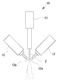
- the plurality of jet burners 12 can inject the frame jet 12a at a speed faster than the speed of sound.
- Each jet burner 12 is arranged below the supply means 11 so that the frame jet 12a can be jetted obliquely downward.
- Each jet burner 12 is provided so as to be injected obliquely at the same angle to the downstream 1 from a rotationally symmetric position with respect to the downstream 1 of the molten metal from the pouring nozzle 11a. Thereby, each jet burner 12 concentrates and jets the flame jet 12a at one point of the downstream 1.
- the jet burner 12 is a small-sized jet burner manufactured by HARD INDUSTRY CO., LTD. Capable of injecting the frame jet 12a at a speed higher than the speed of sound.
- the jet burner 12 is composed of three units, and is disposed at the same distance from the downstream 1 with a central angle of 120 degrees with respect to the downstream 1 of the molten metal as a central axis. Injection is performed at an angle of 45 degrees.
- each jet burner 12 injects the flame jet 12a with the same pressure and speed.
- the metal powder production apparatus 10 can suitably carry out the metal powder production method of the first embodiment of the present invention.
- the metal powder manufacturing apparatus 10 can obtain metal powder using the principle of the atomizing method.
- the molten metal can be pulverized by injecting a high-temperature flame jet 12a onto the downstream 1 of the molten metal.
- the flame jet 12a is hotter than the high pressure water of the water atomization method or the high pressure gas of the gas atomization method, the flow velocity of the sprayed fluid can be increased as compared with the water atomization method or the gas atomization method.
- it since it is high temperature, it can atomize, without cooling a molten metal, and it is not necessary to make the temperature of a molten metal higher than necessary.
- the temperature of the molten metal can be set lower by about 50 to 100 ° C. than the conventional water atomization method or gas atomization method. For this reason, the molten metal can be finely pulverized under conditions that make it more amorphous.
- the molten metal thus pulverized can be vitrified by being statically cooled while falling or scattering in the atmosphere, and a fine metal powder can be easily obtained.
- a finer metal powder can be obtained as compared with the water atomization method and the gas atomization method.
- each jet burner 12 injects the flame jet 12a at a speed higher than the sound speed
- the metal powder manufacturing apparatus 10 can finely pulverize the molten metal by the shock wave generated by the flame jet 12a.
- each jet burner 12 concentrates on one point of the downstream 1 at the same angle from a rotationally symmetrical position with respect to the downstream 1 of the molten metal, a plurality of frame jets are injected.
- the molten metal can be pulverized more finely, and a finer metal powder can be obtained.
- the obtained metal powder can be easily recovered by providing a container or a chamber below the supply means 11 so as to cover the periphery and the lower part of each frame jet 12a.
- the metal powder manufacturing apparatus 10 is a relatively inexpensive and small jet compared to a high pressure pump used in the water atomizing method, a high pressure gas manufacturing facility used in the gas atomizing method, a plasma torch used in the plasma atomizing method, and the like.
- the burner 12 can be used, the apparatus can be miniaturized, and costs such as equipment costs and material costs can be reduced.
- the metal powder production apparatus 10 may be a confined type as shown in FIG.
- the confined type not only the same effect as the free fall type can be obtained, but also the molten metal can be supplied directly to the atomizing zone, so that the kinetic energy of the flame jet 12a of each jet burner 12 can be efficiently reduced. Atomization can be performed.
- the conventional gas atomization or the like has a problem that the pouring nozzle 11a is cooled by the injection gas or the like, the molten metal is solidified, and the pouring nozzle 11a is easily blocked.
- the metal powder manufacturing apparatus 10 shown in FIG. 1 (b) since the high-temperature flame jet 12a is injected from each jet burner 12, the pouring nozzle 11a is not cooled, and solidification of molten metal or pouring is performed. It is possible to prevent the nozzle 11a from being blocked.
- the metal powder manufacturing apparatus 10 is provided such that the supply means 11 can continuously supply the metal wire 2 downward, and each jet burner 12 is connected to the metal wire 2. You may provide so that the flame jet 12a may be injected. In this case, the molten metal can be pulverized while the metal wire 2 is melted by injecting the high-temperature frame jet 12 a onto the metal wire 2.
- the material of the metal wire 2 is, for example, stainless steel or SUS420 alloy.
- the metal powder manufacturing apparatus 10 includes a single jet burner 12 having a heat-resistant nozzle at the tip, the heat-resistant nozzle having a through-hole through which molten metal or metal wire is passed, and a flame jet inside. 12a may be divided into a plurality of portions, and the molten metal or metal wire may be sprayed at the same angle from a rotationally symmetric position with respect to the molten metal or metal wire passing through the through hole. In this case, metal powder can be obtained with one jet burner 12.
- the heat-resistant nozzle may be composed of a nozzle used in a water atomizing method or a gas atomizing method formed of a heat-resistant material such as carbon or water-cooled copper.
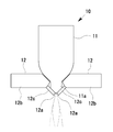
- the metal powder manufacturing apparatus 10 is configured so that the jet direction of the frame jet 12 a forms a predetermined angle with respect to the length direction of the main body 12 b of the jet burner 12.
- the injection nozzle 12c may be bent.
- the injection nozzle 12c and the pouring nozzle 11a of the supply means 11 can be easily brought close to each other. This is particularly effective when the metal powder manufacturing apparatus 10 is a confined type.
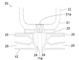
- FIG. 4 shows a metal powder production apparatus and a metal powder production method according to the second embodiment of the present invention.
- the metal powder manufacturing apparatus 20 is a confined type, and has a supply means 11 and a jet burner 12.
- the same components as those in the metal powder manufacturing apparatus 10 according to the first embodiment of the present invention are denoted by the same reference numerals, and redundant description is omitted.
- the supply means 11 has a container 21 for storing molten metal, and has a supply port 21 a communicating with the outside at the center of the bottom of the container 21. Moreover, the supply means 11 has the hot_water
- the pouring nozzle 11a has a tapered shape in which the outer shape of the tip gradually narrows downward.
- the supply means 11 can supply the molten metal stored in the container 21 from the pouring nozzle 11a.
- the jet burner 12 has one combustion chamber (not shown) and an annular injection port 24 for injecting a flame jet.
- the jet burner 12 is attached to the lower part of the container 21 of the supply means 11 so that the pouring nozzle 11 a is disposed inside the injection port 24.
- the jet burner 12 is formed so that the injection port 24 follows the tapered shape of the tip of the pouring nozzle 11a.
- the jet burner 12 is configured to be able to inject a frame jet without any gap along the circumference of the injection port 24 from the injection port 24 toward the front inner side.
- the jet burner 12 is capable of injecting a flame jet from a periphery of the molten metal supplied from the pouring nozzle 11a so as to be concentrated at one location of the molten metal so as to be oblique to the flow direction of the molten metal. It has become.
- the jet burner 12 is configured such that the flame jet can collide with the molten metal with almost uniform jet pressure without any gap along the outer periphery of the molten metal supplied from the pouring nozzle 11a.
- the jet burner 12 has a water cooling part 25 for circulating the water around the injection port 24 to cool the injection port 24.
- the jet burner 12 can eject the frame jet at a speed higher than the speed of sound.
- the jet burner 12 injects the molten metal supplied downward from the pouring nozzle 11a at an angle of about 40 degrees obliquely from above.
- the metal powder manufacturing method according to the second embodiment of the present invention is preferably implemented by the metal powder manufacturing apparatus 20.
- the flame jet injected from the periphery of the molten metal is substantially uniform with no gap along the outer periphery of the molten metal. Since it collides with the molten metal with pressure, it is possible to prevent the molten metal from scattering so as to escape from the frame jet at the collision position. For this reason, uniform atomization with respect to a molten metal is possible, and a fine and uniform spherical metal powder can be obtained. In addition, the production efficiency of the metal powder can be increased. In a specific example, the diameter of the manufactured metal powder was about 5 ⁇ m.
- the metal powder manufacturing apparatus 20 and the metal powder manufacturing method of the second embodiment of the present invention only one jet burner 12 and one combustion chamber are required, so that the apparatus can be further downsized. The manufacturing cost can be further reduced.
- the metal powder manufacturing apparatus 20 and the metal powder manufacturing method according to the second embodiment of the present invention may inject a high-temperature frame jet onto the metal wire instead of the molten metal.
- the metal powder manufacturing apparatus 30 includes a supply unit 11 and a jet burner 12.
- the same components as those of the metal powder manufacturing apparatus 10 according to the first embodiment of the present invention and the metal powder manufacturing apparatus 20 according to the second embodiment of the present invention are denoted by the same reference numerals. In addition, overlapping explanation is omitted.
- the metal powder manufacturing apparatus 30 includes three jet burners 12 each having an elongated injection port 24 for injecting the frame jet 12a.
- Each jet burner 12 is arranged so that the major axis direction of the injection port 24 is along the outer periphery of the drooping downstream 1 of the molten metal.
- Each jet burner 12 is provided so as to be able to inject the frame jet 12a at the same pressure and speed so as to collide with the downstream 1 from the rotationally symmetrical position with respect to the downstream 1 at the same angle.
- the injection port 24 has a gourd shape in which two circles are connected. Further, each jet burner 12 is disposed at the same distance from the downstream 1 with a central angle of 120 degrees with respect to the downstream 1 of the molten metal as a central axis. It is designed to spray at an angle of degrees.
- the metal powder production method according to the third embodiment of the present invention is preferably implemented by the metal powder production apparatus 30.
- the metal powder manufacturing apparatus 30 and the metal powder manufacturing method according to the third embodiment of the present invention as shown in FIG. 6 (b), uses a flame jet 12a injected from the injection port 24 of the jet burner 12, It can be spread in a planar shape along the major axis direction of the injection port 24 or can be dispersed in a plurality. For this reason, by injecting flame jets 12a from the jet burners 12 so as to surround the downstream 1 of the molten metal, there is no gap along the outer periphery of the downstream 1 of the molten metal, and the molten metal with a substantially uniform jet pressure. It can be made to collide with the downstream 1 of this.
- the metal powder manufacturing apparatus 30 and the metal powder manufacturing method according to the third embodiment of the present invention may inject the high-temperature frame jet 12a onto the metal wire instead of the molten metal.
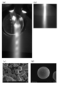
- FIG. 7A shows a state when the frame jet 12a is injected by the metal powder manufacturing apparatus 10 shown in FIG. As shown in FIG. 7A, it can be confirmed that a plurality of frame jets converges to one.
- a fine spherical Fe 75 Si 10 B 15 amorphous powder is obtained by injecting a flame jet 12a onto an Fe—Si—B based molten metal. It was.
- FIGS. 7B to 7D show the state in the vicinity of the injection position of the frame jet 12a and the electron micrographs of the obtained powder.
- a fine spherical metal powder was obtained by spraying the frame jet 12a onto the metal wire 2 made of stainless steel SUS420 using the metal powder manufacturing apparatus 10 shown in FIG. An electron micrograph of the obtained metal powder is shown in FIG.
- a fine spherical metal powder is obtained by injecting the frame jet 12a onto the metal wire 2 of the TIG welding rod TGS50 (manufactured by Kobe Steel). It was. An electron micrograph of the obtained metal powder is shown in FIG.
- a fine spherical metal powder was obtained by spraying the frame jet 12a onto the metal wire 2 made of SUS420 alloy using the metal powder manufacturing apparatus 10 shown in FIG. An electron micrograph of the obtained metal powder is shown in FIG.
- the particle size distribution of the metal powder produced by each apparatus is shown in FIG.
- the combustion parameters per jet burner 12 are 700 L / min for the air amount and 130 mL / min for the fuel (kerosene).
- the combustion parameters in the metal powder production apparatus 20 shown in FIG. 4 are an air amount of 3000 L / min and a fuel (kerosene) of 550 mL / min.
- the combustion parameters of the Laval nozzle type are 3000 L / min for the air amount and 550 mL / min for the fuel (kerosene).
- the metal powder produced by the metal powder production apparatus 10 shown in FIG. 1A and the metal powder production apparatus 20 shown in FIG. The largest number was 40 to 70 ⁇ m, and most was 100 ⁇ m or less. Moreover, most of the metal powders manufactured with the Laval nozzle type were those having a diameter of 50 ⁇ m or less. From these results, it was confirmed that fine powder could be obtained by injection of flame jet. Moreover, since the diameter of the metal powder to be manufactured is smaller in the Laval nozzle type, it can be said that the diameter of the metal powder to be manufactured decreases as the speed of the frame jet increases.
Landscapes
- Manufacture Of Metal Powder And Suspensions Thereof (AREA)
- Nozzles (AREA)
Abstract
Description
図1および図3は、本発明の第1の実施の形態の金属粉末の製造装置を示している。
図1に示すように、金属粉末の製造装置10は、供給手段11と複数のジェットバーナー12とを有している。なお、以下の説明では、主に、図1(a)に示すフリーフォール型について説明を行う。
図4に示すように、金属粉末の製造装置20は、コンファインド型であり、供給手段11とジェットバーナー12とを有している。
なお、以下の説明では、本発明の第1の実施の形態の金属粉末の製造装置10と同一の構成には同一の符号を付して、重複する説明を省略する。
図5および図6に示すように、金属粉末の製造装置30は、供給手段11とジェットバーナー12とを有している。
なお、以下の説明では、本発明の第1の実施の形態の金属粉末の製造装置10および本発明の第2の実施の形態の金属粉末の製造装置20と同一の構成には同一の符号を付して、重複する説明を省略する。
2 金属線材
10 金属粉末の製造装置
11 供給手段
11a 注湯ノズル
12 ジェットバーナー
12a フレームジェット
Claims (10)
- 溶融金属または金属線材に対してフレームジェットを噴射することにより金属粉末を得ることを特徴とする金属粉末の製造方法。
- 前記フレームジェットが前記溶融金属または前記金属線材の外周に沿って隙間なく、ほぼ均等なジェット圧で前記溶融金属または前記金属線材に衝突するよう、前記溶融金属または前記金属線材の周囲から前記フレームジェットを噴射することを特徴とする請求項1記載の金属粉末の製造方法。
- 前記フレームジェットを噴射するための円環状の噴射口を有し、前記噴射口から噴射される前記フレームジェットの内側に前記溶融金属または前記金属線材を配置して、前記フレームジェットを噴射することを特徴とする請求項1または2記載の金属粉末の製造方法。
- 複数のフレームジェットを、前記溶融金属または前記金属線材に対して互いに回転対称の位置から、前記溶融金属または前記金属線材に噴射することを特徴とする請求項1または2記載の金属粉末の製造方法。
- 溶融金属または金属線材を供給する供給手段と、
前記供給手段により供給される前記溶融金属または前記金属線材に対してフレームジェットを噴射するジェットバーナーとを、
有することを特徴とする金属粉末の製造装置。 - 前記ジェットバーナーは、前記フレームジェットが前記溶融金属または前記金属線材の外周に沿って隙間なく、ほぼ均等なジェット圧で前記溶融金属または前記金属線材に衝突するよう、前記溶融金属または前記金属線材の周囲から前記フレームジェットを噴射することを特徴とする請求項5記載の金属粉末の製造装置。
- 前記ジェットバーナーは、前記フレームジェットを噴射するための円環状の噴射口を有し、前記噴射口から噴射される前記フレームジェットの内側に、前記溶融金属または前記金属線材が配置されるよう設けられていることを特徴とする請求項5または6記載の金属粉末の製造装置。
- 前記ジェットバーナーは複数から成り、前記溶融金属または前記金属線材に対して互いに回転対称の位置から、前記溶融金属または前記金属線材に噴射するよう設けられていることを特徴とする請求項5または6記載の金属粉末の製造装置。
- 各ジェットバーナーは、それぞれ前記フレームジェットを噴射するための細長い形状の噴射口を有し、前記噴射口の長径方向が前記溶融金属または前記金属線材の外周に沿うよう配置されていることを特徴とする請求項8記載の金属粉末の製造装置。
- 前記ジェットバーナーは先端に耐熱ノズルを有し、前記耐熱ノズルは内部に前記溶融金属または前記金属線材を通す通孔を有し、前記通孔を通る前記溶融金属または前記金属線材に対して前記フレームジェットを噴射可能に設けられていることを特徴とする請求項5または6記載の金属粉末の製造装置。
Priority Applications (4)
| Application Number | Priority Date | Filing Date | Title |
|---|---|---|---|
| EP12786542.6A EP2711111A4 (en) | 2011-05-18 | 2012-05-18 | METHOD FOR PRODUCING A METAL POWDER AND DEVICE FOR PRODUCING A METAL POWDER |
| US14/118,446 US20140202286A1 (en) | 2011-05-18 | 2012-05-18 | Metal powder production method and metal powder production device |
| JP2013515210A JPWO2012157733A1 (ja) | 2011-05-18 | 2012-05-18 | 金属粉末の製造方法および金属粉末の製造装置 |
| CN201280022257.6A CN103635273A (zh) | 2011-05-18 | 2012-05-18 | 金属粉末的制造方法及金属粉末的制造装置 |
Applications Claiming Priority (2)
| Application Number | Priority Date | Filing Date | Title |
|---|---|---|---|
| JP2011-110904 | 2011-05-18 | ||
| JP2011110904 | 2011-05-18 |
Publications (1)
| Publication Number | Publication Date |
|---|---|
| WO2012157733A1 true WO2012157733A1 (ja) | 2012-11-22 |
Family
ID=47177047
Family Applications (1)
| Application Number | Title | Priority Date | Filing Date |
|---|---|---|---|
| PCT/JP2012/062736 Ceased WO2012157733A1 (ja) | 2011-05-18 | 2012-05-18 | 金属粉末の製造方法および金属粉末の製造装置 |
Country Status (5)
| Country | Link |
|---|---|
| US (1) | US20140202286A1 (ja) |
| EP (1) | EP2711111A4 (ja) |
| JP (1) | JPWO2012157733A1 (ja) |
| CN (1) | CN103635273A (ja) |
| WO (1) | WO2012157733A1 (ja) |
Cited By (9)
| Publication number | Priority date | Publication date | Assignee | Title |
|---|---|---|---|---|
| JP2014136807A (ja) * | 2013-01-15 | 2014-07-28 | Tohoku Techno Arch Co Ltd | 金属粉末の製造装置および金属粉末の製造方法 |
| JP2016204718A (ja) * | 2015-04-27 | 2016-12-08 | ハード工業有限会社 | 粉末製造装置 |
| JP2017155341A (ja) * | 2017-05-01 | 2017-09-07 | ハード工業有限会社 | 金属粉末の製造装置および金属粉末の製造方法 |
| JP2019214786A (ja) * | 2018-06-08 | 2019-12-19 | Dowaエレクトロニクス株式会社 | 金属粉末の製造方法および製造装置 |
| WO2020085355A1 (ja) | 2018-10-25 | 2020-04-30 | 三菱重工業株式会社 | アトマイズノズル、アトマイズ装置、金属粉末の製造方法、及び金属粉末 |
| US11059099B1 (en) | 2014-03-11 | 2021-07-13 | Tekna Plasma Systems Inc. | Process and apparatus for producing powder particles by atomization of a feed material in the form of an elongated member |
| JP2022046880A (ja) * | 2020-09-11 | 2022-03-24 | 三菱重工業株式会社 | 金属粉末製造装置及びそのガス噴射器 |
| CN114367668A (zh) * | 2022-01-14 | 2022-04-19 | 中航迈特粉冶科技(固安)有限公司 | 一种3d打印球形金属粉末处理喷嘴、方法和制造装置 |
| WO2025010890A1 (zh) * | 2023-07-07 | 2025-01-16 | 李振雍 | 一种激波雾化金属熔体的方法 |
Families Citing this family (27)
| Publication number | Priority date | Publication date | Assignee | Title |
|---|---|---|---|---|
| EP4324577A1 (en) | 2015-12-16 | 2024-02-21 | 6K Inc. | Method of producing spheroidal dehydrogenated titanium alloy particles |
| US10987735B2 (en) | 2015-12-16 | 2021-04-27 | 6K Inc. | Spheroidal titanium metallic powders with custom microstructures |
| US10247002B2 (en) * | 2016-02-03 | 2019-04-02 | General Electric Company | In situ gas turbine prevention of crack growth progression |
| US10443385B2 (en) * | 2016-02-03 | 2019-10-15 | General Electric Company | In situ gas turbine prevention of crack growth progression via laser welding |
| CN108237220B (zh) * | 2016-12-27 | 2020-01-14 | 中国科学院宁波材料技术与工程研究所 | 一种复合粉末及其制备方法和应用 |
| CN111050959B (zh) * | 2017-09-07 | 2022-12-16 | 哈都工业有限会社 | 金属粉末制造装置以及金属粉末的制造方法 |
| EP3710180A4 (en) * | 2017-11-14 | 2021-03-31 | Pyrogenesis Canada Inc. | METHOD AND DEVICE FOR THE PRODUCTION OF FINE SPHERICAL POWDERS FROM COARSE AND ANGLE POWDER MATERIAL |
| JP7231159B2 (ja) * | 2018-02-19 | 2023-03-01 | ハード工業有限会社 | 金属粉末製造装置、及び金属粉末の製造方法 |
| AU2019239776A1 (en) * | 2018-03-17 | 2020-10-29 | Pyrogenesis Canada Inc. | Method and apparatus for the production of high purity spherical metallic powders from a molten feedstock |
| AU2019290663B2 (en) | 2018-06-19 | 2023-05-04 | 6K Inc. | Process for producing spheroidized powder from feedstock materials |
| JP6982015B2 (ja) * | 2019-02-04 | 2021-12-17 | 三菱パワー株式会社 | 金属粉末製造装置及びそのガス噴射器 |
| EP3922380A4 (en) * | 2019-02-08 | 2022-12-21 | Mitsubishi Heavy Industries, Ltd. | METAL POWDER MANUFACTURING APPARATUS AND MELTING POWDER APPARATUS AND METAL MELTING NOZZLE THEREFOR |
| US11611130B2 (en) | 2019-04-30 | 2023-03-21 | 6K Inc. | Lithium lanthanum zirconium oxide (LLZO) powder |
| SG11202111576QA (en) | 2019-04-30 | 2021-11-29 | 6K Inc | Mechanically alloyed powder feedstock |
| AU2020400980A1 (en) | 2019-11-18 | 2022-03-31 | 6K Inc. | Unique feedstocks for spherical powders and methods of manufacturing |
| US11590568B2 (en) | 2019-12-19 | 2023-02-28 | 6K Inc. | Process for producing spheroidized powder from feedstock materials |
| EP4173060A1 (en) | 2020-06-25 | 2023-05-03 | 6K Inc. | Microcomposite alloy structure |
| EP4165957A4 (en) | 2020-09-24 | 2024-07-24 | 6K Inc. | SYSTEMS, DEVICES AND METHODS FOR STARTING PLASMA |
| WO2022094528A1 (en) | 2020-10-30 | 2022-05-05 | 6K Inc. | Systems and methods for synthesis of spheroidized metal powders |
| KR20230129011A9 (ko) | 2021-01-11 | 2024-03-21 | 6케이 인크. | 마이크로파 플라즈마 공정을 사용하여 Li-이온 캐소드 재료를 재활용하는 방법 및 시스템 |
| US12042861B2 (en) | 2021-03-31 | 2024-07-23 | 6K Inc. | Systems and methods for additive manufacturing of metal nitride ceramics |
| CN114632941B (zh) * | 2022-05-18 | 2022-09-09 | 西安欧中材料科技有限公司 | 一种提高镍基金属球形粉末成分批次稳定性的设备及方法 |
| US12261023B2 (en) | 2022-05-23 | 2025-03-25 | 6K Inc. | Microwave plasma apparatus and methods for processing materials using an interior liner |
| US12040162B2 (en) | 2022-06-09 | 2024-07-16 | 6K Inc. | Plasma apparatus and methods for processing feed material utilizing an upstream swirl module and composite gas flows |
| CN115283683B (zh) * | 2022-07-01 | 2023-08-01 | 南京尚吉增材制造研究院有限公司 | 高球形度及低氧增量钛合金粉末的制备方法及系统 |
| WO2024044498A1 (en) | 2022-08-25 | 2024-02-29 | 6K Inc. | Plasma apparatus and methods for processing feed material utilizing a powder ingress preventor (pip) |
| US12195338B2 (en) | 2022-12-15 | 2025-01-14 | 6K Inc. | Systems, methods, and device for pyrolysis of methane in a microwave plasma for hydrogen and structured carbon powder production |
Citations (9)
| Publication number | Priority date | Publication date | Assignee | Title |
|---|---|---|---|---|
| JPS60211005A (ja) * | 1984-02-29 | 1985-10-23 | ゼネラル・エレクトリツク・カンパニイ | 不安定な溶融液流を噴霧する装置および方法 |
| JPH05271719A (ja) * | 1992-03-27 | 1993-10-19 | Teikoku Piston Ring Co Ltd | 金属粉末の製造方法 |
| JPH10176206A (ja) * | 1996-12-17 | 1998-06-30 | Akihisa Inoue | 溶湯金属から金属粉末を製造する方法 |
| JPH11257615A (ja) * | 1998-03-10 | 1999-09-21 | Daioo:Kk | 球状粒子製造用バーナ |
| JP2003530679A (ja) * | 2000-04-10 | 2003-10-14 | テトロニクス リミテッド | ツイン・プラズマ・トーチ装置 |
| JP2004183049A (ja) | 2002-12-03 | 2004-07-02 | Dowa Mining Co Ltd | ガスアトマイズ法による微細金属粉末の製造方法及び微細金属粉末の製造装置 |
| JP2005139471A (ja) | 2003-11-04 | 2005-06-02 | Daido Steel Co Ltd | ガスアトマイズノズル及びこれを用いた金属の溶解噴霧装置 |
| JP2006063357A (ja) | 2004-08-24 | 2006-03-09 | Daido Steel Co Ltd | 水アトマイズ法による金属粉末の製造方法 |
| JP2006241562A (ja) * | 2005-03-07 | 2006-09-14 | Daido Steel Co Ltd | 金属溶湯の連続噴霧装置 |
Family Cites Families (15)
| Publication number | Priority date | Publication date | Assignee | Title |
|---|---|---|---|---|
| SU367898A1 (ru) * | 1968-06-25 | 1973-01-26 | Установка для получения металлических порошков распылением | |
| JPS5524974A (en) * | 1978-08-11 | 1980-02-22 | Fukuda Kinzoku Hakufun Kogyo Kk | Producing metal grain and equipment therefor |
| JPS56142803A (en) * | 1980-04-03 | 1981-11-07 | Tanaka Kikinzoku Kogyo Kk | Preparation of composite powder |
| JPS5947001B2 (ja) * | 1980-09-04 | 1984-11-16 | 住友金属工業株式会社 | 金属粉末の製造方法 |
| DE3533964C1 (de) * | 1985-09-24 | 1987-01-15 | Alfred Prof Dipl-Ing Dr-I Walz | Verfahren und Vorrichtung zum Herstellen von Feinstpulver in Kugelform |
| JPS62278208A (ja) * | 1986-05-27 | 1987-12-03 | Fukuda Metal Foil & Powder Co Ltd | 金属粉末製造用リングノズル |
| JP2580616B2 (ja) * | 1987-09-09 | 1997-02-12 | 大同特殊鋼株式会社 | 球状金属粉末の製造方法 |
| JPH01219109A (ja) * | 1988-02-26 | 1989-09-01 | Sumitomo Metal Ind Ltd | ガスアトマイズ法による微粉末の製造方法 |
| JPH0474809A (ja) * | 1990-07-16 | 1992-03-10 | Mitsubishi Materials Corp | 球状金属粒子の製造方法と装置 |
| GB9316522D0 (en) * | 1993-08-09 | 1993-09-22 | Hopkins William | Apparatus for and methods of producing a particulate spray |
| JPH08143915A (ja) * | 1994-11-28 | 1996-06-04 | Tanaka Kikinzoku Kogyo Kk | 強化白金材料用粉末及び強化白金材料の製造方法 |
| US6444009B1 (en) * | 2001-04-12 | 2002-09-03 | Nanotek Instruments, Inc. | Method for producing environmentally stable reactive alloy powders |
| RU2281812C2 (ru) * | 2004-07-13 | 2006-08-20 | Тольяттинский государственный университет | Сверхзвуковое сопло газопламенной горелки |
| JP4304221B2 (ja) * | 2007-07-23 | 2009-07-29 | 大陽日酸株式会社 | 金属超微粉の製造方法 |
| JP5859719B2 (ja) * | 2009-06-23 | 2016-02-10 | 大陽日酸株式会社 | 金属超微粉の製造方法および製造装置 |
-
2012
- 2012-05-18 EP EP12786542.6A patent/EP2711111A4/en not_active Withdrawn
- 2012-05-18 CN CN201280022257.6A patent/CN103635273A/zh active Pending
- 2012-05-18 US US14/118,446 patent/US20140202286A1/en not_active Abandoned
- 2012-05-18 JP JP2013515210A patent/JPWO2012157733A1/ja active Pending
- 2012-05-18 WO PCT/JP2012/062736 patent/WO2012157733A1/ja not_active Ceased
Patent Citations (9)
| Publication number | Priority date | Publication date | Assignee | Title |
|---|---|---|---|---|
| JPS60211005A (ja) * | 1984-02-29 | 1985-10-23 | ゼネラル・エレクトリツク・カンパニイ | 不安定な溶融液流を噴霧する装置および方法 |
| JPH05271719A (ja) * | 1992-03-27 | 1993-10-19 | Teikoku Piston Ring Co Ltd | 金属粉末の製造方法 |
| JPH10176206A (ja) * | 1996-12-17 | 1998-06-30 | Akihisa Inoue | 溶湯金属から金属粉末を製造する方法 |
| JPH11257615A (ja) * | 1998-03-10 | 1999-09-21 | Daioo:Kk | 球状粒子製造用バーナ |
| JP2003530679A (ja) * | 2000-04-10 | 2003-10-14 | テトロニクス リミテッド | ツイン・プラズマ・トーチ装置 |
| JP2004183049A (ja) | 2002-12-03 | 2004-07-02 | Dowa Mining Co Ltd | ガスアトマイズ法による微細金属粉末の製造方法及び微細金属粉末の製造装置 |
| JP2005139471A (ja) | 2003-11-04 | 2005-06-02 | Daido Steel Co Ltd | ガスアトマイズノズル及びこれを用いた金属の溶解噴霧装置 |
| JP2006063357A (ja) | 2004-08-24 | 2006-03-09 | Daido Steel Co Ltd | 水アトマイズ法による金属粉末の製造方法 |
| JP2006241562A (ja) * | 2005-03-07 | 2006-09-14 | Daido Steel Co Ltd | 金属溶湯の連続噴霧装置 |
Non-Patent Citations (3)
| Title |
|---|
| MURAKAMI, YOTARO, METHOD FOR PRODUCING HIGH-QUALITY METAL POWDER, September 2003 (2003-09-01) |
| OSAKA SCIENCE & TECHNOLOGY CENTER, 17 January 2011 (2011-01-17), Retrieved from the Internet <URL:Hwww.ostec.or.jp/nmc/TOP/nmc-news.htm> |
| See also references of EP2711111A4 |
Cited By (16)
| Publication number | Priority date | Publication date | Assignee | Title |
|---|---|---|---|---|
| JP2014136807A (ja) * | 2013-01-15 | 2014-07-28 | Tohoku Techno Arch Co Ltd | 金属粉末の製造装置および金属粉末の製造方法 |
| US11638958B2 (en) | 2014-03-11 | 2023-05-02 | Tekna Plasma Systems Inc. | Process and apparatus for producing powder particles by atomization of a feed material in the form of an elongated member |
| US11059099B1 (en) | 2014-03-11 | 2021-07-13 | Tekna Plasma Systems Inc. | Process and apparatus for producing powder particles by atomization of a feed material in the form of an elongated member |
| US11110515B2 (en) | 2014-03-11 | 2021-09-07 | Tekna Plasma Systems Inc. | Process and apparatus for producing powder particles by atomization of a feed material in the form of an elongated member |
| US11951549B2 (en) | 2014-03-11 | 2024-04-09 | Tekna Plasma Systems Inc. | Process and apparatus for producing powder particles by atomization of a feed material in the form of an elongated member |
| US11565319B2 (en) | 2014-03-11 | 2023-01-31 | Tekna Plasma Systems Inc. | Process and apparatus for producing powder particles by atomization of a feed material in the form of an elongated member |
| JP2016204718A (ja) * | 2015-04-27 | 2016-12-08 | ハード工業有限会社 | 粉末製造装置 |
| JP2017155341A (ja) * | 2017-05-01 | 2017-09-07 | ハード工業有限会社 | 金属粉末の製造装置および金属粉末の製造方法 |
| JP2019214786A (ja) * | 2018-06-08 | 2019-12-19 | Dowaエレクトロニクス株式会社 | 金属粉末の製造方法および製造装置 |
| JP7328796B2 (ja) | 2018-06-08 | 2023-08-17 | Dowaエレクトロニクス株式会社 | 金属粉末の製造方法および製造装置 |
| WO2020085355A1 (ja) | 2018-10-25 | 2020-04-30 | 三菱重工業株式会社 | アトマイズノズル、アトマイズ装置、金属粉末の製造方法、及び金属粉末 |
| US12090555B2 (en) | 2018-10-25 | 2024-09-17 | Mitsubishi Heavy Industries, Ltd. | Atomizer nozzle, atomizing device, method for producing metal powder, and metal powder |
| JP7218335B2 (ja) | 2020-09-11 | 2023-02-06 | 三菱重工業株式会社 | 金属粉末製造装置及びそのガス噴射器 |
| JP2022046880A (ja) * | 2020-09-11 | 2022-03-24 | 三菱重工業株式会社 | 金属粉末製造装置及びそのガス噴射器 |
| CN114367668A (zh) * | 2022-01-14 | 2022-04-19 | 中航迈特粉冶科技(固安)有限公司 | 一种3d打印球形金属粉末处理喷嘴、方法和制造装置 |
| WO2025010890A1 (zh) * | 2023-07-07 | 2025-01-16 | 李振雍 | 一种激波雾化金属熔体的方法 |
Also Published As
| Publication number | Publication date |
|---|---|
| US20140202286A1 (en) | 2014-07-24 |
| EP2711111A1 (en) | 2014-03-26 |
| EP2711111A4 (en) | 2015-05-20 |
| JPWO2012157733A1 (ja) | 2014-07-31 |
| CN103635273A (zh) | 2014-03-12 |
Similar Documents
| Publication | Publication Date | Title |
|---|---|---|
| WO2012157733A1 (ja) | 金属粉末の製造方法および金属粉末の製造装置 | |
| JP6178575B2 (ja) | 金属粉末の製造装置および金属粉末の製造方法 | |
| JP6205442B2 (ja) | 金属粉末製造装置 | |
| KR101512772B1 (ko) | 금속 분말을 제조하기 위한 방법 및 아토마이저 장치 | |
| JP6906631B2 (ja) | 金属粉末製造装置並びにそのガス噴射器及びるつぼ器 | |
| JP7231159B2 (ja) | 金属粉末製造装置、及び金属粉末の製造方法 | |
| CA3070371A1 (en) | Method for cost-effective production of ultrafine spherical powders at large scale using thruster-assisted plasma atomization | |
| JP6298794B2 (ja) | 粉末製造装置 | |
| CN114245762A (zh) | 分离导电液体的方法以及装置 | |
| KR101536454B1 (ko) | 분말 제조 장치 및 분말 형성 방법 | |
| JP2015000997A (ja) | 軟質磁性金属粉末製造装置 | |
| KR20180046652A (ko) | 금속 분말 제조를 위한 원추형 수분사 아토마이저 가변 노즐 | |
| JP6854008B2 (ja) | 金属粉末製造装置 | |
| CN111050959B (zh) | 金属粉末制造装置以及金属粉末的制造方法 | |
| WO2015114838A1 (ja) | 金属粉末の製造方法および金属粉末の製造装置 | |
| JP2017155341A (ja) | 金属粉末の製造装置および金属粉末の製造方法 | |
| CN102489711A (zh) | 一种制备微细金属粉末的气体雾化喷嘴 | |
| JP2017145493A (ja) | 金属粉末製造装置 | |
| CN201052487Y (zh) | 制备铜粉的二次加速超音速雾化喷嘴系统 | |
| JPH0649512A (ja) | ガス噴霧金属粉末製造装置 | |
| JP7328796B2 (ja) | 金属粉末の製造方法および製造装置 | |
| JP2019031711A (ja) | 金属粉末製造装置と金属粉末の製造方法 | |
| JP2021130865A (ja) | 金属粉末製造装置及び金属粉末製造方法 | |
| JPH08199207A (ja) | 金属粉末の製造方法およびその装置 | |
| JPH04276005A (ja) | 金属微粉末の製造方法 |
Legal Events
| Date | Code | Title | Description |
|---|---|---|---|
| 121 | Ep: the epo has been informed by wipo that ep was designated in this application |
Ref document number: 12786542 Country of ref document: EP Kind code of ref document: A1 |
|
| DPE2 | Request for preliminary examination filed before expiration of 19th month from priority date (pct application filed from 20040101) | ||
| ENP | Entry into the national phase |
Ref document number: 2013515210 Country of ref document: JP Kind code of ref document: A |
|
| NENP | Non-entry into the national phase |
Ref country code: DE |
|
| WWE | Wipo information: entry into national phase |
Ref document number: 2012786542 Country of ref document: EP |
|
| WWE | Wipo information: entry into national phase |
Ref document number: 14118446 Country of ref document: US |