WO2012157770A1 - Fil à haute tension, et procédé de production d'un fil à haute tension - Google Patents
Fil à haute tension, et procédé de production d'un fil à haute tension Download PDFInfo
- Publication number
- WO2012157770A1 WO2012157770A1 PCT/JP2012/062870 JP2012062870W WO2012157770A1 WO 2012157770 A1 WO2012157770 A1 WO 2012157770A1 JP 2012062870 W JP2012062870 W JP 2012062870W WO 2012157770 A1 WO2012157770 A1 WO 2012157770A1
- Authority
- WO
- WIPO (PCT)
- Prior art keywords
- insulator
- electric wire
- voltage electric
- conductors
- thickness
- Prior art date
- Legal status (The legal status is an assumption and is not a legal conclusion. Google has not performed a legal analysis and makes no representation as to the accuracy of the status listed.)
- Ceased
Links
Images


Classifications
-
- H—ELECTRICITY
- H01—ELECTRIC ELEMENTS
- H01B—CABLES; CONDUCTORS; INSULATORS; SELECTION OF MATERIALS FOR THEIR CONDUCTIVE, INSULATING OR DIELECTRIC PROPERTIES
- H01B7/00—Insulated conductors or cables characterised by their form
- H01B7/08—Flat or ribbon cables
-
- B—PERFORMING OPERATIONS; TRANSPORTING
- B60—VEHICLES IN GENERAL
- B60R—VEHICLES, VEHICLE FITTINGS, OR VEHICLE PARTS, NOT OTHERWISE PROVIDED FOR
- B60R16/00—Electric or fluid circuits specially adapted for vehicles and not otherwise provided for; Arrangement of elements of electric or fluid circuits specially adapted for vehicles and not otherwise provided for
- B60R16/02—Electric or fluid circuits specially adapted for vehicles and not otherwise provided for; Arrangement of elements of electric or fluid circuits specially adapted for vehicles and not otherwise provided for electric constitutive elements
- B60R16/0207—Wire harnesses
- B60R16/0215—Protecting, fastening and routing means therefor
-
- H—ELECTRICITY
- H01—ELECTRIC ELEMENTS
- H01B—CABLES; CONDUCTORS; INSULATORS; SELECTION OF MATERIALS FOR THEIR CONDUCTIVE, INSULATING OR DIELECTRIC PROPERTIES
- H01B7/00—Insulated conductors or cables characterised by their form
- H01B7/08—Flat or ribbon cables
- H01B7/0823—Parallel wires, incorporated in a flat insulating profile
-
- B—PERFORMING OPERATIONS; TRANSPORTING
- B60—VEHICLES IN GENERAL
- B60R—VEHICLES, VEHICLE FITTINGS, OR VEHICLE PARTS, NOT OTHERWISE PROVIDED FOR
- B60R16/00—Electric or fluid circuits specially adapted for vehicles and not otherwise provided for; Arrangement of elements of electric or fluid circuits specially adapted for vehicles and not otherwise provided for
- B60R16/02—Electric or fluid circuits specially adapted for vehicles and not otherwise provided for; Arrangement of elements of electric or fluid circuits specially adapted for vehicles and not otherwise provided for electric constitutive elements
-
- H—ELECTRICITY
- H01—ELECTRIC ELEMENTS
- H01B—CABLES; CONDUCTORS; INSULATORS; SELECTION OF MATERIALS FOR THEIR CONDUCTIVE, INSULATING OR DIELECTRIC PROPERTIES
- H01B13/00—Apparatus or processes specially adapted for manufacturing conductors or cables
- H01B13/06—Insulating conductors or cables
- H01B13/14—Insulating conductors or cables by extrusion
- H01B13/145—Pretreatment or after-treatment
-
- H—ELECTRICITY
- H01—ELECTRIC ELEMENTS
- H01B—CABLES; CONDUCTORS; INSULATORS; SELECTION OF MATERIALS FOR THEIR CONDUCTIVE, INSULATING OR DIELECTRIC PROPERTIES
- H01B7/00—Insulated conductors or cables characterised by their form
-
- H—ELECTRICITY
- H01—ELECTRIC ELEMENTS
- H01B—CABLES; CONDUCTORS; INSULATORS; SELECTION OF MATERIALS FOR THEIR CONDUCTIVE, INSULATING OR DIELECTRIC PROPERTIES
- H01B7/00—Insulated conductors or cables characterised by their form
- H01B7/02—Disposition of insulation
- H01B7/0275—Disposition of insulation comprising one or more extruded layers of insulation
-
- H—ELECTRICITY
- H01—ELECTRIC ELEMENTS
- H01B—CABLES; CONDUCTORS; INSULATORS; SELECTION OF MATERIALS FOR THEIR CONDUCTIVE, INSULATING OR DIELECTRIC PROPERTIES
- H01B7/00—Insulated conductors or cables characterised by their form
- H01B7/08—Flat or ribbon cables
- H01B7/0807—Twin conductor or cable
Definitions
- the present invention relates to a high-voltage electric wire including a plurality of conductors and an insulator that collectively covers the conductor, and a method for manufacturing the high-voltage electric wire.
- Hybrid vehicles and electric vehicles have attracted attention as eco-cars.
- the penetration rate of hybrid vehicles and electric vehicles is increasing.
- Hybrid vehicles and electric vehicles are equipped with a motor as a power source.
- a wire harness that can withstand a high voltage includes a plurality of high-voltage electric wires that are conductive paths.
- pressure is called a high voltage electric wire.
- the wire harness disclosed in Patent Document 1 below employs a structure in which a plurality of high-voltage wires are arranged in a horizontal row. With this structure, the height of the wire harness is reduced, and even if the wire harness is assembled under the floor of the vehicle, the wire harness is positioned away from the ground. As a result, the wire harness can be prevented from being broken or damaged.
- the wire harness disclosed in Patent Document 1 includes a plurality of high-voltage electric wires arranged in a horizontal row, when the wire harness is routed in the vehicle, the length in the vehicle height direction is minimized. However, the length in the vehicle width direction becomes longer. Therefore, the inventor of the present application assumes that there is a demand for space saving in the future, and thinks that it is necessary to examine a structure that can meet this demand.
- wire harness Although not limited to the wire harness, for example, in order to increase the travel distance of the vehicle, it is required to reduce the weight of vehicle components mounted on the vehicle.
- the present invention has been made in view of the above circumstances, and an object of the present invention is to provide a high-voltage electric wire that can save space and can be reduced in weight, and a manufacturing method thereof.
- the high-voltage electric wire according to the present invention made to solve the above-described problem includes a plurality of conductors and an insulator that covers the plurality of conductors in a row and covers the conductors adjacent to each other.
- the thickness of the insulator at the point where the interval between the conductors becomes the narrowest among the adjacent portions sandwiched between the two is not more than the thickness of the non-adjacent portions.
- the insulator has a thickness of a point where the thinnest point in the adjacent portion is 0.25 mm or more.
- the manufacturing method of the high-voltage electric wire of the present invention made to solve the above-mentioned problem is that the adjacent portions sandwiched between the adjacent conductors when the insulator is collectively covered by extrusion with respect to a plurality of aligned conductors
- the insulator is extrusion-coated so that the thickness of the insulator at the point where the distance between the conductors becomes the narrowest is not more than the thickness of the non-adjacent portion.
- the conductor is preheated and then the insulator is extrusion coated.
- the high-voltage electric wire of the present invention there is an effect that space saving and weight reduction can be achieved as compared with the conventional one. Specifically, when comparing a plurality of conventional high-voltage wires with an insulator provided on the conductor and the high-voltage wires of the present invention, when conventional high-voltage wires are arranged one by one, Since the insulator of each high voltage electric wire is interposed between the conductors of each high voltage electric wire, the conductors are separated by two insulators.
- the high-voltage electric wire of the present invention is formed by collectively covering an insulator with a plurality of conductors, and the insulator has the largest distance between the conductors in the adjacent portions of the adjacent conductors.
- the high-voltage electric wire according to the present invention can be made narrower than the case where a plurality of conventional high-voltage electric wires are arranged, and the space can be saved.
- the high-voltage electric wire of the present invention has an effect that the thickness of the insulator between the conductors can be made thinner than before, so that at least the weight can be reduced by this thinning.
- the method for producing a high-voltage electric wire of the present invention there is an effect that it is possible to provide a method for producing a high-voltage electric wire that can save space and weight as compared with the conventional method.
- the fluidity of the insulator pushed out to the conductor is improved, so that the insulator thickness between adjacent conductors can be easily reduced. There is an effect that can be done.
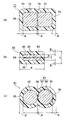
- FIG. 1 (a) to 1 (c) are diagrams relating to a high-voltage electric wire according to the present invention.
- FIG. 1 (a) is a schematic diagram of a vehicle
- FIGS. 1 (b) and 1 (c) are high-voltage electric wires.
- It is sectional drawing. 2 (a) to 2 (c) are diagrams relating to the comparison of the widths of the high-voltage electric wires
- FIG. 2 (a) is a cross-sectional view of the high-voltage electric wires in FIG. 1 (b)
- FIG. 1C is a cross-sectional view of a high-voltage electric wire
- FIG. 2C is a cross-sectional view of a conventional high-voltage electric wire.
- FIG. 3 (a) to 3 (c) are diagrams relating to a method of manufacturing a high-voltage electric wire
- FIG. 3 (a) is a schematic view of the entire manufacturing process
- FIG. 3 (b) is a cross-sectional view relating to a conductor delivery state.
- FIG. 3C is a cross-sectional view showing a state in which an insulator is extrusion-coated.
- 4 (a) and 4 (b) are diagrams of a wire harness including a high-voltage electric wire
- FIG. 4 (a) is a cross-sectional view of the wire harness in a state in which a shield member and a sheath are integrally formed with the high-voltage electric wire.
- FIG. 5 (a) to 5 (c) are diagrams relating to another example of the high-voltage electric wire, and FIG. 5 (a) is a cross-sectional view of the high-voltage electric wire having two conductors, FIG. 5 (b) and FIG. 5 (c) is a cross-sectional view of a high-voltage electric wire having three conductors.
- 6 (a) to 6 (c) are diagrams relating to another example of the high-voltage electric wire, and FIG. 6 (a) is a cross-sectional view of the high-voltage electric wire using a bar-shaped rectangular conductor as the conductor, FIG. 6 (b).
- FIG. 6C is a cross-sectional view of a high-voltage electric wire in which the conductor is a flat rectangular conductor, and FIG.
- the high-voltage electric wire is formed by coating an insulator on a plurality of arranged conductors at the same time, and among the adjacent portions sandwiched between adjacent conductors, the thickness of the insulator at the point where the distance between the conductors is the narrowest Is less than or equal to the thickness of the insulator in the part not adjacent to each other.
- FIG. 1 (a) to 1 (c) are diagrams relating to a high-voltage electric wire according to the present invention
- FIG. 1 (a) is a schematic view of a vehicle
- FIGS. 1 (b) and 1 (c) are cross-sectional views of the high-voltage electric wire.
- FIG. 2 (a) to 2 (c) are diagrams relating to the comparison of the widths of the high-voltage electric wires
- FIGS. 3 (a) to 3 (c) are diagrams relating to the manufacturing method of the high-voltage electric wires
- 4 (c) is a diagram of a wire harness including a high-voltage electric wire
- FIGS. 5 (a) to 5 (c) and FIGS. 6 (a) to 6 (c) are diagrams relating to other examples of the high-voltage electric wire. is there.
- reference numeral 1 indicates a hybrid vehicle.
- the hybrid vehicle 1 is a vehicle that mixes and drives two powers of an engine 2 and a motor unit 3, and the motor unit 3 is supplied with electric power from a battery 5 (battery pack) via an inverter unit 4. It is like that.
- the engine 2, the motor unit 3, and the inverter unit 4 are mounted in the engine room 6 where the front wheels and the like are located in the present embodiment.
- the battery 5 is mounted on the rear part 7 of the vehicle having rear wheels and the like.
- the battery 5 may be mounted in an automobile room existing behind the engine room 6.
- the motor unit 3 and the inverter unit 4 are connected by a wire harness 8.
- the battery 5 and the inverter unit 4 are also connected by a wire harness 9.
- the wire harnesses 8 and 9 are configured for high pressure.
- the wire harness 8 is sometimes called a motor cable.
- the wire harness 8 is shorter than the wire harness 9.
- the intermediate portion 10 of the wire harness 9 is routed under the vehicle floor 11.
- the wire harness 9 may be routed on the vehicle interior side.
- the vehicle underfloor 11 is a portion that becomes a so-called panel member on the ground side of the vehicle body.
- a through hole (not shown) is formed through the predetermined position.
- the through hole portion is provided with a waterproof structure (not shown) for waterproofing with the wire harness 9.
- the wire harness 9 and the battery 5 are connected via a junction block 12 provided in the battery 5.
- a rear end 13 of the wire harness 9 is connected to the junction block 12.
- the rear end 13 side of the wire harness 9 is routed on the floor which is the automobile interior side.
- the front end 14 side of the wire harness 9 is also routed.
- the front end 14 side of the wire harness 9 is connected to the inverter unit 4.
- the motor unit 3 includes a motor and a generator.
- the inverter unit 4 includes an inverter and a converter in its configuration.
- the motor unit 3 is formed as a motor assembly including a shield case.
- the inverter unit 4 is also formed as an inverter assembly including a shield case.
- the battery 5 is of Ni-MH type or Li-ion type and is modularized. It is assumed that a power storage device such as a capacitor can be used.
- the battery 5 is not particularly limited as long as it can be used for the hybrid vehicle 1 and the electric vehicle.
- the wire harness 9 that connects the inverter unit 4 and the battery 5 includes the high-voltage wire 21 according to the present invention or the high-voltage wire 21 ′ according to the present invention. ing. Both the high-voltage electric wire 21 and the high-voltage electric wire 21 ′ are reduced in space and weight as compared with the conventional example.
- the high-voltage electric wire 21 and the high-voltage electric wire 21 ′ include two conductors 22 and an insulator 23 that covers the two conductors 22 side by side. It is comprised including.
- the two conductors 22 have a circular cross section and are arranged so that their longitudinal directions are parallel to each other.
- the number of the conductors 22 is two in the case of the wire harness 9, it is not limited to this number.
- the wire harness 8 that connects the motor unit 3 and the inverter unit 4 there are three as will be described later.
- the conductors 22 are arranged so that their longitudinal directions are parallel to each other and their axes are located on the same plane.
- the high-voltage electric wire 21 and the high-voltage electric wire 21 ′ are bent so as to have the same flexibility as before, or to be rigid enough to maintain the shape along the wiring path of the wire harness 9, that is, from a straight state. When applied, it is formed so as to have rigidity capable of maintaining the bent shape without returning to the original shape.
- the conductor 22 is a stranded wire conductor having a circular cross section formed by twisting copper, copper alloy, aluminum, or an aluminum alloy strand.
- the material of the conductor 22 is not limited to this, and a material used as a conductor of an electric wire can be applied. Other examples will be described later. In order to make the conductor 22 inexpensive and light, it is effective to use aluminum or an aluminum alloy among the above materials.
- the insulator 23 covers and insulates and protects the conductor 22, and is formed by covering the two conductors 22 arranged as described above.
- the insulator 23 is formed in a substantially glasses shape in cross section.
- a thermoplastic resin material such as polyethylene, polypropylene, polyvinyl chloride, or a fluororesin may be used.
- the material of the insulator 23 is not limited to this, and a material used as an insulator of an electric wire can be applied. In this embodiment, cross-linked polyethylene is used.
- the insulator 23 is a portion sandwiched between adjacent conductors 22, in other words, a portion where the conductors 22 are adjacent to each other, “an adjacent portion 24”, and a portion other than the adjacent portion 24, And a non-matching portion 25 ".
- the adjacent portions 24 are set so that the lower limit value of the thickness A at the thinnest point in this portion is 0.25 mm.
- the “thinnest point” is also “a point at which the distance between the conductors 22 is the narrowest”.
- an insulator 23 is formed so that the thickness A of the adjacent portion 24 is 0.25 mm which is the lower limit value.
- the lower limit of 0.25 mm is set to ensure 5 kV as the withstand voltage of the electric wire when the high voltage electric wire 21 is used in a high voltage circuit.
- the adjacent portion 24 is a portion that does not require consideration of wear resistance as an electric wire.
- the thickness A of the thinnest point in the adjacent portion 24 if the thickness is smaller than the thickness G of the conventional example (see FIG. 2C, which will be described later) (A ⁇ G), space saving is achieved. Is possible, and this may be the upper limit. However, in the present embodiment, in order to make it better, the same thickness B as that of the non-adjacent portion 25 is set as the upper limit for the thickness A of the thinnest point in the adjacent portion 24. The thickness B of the non-adjacent portions 25 is set to be the same as the thickness H (see FIG. 2C, which will be described later) of the insulator 103 of the conventional example.
- the insulator 23 is formed so that the thickness A of the thinnest point in the adjacent portion 24 becomes the above upper limit value.
- the high-voltage wire 21 Since the insulator 23 is formed so that the thickness A of the thinnest point in the adjacent portion 24 is the lower limit value of 0.25 mm, the high-voltage wire 21 has a narrow width C as the high-voltage wire 21. Yes. Note that the direction of the width C coincides with the vehicle width direction. Moreover, since the insulator 23 is formed so that the thickness A of the thinnest point in the adjacent portion 24 becomes the above-mentioned upper limit value, the high-voltage wire 21 ′ has a width D as the high-voltage wire 21 ′. Although slightly wider than the high-voltage electric wire 21, it is sufficiently narrow.
- the high-voltage electric wire 21 and the high-voltage electric wire 21 ′ are assumed to have the same dimensions as the conventional example with respect to the dimension E in the vehicle height direction. Therefore, even if the middle part 10 of the wire harness 9 is routed under the vehicle floor 11, the dimension is such that the distance from the ground can be earned.
- a conventional high-voltage electric wire 101 shown in FIG. 2C includes a conductor 102 and an insulator 103.
- the insulator 103 is formed so as to cover the entire circumference of the conductor 102 with a uniform thickness H. Setting the insulator 103 to a uniform thickness H is important for ensuring the wear resistance of the electric wire. When two such high voltage electric wires 101 are arranged so as to be in contact with each other, adjacent portions of the conductors 102 have a thickness G (G is twice H).
- the high-voltage electric wire 101 of the conventional example is a copper stranded wire electric wire having a wire size (cross-sectional area) of 15 mm 2 and a finished outer diameter of 7.5 mm
- Width F finished outer diameter in the major axis direction
- the high-voltage electric wire 21 and the high-voltage electric wire 21 ′ are manufactured as follows, for example. That is, as shown in FIG. 3A, the conductor 22 is individually fed out from the two drums 26, and thereafter, the insulator 23 is extrusion coated with the insulator molding die 27. In the insulator forming die 27, the interval J between the conductors 22 is maintained as shown in FIG. This interval J is the same as the thickness A of the thinnest point in the adjacent portion 24.
- the insulator 23 is extrusion coated on the conductor 22 as shown in FIG. In this embodiment, it is assumed that the conductor 22 is preheated before the insulator 23 is extrusion coated. This preheating has an advantage of improving the fluidity of the insulator 23.
- the wire harness 9 is configured as follows, for example. That is, as shown in FIG. 4A, the above-described configuration of the high-voltage electric wire 21, the conductive shield member 28 made of braid or metal foil, and the insulating sheath 29 that is extrusion-coated on the outside of the shield member 28, It is configured with.
- the wire harness 9 is manufactured in a cable shape in which a shield member 28 and a sheath 29 are integrated with the high-voltage electric wire 21.
- the material of the sheath 29 is preferably a resin material having various characteristics such as wear resistance, heat resistance, weather resistance, impact resistance, and extrusion moldability. In this case, it becomes possible to make the wire harness 9 without an exterior member.
- the resin material that enables the exterior member to be omitted may be applied to the insulator 23.
- the wire harness 9 as shown in FIG. 4B includes a high-voltage electric wire 21, a shield member 30 that accommodates the high-voltage electric wire 21 over its entire length, and a cylindrical exterior member 31 that accommodates these members.
- the shield member 30 is formed in a cylindrical shape by braiding or metal foil.
- the exterior member 31 is a flat corrugated tube, a protector, or the like.
- the wire harness 9 may include a metal protection pipe having a shielding function, and may have a configuration and a structure in which the high voltage electric wire 21 is accommodated in the metal protection pipe.
- high-voltage electric wire 21 may be replaced with a high-voltage electric wire 21 ', or may be replaced with a high-voltage electric wire as a modified example as shown in FIGS.
- modified examples will be described.
- the high-voltage electric wire 41 is configured to include two conductors 42 and an insulator 43 that covers the two conductors 42 side by side.
- the conductor 42 is formed to have the same conductor structure as the conductor 22 (see FIG. 1B) or a round single core.
- the insulator 43 is not formed in a cross-sectional glasses shape (a cross-sectional shape arranged so that two circles partially overlap each other), but here is formed in an oval shape.
- the insulator 43 is formed so that the thickness A of the thinnest point in the adjacent portion 44 is a lower limit value of 0.25 mm.
- the insulator 43 is formed such that the thickness B of the non-adjacent portion 45 is the same as the thickness B of the non-adjacent portion 25 described with reference to FIG.
- the high-voltage electric wire 51 includes three conductors 52 and an insulator 53 that covers the three conductors 52 side by side.
- the conductor 52 is formed in a conductor structure having a single round core, similar to the conductor 22 described with reference to FIG.
- the insulator 53 is formed in a substantially glasses shape in cross section.
- the insulator 53 is formed such that the thickness A of the thinnest point in the adjacent portion 54 is a lower limit value of 0.25 mm.
- the insulator 53 is formed such that the thickness B of the non-adjacent portion 55 is the same as the thickness B of the non-adjacent portion 25 described with reference to FIG.
- the high voltage electric wire 51 is preferably used for the wire harness 8 (see FIG. 1A) connecting the motor unit 3 and the inverter unit 4.
- the high-voltage electric wire 61 includes three conductors 62 and an insulator 63 that covers the three conductors 62 side by side.
- the conductor 62 is formed in a conductor structure having a single round core, similar to the conductor 22 described with reference to FIG.
- the insulator 63 does not have a substantially glasses shape in cross section, but is formed in an oval shape here.
- the insulator 63 is formed so that the thickness A of the thinnest point in the adjacent portion 64 is a lower limit value of 0.25 mm.
- the insulator 63 is formed such that the thickness B of the non-adjacent portion 65 is the same as the thickness B of the non-adjacent portion 25 described with reference to FIG.
- the high voltage electric wire 61 is preferably used for the wire harness 8 (see FIG. 1A) that connects the motor unit 3 and the inverter unit 4.
- the high voltage electric wire 71 includes two conductors 72 and an insulator 73 that covers the two conductors 72 side by side.
- the conductor 72 is formed to have a substantially square single-core conductor structure (a rod-shaped square conductor structure).
- the insulator 73 is formed according to the outer shape of the conductor 72.
- the insulator 73 is formed such that the thickness A of the adjacent portion 74 is a lower limit value of 0.25 mm.
- the insulator 73 is formed so that the thickness B of the non-adjacent portion 75 is the same as the thickness B of the non-adjacent portion 25 described with reference to FIG.
- the high-voltage electric wire 81 includes two conductors 82 and an insulator 83 that covers the two conductors 82 in the vertical direction in the drawing.
- the conductor 82 is formed in a conductor structure (substantially bus bar-like conductor structure) having a flat single core.
- the insulator 83 is formed according to the outer shape of the conductor 82.
- the insulator 83 is formed such that the thickness A of the portion 84 adjacent in the vertical direction in the drawing has a lower limit value of 0.25 mm.
- the insulator 83 is formed such that the thickness B of the non-adjacent portion 85 is the same as the thickness B of the non-adjacent portion 25 described with reference to FIG.
- the high voltage electric wire 81 is formed so that the width dimension K is narrow and the height dimension L is also low.
- the high voltage electric wire 91 is configured to include two conductors 92 and an insulator 93 that covers the two conductors 92 side by side.
- the conductor 92 is formed in a conductor structure having a single round core, similar to the conductor 22 described with reference to FIG.
- the insulator 93 is formed in a substantially glasses shape in cross section.
- the insulator 93 is formed such that the thickness A of the thinnest point in the adjacent portion 94 is a lower limit value of 0.25 mm.
- the insulator 93 is formed so that the thickness B of the non-adjacent portion 95 is the same as the thickness B of the non-adjacent portion 25 described with reference to FIG.
- the insulator 93 is divided into a first insulator 96 and a second insulator 97.
- the first insulator 96 is extrusion-coated so as to cover one conductor 92 (for example, the right-hand conductor 92 in FIG. 6C) with the thickness A of the thinnest point in the adjacent portion 94.
- the second insulator 97 covers the first insulator 96 in a state where the other conductors 92 are arranged so as to come into contact with the first insulator 96, and the other The conductor 92 is extrusion-coated with the same resin material.
- the high-voltage electric wire 21 and the high-voltage electric wire 21 ′ of the present invention save space compared to the conventional high-voltage electric wire 101. There is an effect that it can be realized. Moreover, according to the high voltage electric wire 21, high voltage electric wire 21 ', etc. of this invention, there exists an effect that weight reduction can be achieved by the amount which aimed at space saving.
- the width can be made narrower than the case where a plurality of conventional high-voltage electric wires are arranged, and the space can be saved.
- the high-voltage electric wire of the present invention has an effect that the thickness of the insulator between the conductors can be made thinner than before, so that at least the weight can be reduced by this thinning.
- INDUSTRIAL APPLICABILITY The present invention is useful for a high-voltage electric wire including a plurality of conductors and an insulator that collectively covers the conductor, and a method for manufacturing the high-voltage electric wire.
Landscapes
- Engineering & Computer Science (AREA)
- Mechanical Engineering (AREA)
- Manufacturing & Machinery (AREA)
- Insulated Conductors (AREA)
- Processes Specially Adapted For Manufacturing Cables (AREA)
Abstract
Priority Applications (4)
| Application Number | Priority Date | Filing Date | Title |
|---|---|---|---|
| CN201280024309.3A CN103548098A (zh) | 2011-05-19 | 2012-05-18 | 高压电线和用于生产高压电线的方法 |
| KR1020137030682A KR20140010160A (ko) | 2011-05-19 | 2012-05-18 | 고압전선 및 고압전선의 제조방법 |
| US14/118,434 US20140102783A1 (en) | 2011-05-19 | 2012-05-18 | High-voltage wire and method for producing high-voltage wire |
| EP12785481.8A EP2711935B1 (fr) | 2011-05-19 | 2012-05-18 | Fil à haute tension, et procédé de production d'un fil à haute tension |
Applications Claiming Priority (2)
| Application Number | Priority Date | Filing Date | Title |
|---|---|---|---|
| JP2011112144A JP2012243550A (ja) | 2011-05-19 | 2011-05-19 | 高圧電線、及び高圧電線の製造方法 |
| JP2011-112144 | 2011-05-19 |
Publications (1)
| Publication Number | Publication Date |
|---|---|
| WO2012157770A1 true WO2012157770A1 (fr) | 2012-11-22 |
Family
ID=47177084
Family Applications (1)
| Application Number | Title | Priority Date | Filing Date |
|---|---|---|---|
| PCT/JP2012/062870 Ceased WO2012157770A1 (fr) | 2011-05-19 | 2012-05-18 | Fil à haute tension, et procédé de production d'un fil à haute tension |
Country Status (6)
| Country | Link |
|---|---|
| US (1) | US20140102783A1 (fr) |
| EP (1) | EP2711935B1 (fr) |
| JP (1) | JP2012243550A (fr) |
| KR (1) | KR20140010160A (fr) |
| CN (1) | CN103548098A (fr) |
| WO (1) | WO2012157770A1 (fr) |
Cited By (1)
| Publication number | Priority date | Publication date | Assignee | Title |
|---|---|---|---|---|
| US20220032861A1 (en) * | 2020-07-29 | 2022-02-03 | Yazaki Corporation | Shielded electric wire and wire harness |
Families Citing this family (18)
| Publication number | Priority date | Publication date | Assignee | Title |
|---|---|---|---|---|
| JP5938777B2 (ja) * | 2010-07-12 | 2016-06-22 | 矢崎総業株式会社 | ワイヤハーネス、ワイヤハーネスと機器との搬送方法、及びワイヤハーネスによる機器間の接続方法 |
| JP2015011951A (ja) * | 2013-07-02 | 2015-01-19 | 矢崎総業株式会社 | ワイヤハーネス |
| JP2015012768A (ja) | 2013-07-02 | 2015-01-19 | 矢崎総業株式会社 | ワイヤハーネス |
| JP2015012767A (ja) | 2013-07-02 | 2015-01-19 | 矢崎総業株式会社 | ワイヤハーネス |
| JP6156636B2 (ja) * | 2013-07-19 | 2017-07-05 | 矢崎総業株式会社 | ワイヤハーネス |
| WO2018229918A1 (fr) * | 2017-06-15 | 2018-12-20 | 株式会社オートネットワーク技術研究所 | Module de câblage |
| US10283238B1 (en) | 2018-03-19 | 2019-05-07 | Te Connectivity Corporation | Electrical cable |
| US10304592B1 (en) | 2018-03-19 | 2019-05-28 | Te Connectivity Corporation | Electrical cable |
| US10283240B1 (en) | 2018-03-19 | 2019-05-07 | Te Connectivity Corporation | Electrical cable |
| US11069458B2 (en) | 2018-04-13 | 2021-07-20 | TE Connectivity Services Gmbh | Electrical cable |
| US10741308B2 (en) | 2018-05-10 | 2020-08-11 | Te Connectivity Corporation | Electrical cable |
| JP6977691B2 (ja) * | 2018-09-25 | 2021-12-08 | 株式会社オートネットワーク技術研究所 | ワイヤハーネス |
| US12087465B2 (en) | 2018-10-12 | 2024-09-10 | Te Connectivity Solutions Gmbh | Electrical cable |
| US10600536B1 (en) | 2018-10-12 | 2020-03-24 | Te Connectivity Corporation | Electrical cable |
| US10600537B1 (en) | 2018-10-12 | 2020-03-24 | Te Connectivity Corporation | Electrical cable |
| JP7347978B2 (ja) | 2019-07-16 | 2023-09-20 | 日本航空電子工業株式会社 | 接続構造、接続構造の製造方法及び接続構造のケーブル |
| US10950367B1 (en) | 2019-09-05 | 2021-03-16 | Te Connectivity Corporation | Electrical cable |
| KR20240152323A (ko) * | 2022-02-18 | 2024-10-21 | 테슬라, 인크. | 전력 분배용 멀티 코어 경질 버스바 |
Citations (9)
| Publication number | Priority date | Publication date | Assignee | Title |
|---|---|---|---|---|
| JPH0268813A (ja) * | 1988-09-05 | 1990-03-08 | Toshiba Corp | 高圧ケーブル及び該高圧ケーブルを用いたx線装置 |
| JPH0369813U (fr) * | 1989-11-13 | 1991-07-11 | ||
| JPH04351806A (ja) * | 1991-05-30 | 1992-12-07 | Hitachi Ltd | 断線防止構造のフラットケーブル |
| JPH097428A (ja) * | 1995-06-14 | 1997-01-10 | Mitsubishi Cable Ind Ltd | 低圧平型ケーブル |
| JPH11111067A (ja) * | 1997-09-29 | 1999-04-23 | Totoku Electric Co Ltd | 高周波用積層タイプ平角絶縁電線 |
| JP2002150860A (ja) * | 2000-11-13 | 2002-05-24 | Hitachi Cable Ltd | 水架橋方式による電線・ケーブルの製造方法 |
| JP2006351445A (ja) * | 2005-06-17 | 2006-12-28 | Kurabe Ind Co Ltd | 平行電線 |
| JP2010012868A (ja) | 2008-07-02 | 2010-01-21 | Yazaki Corp | ワイヤハーネス |
| JP2011096574A (ja) * | 2009-10-30 | 2011-05-12 | Hitachi Cable Ltd | 差動信号伝送用ケーブル |
Family Cites Families (8)
| Publication number | Priority date | Publication date | Assignee | Title |
|---|---|---|---|---|
| JPS5931508A (ja) * | 1982-08-13 | 1984-02-20 | 松下電工株式会社 | 電源コ−ド |
| JPS62281207A (ja) * | 1986-05-29 | 1987-12-07 | 株式会社フジクラ | 多芯絶縁電線 |
| US5142100A (en) * | 1991-05-01 | 1992-08-25 | Supercomputer Systems Limited Partnership | Transmission line with fluid-permeable jacket |
| AT405579B (de) * | 1997-06-24 | 1999-09-27 | Kabelkonfektion Gebauer & Gril | Elektrokabel |
| US6452102B1 (en) * | 2000-12-29 | 2002-09-17 | Pen Cabling Technologies Llc | High voltage cable termination |
| EP1653482B1 (fr) * | 2001-06-01 | 2009-01-21 | The Furukawa Electric Co., Ltd. | Fil isolé multicouché et transformateur l'utilisant |
| DE102008061671B4 (de) * | 2008-12-12 | 2016-02-25 | Auto-Kabel Management Gmbh | Verfahren zur Herstellung eines Kraftfahrzeugenergiekabels |
| JP5141660B2 (ja) * | 2009-10-14 | 2013-02-13 | 日立電線株式会社 | 差動信号用ケーブル及びこれを用いた伝送ケーブル、並びに差動信号用ケーブルの製造方法 |
-
2011
- 2011-05-19 JP JP2011112144A patent/JP2012243550A/ja active Pending
-
2012
- 2012-05-18 WO PCT/JP2012/062870 patent/WO2012157770A1/fr not_active Ceased
- 2012-05-18 KR KR1020137030682A patent/KR20140010160A/ko not_active Ceased
- 2012-05-18 CN CN201280024309.3A patent/CN103548098A/zh active Pending
- 2012-05-18 EP EP12785481.8A patent/EP2711935B1/fr active Active
- 2012-05-18 US US14/118,434 patent/US20140102783A1/en not_active Abandoned
Patent Citations (9)
| Publication number | Priority date | Publication date | Assignee | Title |
|---|---|---|---|---|
| JPH0268813A (ja) * | 1988-09-05 | 1990-03-08 | Toshiba Corp | 高圧ケーブル及び該高圧ケーブルを用いたx線装置 |
| JPH0369813U (fr) * | 1989-11-13 | 1991-07-11 | ||
| JPH04351806A (ja) * | 1991-05-30 | 1992-12-07 | Hitachi Ltd | 断線防止構造のフラットケーブル |
| JPH097428A (ja) * | 1995-06-14 | 1997-01-10 | Mitsubishi Cable Ind Ltd | 低圧平型ケーブル |
| JPH11111067A (ja) * | 1997-09-29 | 1999-04-23 | Totoku Electric Co Ltd | 高周波用積層タイプ平角絶縁電線 |
| JP2002150860A (ja) * | 2000-11-13 | 2002-05-24 | Hitachi Cable Ltd | 水架橋方式による電線・ケーブルの製造方法 |
| JP2006351445A (ja) * | 2005-06-17 | 2006-12-28 | Kurabe Ind Co Ltd | 平行電線 |
| JP2010012868A (ja) | 2008-07-02 | 2010-01-21 | Yazaki Corp | ワイヤハーネス |
| JP2011096574A (ja) * | 2009-10-30 | 2011-05-12 | Hitachi Cable Ltd | 差動信号伝送用ケーブル |
Non-Patent Citations (1)
| Title |
|---|
| See also references of EP2711935A4 |
Cited By (2)
| Publication number | Priority date | Publication date | Assignee | Title |
|---|---|---|---|---|
| US20220032861A1 (en) * | 2020-07-29 | 2022-02-03 | Yazaki Corporation | Shielded electric wire and wire harness |
| US11691577B2 (en) * | 2020-07-29 | 2023-07-04 | Yazaki Corporation | Shielded electric wire including a conductor having outer diameter set based on thermal expansion and an insulator having thickness based on thermal expansion and wire harness |
Also Published As
| Publication number | Publication date |
|---|---|
| JP2012243550A (ja) | 2012-12-10 |
| US20140102783A1 (en) | 2014-04-17 |
| EP2711935A1 (fr) | 2014-03-26 |
| EP2711935A4 (fr) | 2014-10-29 |
| EP2711935B1 (fr) | 2016-03-09 |
| KR20140010160A (ko) | 2014-01-23 |
| CN103548098A (zh) | 2014-01-29 |
Similar Documents
| Publication | Publication Date | Title |
|---|---|---|
| WO2012157770A1 (fr) | Fil à haute tension, et procédé de production d'un fil à haute tension | |
| US9496071B2 (en) | Shield wire | |
| JP5986812B2 (ja) | ワイヤハーネス | |
| JP6002985B2 (ja) | ワイヤハーネス用中間部材及びワイヤハーネス | |
| US9663046B2 (en) | Electric wire and wire harness | |
| US10286857B2 (en) | Wire harness | |
| WO2011114802A1 (fr) | Faisceau de fils et procédé de production associé | |
| US9643545B2 (en) | Wire harness | |
| US9805842B2 (en) | Wire harness | |
| US9873391B2 (en) | Wire harness | |
| US10395802B2 (en) | Wire harness manufacturing method | |
| WO2014034896A1 (fr) | Faisceau de fils et procédé de fabrication associé | |
| US10696247B1 (en) | Wire harness | |
| JP7794009B2 (ja) | ワイヤハーネス | |
| JP6371743B2 (ja) | ワイヤハーネス | |
| JP6468537B2 (ja) | ワイヤハーネスの製造方法 | |
| WO2015002244A1 (fr) | Faisceau de câbles |
Legal Events
| Date | Code | Title | Description |
|---|---|---|---|
| 121 | Ep: the epo has been informed by wipo that ep was designated in this application |
Ref document number: 12785481 Country of ref document: EP Kind code of ref document: A1 |
|
| WWE | Wipo information: entry into national phase |
Ref document number: 14118434 Country of ref document: US |
|
| ENP | Entry into the national phase |
Ref document number: 20137030682 Country of ref document: KR Kind code of ref document: A |
|
| NENP | Non-entry into the national phase |
Ref country code: DE |
|
| WWE | Wipo information: entry into national phase |
Ref document number: 2012785481 Country of ref document: EP |