WO2012157876A2 - 무선 통신 시스템에서 채널상태정보를 전송하는 방법 및 장치 - Google Patents
무선 통신 시스템에서 채널상태정보를 전송하는 방법 및 장치 Download PDFInfo
- Publication number
- WO2012157876A2 WO2012157876A2 PCT/KR2012/003517 KR2012003517W WO2012157876A2 WO 2012157876 A2 WO2012157876 A2 WO 2012157876A2 KR 2012003517 W KR2012003517 W KR 2012003517W WO 2012157876 A2 WO2012157876 A2 WO 2012157876A2
- Authority
- WO
- WIPO (PCT)
- Prior art keywords
- precoding matrix
- terminal
- transmission
- codebook
- channel
- Prior art date
- Legal status (The legal status is an assumption and is not a legal conclusion. Google has not performed a legal analysis and makes no representation as to the accuracy of the status listed.)
- Ceased
Links
Classifications
-
- H—ELECTRICITY
- H04—ELECTRIC COMMUNICATION TECHNIQUE
- H04B—TRANSMISSION
- H04B7/00—Radio transmission systems, i.e. using radiation field
- H04B7/02—Diversity systems; Multi-antenna system, i.e. transmission or reception using multiple antennas
- H04B7/04—Diversity systems; Multi-antenna system, i.e. transmission or reception using multiple antennas using two or more spaced independent antennas
- H04B7/06—Diversity systems; Multi-antenna system, i.e. transmission or reception using multiple antennas using two or more spaced independent antennas at the transmitting station
- H04B7/0613—Diversity systems; Multi-antenna system, i.e. transmission or reception using multiple antennas using two or more spaced independent antennas at the transmitting station using simultaneous transmission
- H04B7/0615—Diversity systems; Multi-antenna system, i.e. transmission or reception using multiple antennas using two or more spaced independent antennas at the transmitting station using simultaneous transmission of weighted versions of same signal
- H04B7/0619—Diversity systems; Multi-antenna system, i.e. transmission or reception using multiple antennas using two or more spaced independent antennas at the transmitting station using simultaneous transmission of weighted versions of same signal using feedback from receiving side
- H04B7/0621—Feedback content
- H04B7/0626—Channel coefficients, e.g. channel state information [CSI]
-
- H—ELECTRICITY
- H04—ELECTRIC COMMUNICATION TECHNIQUE
- H04B—TRANSMISSION
- H04B7/00—Radio transmission systems, i.e. using radiation field
- H04B7/02—Diversity systems; Multi-antenna system, i.e. transmission or reception using multiple antennas
- H04B7/04—Diversity systems; Multi-antenna system, i.e. transmission or reception using multiple antennas using two or more spaced independent antennas
- H04B7/06—Diversity systems; Multi-antenna system, i.e. transmission or reception using multiple antennas using two or more spaced independent antennas at the transmitting station
- H04B7/0613—Diversity systems; Multi-antenna system, i.e. transmission or reception using multiple antennas using two or more spaced independent antennas at the transmitting station using simultaneous transmission
- H04B7/0615—Diversity systems; Multi-antenna system, i.e. transmission or reception using multiple antennas using two or more spaced independent antennas at the transmitting station using simultaneous transmission of weighted versions of same signal
- H04B7/0619—Diversity systems; Multi-antenna system, i.e. transmission or reception using multiple antennas using two or more spaced independent antennas at the transmitting station using simultaneous transmission of weighted versions of same signal using feedback from receiving side
- H04B7/0636—Feedback format
- H04B7/0639—Using selective indices, e.g. of a codebook, e.g. pre-distortion matrix index [PMI] or for beam selection
Definitions
- the following description relates to a wireless communication system, and more particularly, to a method and apparatus for transmitting channel state information.
- Multi-input / output (MIMO: Mult i-Out ut) technology improves the transmission and reception efficiency of data by using multiple transmission antennas and multiple reception antennas, eliminating the use of one transmission antenna and one reception antenna. Edie-. If a single antenna is used, the receiving end receives data through a single antenna path. However, if multiple antennas are used, the receiving end receives data through multiple paths. Therefore, the data transmission speed and the transmission amount can be improved, and the coverage can be increased.
- the channel status information is fed back from the MIM0 receiver and used by the MIMO transmitter.
- the receiver uses a predetermined reference signal (RS) from the transmitter.
- RS reference signal
- a technical problem is to provide a channel state information transmission method using a codebook that can faithfully reflect the communication environment between the terminal and the transmission point.
- the technical problems to be achieved in the present invention are not limited to the technical problems mentioned above, and other technical problems not mentioned above will be clearly understood by those skilled in the art from the following description.
- a method of transmitting channel state information (CSI) by a terminal in a wireless communication system comprising: determining a precoding matrix by selecting a first precoding matrix and a second precoding matrix; ; And transmitting channel state information including an index of the first precoding matrix and an index of the second precoding matrix, wherein the first precoding matrix is related to a relationship between the terminal and a transmission point.
- the correction factor (revision factor) is applied, the channel state information transmission method.
- a method of transmitting a downlink signal by a transmission point in a wireless communication system comprising: determining a precoding matrix by selecting a first precoding matrix and a second precoding matrix; Performing precoding on a downlink signal by using the precoding matrix, wherein the first precoding matrix includes a correction factor according to a relationship between a terminal receiving the downlink signal and the transmission point; ) Is applied, the downlink signal transmission method.
- a third technical aspect of the present invention is a terminal apparatus in a wireless communication system, comprising: reception modules; And a processor, wherein the processor selects a first precoding matrix and a second precoding matrix by using the received reference signal to determine a precoding matrix, and an index of the first precoding matrix and the second precoding matrix.
- Precoding matrix The channel state information including the index is transmitted, and the first precoding matrix is a terminal device to which a revision factor according to a relationship between the terminal device and a transmission point is applied.
- a fourth technical aspect of the present invention is a transmission point apparatus in a wireless communication system, comprising: transmission modules; And a processor, wherein the processor selects a first precoding matrix and a second precoding matrix to determine a precoding matrix, performs precoding on a downlink signal using the precoding matrix, and
- the first precoding matrix is a transmission point device in which a correction factor according to the relationship between the terminal device receiving the downlink signal and the transmission point device is applied.
- the 'to technical aspects 1 to 4 of the invention itdi may include the following: -
- the first precoding matrix is selected from a first codebook reflecting long-term-wideband channel characteristics of the terminal and the transmission point, and the second precoding matrix reflects short-term subband channel characteristics of the terminal and the transmission point. It may be selected from the second codebook.
- the relationship between the terminal and the transmission point may mean that the terminal receives a downlink signal from two or more transmission points having the same cell identifier.
- the correction factor may be specified according to the terminal.
- the correction factor may be a value for correcting the difference in channel conditions for each of the two or more transmission points.
- the i th first precoding matrix W1 (i) selected from the first codebook and the j th second precoding matrix W2 (j) selected from the 12th codebook are defined by the following equation, X
- Wl (i) is.
- Matrix of size Ntx2M , ⁇ ! is a matrix of size (Nt / 2) XM, Nt is the number of transmitters and transmit antennas,
- the correction factor, W2 (j) is of 2MXr size
- r is the number of layers
- a vector Mx 1 having a size of 0, J , j , 1] may be a phase value, l ⁇ k, 1, n ⁇ M, and k, 1, n may be integers.
- the channel state can be sufficiently reflected according to the communication environment of the terminal and the transmission point, more sophisticated channel state information feedback is possible.
- 1 is a diagram illustrating a structure of a radio frame.
- 2 is a diagram illustrating a resource grid in a downlink slot.
- 3 is a diagram illustrating a structure of a downlink subframe.
- FIG. 4 is a diagram illustrating a structure of an uplink subframe.
- FIG. 5 is a configuration diagram of a wireless communication system having multiple antennas.
- 6 is a diagram for explaining a heterogeneous network.
- FIG. 7 is a diagram for describing carrier aggregation.
- FIG. 8 is a diagram for explaining cross-carrier scheduling.
- 9 and 10 are diagrams for explaining a hierarchical codebook.
- FIG. 11 is a flowchart illustrating an operation of a terminal when a compromise codebook according to an embodiment of the present invention is applied.
- FIG. 12 is a flowchart illustrating an operation of a transmission point when a hierarchical codebook according to an embodiment of the present invention is applied.
- Fig. 13 is a diagram showing the configuration of a transmitting and receiving device according to an embodiment of the present invention.
- each component or feature may be considered to be optional unless otherwise stated.
- Each component or feature may be embodied in a form that is not combined with other components or features.
- some components and / or features may be combined to form an embodiment of the present invention.
- the order of the operations described in the embodiments of the present invention may be changed. Some configurations of certain embodiments-features are different It may be included in embodiments, or may be replaced with corresponding configurations or features of other embodiments.
- the base station has a meaning as a terminal node of the network that directly communicates with the terminal. Certain operations described as being performed by the base station in this document may be performed by an upper node of the base station in some cases.
- a 'base station (BS)' may be replaced by terms such as a fixed station, a Node B, an eNode B (eNB), and an access point (AP).
- the repeater may be replaced by terms such as relay node (RN) and relay station (RS).
- RN relay node
- RS relay station
- the term 'terminal' may be replaced with terms such as a user equipment (UE), a mobile station (MS), a mobile subscriber station (MSS), and a subscriber station (SS).
- UE user equipment
- MS mobile station
- MSS mobile subscriber station
- SS subscriber station
- Embodiments of the present invention may be supported by standard documents disclosed in at least one of IEEE 802 systems, 3GPP systems, 3GPP LTE and LTE-Advanced (LTE-A) systems, and 3GPP2 systems, which are wireless access systems. That is, steps or parts which are not described to clearly reveal the technical spirit of the present invention among the embodiments of the present invention may be supported by the above documents. In addition, all terms disclosed in this document may be described by the above standard document.
- CDMA Code Division Multiple Access
- FDMA Frequency Division Multiple Access
- TDMA Time Division Mult iple Access
- SC-FDMA Single Carrier Frequency Division Multiple Access
- CDMA may be implemented by a radio technology such as UTRAClJniversal Terrestrial Radio Access) or CDMA2000.
- TDMA may be implemented in a wireless technology such as Global System for Mobile Communications (GSM) / Gene Ra 1 Packet Radio Service (GPRS) / Enhanced Data Rates for GSM Evolution (EDGE).
- GSM Global System for Mobile Communications
- GPRS Gene Ra 1 Packet Radio Service
- EDGE Enhanced Data Rates for GSM Evolution
- 0FDMA may be implemented in a wireless technology such as IEEE 802.11 (Wi-Fi), IEEE 802.16 (WiMAX), IEEE 802-20, E-UTRAC Evolved UTRA.
- UTRA is part of UMTS Jniversal Mobile Telecommunications System.
- 3rd Generation Partnership Project (3GPP) long term evolution (LTE) is a part of Evolved UMTS (E-UMTS) using Ei UTRA, and employs 0FDMA in downlink and SC—FDMA in uplink.
- LTE-A Advanced
- 3GPP LTE Advanced
- WiMAX can be described by the IEEE 802.16e standard OVirelessMAN-OFDMA Reference System and the advanced IEEE 802.16m standard (WirelessMAN-OFDMA Advanced system).
- IEEE 802.16e OVirelessMAN-OFDMA Reference System
- advanced IEEE 802.16m WiMA Advanced system
- a structure of a radio frame will be described with reference to FIG. 1.
- uplink / downlink data packet transmission is performed in subframe units, and one subframe is defined as a predetermined time interval including a plurality of OFDM symbols.
- the 3GPP LTE standard supports a type 1 radio frame structure applicable to frequency division duplex (FDD) and a type 2 radio frame structure applicable to time division duplex (TDD).
- ! 1 (a) is a diagram showing the structure of a type 1 radio frame.
- the downlink radio frame consists of 10 subframes, and one subframe consists of two slots in the time domain.
- One slot includes a plurality of OFDM symbols in the time domain and includes a plurality of resource blocks (RBs) in the frequency domain.
- RB resource blocks
- An OFDM symbol represents one symbol period.
- An OFDM symbol may also be called an SC-FDMA symbol or symbol interval.
- a resource block (RB) is a resource allocation unit and may include a plurality of consecutive subcarriers in one slot.
- the number of OFDM symbols included in one slot may vary depending on the configuration of CPCCyclic Prefix.
- CP has an extended CP (normal CP) and a normal CP (normal CP).
- the number of 0FDM symbols included in one slot may be seven.
- 0FDM symbol in extended CP since the length of one OFDM symbol is increased, the number of FDM symbols included in one slot is smaller than that of a normal CP.
- a 0FOM symbol included in one slot The number of times may be 6.
- an extended CP may be used to further reduce intersymbol interference.
- one slot When a normal CP is used, one slot includes 7 OFDM symbols, so one subframe includes 14 OFDM symbols.
- the first two or three OFDM symbols of each subframe may be allocated to a PDCOKphysical downlink control channel (PDCOK), and the remaining OFDM symbols may be allocated to a physical downlink shared channel (PDSCH).
- PDCOK PDCOKphysical downlink control channel
- PDSCH physical downlink shared channel
- 1 (b) is a diagram showing the structure of a type 2 radio frame; Type 2 radio frames consist of two half frames, each of which has five subframes, a Down Ink Pilot Time Slot (DwPTS), Guard Peri od (GP), and UpPTS (Uplink Pilot). Time Slot), and one subframe consists of two slots.
- the DwPTS is used for initial cell search, synchronization or channel estimation at the terminal.
- UpPTS is used for channel estimation at the base station and synchronization of uplink transmission of the terminal.
- the guard period is a period for removing interference generated in the uplink due to the multipath delay of the downlink signal between the uplink and the downlink.
- one subframe consists of two slots regardless of the radio frame type.
- the structure of the radio frame is only an example, and the number of subframes included in the radio frame or the number of slots included in the subframe and the number of symbols included in the slot may be variously changed.
- One downlink slot includes seven OFDM symbols in the time domain, and one resource block (RB) is shown to include 12 subcarriers in the frequency domain, but the present invention is not limited thereto.
- one slot includes 7 OFDM symbols in the case of a general cyclic prefix (CP), but one slot may include 6 OFDM symbols in the case of an extended CP.
- Each element on the resource grid is called a resource element.
- One resource block includes 12 ⁇ 7 resource elements.
- the number of N DLs of resource blocks included in the downlink slot depends on the downlink transmission bandwidth.
- the structure of the uplink slot may be the same as the structure of the downlink slot.
- FIG. 3 is a diagram illustrating a structure of a downlink subframe.
- Up to three OFDM symbols at the front of the first slot in one subframe correspond to a control region to which a control channel is allocated.
- the remaining OFDM symbol stones correspond to data regions to which a physical downlink shared channel (PDSCH) is allocated.
- the downlink control channels used in the 3GPP LTE system are, for example, a physical control format indicator channel (PCFICH), a physical downlink control channel (PDCCH), and a called HARQ indicator channel.
- PCFICH physical control format indicator channel
- PDCH physical downlink control channel
- HARQ indicator channel Physical Hybrid automatic repeat request Indicator Channel
- the PHICH includes a HARQ ACK / NACK signal as a male answer for uplink transmission.
- Control information transmitted through the PDCCH is referred to as downlink control information (DCI).
- the DCI indicates uplink or downlink scheduling information. Or an uplink transmit power control command for any terminal group.
- the PDCCH includes a resource allocation and transmission format of a DL shared channel (DL-SCH), resource allocation information of an uplink shared channel (UL—SCH), paging information of a paging channel (PCH), system information on a DL-SCH, and a PDSCH.
- Resource allocation of upper layer control messages such as random access responses transmitted to the network, a set of transmit power control commands for individual terminals in a certain terminal group, transmit power control information, and activation of voice over IP (VoIP) And the like.
- Multiple PDCCHs may be transmitted in the control region.
- the terminal may monitor the plurality of PDCCHs.
- the PDCCH is transmitted in an aggregate of one or more consecutive Control Channel Elements (CCEs).
- CCEs Control Channel Elements
- the CCE is a logical allocation unit used to provide a PDCCH at a coding rate based on the state of a radio channel.
- the CCE corresponds to a plurality of resource element groups.
- the format of the PDCCH and the number of available bits are determined according to the correlation between the number of CCEs and the coding rate provided by the CCEs.
- the base station determines the PDCCH format according to the DCI transmitted to the terminal, and adds a cyclic redundancy check (CRC) to the control information.
- the CRC is masked with an identifier called Radio Network Temporary Identifier (RNTI) according to the owner or purpose of the PDCCH.
- RNTI Radio Network Temporary Identifier
- the cell-RNTI (C-RNTI) identifier of the UE may be masked to the CRC.
- C-RNTI cell-RNTI
- a paging indicator identifier (P-RNTI) may be masked to the CRC.
- the PDCCH is for system information (more specifically, system information block (SIB))
- SIB system information block
- RNTKSI—RNTI system information identifier
- Random Access-RNTKRA-RNTI may be masked to the CRC.
- the uplink subframe may be divided into a control region and a data region in the frequency domain.
- a physical uplink control channel (PUCCH) including uplink control information is allocated to the control region.
- a physical uplink shared channel (PUSCH) including user data is allocated.
- PUCCH physical uplink control channel
- PUSCH physical uplink shared channel
- one UE does not simultaneously transmit a PUCCH and a PUSCH.
- PUCCH for one UE is allocated to an RB pair in a subframe. Resource blocks belonging to a resource block pair occupy different subcarriers for two slots. This is called a resource block pair allocated to the PUCCH is frequency-hopped at the slot boundary.
- FIG. 5 is a configuration diagram of a wireless communication system having multiple antennas.
- the number of transmitting antennas is increased to N and the number of receiving antennas is increased to N R , the number of antennas is used only in the transmitter or the receiver.
- Channel transmission capacity is increased. Therefore, the transmission rate can be improved and the frequency efficiency can be significantly improved.
- the transmission rate is theoretically the maximum transmission rate when using a single antenna? 0 ) can be increased by multiplying the rate of increase).
- MIM0 communication using four transmit antennas and four receive antennas
- the system can theoretically achieve four times the transmission rate compared to a single antenna system. Since the theoretical capacity increase of multi-antenna systems was proved in the mid 90's, various techniques to actively lead to the actual data rate improvement have been actively studied. In addition, some technologies are already being reflected in various wireless communication standards such as 3G mobile communication and next generation WLAN.
- the research trends related to multi-antennas to date include the study of information theory aspects related to the calculation of multi-antenna communication capacity in various channel environments and multi-access environments, measurement of wireless channels and model derivation of multi-antenna systems, improvement of transmission reliability, and improvement of transmission rate. Research is being actively conducted from various viewpoints, such as research on space-time signal processing technology.
- the communication method in a multi-antenna system will be described in more detail using mathematical modeling. It is assumed that there are ⁇ transmit antennas and y receive antennas in the system.
- the transmission information may be expressed as follows.
- each of the transmission information V SS, S N T may be different from the transmit power. If each transmission power is P ⁇ , P " ' , P N T , the transmission information whose transmission power is adjusted may be expressed as follows.
- s may be expressed as follows using the diagonal matrix P of the transmission power.
- rf ⁇ represents the weight between the seventh transmit antenna and the _th information.
- W is also called a precoding matrix.
- Received signal is received signal of each antenna when there are N R receiving antennas Can be expressed as a vector as [Equation 6]
- channels may be classified according to transmit / receive antenna indexes.
- the channel from the transmitting antenna to the receiving antenna will be denoted by.
- the order of the index is the receiving antenna indexer ⁇ First, note that the index of the transmitting antenna is later.
- FIG. 5 (b) shows channels from ⁇ transmit antennas to receive antennas /.
- the channels may be bundled and displayed in the form of a vector and a matrix.
- a channel arriving from a total N T transmit antennas to a receive antenna / may be represented as follows.
- the real channel is added with Additive White Gaussian Noise (AWGN) after passing through the channel matrix H.
- AWGN Additive White Gaussian Noise
- the received signal is expressed as follows through the above-described equation modeling.
- the number of rows and columns of the channel matrix H indicating the channel state is determined by the number of transmit and receive antennas.
- the number of rows in the channel matrix H is equal to the number of receive antennas, and the number of columns is equal to the number of transmit antennas. That is, the channel column is a matrix yV ⁇ yVr.
- the rank of a matrix is defined as the minimum number of rows or columns that are independent of each other. Thus, the tank of the matrix cannot be larger than the number of rows or columns.
- the tank (ra «(H)) of the channel matrix H is limited as follows.
- rank may be defined as the number of eigenvalues other than the bands 1 and 0 that would have been eigenvalue decomposition of the matrix.
- rank may be defined as the number of nonzero singular values when singular value decomposition is performed.
- the tank in the channel procession. ' Physical meaning is given This is the maximum number of channels that can send different information.
- 'rank' for MIM0 transmission indicates the number of paths that can transmit signals independently at a specific time point and a specific frequency resource, and 'number of layers' indicates each path. It indicates the number of signal streams transmitted through the system.
- the transmitting end since the transmitting end transmits the number of layers corresponding to the number of ranks used for signal transmission, unless otherwise specified, the tank has the same meaning as the number of layers.
- heterogeneous network wireless communication system 600 including a macro base station and a micro base station.
- the term heterogeneous network refers to a network in which the macro base station 610 and the micro base stations 621 and 622 coexist, even though the same radio access technology (RAT) is used.
- RAT radio access technology
- the macro base station 610 has a wide coverage and high transmit power and means a general base station of a wireless communication system.
- Macro base station 610 may be referred to as a macro cell.
- the micro base stations 621 and 622 may be referred to, for example, as micro cells, pico cells, femto cells, home eNBs (HeNBs), relays, and the like. (The illustrated micro base station and macro base station may be collectively referred to as a transmission point).
- the micro base stations 621 and 622 are small versions of the macro base station 610 and can operate independently while performing most of the functions of the macro base station, and are within the area covered by the macro base station. A non-overlay type of base station that can be overlayed or installed in shadowed areas that cannot be covered by the macro base station.
- the micro base stations 621 and 622 can accommodate fewer terminals with narrower coverage and lower transmit power than the macro base station 610.
- the terminal 631 may be directly served by the macro base station 610 (hereinafter referred to as the macro terminal), and the terminal 632 may be served by the micro base station 622 (hereinafter, referred to as a micro-terminal). . In some cases, the terminal 632 that is within the coverage of the micro base station-622 may be served from the macro base station 610.
- Micro base stations can be classified into two types, depending on whether the terminal has restricted access.
- the first type is a CSG Closed Subscriber Group micro base station
- the second type is an Open Access (OA) or 0pen Subscriber Group (0SC) micro base station.
- the CSG micro base station may serve only authorized specific terminals, and the 0SG micro base station may serve all terminals without a separate access restriction.
- CoMP transmission / reception techniques (co-MIM0, collaborative MIM0 or network MIM0, etc.) have been proposed.
- CoMP technology can increase the performance of the terminal located at the cell edge (edge) and increase the average sector throughput (throughput).
- the MP technique that can be applied in the case of downlink can be broadly classified into a joint processing (JP) technique and a coordinated scheduling / beamforming (CS / CB) technique.
- JP joint processing
- CS / CB coordinated scheduling / beamforming
- JP technique Cc data is available at each point (base station) of the MP cooperation unit itdi i.
- CoMP cooperative unit means a set of base stations used in a cooperative transmission scheme.
- the JP technique can be classified into a joint transmission technique and a dynamic cell selection technique.
- the joint transmission technique refers to a technique in which a PDSCH is transmitted from a plurality of points (part or all of CoMP cooperative units) at a time. That is, data transmitted to a single terminal may be simultaneously transmitted from a plurality of transmission points. According to the joint transmission scheme, the quality of a received signal may be improved coherently or non-coherently, and may also actively cancel interference with other terminals. .
- Dynamic cell selection schemes allow PDSCH to have only one (of CoMP cooperative unit) A technique transmitted from a point. That is, data transmitted to a single terminal at a specific time point is transmitted from one point, and other points in the cooperative unit do not transmit data to the corresponding terminal at that time point, and a point for transmitting data to the corresponding terminal is dynamically selected. Can be.
- CoMP cooperative units may cooperatively perform beamforming of data transmission for a single terminal.
- data is transmitted only in the serving cell, but user scheduling / beamforming may be determined by adjusting cells of a corresponding CoMP cooperative unit.
- coordinated multi-point reception means receiving a signal transmitted by coordination of a plurality of geographically separated points.
- CoMP schemes applicable to uplink can be classified into joint reception (JR) and coordinated scheduling / beamforming (CS / CB).
- the JR scheme means that a signal transmitted through a PUSCH is received at a plurality of reception points.
- a PUSCH is received at only one point, but user scheduling / beamforming is determined by coordination of cells of a CoMP cooperative unit. It means to be.
- the UE can be jointly supported data from a multi-cell base station.
- each base station can improve the performance of the system by simultaneously supporting one or more terminals using the same radio frequency resource (Same Radio Frequency Resource).
- the base station may perform a space division multiple access (SOMA) method based on the channel state information between the base station and the terminal.
- SOMA space division multiple access
- a serving base station and one or more cooperative base stations are connected to a scheduler through a backbone network.
- the scheduler may operate by receiving feedback of channel information about channel states between respective terminals and the cooperative base stations measured by each base station through the backbone network.
- the scheduler may schedule information for cooperative MIM0 operation for the serving base station and one or more cooperative base stations. That is, the scheduler may directly give an indication of the cooperative MIM0 operation to each base station.
- CoMP system may be referred to as a virtual MIM0 system by combining a plurality of cells into a group, and basically a communication technique of a MIM0 system using multiple antennas may be applied.
- a cell may be understood as a combination of downlink resources and uplink resources.
- the uplink resource is not an essential element, and thus, the cell may be composed of only the downlink resource or the downlink resource and the uplink resource. However, this is the definition in the current LTE-A Release 10 and vice versa, that is, the cell may be made up of uplink resources alone.
- the downlink resource may be referred to as a downlink component carrier (DL CC) and the uplink resource may be referred to as an uplink component carrier (UL CC).
- DL CC downlink component carrier
- UL CC uplink component carrier
- DL CC and UL CC may be represented by a carrier frequency (carrier frequency), the carrier frequency means a center frequency (center frequency) in the cell.
- Sal may be classified into a primary cell (PCell) operating at the primary frequency (primary frequency) and a secondary cell (SCell) operating at the secondary frequency (secondary frequency).
- PCell and SCell may be collectively referred to as serving cells.
- the terminal may perform an initial connection establishment (initial connection establishment) process, or the cell indicated in the connection reset process or handover process may be a PCell. That is, the PCell may be understood as a cell that is a control-related center in a carrier aggregation environment to be described later.
- the UE may receive and transmit a PUCCH in its PCell.
- the SCell is configurable after the Radio Resource Control (RRC) connection is established and can be used to provide additional radio resources.
- RRC Radio Resource Control
- other serving cells except PCell can be viewed as SCell.
- RRC For UEs that are in the CONNECTED state but carrier aggregation is not configured or carrier aggregation is not supported, there is only one serving cell consisting of a PCell.
- RRC connected UE and carrier aggregation is configured, a honeycomb serving seal exists and the whole serving cell includes a PCell and an entire SCell.
- the network may configure one or more SCells in addition to the PCell initially configured in the connection establishment process.
- Carrier aggregation is a technique introduced to use a wider band to meet the demand for high speed transmission.
- Carrier aggregation may be defined as an aggregate of two or more component carriers (CCs) having different carrier frequencies.
- FIG. 7A illustrates a case in which one CC is used in an existing LTE system. 7 shows a subframe, and FIG. 7B shows a subframe when carrier aggregation is used.
- FIG. 7B three CCs of 20 MHz are used to support a total bandwidth of 60 MHz.
- each CC may be continuous or may be non-continuous.
- the terminal may simultaneously receive and monitor downlink data through a plurality of DL CCs.
- Linkage (linkage) between each DL CC and a UL CC is itdi i can be indicated by the system information.
- DL CC / UL CC links may be fixed in the system or configured semi-statically.
- the frequency band that can be monitored / received by a specific terminal may be limited to M ( ⁇ N) CCs.
- Various parameters for carrier aggregation may be set in a cell-specific, UE group-specific, or UE-specific manner.
- Cross-carrier scheduling means, for example, including all downlink scheduling allocation information of another DL CC in a control region of one DL CC among a plurality of serving cells, or a DL CC of any one of a plurality of serving cells. This means that the control region includes all uplink scheduling grant information for the plurality of UL CCs linked with the DL CC.
- the CIF may be included or not included in the DCI format transmitted through the PDCCH, and the cross carrier scheduling is applied when included.
- the uplink scheduling grant may include a DL CC for transmitting downlink scheduling assignment information. Valid for one linked UL CC.
- the CIF indicates a CC related to downlink scheduling allocation information transmitted through a PDCCH in one DL CC.
- downlink allocation information for DL CC B and DL CC Oil ie, information about PDSCH resources, are transmitted through a PDCCH in a control region on DL CC A.
- the UE monitors the DL CC A to know the resource region of the PDSCH and the corresponding CC through the CIF.
- CIF is included or not included in the PDCCH may be set semi-statically and may be UE-specific activated by higher layer signaling. If CIF is disabled, the PDCCH on a particular DL CC may allocate PDSCH resources on that same DL CC and allocate PUSCH resources on a UL CC linked to the particular DL CC. In this case, the same coding scheme, CCE-based resource mapping, DCI format, and the like as the existing PDCCH structure may be applied. '
- itdi CIF can if activated (enabled), PDCCH on a specific DL CC allocates PDSC1I / PUSCH resource on i a DL / UL CC CIF to an instruction from among a plurality of merged CC -.
- the CIF may be additionally defined in the existing PDCCH DCI format, may be defined as a fixed 3-bit field, or the CIF position may be fixed regardless of the DCI format size.
- the same coding scheme, CCE-based resource mapping, DCI format, etc. may be applied.
- the base station can allocate a set of DL CC to monitor the PDCCH. Accordingly, the burden of blind decoding of the terminal can be reduced.
- the PDCCH monitoring CC set is a part of the total merged DL CCs and the UE may perform detection / decoding of the PDCCH only in the corresponding CC set. That is, PDSCH / PUSCH for the UE To schedule, the base station can transmit the PDCCH only on the PDCCH monitoring CC set.
- the PDCCH monitoring DL CC set may be configured as UE-specific or UE group-specific or low-specific. For example, when three DL CCs are merged as shown in the example of FIG.
- DL CC A may be set to the PDCCH monitoring DL CC.
- the PDCCH on each DLCC can only schedule PDSCH in DLCCA.
- the PDCCH on DL CC A may schedule not only DL CC A but also PDSCH on another DL CC.
- PDSCCH is not transmitted to DL CC B and DL CC C. .
- the UE may receive a plurality of PDSCHs through a plurality of downlink carriers. In this case, the UE performs one ACK / NACK for each data in one subframe. There is a case that needs to be transmitted on the UL CC. In case of transmitting a plurality of ACK / NACKs in PUCCH format la / lb in one subframe, high transmission power is required, PAPR of uplink transmission is increased, and inefficient use of a transmission power amplifier is performed. Transmission range from ⁇ can be reduced. In order to transmit a plurality of ACK / NACK through one PUCCH, ACK / MCK bundling or ACK / NACK multiplexing may be applied.
- ACK / NACK information for a large number of downlink data and / or a large number of downlink data transmitted in a plurality of DL subframes in a TDD system is transmitted through a PUCCH in one subframe according to carrier aggregation. Cases may arise. In this case, if the number of ACK / NACK bits to be transmitted is larger than the number that can be supported by ACK / NACK bundling or multiplexing, ACK / NACK information cannot be transmitted correctly.
- the MIM0 method can be divided into an open loop and a closed loop.
- the open-loop MIM0 scheme means that the transmitter performs MIM0 transmission without feedback of channel state information from the MIM0 receiver.
- the closed-loop MIM0 scheme means that the MIM0 transmission is performed by the transmitter by receiving the channel state information from the MIM0 receiver.
- each of the transmitter and the receiver can perform beamforming based on the channel state information in order to obtain the multiplexing gain of the MIM0 transmit antenna.
- the transmitting end eg, the base station
- the channel state information (CSI) fed back may include a rank indicator (RI), a precoding matrix index (PMI), and a channel quality indicator (CQI).
- RI is information about a channel tank.
- the rank of the channel means the maximum number of layers (or streams) that can transmit different information through the same time-frequency resource. Since the rank value is determined primarily by the long term fading of the channel, it can be fed back over a longer period of time, generally compared to PMI and CQI.
- PMI is information about a precoding matrix used for transmission from a transmitter and is a value reflecting spatial characteristics of a channel. Precoding means mapping a transmission layer to a transmission antenna, and a layer-antenna-mapping relationship can be determined by a precoding matrix. PMI is preferred by the UE based on metrics such as Signal-to-Interference plus Noise Ratio (SINR). Corresponds to the precoding matrix index of the base station.
- SINR Signal-to-Interference plus Noise Ratio
- a transmitter and a receiver may share a codebook including various precoding matrices in advance, and a method of feeding back only an index indicating a specific precoding matrix in the corresponding codebook may be used. .
- CQI is information indicating channel quality or channel strength.
- CQI is predetermined
- the fed back CQI index indicates a corresponding modulation scheme and code rate.
- the CQI is a value that reflects the reception SIN obtained when the base station configures a spatial channel using the PMI.
- MU-MIM0 multiuser-MIM0
- SU-MIM0 single user-MIM0
- the precoding information fed back by the receiver may be indicated by a combination of two PMIs.
- One of the two PMIs (first PMI) has the property of long term and / or wideband and may be referred to as W1.
- the other one of the PMIs (the second ⁇ ) may have a property of short term and / or subband and may be referred to as W2.
- W1 reflects an average characteristic in frequency and / or time of the channel.
- W1 is a channel condition definition that reflects the characteristics of a long term channel in time, reflects the characteristics of a wideband channel in frequency, or reflects the characteristics of a wideband channel in frequency at a long time in frequency. It can be defined as.
- W1 is referred to as channel state information (or long-term-wideband PMI) of long-term wideband attribute.
- W2 reflects the instantaneous channel characteristics relative to W1.
- W2 reflects the characteristics of a short term channel in time, reflects the characteristics of a subband channel in frequency, or reflects the characteristics of a subband channel in frequency while being short in time. Can be defined as channel state information.
- W1 short-term subchannel attribute channel state information (or short term—subband PMI).
- precoding matrices representing the channel information of each attribute. It is necessary to configure separate codebooks (that is, a first codebook for W1 and a second codebook for W2). like this
- the form of the codebook is composed of a hierarchical codebook (hierarchical codebook).
- determining a codebook to be finally used by using a hierarchical codebook may be referred to as a hierarchical codebook transformat ion.
- the codebook may be transformed using a long term covariance matrix of a channel as shown in Equation 12 below.
- W1 long-term-wide PMI
- W1 long-term-wide PMI
- W2 short-term subband PMI
- W1 corresponds to a precoding matrix included in the first codebook reflecting the channel information of the long-term-wideband attribute.
- W2 short-term subband PMI
- W2 represents a codeword constituting a codebook (for example, a second codebook) made to reflect channel information of short-term-subband attributes. That is, W2 corresponds to a precoding matrix included in a second codebook reflecting channel information of short-term subband attributes.
- W represents the codeword of the converted final codebook. nonri) denotes a matrix in which norm of each column of matrix A is normalized to 1 (normal izat ion).
- Wl may be defined as a block diagonal matrix, and each block is the same matrix (X /).
- One block (X /) may be defined as a matrix of size (Nt / 2) XM. Where Nt is the number of transmit antennas. remind
- Equation 13 W2 has 1Z?), A vector of size MX1, and a p-th component among M vector components represents 1 and the remaining components represent 0.
- the p-th column is selected from among the columns of W1, so this-vector can be referred to as a selection vector.
- M value the number of vectors fed back at one time to express a long term / wideband channel increases, thereby increasing feedback accuracy.
- the codebook size of W1 fed back with a lower frequency decreases, and the feedback overhead increases as the codebook size of the fed back feeds with a higher frequency. That is, feedback overhead
- the M value can be determined so that the feedback overhead does not increase too much while maintaining adequate feedback accuracy.
- W2 denotes a predetermined phase value, respectively, 1 ⁇ ⁇ / H ⁇ M in the equation (13), k, 1, m are each an integer (integer).
- the codebook structure as shown in Equation 13 is cross polarized (X-pol). Designed to reflect the correlation characteristics of the channel that occurs when the spacing between antennas is dense (typically, when the distance between adjacent antennas is less than half the signal wavelength) while using an antenna configuration. .
- the cross-polar antenna configuration may be shown in Table 1 below.
- the 8Tx cross-polar antenna configuration may be expressed as being composed of two antenna groups having two orthogonal station-provinces.
- Antennas of antenna group 1 (antennas 1, 2. 3, 4) have the same polarity (eg vertical polarizat ion) and antennas of antenna group 2 (antennas 5, 6, 7, 8) have the same polarity (Eg, horizontal polarization).
- both antenna groups are co-located.
- antennas 1 and 5 are installed in the same location
- the antenna 2 and 6 are installed in the same position
- the antenna 3 and 7 is installed in the same location
- the antennas in one antenna group have the same polarity as ULA Jniform Linear Array, and the correlation between antennas in one antenna group has a linear phase increment characteristic. Also, The correlation between the antenna groups has a phase rotated characteristic. Since the codebook is a quantized value of the channel, it is necessary to design the codebook to reflect the characteristics of the actual channel. As described above, the tank 1 codebook is exemplarily described to explain that the actual channel characteristics are reflected in the codeword of the codebook designed as in Equation 13. Equation 14 below shows an example in which the final codeword W is determined by multiplying the W1 codeword and the W2 codeword in the case of tank 1.
- the final codeword is represented by a vector of Ntxi, and is structured into two vectors, an upper vector ( X, () and a lower vector (. ⁇ A :) ) .
- the upper vector ( ⁇ , ( ⁇ ) ) shows the correlation characteristics of the horizontal polar antenna groups of the cross polarity antennas
- the lower vector ( ⁇ ()) shows the correlation characteristics of the vertical polar antenna groups.
- ⁇ , (:) may be expressed as a vector having a linear phase increase (for example, a DFT matrix) to reflect correlation characteristics between antennas in each antenna group.
- the codebook may be converted using a long term covariance matrix of a channel as shown in Equation 15 below.
- W ⁇ 7 ⁇ W1W2
- Wl long-term wide-band PMi
- W1 corresponds to a precoding matrix included in the first codebook reflecting the channel information of the long-term-wideband attribute.
- W2 short term-subband PMI
- W1 short term-subband PMI
- W2 corresponds to a precoding matrix included in a second codebook reflecting channel information of short-term subband attributes.
- W represents the codeword of the final codebook converted.
- norm (A) refers to the guy (norm) is normalized to i (normalization) matrix for each row (column) of the matrix A.
- R is a long-term covariance matrix of channel H, and R may be expressed as Equation 16 below.
- Equation 16 ⁇ indicates that the result obtained by singular value decomposition of ⁇ ⁇ L ⁇ " ⁇ ⁇ " J is VAV.
- W2 is a vector having a size of Nt X 1
- W may be expressed by Equation 17 below.
- Equation 17 The equation (17) the genus W is a weighted linear combination of (weighted vector of each of the specific
- the weighting factor (weighted factor) of, the singular value ⁇ value is determined by and, the product of V 'and V of correlation (correlation) between codewords W2, W2.
- the codeword distribution of the codebook composed of W is more concentrated in the dominant singular vector having a large value of ⁇ ' ' , thereby enabling body-efficient quantization.
- the two-dimensional space is constituted by basis 1 and basis 2 for convenience of explanation.
- only one codebook ie, W2 codebook
- two codebooks ie, W1 codebook and W2
- Codebooks used in the code book, which is determined by the hierarchical codebook conversion (that is, W codebook) shows a case is used.
- first dominant singular vector and second dominant singular vector W2
- codewords of W2 codebook W2 codebook
- the first dominant singular vector is a singular vector having a greater weight than the second dominant singular vector.
- W2 codewords may be distributed in a form different from that of the example of FIG. 9, in the example of FIG. 9, a method of maximizing a minimum distance between two W2 codewords in a glass mansian space generally exists.
- W2 codewords are distributed (ie uniformly). Accordingly, among the W2 codewords that can be expressed as the sum of the first dominant singular vector and the second dominant singular vector, the W2 codeword closer to the first dominant singular vector (located on the base 1 axis of FIG. 8).
- FIG. 10 shows singular vectors (first dominant singular vector and second dominant singular vector) and W (that is, codewords generated by codebook transformation using W1 and W2 codebooks) existing in a two-dimensional space.
- W that is, codewords generated by codebook transformation using W1 and W2 codebooks
- precoding using hierarchical codebooks using W1 and W2 or reporting of CSI including PMI can increase the accuracy of the feedback channel information, but W1 and W2 are each selected from one codebook.
- performance may be difficult to achieve.
- the advanced communication environment may correspond to a heterogeneous network environment or a carrier aggregation.
- the downlink signal from the macro base station and the downlink signal from the micro base station may have an asymmetric channel structure due to a difference in transmission power. -You can lose. There is a limit to reflecting all of these asymmetric channels in one codebook.
- carrier aggregation when the frequency bands of the component carriers used are far apart (for example, when CC1 uses a carrier of 700 GHz and CC2 uses a 3.5 GHz band), the channel experienced by each component carrier may be different. In this case, it may not be efficient to represent channels of two component carriers in one codebook.
- a plurality of codebooks exist for representing a channel between a transmission point and a terminal, and a transmission point and a terminal propose a method of selecting and using a codebook optimized for a communication environment among a plurality of codebooks.
- codebook The information about the selection may be shared between the transmission point and the terminal through the upper layer signaling (RRC control signaling).
- a heterogeneous network environment consists of two transmission points and a terminal, and one of the two transmission points is assumed to be a macro base station and the other is a micro base station.
- the macro base station and the micro base station has the same cell identifier (ID) and cooperatively transmits a downlink signal to the terminal.
- the terminal and the transmission points may use a codebook in which the hierarchical codebook described above is modified.
- a first precoding matrix W1 is selected from a first codebook to which the above-described codebook reflecting long-term-wide channel characteristics is applied, and a correction factor reflecting a relationship between a transmission point and a terminal is applied.
- the final precoding matrix may be determined by selecting the second precoding matrix W2 from the second codebook in which the subband channel characteristics are reflected. This is because a codebook reflecting the above-mentioned long-band channel characteristics and a plurality of codebooks having different correction factors reflecting the communication environment are prepared in advance, from which a transmission point determines an appropriate codebook and a first precoding matrix ( It may be understood to select W1).
- the first precoding matrix W1 and the second precoding matrix W2 may be expressed as in Equation 18 below.
- Wl may be defined as a block diagonal matrix form, and each block is the same matrix (X /).
- One block (X /) may be defined as a matrix of size (Nt / 2) XM. Where Nt is the number of transmit antennas.
- i ⁇ p-k, 1, ..., m) of W2 is an MX1 size vector, and the pth component of the M vector components is
- a j, and 7j each represent a predetermined phase value. 1 ⁇ k, /, 7; ⁇ M, and / 77 is an integer.
- P may be UE-specific as a correction factor. Here, P may be set to a value less than 1 considering that the size of a channel received from the micro base station is smaller than the size of a channel received from the macro base station. have.
- the P value may be a fixed value or a variable value, and may be shared between the transmission point and the terminal when the value is variable.
- a terminal can receive a reference signal from a transmission point.
- the reference signal may be a channel state information reference signal (CSI—RS) for supporting spatial multiplexing of eight layers introduced in LTE-A release 10.
- CSI—RS channel state information reference signal
- the reference signal may be received from each transmission point, that is, the macro base station and the micro base station.
- the terminal receiving the reference signal is transmitted based on the reference signal
- the first precoding matrix W1 and the second precoding matrix W2 can be determined from the first codebook determined to be used from the point (S1102).
- the G1 precoding matrix selected from the G1 codebook reflects the long-term wide-channel characteristics described above, and is applied with a correction factor P that reflects the communication environment to which the UE belongs.
- the terminal may generate and transmit channel state information including the PMI including the index of the first precoding matrix and the index of the second precoding matrix to the transmission point (S1103).
- the channel state information may be transmitted on the PUSCH when a request of a transmission point, that is, a non-periodic due to a CSI request, and may be transmitted on a PUCCH when a periodic CS1 report.
- the transmission point may receive a channel state report from the terminal (S1201).
- the channel and status report from the terminal may be periodic or aperiodic.
- the transmission point may select the precoding matrix according to the PMI included in the channel state information reported from the terminal, the transmission point may select the precoding matrix without being dependent on this (S1202).
- the precoding matrix is selected according to the PMI from the terminal, the precoding matrix is selected from the indices of the first precoding matrix and the index of the second precoding matrix for determining the precoding matrix (S1203).
- Precoding may be performed using the matrix (S1204).
- the transmission point may indicate on the downlink scheduling assignment DCI that the terminal uses a precoding matrix according to the PMI transmitted by the terminal.
- transmission The point may be precoded using the precoding matrix determined by selecting the first precoding matrix and the second precoding matrix (S1213) (S1204). In this case, the transmission point needs to inform the terminal of the predetermined precoding matrix.
- the first codebook in which the first precoding matrix is selected in the above operations is that the correction factor ⁇ is applied as described above.
- Another example of applying a hierarchical codebook structure may be a communication environment to which carrier aggregation is applied.
- a codebook optimized for each component carrier may be used. That is, the first codebook reflecting the long term—broadband channel characteristics may be used differently according to component carriers.
- the component carriers scheduled by the transmission point are CC3 corresponding to frequency bands CCl, CC2 and CCl, and CC2 corresponding to adjacent frequency bands, the CC1 and CC2 are the same as the first codebook. May be used, and for CC3, a first codebook different from the first codebook may be used. That is, after grouping frequency bands of component carriers to be used when carrier aggregation is applied, a plurality of first codebooks reflecting long-term & wideband channel characteristics are assigned to each group, and according to the corresponding group The first codebook may be used.
- the G1 codebook is optimized for the heterogeneous network environment and the codebook Wlb designed for the primary cell and the secondary cell, respectively.
- One codebook can be selected to suit the channel characteristics.
- the first of the plurality of codebooks optimized and designed according to the configuration carrier The codebook may be selected, and the selected first codebook may be operated by applying a correction factor p ⁇ reflecting channel characteristics of a heterogeneous network environment.
- the above description has been described with respect to the first codebook reflecting the long-term wide-band channel characteristics in the case of heterogeneous network environment, carrier aggregation, the scope of the present invention is not limited to this and is extended to the same / similar logic to various communication environments Can be.
- the above descriptions have been described based on the first codebook reflecting the long-term wideband channel characteristic, the second codebook and hierarchical codebook structure reflecting the short-term subband channel characteristic may be applied to the single codebook scheme of the existing LTE system. There will be.
- FIG. 13 is a diagram illustrating the configuration of a base station apparatus and a terminal apparatus according to an embodiment of the present invention.
- the base station apparatus 1310 may include reception modules 1311, transmission modules 1312, a processor 1313, a memory 1314, and a plurality of antennas 1315.
- the plurality of antennas 1315 means a base station apparatus that supports MIM0 transmission and reception.
- Receiving modules 1311 may receive various signals, data, and information on the uplink from the terminal.
- the transmission modules 1312 may transmit various signals, data, and information on downlink to the terminal.
- the processor 1313 may control the operation of the base station-gong-chi 1310.
- the processor 1313 of the base station apparatus 1310 selects a low U precoding matrix and a G 2 precoding matrix to determine a precoding matrix, and uses the precoding matrix to determine a downlink signal. Perform precoding for the UE, wherein the U U precoding matrix is configured to receive the downlink signal and the transmission point The correction factor may be applied according to the relationship of the device.
- the processor 1313 of the base station apparatus 1310 performs a function of processing the information received by the base station apparatus 1310, information to be transmitted to the outside, and the like, and the memory 1314 stores the processed information and the like for a predetermined time. Can be stored and replaced with components such as buffers (not shown).
- the terminal device 1320 includes reception modules 1321, transmission modules 1322, a processor 1323, a memory 1324, and a plurality of antennas 1325. can do.
- the plurality of antennas 1325 refers to a terminal device that supports MIM0 transmission and reception.
- the receivers 1321 may receive various signals, data, and ' information on the downlink from the base station.
- the transmission modules 1322 may transmit various signals, data, and information on the uplink to the base station.
- the processor 1323 may control operations of the entire terminal device 1320.
- the processor 1323 of the terminal device 1320 selects a pre 11 precoding matrix and a second precoding matrix to determine a precoding matrix, an index of the first precoding matrix, and the index of the first precoding matrix.
- channel state information including an index of a precoding matrix may be transmitted, and the first precoding matrix may be a correction factor applied according to a relationship between the terminal device and a transmission point. .
- the processor 1323 of the terminal device 1320 performs a function of processing information received by the terminal device 1320, information to be transmitted to the outside, and the memory 1324 stores the processed information and the like for a predetermined time. And can be replaced by components such as buffers (not shown).
- Specific configurations of the base station apparatus and the terminal apparatus as described above may be implemented so that the above-described matters described in various embodiments of the present invention may be independently applied or two or more embodiments may be applied at the same time. Omit.
- the description of the base station apparatus 1310 may be equally applicable to a relay apparatus as a downlink transmitting entity or an uplink receiving entity, and the description of the terminal apparatus 1320 may be a downlink reception. The same may be applied to the relay apparatus as a subject or an uplink transmission subject.
- the above-described embodiments of the present invention may be implemented through various means.
- the embodiments of the present invention may be implemented by hardware, firmware, software, or a combination thereof.
- the method according to embodiments of the present invention may comprise one or more of: J- or more ASICs (App 1 i cat ion Specific Integrated Circuits), DSPs CDigital Signal Processors (DSPs), Digital Signal Processing Devices (DPSDs), PLDs. (Programmable Logic Devices), Field Programmable Gate Arrays (FPGAs), processors, controllers, microcontrollers, microprocessors, and the like.
- ASICs App 1 i cat ion Specific Integrated Circuits
- DSPs Digital Signal Processors
- DPSDs Digital Signal Processing Devices
- FPGAs Field Programmable Gate Arrays
- processors controllers, microcontrollers, microprocessors, and the like.
- the method according to the embodiments of the present invention may be implemented in the form of modules, procedures, or functions for performing the functions or operations described above.
- the software code may be stored in a memory unit and driven by a processor.
- the memory unit may be located inside or outside the processor, and may exchange data with the processor by various known means.
- Detailed description of the preferred embodiments of the invention disclosed as described above is provided to enable those skilled in the art to implement and practice the invention.
- those skilled in the art will understand that various modifications and changes can be made without departing from the scope of the present invention.
- those skilled in the art can use each of the components described in the above-described embodiments in combination with each other.
- the present invention is not intended to be limited to the embodiments shown herein but is to be accorded the widest scope consistent with the principles and novel features disclosed herein.
- Embodiments of the present invention as described above may be applied to various mobile communication systems.
Landscapes
- Engineering & Computer Science (AREA)
- Computer Networks & Wireless Communication (AREA)
- Signal Processing (AREA)
- Physics & Mathematics (AREA)
- Mathematical Physics (AREA)
- Mobile Radio Communication Systems (AREA)
Abstract
본 발명은 무선 통신 시스템에 대한 것으로, 단말이 채널상태정보(CSI)를 전송하는 방법에 있어서, 제1 프리코딩 행렬 및 제2 프리코딩 행렬을 선택하여 프리코딩 행렬을 결정하는 단계; 상기 제1 프리코딩 행렬의 인덱스 및 상기 제2 프리코딩 행렬의 인덱스를 포함하는 채널상태정보를 전송하는 단계를 포함하며, 상기 제1 프리코딩 행렬은 상기 단말과 전송 포인트(transmission point)의 관계에 따른 보정 인자(revision factor)가 적용된 것인, 채널상태정보 전송 방법에 관한 것이다.
Description
【명세서】 '
【발명의 명칭】
무선 통신 시스템에서 채널상태정보를 전송하는 방법 및 장치
【기술분야】
이하의 설명은 무선 통신 시스템에 대한 것으로, 보다 상세하게는 채널상태정보를 전송하는 방법 및 장치에 대한 것이다.
【배경기술】
다중 입출력 (MIMO: Mult i -Input Mult i -Out ut ) 기술은 한 개의 송신 안테나와 한 개의 수신 안테나를 사용했던 것에서 탈피하여 다중 송신 안테나와 다중 수신 안테나를 사용하여 데이터의 송수신 효율을 향상시키는 기술이디- . 단일 안테나를 사용하면 수신측은 데이터를 단일 안테나 경로 (path)를 통해 수신하지만, 다중 안테나를 사용하면 수신단은 여러 경로를 통해 데이터를 수신한디-. 따라서, 데이터 전송 속도와 전송량을 향상시킬 수 있고, 커버리지 (coverage)를 증대시킬 수 있다.
MIM0 동작의 다중화 이득을 높이기 위해서 MIM0 수신단으로부터 채널상태정보 (Channel Status Information; CSI)를 피드백 받아 MIMO 송신단에서 이용할 수 있다ᅳ 수신단에서는 송신단으로부터의 소정의 참조신호 (Reference Signal; RS)를 이용하여 채널 측정을 수행함으로써 CSI를 결정할 수 있디-.
【발명의 상세한 설명】
【기술적 과제】
본 발명에서는 계층적 코드북을 사용하되 , 단말과 전송 포인트와의 통신 환경을 충실히 반영할 수 있는 코드북을 사용하는 채널상태정보 전송 방안을 제공하는 것을 기술적 과제로 한다.
본 발명에서 이루고자 하는 기술적 과제들은 이상에서 언급한 기술적 과제들로 제한되지 않으며, 언급하지 않은 또 다른 기술적 과제들은 아래의 기재로부터 본 발명이 속하는 기술분야에서 통상의 지식을 가진 자에게 명확하게 이해될 수 있을 것이다.
【기술적 해결방법】
본 발명의 제 1 기술적인 측면은, 무선 통신 시스템에서 단말이 채널상태정보 (CSI)를 전송하는 방법에 있어서, 제 1 프리코딩 행렬 및 제 2 프리코딩 행렬을 선택하여 프리코딩 행렬을 결정하는 단계; 상기 제 1 프리코딩 행렬의 인덱스 및 상기 제 2 프리코딩 행렬의 인덱스를 포함하는 채널상태정보를 전송하는 단계를 포함하며, 상기 게 1 프리코딩 행렬은 상기 단말과 전송 포인트 (transmission point)의 관계에 따른 보정 인자 (revision factor)가 적용된 것인, 채널상태정보 전송 방법이다.
본 발명의 제 2 기술적인 측면은, 무선 통신 시스템에서 전송 포인트가 하향링크 신호를 전송하는 방법에 있어서, 제 1 프리코딩 행렬 및 제 2 프리코딩 행렬을 선택하여 프리코딩 행렬을 결정하는 단계; 상기 프리코딩 행렬을 이용하여 하향링크 신호에 대한 프리코딩을 수행하는 단계를 포함하며, 상기 제 1 프리코딩 행렬은 상기 하향링크 신호를 수신하는 단말과 상기 전송 포인트의 관계에 따른 보정 인자 (revision factor)가 적용된 것인, 하향링크 신호 전송 방법이다.
본 발명의 제 3 기술적인 측면은, 무선통신시스템에서 단말 장치에 있어서, 수신 모들; 및 프로세서를 포함하고, 상기 프로세서는, 수신된 참조신호를 이용하여 제 1 프리코딩 행렬 및 제 2 프리코딩 행렬을 선택하여 프리코딩 행렬을 결정하고, 상기 제 1 프리코딩 행렬의 인덱스 및 상기 제 2 프리코딩 행렬의
인텍스를 포함하는 채널상태정보를 전송하며, 상기계 1 프리코딩 행렬은 상기 단말 장치와 전송 포인트 (transmission point)의 관계에 따른 보정 인자 (revision factor)가 적용된 것인, 단말 장치이다.
본 발명의 제 4 기술적인 측면은, 무선통신시스템에서 전송 포인트 장치에 있어서, 전송 모들; 및 프로세서를 포함하고, 상기 프로세서는, 제 1 프리코딩 행렬 및 제 2 프리코딩 행렬을 선택하여 프리코딩 행렬을 결정고, 상기 프리코딩 행렬을 이용하여 하향링크 신호에 대한 프리코딩을 수행하며, 상기 제 1 프리코딩 행렬은 상기 하향링크 신호를 수신하는 단말 장치와 상기 전송 포인트 장치의 관계에 따른 보정 인자 (revision factor)가 적용된 것인, 전송 포인트 장치이다.
본'발명의 게 1 내지 제 4 기술적인 측면은 다음 사항들을 포함할 수 있디-. 상기 제 1 프리코딩 행렬은 상기 단말과 상기 전송 포인트의 장기간—광대역 채널 특성이 반영된 제 1 코드북으로부터 선택되며, 상기 제 2 프리코딩 행렬은 상기 단말과 상기 전송 포인트의 단기간-서브대역 채널 특성이 반영된 제 2 코드북으로부터 선택될 수 있다.
상기 단말과 전송 포인트의 관계는, 상기 단말이 동일한 셀 식별자를 갖는 2 이상의 전송 포인트로부터 하향링크 신호를 수신함을 의미할 수 있다.
상기 보정 인자는 단말에 따라 특정되는 것일 수 있다.
상기 보정 인자는 상기 2 이상의 전송 포인트에 각각에 대힌- 채널 상태의 차이를 보정하는 값일 수 있다.
상기 제 1 코드북에서 선택되는 i 번째 제 1 프리코딩 행렬 Wl(i) 및 상기 거 12 코드북에서 선택되는 j 번째 제 2 프리코딩 행렬 W2(j)는 다음 수학식으로 정의되며,
X
WJ.(O = Ϊ 0
0 pX!

X
Wl(i)는. Ntx2M 크기의 행렬, ᅩ ! 는 (Nt/2)XM 크기의 행렬, Nt 는 상기 송신기와 전송 안테나의 개수,
 상기 보정 인자, W2(j) 는 2MXr 크기의
p
r 은 레이어의 개수, p=k, I n)은 p번째 성분은 1 이고 나머지 성분들은
0인 Mx 1 크기의 백터, J , j, 1 ] 각각은 위상값, l<k, 1, n≤M 이고, k, 1, n 은 정수 (integer)일 수 있다.
【유리한 효과】
본 발명에 따르면 단말과 전송 포인트의 통신 환경에 따라 채널 상태를 층분히 반영할 수 있으므로 보다 정교한 채널상태정보의 피드백이 가능하다.
본 발명에서 얻을 수 있는 효과는 이상에서 언급한 효과들로 제한되지 않으며, 언급하지 않은 또 다른 효과들은 아래의 기재로부터 본 발명이 속하 il 기술분야에서 통상의 지식을 가진 자에게 명확하게 이해될 수 있을 것이다.
【도면의 간단한 설명】
명세서에 첨부되는 도면은 본 발명에 대한 이해를 제공하기 위한 것으로서 본 발명의 다양한 실시형태들을 나타내고 명세서의 기재와
발명의 원리를 설명하기 위한 것이다.
도 1은 무선 프레임의 구조를 나타내는 도면이다.
도 2는 하향링크 슬롯에서의 자원 그리드 (resource grid)를 나타내는 도면이다.
도 3은 하향링크 서브프레임의 구조를 나타내는 도면이다.
도 4는 상향링크 서브프레임의 구조를 나타내는 도면이다.
도 5는 다중안테나를 갖는 무선 통신 시스템의 구성도이다
도 6은 이종 네트워크를 설명하기 위한 도면이다.
도 7은 반송파 병합을 설명하기 위한 도면이다.
도 8은 크로스 반송파 스케줄링을 설명하기 위한 도면이디-.
도 9 및 도 10은 계층적 코드북을 설명하기 위한 도면이디-.
도 11은 본 발명의 일 실시형태에 의한 계충적 코드북이 적용되는 경우 단말의 동작을 나타내는 순서도이다.
도 12는 본 발명의 일 실시형태에 의한 계층적 코드북이 적용되는 경우 전송 포인트의 동작을 나타내는 순서도이다.
도 13은 본 발명의 일 실시형태에 의한 송수신 장치의 구성을 도시한 도면이디-.
【발명의 실시를 위한 최선의 형태】
이하의 실시예들은 본 발명의 구성요소들과 특징들을 소정 형태로 결합한 것들이디-. 각 구성요소 또는 특징은 별도의 명시적 언급이 없는 한 선택적인 것으로 고려될 수 있다. 각 구성요소 또는 특징은 다른 구성요소나 특징과 결합되지 않은 형태로 실시될 수 있다. 또한, 일부 구성요소들 및 /또는 특징들을 결합하여 본 발명의 실시예를 구성할 수도 있다. 본 발명의 실시예들에서 설명되는 동작들의 순서는 변경될 수 있다. 어느 실시예의 일부 구성이니- 특징은 다른
실시예에 포함될 수 있고, 또는 다른 실시예의 대응하는 구성 또는 특징과 교체될 수 있다.
본 명세서에서 본 발명의 실시예들을 기지국과 단말 간의 데이터 송신 및 수신의 관계를 중심으로 설명한다. 여기서, 기지국은 단말과 직접적으로 통신을 수행하는 네트워크의 종단 노드 (terminal node)로서의 의미를 갖는다. 본 문서에서 기지국에 의해 수행되는 것으로 설명된 특정 동작은 경우에 따라서는 기지국의 상위 노드 (upper node)에 의해 수행될 수도 있다.
즉, 기지국을 포함하는 다수의 네트워크 노드들 (network nodes)로 이루어지는 네트워크에서 단말과의 통신을 위해 수행되는 다양한 동작들은 기지국 또는 기지국 이외의 다른 네트워크 노드들에 의해 수행될 수 있음은 자명하다. '기지국 (BS: Base Station)'은 고정국 (fixed station), Node B, eNode B(eNB), 액세스 포인트 (AP: Access Point) 등의 용어에 의해 대체될 수 있다. 중계기는 Relay Node(RN), Relay Station(RS) 등의 용어에 의해 대체될 수 있다. 또한, '단말 (Terminal )'은 UE(User Equipment), MS (Mob i le Station), MSS(Mobi le Subscriber Station), SS(Subscr iber Station) 등의 용어로 대체될 수 있다. ! j 이하의 설명에서 사용되는 특정 용어들은 본 발명의 이해를 돕기 위해서 제공된 것이며, 이러한 특정 용어의 사용은 본 발명의 기술적 사상을 벗어나지 않는 범위에서 다른 형태로 변경될 수 있다.
몇몇 경우, 본 발명의 개념이 모호해지는 것을 피하기 위하여 공지의 구조 및 장치는 생략되거나, 각 구조 및 장치의 핵심기능을 중심으로 한 블록도 형식으로 도시될 수 있다. 또한, 본 명세서 전체에서 동일한 구성요소에 대해서는 동일한 도면 부호를 사용하여 설명한다.
본 발명의 실시예들은 무선 접속 시스템들인 IEEE 802 시스템, 3GPP 시스템, 3GPP LTE 및 LTE-A(LTE-Advanced)시스템 및 3GPP2 시스템 중 적어도 하나에 개시된 표준 문서들에 의해 뒷받침될 수 있다. 즉, 본 발명의 실시예들 중 본 발명의 기술적 사상을 명확히 드러내기 위해 설명하지 않은 단계들 또는 부분들은 상기 문서들에 의해 뒷받침될 수 있다. 또한, 본 문서에서 개시하고 있는 모든 용어들은 상기 표준 문서에 의해 설명될 수 있다.
이하의 기술은 CDMACCode Division Multiple Access) , FDMA( Frequency Division Mul t iple Access) , TDMA(Time Division Mult iple Access) , 0FDMA(0rthogonal Frequency Division Mult iple Access) , SC-FDMA( Single Carrier Frequency Division Multiple Access) 등과 같은 다양한 무선 접속 시스템에 사용될 수 있디-. CDMA는 UTRAClJniversal Terrestrial Radio Access)나 CDMA2000과 같은 무선 기술 (radio technology)로 구현될 수 있다. TDMA는 GSM(Global System for Mobile c ommun i c a t i on s ) / GPRS ( Gene r a 1 Packet Radio Service) /EDGE (Enhanced Data Rates for GSM Evolution)와 같은 무선 기술로 구현될 수 있다. 0FDMA는 IEEE 802.11 (Wi-Fi), IEEE 802.16 (WiMAX), IEEE 802-20, E-UTRAC Evolved UTRA) 등과 같은 무선 기술로 구현될 수 있다. UTRA는 UMTS Jniversal Mobile Telecommunications System)의 일부이다. 3GPP(3rd Generation Partnership Project) LTE ( long term evolution)는 E一 UTRA를 사용하는 E-UMTS( Evolved UMTS)의 일부로써, 하향링크에서 0FDMA를 채용하고 상향링크에서 SC— FDMA를 채용한다. LTE-A(Advanced)는 3GPP LTE의 진화이다. WiMAX는 IEEE 802.16e 규격 OVirelessMAN-OFDMA Reference System) 및 발전된 IEEE 802.16m 규격 (WirelessMAN-OFDMA Advanced system)에 의하여 설명될 수 있다. 명확성을 위하여 이하에서는 3GPP LTE 및 3GPP LTE-A 시스템을 위주로
설명하지만 본 발명의 기술적 사상이 이에 제한되는 것은 아니다.
도 1를 참조하여 무선 프레임의 구조에 대하여 설명한다.
샐를라 OFDM 무선 패킷 통신 시스템에서, 상 /하향링크 데이터 패킷 전송은 서브프레임 (subframe) 단위로 이루어지며, 한 서브프레임은 다수의 OFDM 심볼을 포함하는 일정 시간 구간으로 정의된다. 3GPP LTE 표준에서는 FDD(Frequency Division Duplex)에 적용 가능한 타입 1 무선 프레임 (radio frame) 구조와 TDD(Time Division Duplex)에 적용 가능한 타입 2의 무선 프레임 구조를 지원한디-. !: 도 1(a)는 타입 1 무선 프레임의 구조를 나타내는 도면이디-. 하향링크 무선 프레임 (radio frame)은 10개의 서브프레임 (subframe)으로 구성되고, 하나의 서브프레임은 시간 영역 (time domain)에서 2개의 슬롯 (slot)으로 구성된디-. 하나의 서브프레임이 전송되는 데 걸리는 '시간을 TTI(transmission time interval)이라 하고, 예를 들어 하나의 서브프레임의 길이는 1ms이고, 하나의 슬롯의 길이는 0.5ms 일 수 있다. 하나의 슬롯은 시간 영역에서 복수의 OFDM 심볼을 포함하고, 주파수 영역에서 다수의 자원블록 (Resource Block; RB)을 포함한다. 3GPP ΙΊΕ 시스템에서는 하향링크에서 0FDMA 를 사용하므로 OFDM 심볼이 하나의 심볼 구간을 나타낸디-. OFDM 심볼은 또한 SC-FDMA 심볼 또는 심볼 구간으로 칭하여질 수도 있디-. 자원 블록 (Resource Block; RB)은 자원 할당 단위이고, 하나의 슬롯에서 복수개의 연속적인 부반송파 (subcarrier)를 포함할 수 있다.
하나의 슬롯에 포함되는 OFDM 심볼의 수는 CPCCyclic Prefix)의 구성 (configuration).에 따라 달라질 수 있다. CP에는 확장된 CP(extended CP)와 일반 CP(normal CP)가 있다. 예를 들어, OFDM 심볼이 일반 CP에 의해 구성된 경우, 하나의 슬롯에 포함되는 0FDM 심볼의 수는 7개일 수 있다. 0FDM 심볼이 확장된 CP에
의해 구성된 경우, 한 OFDM 심볼의 길이가 늘어나므로, 한 슬롯에 포함되는 (FDM 심볼의 수는 일반 CP인 경우보다 적다. 확장된 CP의 경우에, 예를 들어, 하나의 슬롯에 포함되는 0FOM 심볼의 수는 6개일 수 있다. 단말이 빠른 속도로 이동하는 등의 경우와 같이 채널상태가 불안정한 경우, 심볼간 간섭을 더욱 줄이기 위해 확장된 CP가 사용될 수 있다.
일반 CP가 사용되는 경우 하나의 슬롯은 7개의 OFDM 심볼을 포함하므로, 하나의 서브프레임은 14개의 OFDM 심볼을 포함한다. 이때, 각 서브프레임의 처음 2개 또는 3개의 OFDM 심볼은 PDCOKphysical downlink control channel)에 할당되고, 나머지 OFDM 심볼은 PDSCH(physical downlink shared channel)에 할당될 수 있다. 도 1(b)는 타입 2 무선 프레임의 구조를 나타내는 도면이디-. 타입 2 무선 프레임은 2개의 해프 프레임 (half frame)으로 구성되며, 각 해프 프레임은 5개의 서브프레임과 DwPTS (Downl ink Pilot Time Slot), 보호구간 (Guard Per i od; GP) , UpPTS (Uplink Pilot Time Slot)로 구성되며, 이 중 1개의 서브프레임은 2개의 슬롯으로 구성된다. DwPTS는 단말에서의 초기 셀 탐색, 동기화 또는 채널 추정에 사용된다. UpPTS는 기지국에서의 채널 추정과 단말의 상향 전송 동기를 맞추는 데 사용된다. 보호구간은 상향링크와 하향링크 사이에 하향링크 신호의 다중경로 지연으로 인해 상향링크에서 생기는 간섭을 제거하기 위한 구간이다. 한편, 무선 프레임의 타입에 관계 없이 1개의 서브프레임은 2개의 슬롯으로 구성된다.
무선 프레임의 구조는 예시에 불과하고, 무선 프레임에 포함되는 서브프레임의 수 또는.서브프레임에 포함되는 슬롯의 수, 슬롯에 포함되는 심볼의 수는 다양하게 변경될 수 있다.
도 2는 하향링크 슬롯에서의 자원 그리드 (resource grid)를 나타내는
도면이다. 하나의 하향링크 슬롯은 시간 영역에서 7 개의 OFDM 심볼을 포함하고, 하나의 자원블록 (RB)은 주파수 영역에서 12 개의 부반송파를 포함하는 것으로 도시되어 있지만, 본 발명이 이에 제한되는 것은 아니다. 예를 들어, 일반 CP(Cyclic Prefix)의 경우에는 하나의 슬롯이 7 OFDM 심볼을 포함하지만, 확장된 CP (extended-CP)의 경우에는 하나의 슬롯이 6 OFDM 심볼을 포함할 수 있다. 자원 그리드 상의 각각의 요소는 자원 요소 (resource element)라 한다. 하나의 자원블록은 12X7 자원 요소를 포함한다. 하향링크 슬롯에 포함되는 자원블록들의 NDL의 개수는 하향링크 전송 대역폭에 따른다. 상향링크 슬롯의 구조는 하향링크 슬롯의 구조와 동일할 수 있다.
도 3은 하향링크 서브프레임의 구조를 나타내는 도면이디-. 하나의 서브프레임 내에서 첫 번째 슬롯의 앞 부분의 최대 3 개의 OFDM 심볼은 제어 채널이 할당되는 제어 영역.에 해당한다. 나머지 OFDM 심볼돌은 물리하향링크공유채널 (Physical Downlink Shared Chancel; PDSCH)이 할당되는 데이터 영역에 해당한다. 3GPP LTE 시스템에서 사용되는 하향링크 제어 채널들에는, 예를 돌어 , 물리제어포맷지시자채널 (Physical Control Format Indicator Channel; PCFICH), 물리하향링크제어채널 (Physical Downlink Control Channel; PDCCH), 불리 HARQ지시자채널 (Physical Hybrid automatic repeat request Indicator Channel; PHICH) 등이 있다. PCFICH는 서브프레임의 첫 번째 OFDM 심볼에서 전송되고 서브프레임 내의 제어 채널 전송에 사용되는 OFDM 심볼의 개수에 대한 정보를 포함한다. PHICH는 상향링크 전송의 웅답으로서 HARQ ACK/NACK 신호를 포함한다. PDCCH를 통하여 전송되는 제어 정보를 하향링크제어정보 (Downlink Control Information; DCI)라 한다.. DCI는 상향링크 또는 하향링크 스케줄링 정보를
포함하거나 임의의 단말 그룹에 대한 상향링크 전송 전력 제어 명령을 포함한다.
PDCCH는 하향링크공유채널 (DL-SCH)의 자원 할당 및 전송 포맷, 상향링크공유채널 (UL— SCH)의 자원 할당 정보, 페이징채널 (PCH)의 페이징 정보, DL-SCH 상의 시스템 정보, PDSCH 상으로 전송되는 임의접속응답 (Random Access Response)과 같은 상위계층 제어 메시지의 자원 할당, 임의의 단말 그룹 내의 개별 단말에 대한 전송 전력 제어 명령의 세트, 전송 전력 제어 정보, VoIP(Voice over IP)의 활성화 등을 포함할 수 있다. 복수의 PDCCH가 제어 영역 내에서 전송될 수 있디-. 단말은 복수의 PDCCH를 모니터링할 수 있다. PDCCH는 하나 이상의 연속하는 제어채널요소 (Control Channel Element; CCE)의 조합 (aggregat ion)으로 전송된디-. CCE는 무선 채널의 상태에 기초한 코딩 레이트로 PDCCH를 제공하기 위해 사용되는 논리 할당 단위이디-. CCE는 복수개의 자원 요소 그룹에 대응한다. PDCCH의 포맷과 이용가능한 비트 수는 CCE의 개수와 CCE에 의해 제공되는 코딩 레이트 간의 상관관계에 따라서 결정된다. 기지국은 단말에게 전송되는 DCI에 따라서 PDCCH 포맷을 결정하고, 제어 정보에 순환잉여검사 (Cyclic Redundancy Check; CRC)를 부가한다. CRC는 PDCCH의 소유자 또는 용도에 따라 무선 네트워크 임시 식별자 (Radio Network Temporary Identifier; RNTI)라 하는 식별자로 마스킹된다. PDCCH가 특정 단말에 대한 것이면, 단말의 cell -RNTI (C-RNTI) 식별자가 CRC에 마스킹될 수 있다. 또는, PDCCH가 페이징 메시지에 대한 것이면, 페이징 지시자 식별자 (Paging Indicator Identifier; P-RNTI)가 CRC에 마스킹될 수 있다. PDCCH가 시스템 정보 (보다 구체적으로, 시스템 정보 블록 (SIB))에 대한 것이면, 시스템 정보 식별자 및 시스템 정보 RNTKSI— RNTI)가 CRC에 마스킹될 수 있다. 단말의 임의 접속 프리앰블의 전송에 대한 웅답인 임의접속응답을 나타내기 위해,
임의접속 -RNTKRA-RNTI)가 CRC에 마스킹될 수 있다.
도 4는 상향링크 서브프레임의 구조를 나타내는 도면이디-. 상향링크 서브프레임은 주파수 영역에서 제어 영역과 데이터 영역으로 분할될 수 있다. 제어 영역에는 상향링크 제어 정보를 포.함하는 물리상향링크제어채널 (Physical Uplink Control Channel; PUCCH)이 할당된다. 데이터 영역에는 사용자 데이터를 포함하는 물리상향링크공유채널 (Physical uplink shared channel; PUSCH)이 할당된다. 단일 반송파 특성을 유지하기 위해서, 하나의 단말은 PUCCH와 PUSCH를 동시에 전송하지 않는다. 하나의 단말에 대한 PUCCH는 서브프레임에서 자원블록 쌍 (RB pair)에 할당된디-. 자원블록 쌍에 속하는 자원블록들은 2 슬롯에 대하여 상이한 부반송파를 차지한디-. 이를 PUCCH에 할당되는 자원블록 쌍이 슬롯 경계에서 주파수—호핑 (frequency-hopped)된다고 한다.
다중안테나 (MIM0) 시스템의 모델링
도 5는 다중안테나를 갖는 무선 통신 시스템의 구성도이디-.
도 5(a)에 도시된 바와 같이 송신 안테나의 수를 ^개로, 수신 안테나의 수를 NR 개로 늘리면, 송신기나 수신기에서만 다수의 안테나를 사용하게 되는 경우외- 달리 안테나 수에 비례하여 이론적인 채널 전송 용량이 증가한다. 따라서, 전송 레이트를 향상시키고 주파수 효율을 획기적으로 향상시킬 수 있디-. 채널 전송 용량이 증가함에 따라, 전송 레이트는 이론적으로 단일 안테나 이용시의 최대 전송 레이트 ?0)에 레이트 증가율 )이 곱해진 만큼 증가할 수 있다.
【수학식 1】
Rt = min(V7', NR )
예를 들어, 4개의 송신 안테나와 4개의 수신 안테나를 이용하는 MIM0 통신
시스템에서는 단일 안테나 시스템에 비해 이론상 4배의 전송 레이트를 획득할 수 있다. 다중안테나 시스템의 이론적 용량 증가가 90 년대 중반에 증명된 이후 이를 실질적인 데이터 전송률 향상으로 이끌어 내기 위한 다양한 기술들이 현재까지 활발히 연구되고 있다. 또한, 몇몇 기술들은 이미 3 세대 이동 통신과 차세대 무선랜 등의 다양한 무선 통신의 표준에 반영되고 있다.
현재까지의 다중안테나 관련 연구 동향을 살펴보면 다양한 채널 환경 및 다중접속 환경에서의 다중안테나 통신 용량 계산 등과 관련된 정보 이론 측면 연구, 다중안테나 시스템의 무선 채널 측정 및 모형 도출 연구, 전송 신뢰도 향상 및 전송률 향상을 위한 시공간 신호 처리 기술 연구 등 다양한 관점에서 활발히 연구가 진행되고 있다.
다중안테나 시스템에서의 통신 방법을 수학적 모델링을 이용하여 보다 구체적으로 설명한다. 상기 시스템에는 ^개의 송신 안테나와 y 개의 수신 안테나가 존재한다고 가정한다.
송신 신호를 살펴보면, 개의 송신 안테나가 있는 경우 전송 가능한 최대 정보는 개이다. 전송 정보는 다음과 같이 표현될 수 있다.
【수학식 2】
I?' 각각의 전송 정보 S SV,SNT 는 전송 전력이 다를 수 있다. 각각의 전송 전력을 P\,P" ',PNT 라고 하면, 전송 전력이 조정된 전송 정보는 다음과 같이 표현될 수 있다.
【수학식 3]
S = ^ , 2 , · · · , sNi P2 S 2 ΡΝΊ. SNT
또한, s 는 전송 전력의 대각행렬 P 를 이용해 다음과 같이 표현될 수 있다.
【수학식 4】
R
0

전송전력이 조정된 정보 백터 S 에 가중치 행렬 W가 적용되어 실제 전송되는 개의 송신신 i' 2'" -'½r 가 구성되는 경우를 고려해 보자. 가중치 행렬 W는 전송 정보를 전송 채널 상황 등에 따라 각 안테나에 적절하 분배해 주는 역할을 한다. ,^^- ,^^는 백터 X 를 이용하여 다음과 같이 표현될 수 있다.
【수학식 5】


여기에서, rf ^는 7번째 송신 안테나와 _번째 정보간의 가중치를 의미한디-. W는 프리코딩 행렬이라고도 불린다.
수신신호는 NR 개의 수신 안테나가 있는 경우 각 안테나의 수신신호
 은 백터로 다음과 같이 표현될 수 있다.
【수학식 6】
은 백터로 다음과 같이 표현될 수 있다.
【수학식 6】
다중안테나 무선 통신 시스템에서 채널을 모델링하는 경우, 채널은 송수신 안테나 인덱스에 따라 구분될 수 있다. 송신 안테나 로부터 수신 안테니- 를 거치는 채널을 로 표시하기로 한다. ¾ 에서, 인텍스의 순서가 수신 안테나 인덱스기ᅵ 먼저 , 송신 안테나의 인덱스가 나중임에 유의한다.
한편, 도 5(b)은 ^개의 송신 안테나에서 수신 안테나 /로의 채널을 도시한 도면이디-. 상기 채널을 묶어서 백터 및 행렬 형태로 표시할 수 있디-. 도 5(b)에서, 총 Ντ 개의 송신 안테나로부터 수신 안테나 /로 도착하는 채널은 다음과 같이 나타낼 수 있다.
【수학식 7]

따라서 , ^개의 송신 안테나로부터 y 개의 수신 안테나로 도착하는 모든 해널은 다음과 같이 표현될 수 있다.
【수 — δᅳ 1-시
ᄀ 8]

실제 채널에는 채널 행렬 H를 거친 후에 백색잡음 (AWGN; Additive White Gaussian Noise)이 더해진다. NR 개의 수신 안테나 각각에 더해지는 백색잡음
,n2,---,nNR 은 다음과 같이 표현될 수 있다ᅳ 【수학식 9】

상술한 수식 모델링을 통해 수신신호는 다음과 같이 표현될
【수학식 10]
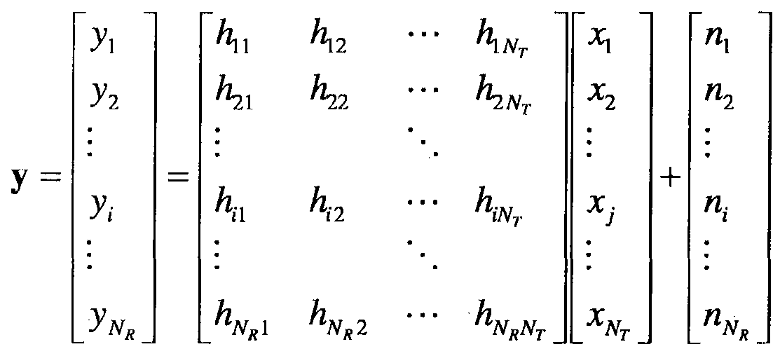
한편, 채널 상태를 나타내는 채널 행렬 H의 행과 열의 수는 송수신 안테나의 수에 의해 결정된다. 채널 행렬 H에서 행의 수는 수신 안테나의 수 과 같고, 열의 수는 송신 안테나의 수 와 같다. 즉, 채널 렬 Η는 행렬이 yV <yVr된다.
행렬의 랭크 (rank)는 서로 독립인 (independent) 행 또는 열의 개수 중에서 최소 개수로 정의된다. 따라서, 행렬의 탱크는 행 또는 열의 개수 보다 클 수 없다. 채널 행렬 H의 탱크 (ra« (H))는 다음과 같이 제한된다.
【수학식 111
rank K)≤ min (NT,NR)
랭크의 다른 정의는 행렬을 고유치 분해 (Eigen value decomposition) 하였을 띠 1, 0이 아닌 고유치들의 개수로 정의할 수 있다. 유사하게, 랭크의 또 다른 정의는 특이치 분해 (singular value decomposition) 하였을 때, 0이 아닌 특이치들의 개수로 정의할 수 있다. 따라서, 채널 행렬에서 탱크. 의 '물리적인 의미는 주어진
채널에서 서로 다른 정보를 보낼 수 있는 최대 수라고 할 수 있다.
본 문서의 설명에 있어서, MIM0 전송에 대한 '랭크 (Rank)' 는 특정 시점 및 특정 주파수 자원에서 독립적으로 신호를 전송할 수 있는 경로의 수를 나타내며, '레이어 (layer)의 개수' 는 각 경로를 통해 전송되는 신호 스트림의 개수를 나타낸다. 일반적으로 송신단은 신호 전송에 이용되는 랭크 수에 대응하는 개수의 레이어를 전송하기 때문에 특별한 언급이 없는 한 탱크는 레이어 개수와 동일한 의미를 가진디-.
이종 네트워크 환경 (Heterogeneous de loyments)
도 6은 매크로 (macro) 기지국과 마이크로 (micro) 기지국을 포함하는 이종 네트워크 무선 통신 시스템 (600)을 나타내는 도면이다. 본 문서에서 이종 네트워크 (heterogeneous network).라는 용어는, 동일한 RAT(Radio Access Technology)를 사용하더라도 매크로 기지국 (610)과 마이크로 기지국 (621, 622)이 공존하는 네트워크를 의미한다.
매크로 기지국 (610)은 넓은 커버리지 및 높은 전송 전력을 가지고, 무선 통신 시스템의 일반적인 기지국을 의미한다. 매크로 기지국 (610)은 매크로 셀로 칭할 수도 있다.
마이크로 기지국 (621, 622)은, 예를 들어, 마이크로 셀 (cell), 피코 샐 (pico cell), 펨토 셀 (femto cell), 홈 (home) eNB(HeNB) , 중계기 (relay) 등으로 칭하여질 수도 있다 (예시된 마이크로 기지국 및 매크로 기지국은 전송 포인트 (transmission point)로 통칭될 수도 있다). 마이크로 기지국 (621 및 622)은 매크로 기지국 (610)의 소형 버전으로 매크로 기지국의 기능을 대부분 수행하면서 독립적으로 작동할 수 있으며, 매크로 기지국이 커버하는 영역 내에
설치 (overlay)되거나 매크로 기지국이 커버하지 못하는 음영 지역에 설치 될 수 있는 (non— overlay) 유형의 기지국이다. 마이크로 기지국 (621 및 622)은 매크로 기지국 (610)에 비하여 좁은 커버리지 및 낮은 전송 전력을 가지고 보다 적은 개수의 단말을 수용할 수 있다.
단말 (631)은 매크로 기지국 (610)으로부터 직접 서빙받을 수도 있고 (이하 매크로ᅳ단말이라 함), 단말 (632)은 마이크로 기지국 (622)로부터 서빙받을 수도 있디- (이하, 마이크로-단말이라 함). 어떤 경우에는, 마이크로 기지국 -(622)의 커버리지 내에 존재하는 단말 (632)이 매크로 기지국 (610)으로부터 서빙받을 수도 있다.
' 단말의 액세스 제한 여부에 따라 마이크로 기지국은 :두 가지 타입으로 분류될 수 있디-. 첫 번째 타입은 CSG Closed Subscriber Group) 마이크로 기지국이고, 두 번째 타입은 OA (Open Access) 또는 0SC(0pen Subscriber Group) 마이크로 기지국이다. CSG 마이크로 기지국은 허가 받은 특정 단말들만 서빙할 수 있고, 0SG 마이크로 기지국은 별도의 액세스 제한 없이 모든 단말들을 서빙할 수 있다.
협력 멀티 포인트 (Coordinated Multi-Point: CoMP)
3GPP LTE-A 시스템의 개선된 시스템 성능 요구조건에 따라서, CoMP 송수신 기술 (co-MIM0, 공동 (collaborative) MIM0 또는 네트워크 MIM0 등으로 표현되기도 함)이 제안되고 있다. CoMP 기술은 셀 -경계 (cell -edge)에 위치한 단말의 성능을 증가시키고 평균 섹터 수율 (throughput)을 증가시킬 수 있다.
일반적으로, 주파수 재사용 인자 (frequency reuse factor)가 1 인 다중—셀 환경에서, 셀―간 간섭 (Inter— Cell Interference; ICI)으로 인하여 셀-경계에 위치한
단말의 성능과 평균 섹터 수율이 감소될 수 있다. 이러한 ICI를 저감하기 위하여, 기존의 LTE 시스템에서는 단말 특정 전력 제어를 통한 부분 주파수 재사용 (fractional frequency reuse; FFR)과 같은 단순한 수동적인 기법을 이용하여 간섭에 의해 제한을 받은 환경에서 셀-경계에 위치한 단말이 적절한 수율 성능을 가지도록 하는 방법이 적용되었다. 그러나, 샐 당 주파수 자원 사용을 낮추기보다는, ICI를 저감하거나 ICI를 단말이 원하는 신호로 재사용하는 것이 보다 바람직할 수 있다. 위와 같은 목적을 달성하기 위하여, CoMP 전송 기법이 적용될 수 있다.
하향링크의 경우에 적용될 수 있는 )MP 기법은 크게 조인트-프로세싱 (joint processing; JP) 기법 및 조정 스케줄링 /빔포밍 (coordinated scheduling/beamforming; CS/CB) 기법으로 분류할 수 있다.
JP 기법은 Cc)MP 협력 단위의 각각의 포인트 (기지국)에서 데이터를 이용할 수 있디ᅵ. CoMP 협력 단위는 협력 전송 기법에 이용되는 기지국들의 집합을 의미한디-. JP 기법은 조인트 전송 (Joint Transmission) 기법과 동적 셀 선택 (Dynamic cell selection) 기법으로 분류할 수 있다.
조인트 전송 기법은, PDSCH 가 한번에 복수개의 포인트 (CoMP 협력 단위의 일부 또는 전부)로부터 전송되는 기법을 말한다. 즉ᅵ 단일 단말로 전송되는 데이터는 복수개의 전송 포인트로부터 동시에 전송될 수 있다. 조인트 전송 기법에 의하면, 코히어런트하게 (coherently) 또는 넌―코히어런트하게 (non-coherent ly) 수신 신호의 품질이 향상될 수 있고, 또한, 다른 단말에 대한 간섭을 능동적으로 소거할 수도 있다.
동적 셀 선택 기법은, PDSCH가 한번에 (CoMP 협력 단위의) 하나의
포인트로부터 전송되는 기법을 말한다. 즉, 특정 시점에서 단일 단말로 전송되는 데이터는 하나의 포인트로부터 전송되고, 그 시점에 협력 단위 내의 다른 포인트는 해당 단말에 대하여 데이터 전송을 하지 않으며, 해당 단말로 데이터를 전송하는 포인트는 동적으로 선택될 수 있다.
한편, CS/CB 기법에 의하면 CoMP 협력 단위들이 단일 단말에 대한 데이터 전송의 빔포밍을 협력적으로 수행할 수 있다. 여기서, 데이터는 서빙 셀에서만 전송되지만, 사용자 스케줄링 /빔포밍은 해당 CoMP 협력 단위의 셀들의 조정에 의하여 결정될 수 있다.
한편, 상향링크의 경우에, 조정 (coordinated) 다중-포인트 수신은 지리적으로 떨어진 복수개의 포인트들의 조정에 의해서 전송된 신호를 수신하는 것을 의미한디-. 상향링크의 경우에 적용될 수 있는 CoMP 기법은 조인트 수신 (Joint Reception; JR) 및 조정 스케줄링 /빔포밍 (coordinated schedul ing/beamforming; CS/CB)으로 분류할 수 있다.
JR 기법은 PUSCH 를 통해 전송된 신호가 복수개의 수신 포인트에서 수신되는 것을 의미하고, CS/CB 기법은 PUSCH 가 하나의 포인트에서만 수신되지만 사용자 스케줄링 /빔포밍은 CoMP 협력 단위의 샐들의 조정에 의해 결정되는 것을 의미한다. 이러한 CoMP 시스템을 이용하면, 단말은 다중-셀 기지국 (Mult i— cell base station)으로부터 공동으로 데이터를 지원받을 수 있다. 또한, 각 기지국은 동일한 무선 주파수 자원 (Same Radio Frequency Resource)을 이용하여 하나 이상의 단말에 동시에 지원함으로써 시스템의 성능을 향상시킬 수 있다. 또힌ᅵ, 기지국은 기지국과 단말 간의 채널상태정보에 기초하여 공간 분할 다중접속 (Space Division Multiple Access: SOMA) 방법을 수행할 수도 있다.
CoMP 시스템에서 서빙 기지국 및 하나 이상의 협력 기지국들은 백본망 (Backbone Network)을 통해 스케줄러 (scheduler )에 연결된다. 스케줄러는 백본망을 통하여 각 기지국이 측정한 각 단말 및 협력 기지국 간의 채널 상태에 관한 채널 정보를 피드백 받아 동작할 수 있다. 예를 들어, 스케줄러는 서빙 기지국- 및 하나 이상의 협력 기지국에 대하여 협력적 MIM0 동작을 위한 정보를 스케줄링할 수 있다. 즉, 스케줄러에서 각 기지국으로 협력적 MIM0 동작에 대한 지시를 직접 내릴 수 있다.
상술한 바와 같0] CoMP 시스템은 복수개의 셀들을 하나의 그룹으로 묶어 가상 MIM0 시스템으로 동작하는 것이라 할 수 있으며, 기본적으로는 다중 안테나를 사용하는 MIM0 시스템의 통신 기법이 적용될 수 있다.
반송파 병합
도 7은 반송파 병합을 설명하기 위한 도면이다. 반송파 병합을 설명하기에 앞서 LTE-A에서 무선자원을 관리하기 위해 도입된 셀 (Cell)의 개념에 대해 먼저 설명한다. 셀은 하향링크 자원과 상향링크 자원의 조합으로 이해될 수 있디-. 여기서 상향링크 자원은 필수 요소는 아니며 따라서 셀은 하향링크 자원 단독 또는 하향링크 자원과 상향링크 자원으로 이루어질 수 있다. 다만, 이는 현재 LTE-A 릴리즈 10에서의 정의이며 반대의 경우, 즉 셀이 상향링크 자원 단독으로 이루어지는 것도 가능하다. 하향링크 자원은 하향링크 구성 반송파 (Downlink component carrier, DL CC)로 상향링크 자원은 상향링크 구성 반송파 (Uplink component carrier, UL CC)로 지칭될 수 있다. DL CC 및 UL CC는 반송파 주파수 (carrier frequency)로 표현될 수 있으며, 반송파 주파수는 해당 셀에서의 중심주파수 (center frequency)를 의미한다.
샐은 프라이머리 주파수 (primary frequency)에서 동작하는 프라이머리 셀 (primary cell , PCell)과 세컨더리 주파수 (secondary frequency)에서 동작하는 세컨더리 셀 (secondary cell, SCell)로 분류될 수 있다. PCell과 SCell은 서빙 샐 (serving cell)로 통칭될 수 있다. PCell은 단말이 초기 연결 설정 (initial connection establishment) 과정을 수행하거나 연결 재설정 과정 또는 핸드오버 과정에서 지시된 샐이 PCell이 될 수 있다. 즉, PCell은 후술할 반송파 병합 환경에서 제어관련 중심이 되는 샐로 이해될 수 있다. 단말은 자신의 PCell에서 PUCCH를 할당 받고 전송할 수 있다. SCell은 RRC(Radio Resource Control) 연결 설정이 이루어진 이후 구성 가능하고 추가적인 무선 자원을 제공하는데 사용될 수 있디-. 반송파 병합 환경에서 PCell을 제외한 나머지 서빙 셀을 SCell로 볼 수 있디-. RRC— CONNECTED 상태에 있지만 반송파 병합이 설정되지 않았거나 반송파 병합을 지원하지 않는 단말의 경우, PCell로만 구성된 서빙 셀이 단 하나 존재한다. 반면, RRC— CONNECTED 상태에 있고 반송파 병합이 설정된 단말의 경우, 하니- 이상의 서빙 씰이 존재하고, 전체 서빙 샐에는 PCell과 전체 SCell이 포함된디-. 반송파 병합을 지원하는 단말을 위해 네트워크는 초기 보안 활성화 (initial security activation) 과정이 개시된 이후, 연결 설정 과정에서 초기에 구성되는 PCell에 부가하여 하나 이상의 SCell을 구성할 수 있다.
이히-, 도 7을 참조하여 반송파 병합에 대해 설명한다. 반송파 병합은 높은 고속 전송를에 대한 요구에 부합하기 위해 보다 넓은 대역을 사용할 수 있도록 도입된 기술이다. 반송파 병합은 반송파 주파수가 서로 다른 2개 이상의 구성 반송파 (component carrier, CC)들의 집합 (aggregat ion)으로 정의될 수 있디-. 도 7을 참조하면, 도 7(a)는 기존 LTE 시스템에서 하나의 CC를 사용하는 경우의
서브프레임을 나타내고, 도 7(b)는 반송파 병합이 사용되는 경우의 서브프레임을 나타낸다. 도 7(b)에는 예시적으로 20MHz의 CC 3개가 사용되어 총 60MHz의 대역폭을 지원하는 것을 도시하고 있다. 여기서 각 CC는 연속적일 수도 있고, 또한 비 연속적일 수도 있다.
단말은 하향링크 데이터를 복수개의 DL CC를 통해 동시에 수신하고 모니터할 수 있디-. 각 DL CC와 UL CC 사이의 링키지 (linkage)는 시스템 정보에 의해 지시될 수 있디ᅵ. DL CC/UL CC 링크는 시스템에 고정되어 있거나 반-정적으로 구성될 수 있디-. 또한, 시스템 전체 대역이 N개의 CC로 구성되더라도 특정 단말이 모니터링 /수신할 수 있는 주파수 대역은 M(<N)개의 CC로 한정될 수 있다. 반송파 병합에 대한 다양한 파라미터는 셀 특정 (cell-specific), 단말 그룹 특정 (UE group-specific) 또는 단말 특정 (UE-specific) 방식으로 설정될 수 있다.
도 8은 크로스 반송파 스케줄링을 설명하기 위한 도면이디-. 크로스 반송파 스케줄링이란, 예를 들어, 복수의 서빙 셀 중 어느 하나의 DL CC의 제어영역에 다른 DL CC의 하향링크 스케줄링 할당 정보를 모두 포함하는 것, 또는 복수의 서빙 셀 중 어느 하나의 DL CC의 제어영역에 그 DL CC와 링크되어 있는 복수의 UL CC에 대한 상향링크 스케줄링 승인 정보를 모두 포함하는 것을 의미한다.
먼저 반송파 지시자 필드 (carrier indicator field, CIF)에 대해 설명한다. CIF는 앞서 설명된 바와 같이 PDCCH를 통해 전송되는 DCI 포맷에 포함되거나 또는 불포함 수 있으며, 포함된 경우 크로스 반송파 스케줄링이 적용된 것을 나타낸디-. 크로스 반송파 스케줄링이 적용되지 않은 경우에는 하향링크 스케줄링 할당 정보는 현재 하향링크 스케줄링 할당 정보가 전송되는 DL CC상에서 유효하다. 또한 상향링크 스케줄링 승인은 하향링크 스케줄링 할당 정보가 전송되는 DL CC 와
링크된 하나의 UL CC에 대해 유효하다.
크로스 반송파 스케줄링이 적용된 경우, CIF는 어느 하나의 DL CC에서 PDCCH를 통해 전송되는 하향링크 스케줄링 할당 정보에 관련된 CC를 지시한다. 예를 들어 , 도 8을 참조하면 DL CC A 상의 제어 영역 내 PDCCH를 통해 DL CC B 및 DL CC Oil 대한 하향링크 할당 정보, 즉 PDSCH 자원에 대한 정보가 전송된디-. 단말은 DL CC A를 모니터링하여 CIF를 통해 PDSCH의 자원영역 및 해당 CC를 알 수 있다.
PDCCH에 CIF가 포함되거나 또는 포함되지 않는지는 반-정적으로 설정될 수 있고, 상위 계층 시그널링에 의해서 단말-특정으로 활성화될 수 있다. CIF가 비활성화 (disabled)된 경우에, 특정 DL CC 상의 PDCCH는 해당 동일한 DL CC 상의 PDSCH 자원을 할당하고, 특정 DL CC에 링크된 UL CC 상의 PUSCH 자원을 할당할 수 있디-. 이 경우, 기존의 PDCCH 구조와 동일한 코딩 방식, CCE 기반 자원 매핑, DCI 포맷 등이 적용될 수 있다. '
한편, CIF가 활성화 (enabled)되는 경우에, 특정 DL CC 상의 PDCCH는 복수개의 병합된 CC들 중에서 CIF가 지시하는ᅵ하나의 DL/UL CC 상에서의 PDSC1I/PUSCH 자원을 할당할 수 있디-. 이 경우, 기존의 PDCCH DCI 포맷에 CIF가 추가적으로 정의될 수 있으며, 고정된 3 비트 길이의 필드로 정의되거나, CIF 위치가 DCI 포맷 크기에 무관하게 고정될 수도 있다ᅳ 이 경우에도, 기존의 PDCCH 구조와 동일한 코딩 방식, CCE 기반 자원 매핑, DCI 포맷 등이 적용될 수 있다.
CIF가 존재하는 경우에도, 기지국은 PDCCH를 모니터링할 DL CC 세트를 할당할 수 있다. 이에 따라, 단말의 블라인드 디코딩의 부담이 감소할 수 있디-. PDCCH 모니터링 CC 세트는 전체 병합된 DL CC의 일부분이고 단말은 PDCCH의 검출 /디코딩을 해당 CC 세트에서만 수행할 수 있다. 즉, 단말에 대해서 PDSCH/PUSCH를
스케줄링하기 위해서, 기지국은 PDCCH를 PDCCH 모니터링 CC 세트 상에서만 전송할 수 있디-. PDCCH 모니터링 DL CC 세트는 단말 -특정 또는 단말 그룹—특정 또는 썰-특정으로 설정될 수 있다. 예를 들어, 도 8의 예시에서와 같이 3 개의 DL CC가 병합되는 경우에, DL CC A 가 PDCCH 모니터링 DL CC로 설정될 수 있다. CIF가 비활성화되는 경우, 각각의 DLCC상의 PDCCH는 DLCCA에서의 PDSCH만을 스케줄링할 수 있다. 한편, CIF가 활성화되면 DL CC A 상의 PDCCH는 DL CC A는 물론 다른 DL CC에서의 PDSCH 도 스케줄링할 수 있다. DL CC A가 PDCCH 모니터링 CC로 설정되는 설정되는 경우에는 DL CC B 및 DL CC C 에는 PDSCCH가 전송되지 않는다. .
전술한 바와 같은 반송파 병합이 적용되는 시스템에서, 단말은 복수개의 하향링크 반송파를 통해서 복수개의 PDSCH를 수신할 수 있고, 이러한 경우 단말은 각각의 데이터에 대한 ACK/NACK을 하나의 서브프레임에서 하나의 UL CC 상에서 전송하여야 하는 경우가 발생하게 된다. 하나의 서브프레임에서 복수개의 ACK/NACK을 PUCCH 포맷 la/lb을 이용하여 전송하는 경우, 높은 전송 전력이 요구되며 상향링크 전송의 PAPR이 증가하게 되고 전송 전력 증폭기의 비효율적인 사용으로 인하여 단말의 기지국으로부터의 전송 가능 거리기■ 감소할 수 있디-. 하나의 PUCCH를 통해서 복수개의 ACK/NACK을 전송하기 위해서는 ACK/MCK 번들링 (bundling) 또는 ACK/NACK다중화 (mult iplexing)이 적용될 수 있다.
또한, 반송파 병합의 적용에 따른 많은 개수의 하향링크 데이터 및 /또는 TDD 시스템에서 복수개의 DL 서브프레임에서 전송된 많은 개수의 하향링크 데이터에 대한 ACK/NACK 정보가 하나의 서브프레임에서 PUCCH를 통해 전송되어야 하는 경우가 발생할 수 있다. 이러한 경우에서 전송되어야 할 ACK/NACK 비트가 ACK/NACK 번들링 또는 다증화로 지원가능한 개수보다 많은 경우에는, 위 방안들로는
올바르게 ACK/NACK 정보를 전송할 수 없게 된다.
하향링크 채널상태정보 (CSI) 피드백
MIM0 방식은 개—루프 (open— loop) 방식과 폐 -루프 (closed— loop) 방식으로 구분될 수 있다. 개—루프 MIM0 방식은 MIM0 수신단으로부터의 채널상태정보의 피드백이 없이 송신단에서 MIM0 전송을 수행하는 것을 의미한다. 폐 -루프 MIM0 방식은 MIM0 수신단으로부터의 채널상태정보를 피드백 받아 송신단에서 MIM0 전송을 수행하는 것을 의미한다. 폐 -루프 MIM0 방식에서는 MIM0 송신 안테나의 다중화 이득 (multiplexing gain)을 얻기 위해서 송신단과 수신단의 각각이 채널 상태정보를 바탕으로 빔포밍을 수행할 수 있다ᅳ 수신단 (예를 들어, 단말)이 채널상태정보를 피드백할 수 있도록 송신단 (예를 들어, 기지'국)은 수신딘- (예를 들어, 단말)에게 상향링크 제어 채널 또는 상향링크 공유 채널을 할당할 수 있다. 피드백되는 채널상태정보 (CSI)는 랭크 지시자 (RI), 프리코딩 행렬 인덱스 (PMI) 및 채널품질지시자 (CQI)를 포함할 수 있다.
RI는 채널 탱크에 대한 정보이다. 채널의 랭크는 동일한 시간-주파수 자원을 통해서 서로 다른 정보를 보낼 수 있는 레이어 (또는 스트림)의 최대 개수를 의미한다. 랭크 값은 채널의 장기간 (long term) 페이딩에 의해서 주로 결정되므로, PMI 및 CQI 에 비하여 일반적으로 더 긴 주기에 따라 피드백될 수 있디-.
PMI는 송신단으로부터의 전송에 이용되는 프리코딩 행렬에 대한 정보이며, 채널의 공간 특성을 반영하는 값이다. 프리코딩이란 전송 레이어를 송신 안테나에 매핑시키는 것을 의미하며, 프리코딩 행렬에 의해 레이어—안테니- 매핑 관계가 결정될 수 있다. PMI 는 신호대잡음및간섭비 (Signal-to— Interference plus Noise Ratio; SINR) 등의 측정값 (metric)을 기준으로 단말이 선호하는 (preferred)
기지국의 프리코딩 행렬 인덱스에 해당한다. 프리코딩 정보의 피드백 오버헤드를 줄이기 위해서 ,·송신단과 수신단이 여러 가지 프리코딩 행렬을 포함하는 코드북을 미리 공유하고 있고, 해당 코드북에서 특정 프리코딩 행렬을 지시하는 인덱스만을 피드백하는 방식이 사용될 수 있다.
CQI는 채널 품질 또는 채널 세기를 나타내는 정보이다. CQI는 미리 결정된
MCS 조합으로서 표현될 수 있다. 즉, 피드백되는 CQI 인텍스는 해당하는 변조기법 (modulation scheme) 및 코드 레이트 (code rate)를 나타낸디-. 일반적으로, CQI 는 기지국이 PMI 를 이용하여 공간 채널을 구성하는 경우에 얻을 수 있는 수신 SIN 을 반영하는 값이 된다.
확장된 안테나 구성을 지원하는 시스템 (예를 들어, LTE-A 시스템)에서는 다중사용자 -MIM0 (MU-MIM0) 방식을 이용하여 추가적인 다중사용자 다이버시티를 획득하는 것을 고려하고 있다. MU-MIM0 방식에서는 안테나 영역 (domain)에서 다중화되는 단말들 간의 간섭 채널이 존재하므로, 다중사용자. 중 하나의 단말이 피드백하는 채널상태정보를 기지국에서 이용하여 하향링크 전송을 수행하는 경우에 다론 단말에 대해서 간섭이 발생하지 않도록 하는 것이 필요하다. 따라서 , MU-MIM0 동작이 올바르게 수행되기 위해서는 단일사용자 -MIM0 (SU-MIM0) 방식에 비하여 보다 높은 정확도의 채널상태정보가 피드백되어야 한다.
이와 같이 보다 정확한 채널상태정보를 측정 및 보고할 수 있도록, 기존의 RI, PMI 및 CQI 로 구성되는 CSI 를 개선한 새로운 CSI 피드백 방안이 적용될 수 있디-. 예를 들어, 수신단이 피드백하는 프리코딩 정보가 2 개의 PMI 의 조합에 의해서 지시될 수 있다. 2 개의 PMI 중 하나 (제 1 PMI)는, 장기간 및 /또는 광대역 (long term and/or wideband)의 속성을 가지고, W1으로 지칭될 수 있다.2 개의
PMI 중 다른 하나 (제 2 ΡΜΙ)는, 단기간 및 /또는 서브대역 (short term and/or subband)의 속성을 가지고, W2으로 지칭될 수 있다. W1 및 W2의 조합 (또는 함수)에 의해서 최종적인 PMI가 결정될 수 있다. 예를 들어, 최종 PMI 를 W 라 하면, W=W1*W2 또는 W=W2*W1 과 같이 정의될 수 있다.
여기서, W1 은 채널의 주파수 및 /또는 시간상 평균적인 특성을 반영한다. 다시 말하자면, W1 은 시간 상에서 장기간 (long term) 채널의 특성을 반영하거나, 주파수 상에서 광대역 (wideband) 채널의 특성을 반영하거나, 또는 시간상에서 장기간인 동시에 주파수 상에서 광대역 채널의 특성을 반영하는 채널 상태 정 로서 정의될 수 있다. W1 의 이러한 특성을 간략하게 표현하기 위해서, 본 문서에서는 W1 를 장기간-광대역 속성의 채널 상태 정보 (또는, 장기간—광대역 PMI)라고 한다.
한편, W2 는 W1 에 비하여 상대적으로 순간적인 (instantaneous) 채널 특성을 반영한다. 다시 말하자면, W2 는 시간 상에서 단기간 (short term) 채널의 특성을 반영하거니-, 주파수 상에서 서브대역 (subband) 채널의 특성을 반영하거니-, 또는 시간상에서 단기간인 동시에 주파수 상에서 서브대역 채널의 특성을 반영하는 채널 상태 정보로서 정의될 수 있다. W2 의 이러한 특성을 간략하게 표현하기 위해서, 본 문서에서는 W1 를 단기간-서브대역 속성의 채널 상태 정보 (또는, 단기간—서브대역 PMI)라고 한디-.
채널 상태를 나타내는 2 개의 서로 다른 속성의 정보 (예를 들어, W1 및 W2)로부터 하나의 최종 프리코딩 행렬 (W)을 결정할 수 있도록 하기 위해서, 각각의 속성의 채널 정보를 나타내는 프리코딩 행렬들로 구성되는 별도의 코드북 (즉, W1 에 대한 제 1 코드북 및 W2 에 대한 제 2 코드북)을 구성할 필요기- 있디-. 이와 같이
구성되는 코드북의 형태를 계층적 코드북 (hierarchical codebook)이라 할 수 있다. 또힌-, 계층적 코드북을 이용하여 최종 사용될 코드북을 결정하는 것을, 계층적 코드북 변환 (hierarchical codebook transformat ion)이라 할 수 있다.
계충적 코드북 변환. 방식의 일례로서, 다음 수학식 12 외- 같이 채널의 장기간 공분산 행렬 (long term covariance matrix)을 이용하여 코드북을 변환할 수 있다.
【수학식 12】
W =厦 (WlW2)
상기 수학식 12 에서 W1 (장기간-광대역 PMI)은 장기간-광대역 속성의 채널 정보를 반영하기 위해 만들어진 코드북 (예를 들어, 제 1 코드북)을 구성하는 요소 (즉, 코드워드 (codeword))를 나타낸다. 즉, W1은 장기간—광대역 속성의 채널 정보를 반영하는 제 1 코드북에 포함되는 프리코딩 행렬에 해당한다. 한편, W2(단기간-서브대역 PMI)는 단기간-서브대역 속성의 채널 정보를 반영하기 위해서 만들어진 코드북 (예를 들어,제 2 코드북)을 구성하는 코드워드를 나타낸다. 즉, W2는 단기간-서브대역 속성의 채널 정보를 .반영하는 제 2 코드북에 포함되는 프리코딩 행렬에 해당한다. W는 변환된 최종 코드북의 코드워드를 나타낸다. nonri )는 행렬 A의 각각의 열 (column)별 norm이 1로 정규화 (normal izat ion)된 행렬을 의미한디-.
과 W2는 예시적으로 다음의 수학식 13과 같은 구조를 가질 수 있다. 【수학식 13】

r columns
e J m
M
W2(y) = (if rank = r)
상기 수학식 13 에서 Wl는 블록대각행렬 (block diagonal matrix) 형태로서 정의될 수 있고, 각각의 블록은 동일한 행렬 (X/)이다. 하나의 블록 (X/)은 (Nt/2)XM 크기의 행렬로서 정의될 수 있다. 여기서, Nt 는 전송 안테나의 개수이다. 상기
P
수학식 13 에서 W2의 게 1 Z?)는 MX1 크기의 백터이며 , M 개의 백터 성분 중에서 p 번째 성분은 1 이고, 나머지 성분들은 0 인 백터를 나타낸디-.
가 W1과 곱해지는 경우에 W1의 열들 (columns) 중에서 p 번째 열이 선택되므로, 이러힌- 백터를 선택 백터 (selection vector)라고 할 수 있다. 여기서 , M 값이 커질수록 장기간—광대역 (long term/wideband) 채널을 표현하기 위해 한번에 피드백 되는 백터의 수가 많아지게 되며 이에 따라 피드백 정확도가 높아지게 된다. 하지만 M 값이 커질 수록, 낮은 빈도로 피드백되는 W1의 코드북 크기 (codebook size)는 줄어들고, 높은 빈도로 피드백되는 의 코드북 크기기- 늘어남에 따라 결과적으로 피드백 오버헤드가 늘어나게 된다. 즉, 피드백 오버헤드
정확도 간에 트레이드 -오프 (tradeoff)가 존재한다ᅳ 따라서, 적절한 피드백 정확도를 유지하면서도 피드백 오버헤드가 너무 크게 증가하지 않도록 M 값을 결정할 수 있다. 한편, W2 에서 는 각각 소정의 위상값을 나타낸다 상기 수학식 13 에서 1≤ ^ / H≤M 이고, k, 1, m은 각각 정수 (integer)이다.
상기 수학식 13 과 같은 코드북 구조는, 크로스—극성 (cross polarized; X-pol)
안테나 구성 (configuration)을 사용하면서 안테나 간 간격이 조밀한 경우 (통상적으로, 인접 안테나 간 거리가 신호 파장의 반 이하인 경우)에 발생하는 채널의 상관 (correlation) 특성을 잘 반영하도록 설계한 구조이디-. 예를 들어, 크로스 -극성 안테나 구성은 다음의 표 1과 같이 나타낼 수 있다.
【표 1】

상기 표 1에서 8Tx 크로스 -극성 안테나 구성은, 2 개의 서로 직교하는 국 -성을 가지는 안테나 그룹으로 구성된다고 표현할 수 있다. 안테나 그룹 1 (안테나 1, 2. 3. 4)의 안테나들은 동일한 극성 (예를 들어 수직 극성 (vertical polarizat ion))을 가지고 안테나 그룹 2(안테나 5, 6, 7, 8)의 안테나들은 동일한 극성 (예를 들어 수평 극성 (horizontal polar ization))을 가질 수 있다. 또한, 두 안테나 그룹은 동일한 위치에 위치한다 (co-located). 예를 들어, 안테나 1 과 5 는 동일한 위치에 설치되고, 안테나 2 과 6 은 동일한 위치에 설치되고, 안테나 3 과 7 은 동일한 위치에 설치되고, 안테나 2 과 8 은 동일한 위치에 설치될 수 있디 ·. 달리 표현하자면, 하나의 안테나 그룹 내의 안테나들은 ULA Jniform Linear Array)와 같이 동일한 극성을 가지고, 하나의 안테나 그룹 내의 안테나 간의 상관 (cor relation)은 선형 위상 증가 (linear phase increment) 특성을 가진다. 또한,
안테나 그룹 간의 상관은 위상 회전 (phase rotation)된 특성을 갖는다. 코드북은 채널을 양자화 (quantization)한 값이기 때문에, 실제 채널의 특성을 그대로 반영하여 코드북을 설계하는 것이 필요하다. 이와 같이 실제 채널 특성이 상기 수학식 13 과 같이 설계된 코드북의 코드워드에 반영되었음을 설명하기 위해서, 탱크 1 코드북을 예시적으로 설명한다. 아래의 수학식 14 는 탱크 1 인 경우의 W1 코드워드와 W2 코드워드의 곱으로 최종 코드워드 (W)가 결정되는 예시를 나타낸 것이다.
【수학식 14】
Wl(z) * W2(y) =
a}Xt(k) 상기 수학식 14 에서 최종 코드워드는 Ntxi 의 백터로 표현되며, 상위 백터 (X,( )와 하위 백터 ( .Χ Α:))의 두 개의 백터로 구조화되어 있다. 상위 백터 ( Χ,(^))는 크로스 극성 안테나의 수평 극성 안테나 그룹의 상관 특성을 나타내고, 하위 백터 ( χ( ))는 수직 극성 안테나 그룹의 상관 특성을 나타낸다. 또한, Χ,(:)는 각각의 안테나 그룹 내의 안테나 간 상관 특성을 반영하여 선형 위상 증가를 갖는 백터 (예를 들어, DFT 행렬)로 표현할 수 있다.
계충적 코드북 변환 방식의 다른 예로서, 다음 수학식 15 외 같이 채널의 장기간 공분산 행렬 (long term covar iance matrix)을 이용하여 코드북을 변환할 수 있다.
【수학식 15】
W1 = R
W =續 7<W1W2) 상기 수학식 15 에서 Wl (장기간-광대역 PMi) 는 장기간-광대역 속성의 채널 정보를 반영하기 위해 만들어진 코드북 (예를 들어, 게 1 코드북)을 구성하는 요소 (즉, 코드워드 (codeword))를 나타낸다. 즉, W1은 장기간—광대역 속성의 채널 정보를 반영하는 제 1 코드북에 포함되는 프리코딩 행렬에 해당한다. 한편, W2 (단기간-서브대역 PMI) 는 단기간—서브대역 속성의 채널 정보를 반영하기 위해서 만들어진 코드북 (예를 들어, 제 2 코드.북)을 구성하는 코드워드를 나타낸디-. 즉,
W2 는 단기간-서브대역 속성의 채널 정보를 반영하는 제 2 코드북에 포함되는 프리코딩 행렬에 해당한다. W 은 변환된 최종 코드북의 코드워드를 나타낸디-. norm(A) 은 행렬 A 의 각각의 열 (column)에 대한 놈 (norm)이 i 로 정규화 (normalization)된 행렬을 의미한다. 상기 수학식 15 에서 W1은 채널 H 의 장기간 공분산 행렬인 R 로 표현된다고 가정하며, R 은 아래의 수학식 16 과 같이 표현될 수 있다.
【수학식 16]
( ) Nt
Η
R = E Η ΊΗ = VAV^ -Υσ,ν,.ν,.
=1
(a)
상기 수학식 16 에서 ᅳ 는 Ε ^L Η"^Η "J 를 특이치 분해 (singular value decomposition)에 의해 얻은 결과가 VAV 임을 나타낸다. 또한, 웨 는
각각 i 번째 특이치 (singular value)와 그에 상웅하는 i 번째 특이열백터 (singular column vector) 를 의미한다. 여기서, σ1≥ ≥…≥ σΜ 이다. 예를 들어 송신 스트림의 개수가 1 개인 경우, W2 는 Nt X 1 크기의 백터이고, W 는 다음의 수학식 17 과 같이 표현될 수 있다. 【수학식 17】
 상기 수학식 17 에세 W은 각각의 특이백터들의 가중 선형 조합 (weighted
V;
linear combinat ion)으로 결정된다. 여기서, '의 가중 인자 (weighted factor)는, 특이치 값 σ' 과, V ' 와 코드워드 W2 간의 상관 (correlation)인 V' W2의 곱으로 결정된다. 그 결과 W로 구성된 코드북의 코드워드 분포는, σ'' 값이 큰 지배적인 (dominant) 특이백터에 보다 집중되므로, 보디- 효과적인 양자화 (Quantization)가 가능하다. 도 9 및 도 10은 계층적 코드북 변환이 적용되는 경우에 보다 효과적으로 채널 상태를 반영할 수 있음을 설명하기 '위한 도면이다. 도 9 및 도 10은 Nt=2 를 가정하여 (즉, 송신 안테나의 개수가 2 개인 것 (2Tx)을 가정하여) 2 차원 공간을 나타낸 것이며, 이는 설명의 편의를 위한 것일 뿐 이에 제한되는 것은 아니다. 2 차원 공간은 설명의 편의상 기저 1 (basis 1) 및 기저 2 (basis 2)에 의하여 구성되는 것을 가정한다. 도 9에서는 하나의 코드북 (즉, W2 코드북) 만이 사용되는 경우를 나타내고, 도 10에서는 2 개의 코드북 (즉, W1 코드북 및 W2
코드북) 을 이용하여 계층적 코드북 변환에 의해 결정되는 코드북 (즉, W 코드북) 이 사용되는 경우를 나타낸다.
도 9는 2 차원 공간 상에 존재하는 특이벡터 (제 1 지배 특이백터 및 제 2 지배 특이백터) 및 W2 (즉, W2 코드북의 코드워드들)을 나타낸 것이다. 제 1 지배 특이백터는 게 2 지배 특이백터보다 더 큰 가중치를 가지는 특이백터를 의미한디-. 도 9의 예시와 다른 형태로 W2 코드워드들이 분포할 수도 있지만, 도 9 의 예시에서는 일반적으로 채널이 존재하는 그라스마니안 공간 (Grassmannian space) 내에서 2 개의 W2 코드워드 간의 최소 거리를 최대화하는 방식에 따라서
(즉, 균일하게) W2 코드워드들이 분포된 것을 가정한다. 이에 따리-, 제 1 지배 특이백터 및 게 2 지배 특이백터의 합으로 표현될 수 있는 W2 코드워드들 중에서 제 1 지배 특이백터에 보다 가까운 W2 코드워드 (도 8 의 기저 1 축 상에 위치한
W2 )가 결정될 수 있다. 이와 같이 설계된 ( 코드북을 이용하는 경우에, 비상관 (uncorrelated) 채널에서 좋은 성능을 얻을 수 있지만, 상관 (correlated) 채널에서는 성능이 떨어진다. 더욱이 상관 채널에서는 순간적인 (instantaneous) 채널 H의 특이백터와 R의 특이 백터 간에 상관성이 높기 때문에, 이러한 관계를 이용하여 코드북을 R에 따라 적웅적으로 변환하면 보다 효과적이디-.
도 10에서는 2 차원 공간 상에 존재하는 특이백터 (제 1 지배 특이백터 및 제 2 지배 특이백터) 및 W (즉, W1 과 W2 코드북을 이용한 코드북 변환에 의해 생성된 코드워드들)을 나타낸 것이다. 도 10에서 도시하는 바와 같이, 코드북 변환이 적용되는 경우에 전술한 바와 같이 R의 제 1 지배 특이 백터에 더 큰
가중치가 적용되어, 제 1 지배 특이 백터를 기준으로 새로운 코드워드들이 보다 조밀한 분포를 가질 수 있다. 즉, 실제 채널 상태를 '보다 정확하게 반영할 수 있는 코드워드의 선택이 가능해진다.
상술한 바와 같이 W1과 W2를 이용한 계층적 코드북을 이용하여 프리코딩을 수행 또는 PMI를 포함하는 CSI의 보고는 피드백 되는 채널 정보의 정확도를 높일 수 있지만, W1 및 W2가 각각 하나의 코드북으로부터 선택되는 경우 진보된 통신 환경에서는 그 성능이 층분히 발휘되기 어려울 수도 있다. 진보된 통신 환경에서는 보다 다양한 채널 특성이 나타날 것이고 이러한 다양한 채널 특성을 어떤 하나의 코드북으로 모두 표현하기가 어렵기 때문이다. 여기서 진보된 통신 환경에는 이종 네트워크 환경 또는 반송파 병합의 경우가 이에 해당할 수 있다.
이종 네트워크 환경의 경우 매크로 기지국과 마이크로 기지국이 단말에 대해 협력 전송을 수행하는 경우, 매크로 기지국으로부터의 하향링크 신호와 마이크로 기지국으로부터의 하향링크 신호는 송신 전력 등의 차이로 인해 비대칭적인 채널 구조를 기-질 수 있다. 이러한 비대칭적 채널을 하나의 코드북으로 모두 반영하기에는 한계가 있다. 반송파 병합의 경우, 사용되는 구성 반송파들의 주파수 대역이 크게 떨어져 있는 경우 (예를 들어, CC1은 700腿 z, CC2는 3.5GHz 대역의 반송파를 사용하는 경우), 각 구성 반송파가 겪는 채널은 상이할 수 있고, 이 때에도 하나의 코드북으로 두 개의 구성 반송파의 채널을 표현하기는 효율적이지 못할 수 있다.
따라서, 이하에서는 전송 포인트와 단말 사이 채널을 표현하기 위한 복수개의 코드북이 존재하며, 전송 포인트와 단말은 복수개의 코드북 중 통신 환경에 최적화된 코드북을 선택하여 사용하는 방식을 제안한다. 여기서 코드북
선택에 관한 정보는 상위계층 시그널링 (RRC control signaling)을 전송 포인트와 단말 사이에 공유될 수 있다.
우선 이종 네트워크 환경에서의 계층적 코드북 사용에 대해 설명한다. 이하의 설명에서, 이종 네트워크 환경은 두 개의 전송 포인트와 단말로 이루어지며 두 개의 전송 포인트 중 하나는 매크로 기지국, 나머지 하나는 마이크로 기지국인 것을 전제로 한다. 또한, 매크로 기지국과 마이크로 기지국은 동일한 셀 식별자 (ID)를 가지며 단말에 대해 하향링크 신호를 협력 전송한다. 이외- 같은 이종 네트워크 환경에서 단말과 전송 포인트들은 앞서 설명된 계층적 코드북이 수정된 코드북을 사용할 수 있다. 구체적으로 장기간-광대역 채널 특성을 반영하는 상술한 코드북에 전송 포인트와 단말의 관계를 반영하는 보정 인자 (revision factor)가 적용된 제 1 코드북으로부터 제 1 프리코딩 행렬 (W1)을 선택하고, 단기간 및 /또는 서브대역 채널 특성이 반영된 제 2 코드북으로부터 제 2 프리코딩 행렬 (W2)을 선택함으로써 최종 프리코딩 행렬을 결정할 수 있다. 이는 앞서 설명된 장기간-광대역 채널 특성을 반영하는 코드북 및 통신 환경을 반영하는 서로 다른 보정 인자가 적용된 복수개의 코드북들이 미리 준비되어 있고, 이로부터 전송 포인트가 적절한 코드북을 결정하고 제 1 프리코딩 행렬 (W1)을 선택하는 것으로 이해될 수도 있다.
이와 같은 게 1 프리코딩 행렬 (W1) 및 제 2 프리코딩 행렬 (W2)는 다음 수학식 18 과 같이 표현될 수 있다.
【수학식 18】
X 0
Wl(
0 pX

싱-기 수학식 18 에서 Wl는 블록대각행렬 형태로서 정의될 수 있고, 각각의 블록은 동일한 행렬 (X/)이다. 하나의 블록 (X/)은 (Nt/2)XM 크기의 행렬로서 정의될 수 있다. 여기서, Nt 는 전송 안테나의 개수이다. 상기 수학식 18 에서 W2의 i {p-k, 1, ..., m)는 MX1 크기의 백터이며, M 개의 백터 성분 중에서 p번째 성분은
1 이고, 나머지 성분들은 0 인 백터를 나타낸다. W2 에서 aj , , 7j 는 각각 소정의 위상값을 나타낸디-. 1 < k, /, 7; ≤ M 이고, /77은 각각 정수이디-. P 는 보정 인자로써, 단말 특정 (UE— specific)한 것일 수 있디 여기서 P 는 마이크로 기지국으로부터 수신되는 채널의 크기가 매크로 기지국으로부터 수신되는 채널의 크기보다 작음을 고려하여 1보다 작은 값으로 설정된 것일 수 있다. P 값은 고정된 값 또는 가변적인 값일 수 있고, 가변적인 값을 가지는 경우 전송 포인트와 단말 사이에 공유될 수 있다.
상술한 설명들을 단말 및 전송 포인트의 동작 측면에서 도 11 내지 도 12를 참조하여 설명하면 다음과 같다.
도 11을 참조하면, 단말은 전송 포인트로.부터 참조신호를 수신할 수
- 있다 (S1101). 여기서 참조신호는 LTE-A 릴리즈 10에 도입된 여덟개의 레이어의 공간 다중화를 지원하기 위한 채널 상태 정보 참조신호 (CSI— RS)일 수 있다. 또한, 참조신호는 각각의 전송 포인트, 즉 매크로 기지국과 마이크로 기지국으로부터 수신될 수 있다. 참조신호를 수신한 단말은 참조신호애 기초하여 전송
포인트로부터 사용이 결정된 제 1 코드북으로부터 제 1 프리코딩 행렬 (W1) 및 제 2 코드북으로부터 제 2 프리코딩 행렬 (W2)을 결정할 수 있다 (S1102). 여기서 게 1 코드북에서 선택되는 게 1 프리코딩 행렬은, 앞서 설명된 장기간-광대역 채널 특성을 반영하는 것으로써 단말이 속해 있는 통신 환경을 반영하는 보정 인자 P 기- 적용된 것이디- .
계속해서, 단말은 제 1 프리코딩 행렬의 인덱스 및 게 2 프리코딩 행렬의 인텍스로 이루어진 PMI를 포함하는 채널 상태 정보를 생성하여 전송 포인트로 송신할 수 있다 (S1103). 여기서, 채널 상태 정보는, 전송 포인트의 요청, 즉 CSI 요청 (request)에 의한 비 주기적인 것일 경우 PUSCH 상으로 전송되며, 주기적인 CS1 보고인 경우 PUCCH 상으로 전송될 수 있다.
도 12를 참조하면, 전송 포인트는 단말로부터의 채널 상태 보고를 수신할 수 있다 (S1201). 앞서 설명된 것과 같이 단말로부터의 채널, 상태 보고는 주기적인 것일 수도, 비주기적인 것일 수도 있다.
전송포인트는 단말로부터 보고받은 채널 상태 정보에 포함된 PMI에 따라 프리코딩 행렬을 선택할 수도 있지만, 이에 종속되지 않고 프리코딩 행렬을 선택할 수도 있다 (S1202). 단말로부터의 PMI에 따라 프리코딩 행렬을 선택하는 경우, 프리코딩 행렬을 결정하기 위한 제 1 프리코딩 행렬의 인덱스 및 제 2 프리코딩 행렬의 인덱스로부터 프리코딩 행렬을 선택하고 (S1203), 이 프리코딩 행렬을 이용하여 프리코딩을 수행할 수 있다 (S1204). 이 경우, 전송 포인트는 단말이 송신한 PMI에 따른 프리코딩 행렬을 사용하고 있음을 하향링크 스케줄링 할당 DCI상에서 알려줄 수 있다.
만약 단말로부터의 PMI와 다른 프리코딩 행렬을 선택하는 경우, 전송
포인트는 제 1 프리코딩 행렬 및 제 2 프리코딩 행렬을 선택 (S1213)함으로써 결정된 프리코딩 행렬을 이용하여 프리코딩을 수행할 수 있다 (S1204). 이 경우, 전송 포인트는 명시적으로 단말에게 결정된 프리코딩 행렬을 알려줄 필요가 있다.
상기 동작들에서 게 1 프리코딩 행렬이 선택되는 제 1 코드북은, 앞서 설명된 바와 같이 보정 인자 ^가 적용된 것임을 유의한다.
계층적 코드북 구조가 적용되는 또 다른 예로써 반송파 병합이 적용되는 통신 환경이 있을 수 있다. 앞서 언급된 바와 같이 각 구성 반송파에 해당되는 채널 상태가 상이할 수 있으므로, 구성 반송파 별로 최적화된 코드북을 사용할 수 있다. 즉, 장기간—광대역 채널 특성이 반영된 제 1 코드북을 구성 반송파에 따라 다르게 사용할 수 있다. 또한, 전송 포인트가 스케줄링하는 구성 반송파들이 서로 인접한 주파수 대역에 해당하는 CCl, CC2 및 CCl, CC2의 주파수 대역과 소정 정도 차이가 있는 주파수 대역의 CC3인 경우, CC1 및 CC2에 관해서는 동일한 제 1 코드북을 사용하고, CC3에 대해서는 상기 제 1 코드북과는 다른 제 1 코드북을 사용할 수도 있디-. 즉, 반송파 병합이 적용될 경우에 사용될 구성 반송파의 주파수 대역을 소정 개수로 그룹화한 후, 각 그룹별로 장기간ᅳ광대역 채널 특성이 반영된 복수개의 제 1 코드북들을 할당해 놓고, 구성 반송파가 해당되는 그룹에 따라 제 1 코드북을 사용할 수도 있다.
또한, 상술한 설명들이 조합된 경우, 즉, 이종 네트워크 환경에서 반송파 병합이 사용되는 경우, 게 1 코드북은 이종 네트워크 환경에 최적화되어 설계된 코드북 Wla, 프라이머리 셀과 세컨더리 샐에 각각 최적화되어 설계된 코드북 Wlb, lc중애서 채널 특성에 맞는 한가지를 게 1 코드북으로 선택할 수 있디-. 또는 이와 달리, 구성 반송파에 따라 최적화되어 설계된 복수개의 코드북 중에서 제 1
코드북을 선택하되, 이 선택된 제 1 코드북에는 이종 네트워크 환경의 채널 특성을 반영하는 수정 인자 p ^적용시키는 방식으로 운용될 수도 있다.
한편, 전술한 설명들은 이종 네트워크 환경, 반송파 병합의 경우에서 장기간-광대역 채널 특성이 반영된 제 1 코드북에 관해 설명되었으나, 본 발명의 범위는 이에 제한되지 않으며 다양한 통신환경에도 동일 /유사한 논리로 확장 적용될 수 있다. 또한, 전술한 설명들이 장기간-광대역 채널 특성이 반영된 제 1 코드북을 위주로 설명되었지만, 단기간-서브대역 채널 특성이 반영된 제 2 코드북 및 계층적 코드북 구조가 아닌 기존의 LTE 시스템의 단일 코드북 방식에서도 적용될 수 있을 것이다.
도 13은 본 발명의 실시 형태에 따른 기지국 장치 및 단말 장치의 구성을 도시한 도면이다.
도 13을 참조하여 본 발명에 따른 기지국 장치 (1310)는, 수신모들 (1311), 전송모들 (1312), 프로세서 (1313), 메모리 (1314) 및 복수개의 안테나 (1315)를 포함할 수 있다. 복수개의 안테나 (1315)는 MIM0 송수신을 지원하는 기지국 장치를 의미한디-. 수신모들 (1311)은 단말로부터의 상향링크 상의 각종 신호, 데이터 및 정보를 수신할 수 있다. 전송모들 (1312)은 단말로의 하향링크 상의 각종 신호, 데이터 및 정보를 전송할 수 있다. 프로세서 (1313)는 기지국- 징-치 (1310) 전반의 동작을 제어할 수 있다.
본 발명의 일 실시예에 따른 기지국 장치 (1310)의 프로세서 (1313)는 저 U 프리코딩 행렬 및 게 2 프리코딩 행렬을 선택하여 프리코딩 행렬을 결정고, 상기 프리코딩 행렬을 이용하여 하향링크 신호에 대한 프리코딩을 수행하되, 상기 거 U 프리코딩 행렬은 상기 하향링크 신호를 수신하는 단말 장치와 상기 전송 포인트
장치의 관계에 따른 보정 인자 (revision factor)가 적용된 것일 수 있디-. 기지국 장치 (1310)의 프로세서 (1313)는 그 외에도 기지국 장치 (1310)가 수신한 정보, 외부로 전송할 정보 등을 연산 처리하는 기능을 수행하며, 메모리 (1314)는 연산 처리된 정보 등을 소정시간 동안 저장할 수 있으며, 버퍼 (미도시 ) 등의 구성요소로 대체될 수 있다.
계속해서 도 13을 참조하면 본 발명에 따른 단말 장치 (1320)는, 수신모들 (1321), 전송모들 (1322), 프로세서 (1323), 메모리 (1324) 및 복수개의 안테나 (1325)를 포함할 수 있다. 복수개의 안테나 (1325)는 MIM0 송수신을 지원하는 단말 장치를 의미한다. 수신모들 (1321)은 기지국으로부터의 하향링크 상의 각종 신호, 데이터 및'정보를 수신할 수 있다. 전송모들 (1322)은 기지국으로의 상향링크 상의 각종 신호, 데이터 및 정보를 전송할 수 있다. 프로세서 (1323)는 단말 장치 (1320) 전반의 동작을 제어할 수 있다.
본 발명의 일 실시예에 따른 단말 장치 (1320)의 프로세서 (1323)는 거 11 프리코딩 행렬 및 제 2 프리코딩 행렬을 선택하여 프리코딩 행렬을 결정하고, 상기 제 1 프리코딩 행렬의 인덱스 및 상기 게 2 프리코딩 행렬의 인덱스를 포함하는 채널상태정보를 전송하되, 상기 제 1 .프리코딩 행렬은 상기 단말 장치와 전송 포인트 (transmission point)의 관계에 따른 보정 인자 (revision factor)가 적용된 것일 수 있다.
단말 장치 (1320)의 프로세서 (1323)는 그 외에도 단말 장치 (1320)가 수신한 정보 , 외부로 전송할 정보 등을 연산 처리하는 기능을 수행하며, 메모리 (1324)는 연산 처리된 정보 등을 소정시간 동안 저장할 수 있으며 , 버퍼 (미도시 ) 등의 구성요소로 대체될 수 있디-.
위와 같은 기지국 장치 및 단말 장치의 구체적인 구성은 전술한 본 발명의 다양한 실시예에서 설명한 사항들이 독립적으로 적용되거나 또는 2 '이상의 실시예가 동시에 적용되도록 구현될 수 있으며, 중복되는 내용은 명확성을 위하여 설명을 생략한다.
또한, 도 13에 대한 설명에 있어서 기지국 장치 (1310)에 대한 설명은 하향링크 전송 주체 또는 상향링크 수신 주체로서의 중계기 장치에 대해서도 동일하게 적용될 수 있고, 단말 장치 (1320)에 대한 설명은 하향링크 수신 주체 또는 상향링크 전송 주체로서의 중계기 장치에 대해서도 동일하게 적용될 수 있다. 상술한 본 발명의 실시예들은 다양한 수단을 통해 구현될 수 있디 예를 들어, 본 발명의 실시예들은 하드웨어, 펌웨어 (firmware), 소프트웨어 또는 그것들의 결합 등에 의해 구현될 수 있다.
하드웨어에 의한 구현의 경우, 본 발명의 실시예들에 따른 방법은 하나 또는 : J- 이상의 ASICs (App 1 i cat ion Specific Integrated Circuits), DSPsCDigital Signal Processors) , DSPDs(Digi tal Signal Processing Devices), PLDs (Programmable Logic Devices), FPGAs(Field Programmable Gate Arrays), 프로세서, 컨트롤러, 마이크로 컨트롤러, 마이크로 프로세서 등에 의해 구현될 수 있다.
펌웨어나 소프트웨어에 의한 구현의 경우, 본 발명의 실시예들에 따른 방법은 이상에서 설명된 기능 또는 동작들을 수행하는 모들, 절차 또는 함수 등의 형태로 구현될 수 있다. 소프트웨어 코드는 메모리 유닛에 저장되어 프로세서에 의해 구동될 수 있다. 상기 메모리 유닛은 상기 프로세서 내부 또는 외부에 위치하여, 이미 공지된 다양한 수단에 의해 상기 프로세서와 데이터를 주고 받을 수 있다.
상술한 바와 같이 개시된 본 발명의 바람직한 실시예들에 대힌- 상세한 설명은 당업자가 본 발명을 구현하고 실시할 수 있도록 제공되었다. 상기에서는 본 발명의 바람직한 실시예들을 참조하여 설명하였지만, 해당 기술 분야의 숙련된 당업자는 본 발명의 영역으로부터 벗어나지 않는 범위 내에서 본 발명을 다양하게 수정 및 변경시킬 수 있음을 이해할 수 있을 것이다. 예를 들어, 당업자는 상술한 실시예들에 기재된 각 구성을 서로 조합하는 방식으로 이용할 수 있디-. 따라서, 본 발명은 여기에 나타난 실시형태들에 제한되려는 것이 아니라, 여기서 개시된 원리들 및 신규한 특징들과 일치하는 최광의 범위를 부여하려는 것이디-.
. 본 발명은 본 발명의 정신 및 필수적 특징을 벗어나지 않는 범위에서 다른 톡정힌- 형태로 구체화될 수 있다. 따라서, 상기의 상세한 설명은 모든 면에서 제한적으로 해석되어서는 아니 되고 예시적인 것으로 고려되어야 한다. 본 발명의 범위는 첨부된 청구항의 합리적 해석에 의해 결정되어야 하고, 본 발명의 등가적 범위 내에서의 모든 변경은 본 발명의 범위에 포함된다. 본 발명은 여기에 나타난 실시형태들에 제한되려는 것이 아니라, 여기서 개시된 원리들 및 신규한 특징들과 일치하는 최광의 범위를 부여하려는 것이다. 또한, 특허청구범위에서 명시적인 인용 관계가 있지 않은 청구항들을 '결합하여 실시예를 구성하거나 출원 후의 보정에 의해 새로운 청구항으로 포함할 수 있다.
【산업상 이용가능성】
상술한 바와 같은 본 발명의 실시형태들은 다양한 이동통신 시스템에 적용될 수 있디- .
Claims
【청구항 1】
무선 통신 시스템에서 단말이 채널상태정보 (CSI)를 전송하는 방법에 있어서, 제 1 프리코딩 행렬 및 제 2 프리코딩 행렬을 선택하여 프리코딩 행렬을 결정하는 단계 ;
상기 제 1 프리코딩 행렬의 인텍스 및 상기 제 2 프리코딩 행렬의 인텍스를 포함하는 채널상태정보를 전송하는 단계를 포함하며 ,
상기 제 1 프리코딩 행렬은 상기 단말과 전송 포인트 (transmission point)의 관계애 따른 보정 인자 (revision factor)가 적용된 것인, 채널상태정보 전송 방법.
【청구항 2】
저 U항에 있어서,
상기 게 1 프리코딩 행렬은 상기 단말과 상기 전송 포인트의 장기간—광대역 채널 특성이 반영된 제 1 코드북으로부터 선택되며,
상기 게 2 프리코딩 행렬은 상기 단말과 상기 전송 포인트의 단기간-서브대역 채널 특성이 반영된 제 2 코드북으로부터 선택되는, 채널상태정보 전송 방법 .
【청구항 3】
게 1항에 있어서,
상기 단말과 전송 포인트의 관계는, 상기 단말이 동일한 셀 식별자를 갖는 2 이상의 전송 포인트로부터 하향링크 신호를 수신함을 의미하는, 채널상태정보 전송 방법 .
【청구항 4】
게 1항에 있어서,
보정 인자는 단말에 따라 특정되는, 채널상태정보 전송 방법
【청구항 5】
제 3항에 있어서,
' 상기 보정 인자는 상기 2 이상의 전송 포인트에 각각에 대한 채널 상태의 차이를 보정하는 값인, 채널상태정보 전송 방법.
【청구항 6】
제 2항에 있어서,
상기 제 1 코드북에서 선택되는 i 번째 게 1 프리코딩 행렬 Wl(i) 및 상기 거 12 코드북에서 선택되는 j 번째 제 2 프리코딩 행렬 W2(j)는 다음 수학식으로 정의되며,
X 0
Wl( ) =
0 pX:

Wl(i)는 Ntx2M 크기의 행렬, ᅭ !' 는 (Nt/2)XM 크기의 행렬, Nt 는 상기 송신기의 전송 안테나의 개수, ^는 상기 보정 인자, W2(j) 는 2MXr 크기의 행렬, p
은 레이어의 개수, p:k, 1 72)은 p 번째 성분은 1 이고 나머지 성분들은
0인 Mxi 크기의 백터 , j 각각은 위상값, l<k, 1, n≤M 이고, k, 1, n 은 정수 (integer)인, 채널상태정보 전송 방법
【청구항 7】
무선 통신 시스템에서 전송 포인트가 하향링크 신호를 전송하는 방법에 있어서,
제 1 프라코딩 행렬 및 제 2 프리코딩 행렬을 선택하여 프리코딩 행렬을 결정하는 단계 ;
상기 프리코딩 행렬을 이용하여 하향링크 신호에 대한 프리코딩을 수행하는 단계를 포함하며,
상기 게 1 프리코딩 행렬은 상기 하향링크 신호를 수신하는 단말과 상기 전송 포인트의 관계에 따른 보정 인자 (revision factor)가 적용된 것인, 하향링크 신호 전송 방법 .
【청구항 8】
거] 7항에 있어서,
싱-기 제 1 프리코딩 행렬은 상기 단말과 상기 전송 포인트의 징-기간-광대역 채널 특성이 반영된 게 1 코드북으로부터 선택되며,
상기 제 2 프리코딩 행렬은 상기 단말과 상기 전송 포인트의 단기간-서브대역 채널 특성이 반영된 제 2 코드북으로부터 선택되는, 하향링크 신호 전송 방법.
【청구항 9】
제 7항에 있어서,
상기 단말과 전송 포인트의 관계는, 상기 단말이 동일한 셀 식별자를 갖는 2 이상의 전송 포인트로부터 하향링크 신호를 수신함을 의미하는, 채널상태정보 전송 방법 .
【청구항 10】
제 7항에 있어서,
상기 보정 인자는 단말에 따라 특정되는, 하향링크 신호 전송 방법 .
【청구힝- 11]
거) 9항에 있어서,
상기 보정 인자는 상기 2 이상의 전송 포인트에 각각에 대한 채널 상태의 차이를 보정하는 값인, 하향링크 신호 전송 방법.
【청구항 12】
거] 8항에 있어서,
상기 제 1 코드북에서 선택되는 i 번째 제 1 프리코딩 행렬 Wl(i) 및 상기 제 2 코드북에서 선택되는 j 번째 제 2 프리코딩 행렬 W2(j)는 디-음 수학식으로 정의되며,
X Ϊ 0
Wl(7) =
0 pX

Wl(i)는 Ntx2M 크기의 행렬, 는 (Nt/2)XM 크기의 행렬, Nt 는 상기 송신기의 전송 안테나의 개수, ^는 상기 보정 인자, W2(j) 는 2MXr 크기의 행렬 r 은 레이어의 개수, M 뗴 1, ... ,/j)은 p 번째 성분은 1 이고 나머지 성분들은
0인 Μχ1 크기의 백터 j A rj 각가가각은 위상값, l≤k, 1, n<M 이고, k, 1, n 은 정수 (integer)인, 하향링크 신호 전송 방법
【청구항 13】
무선통신시스템에서 단말 장치에 있어서,
수신 모들; 및
프로세서를 포함하고,
상기 프로세서는, 수신된 참조신호를 이용하여 제 1 프리코딩 행렬 및 제 2 프리코딩 행렬을 선택하여 프리코딩 행렬을 결정하고 , 상기 제 1 프리코딩 행렬의 인덱스 및 상기 제 2 프리코딩 행렬의 인덱스를 포함하는 채널상태정보를 전송하며, 상기 제 1 프리코딩 행렬은 상기 단말 장치와 전송 포인트 (transmission point)의 관계에 따른 보정 인자 (revision factor)가 적용된 것인, 단말 장치.
【청구항 14】
무선통신시스템에서 전송 포인트 장치에 있어서,
전송 모들; 및
프로세서를 포함하고,
상기 프로세서는, 제 1 프리코딩 행렬 및 제 2 프리코딩 행렬을 선택하여 프리코딩 행렬을 결정고, 상기 프리코딩 행렬을 이용하여 하향링크 신호에 대한 프리코딩을 수행하며 , 상기 게 1 프리코딩 행렬은 상기 하향링크 신호를 수신하는 단말 장치와 상기 전송 포인트 장치의 관계에 따른 보정 인자 (revision factor)가 적용된 것인, 전송 포인트 장치.
Priority Applications (1)
| Application Number | Priority Date | Filing Date | Title |
|---|---|---|---|
| US14/005,764 US9425881B2 (en) | 2011-05-13 | 2012-05-04 | Method and device for transmitting channel state information in a wireless communication system |
Applications Claiming Priority (2)
| Application Number | Priority Date | Filing Date | Title |
|---|---|---|---|
| US201161485628P | 2011-05-13 | 2011-05-13 | |
| US61/485,628 | 2011-05-13 |
Publications (2)
| Publication Number | Publication Date |
|---|---|
| WO2012157876A2 true WO2012157876A2 (ko) | 2012-11-22 |
| WO2012157876A3 WO2012157876A3 (ko) | 2013-01-24 |
Family
ID=47177439
Family Applications (1)
| Application Number | Title | Priority Date | Filing Date |
|---|---|---|---|
| PCT/KR2012/003517 Ceased WO2012157876A2 (ko) | 2011-05-13 | 2012-05-04 | 무선 통신 시스템에서 채널상태정보를 전송하는 방법 및 장치 |
Country Status (2)
| Country | Link |
|---|---|
| US (1) | US9425881B2 (ko) |
| WO (1) | WO2012157876A2 (ko) |
Families Citing this family (6)
| Publication number | Priority date | Publication date | Assignee | Title |
|---|---|---|---|---|
| US9467216B2 (en) * | 2012-06-14 | 2016-10-11 | Samsung Electronics Co., Ltd. | Computing system with joint-transmission mechanism and method of operation thereof |
| US9344167B2 (en) * | 2013-06-06 | 2016-05-17 | Broadcom Corporation | Codebook subsampling for multi-antenna transmit precoder codebook |
| CN107925536B (zh) * | 2015-07-06 | 2021-10-29 | 瑞典爱立信有限公司 | 用于无线系统中数据传送的资源分配 |
| CN107181509A (zh) | 2016-03-11 | 2017-09-19 | 电信科学技术研究院 | 一种数据传输方法和装置 |
| US11936453B2 (en) * | 2021-02-02 | 2024-03-19 | Cisco Technology, Inc. | Forward predictive precoded MIMO |
| US12155429B2 (en) | 2022-01-19 | 2024-11-26 | Samsung Electronics Co., Ltd. | Systems, methods, and apparatus for determining precoding information for beamforming |
Family Cites Families (22)
| Publication number | Priority date | Publication date | Assignee | Title |
|---|---|---|---|---|
| WO2009026770A1 (en) * | 2007-08-31 | 2009-03-05 | Fujitsu Limited | Feedback apparatus, feedback method, scheduling apparatus, and scheduling method |
| US8340605B2 (en) * | 2008-08-06 | 2012-12-25 | Qualcomm Incorporated | Coordinated transmissions between cells of a base station in a wireless communications system |
| US8331310B2 (en) * | 2008-08-22 | 2012-12-11 | Qualcomm Incorporated | Systems and methods employing multiple input multiple output (MIMO) techniques |
| US8498647B2 (en) * | 2008-08-28 | 2013-07-30 | Qualcomm Incorporated | Distributed downlink coordinated multi-point (CoMP) framework |
| US8385452B2 (en) | 2008-10-24 | 2013-02-26 | Qualcomm Incorporated | Method and apparatus for separable channel state feedback in a wireless communication system |
| US9537613B2 (en) * | 2008-10-24 | 2017-01-03 | Qualcomm Incorporated | Acknowledgment based on short cell radio network temporary identifier |
| US20100238984A1 (en) * | 2009-03-19 | 2010-09-23 | Motorola, Inc. | Spatial Information Feedback in Wireless Communication Systems |
| CN101854186B (zh) | 2009-03-30 | 2015-04-01 | 三星电子株式会社 | 用于数据传输的预编/解码方法和系统 |
| KR101530559B1 (ko) | 2009-06-04 | 2015-06-22 | 삼성전자 주식회사 | 무선통신 셀룰러 시스템에서 셀간 협력 전송을 위한 피드백 정보 송수신 방법 및 장치 |
| US8600308B2 (en) * | 2009-06-17 | 2013-12-03 | Futurewei Technologies, Inc. | Channel state information feedback for coordinated multiple points transmission |
| US9444589B2 (en) * | 2009-10-05 | 2016-09-13 | Qualcomm Incorporated | Method and apparatus for puncturing data regions for signals to minimize data loss |
| EP2487987A1 (en) * | 2009-10-09 | 2012-08-15 | Fujitsu Limited | Base station, multi-antenna communication system and communication method thereof |
| US8761086B2 (en) * | 2009-11-02 | 2014-06-24 | Qualcomm Incorporated | Method and apparatus for hierarchical codebook design in wireless communication |
| US8897219B2 (en) * | 2010-08-13 | 2014-11-25 | Lg Electronics Inc. | Method and user equipment for transmitting ranging signal, and method and base station for receiving ranging signal |
| US8428633B2 (en) * | 2010-08-31 | 2013-04-23 | Intel Corporation | Combined channel state information and combined channel quality indicator in wireless communication systems |
| US9119174B2 (en) * | 2010-09-03 | 2015-08-25 | Lg Electronics Inc. | Method and device for user equipment transmitting ACK/NACK signals to relay node in a wireless communication system |
| JP2012100254A (ja) * | 2010-10-06 | 2012-05-24 | Marvell World Trade Ltd | Pucchフィードバックのためのコードブックサブサンプリング |
| US8687727B2 (en) * | 2010-11-05 | 2014-04-01 | Intel Corporation | Coordinated multi-point transmission using interference feedback |
| CN103299558B (zh) * | 2011-01-07 | 2016-07-06 | 交互数字专利控股公司 | 无线发射/接收单元和由无线发射/接收单元执行的方法 |
| US9591664B2 (en) * | 2011-02-21 | 2017-03-07 | Lg Electronics Inc. | Method for setting search space for relay node in wireless communication system and device therefor |
| WO2012115427A2 (ko) * | 2011-02-23 | 2012-08-30 | 엘지전자 주식회사 | 다중 셀 협력 무선 통신 시스템에서 제어 채널 송수신 방법 및 이를 위한 장치 |
| WO2012148136A2 (ko) * | 2011-04-29 | 2012-11-01 | 엘지전자 주식회사 | 무선 통신 시스템에서 채널상태정보를 전송하는 방법 및 장치 |
-
2012
- 2012-05-04 WO PCT/KR2012/003517 patent/WO2012157876A2/ko not_active Ceased
- 2012-05-04 US US14/005,764 patent/US9425881B2/en not_active Expired - Fee Related
Also Published As
| Publication number | Publication date |
|---|---|
| US9425881B2 (en) | 2016-08-23 |
| US20140348075A1 (en) | 2014-11-27 |
| WO2012157876A3 (ko) | 2013-01-24 |
Similar Documents
| Publication | Publication Date | Title |
|---|---|---|
| KR101868626B1 (ko) | 무선 통신 시스템에서 채널상태정보 측정 자원 설정 방법 및 장치 | |
| US10135514B2 (en) | Method and apparatus for providing channel state information-reference signal (CSI-RS) configuration information in a wireless communication system supporting multiple antennas | |
| KR101590488B1 (ko) | 전송 포인트 그룹에 대한 셀간 간섭 조정 방법 및 장치 | |
| KR102073620B1 (ko) | 무선 통신 시스템에서 하향링크 참조 신호 송수신 방법 및 장치 | |
| EP2671328B1 (en) | Method of transmitting and receiving channel status information on multi-cell operation in a wireless communication system and apparatus for the same | |
| KR101542413B1 (ko) | 무선 통신 시스템에서 무선 링크 모니터링 방법 및 장치 | |
| KR101662088B1 (ko) | 무선 통신 시스템에서 채널상태정보(csi) 전송 방법 및 장치 | |
| JP6158834B2 (ja) | 無線接続システムにおけるチャネル状態情報の送受信方法及びそのための装置 | |
| US9532254B2 (en) | Method and device for performing channel measurement by using CSI-reference signal corresponding to received channel measurement target | |
| CN110945823A (zh) | 在无线通信系统中执行协调发送的方法及其设备 | |
| KR102334620B1 (ko) | 채널 추정을 수행하기 위한 방법 및 이를 위한 장치 | |
| KR20150134328A (ko) | 하향링크 무선 신호를 수신하기 위한 방법 및 이를 위한 장치 | |
| KR20140036136A (ko) | 무선 통신 시스템에서 셀간 간섭 조정 방법 및 장치 | |
| EP3028389A1 (en) | Method for performing antenna shuffling using partial antenna array based beamforming in wireless communication system, and apparatus therefor | |
| KR20120112370A (ko) | 다중-셀 협력 통신 모드 및 단일-셀 mimo 통신 모드 간의 모드 스위칭 방법 및 장치 | |
| EP3100366A1 (en) | Feedback reporting method for massive antenna array based beamforming in wireless communication system, and apparatus therefor | |
| KR101572895B1 (ko) | 무선 통신 시스템에서 채널상태정보를 전송하는 방법 및 장치 | |
| WO2015050418A1 (ko) | 무선 통신 시스템에서 간섭 소거하는 방법 및 이를 위한 장치 | |
| US9425881B2 (en) | Method and device for transmitting channel state information in a wireless communication system | |
| WO2014010989A1 (ko) | 무선 통신 시스템에서 채널 상태 정보를 피드백하는 방법 및 이를 위한 장치 | |
| KR20160002076A (ko) | 무선 통신 시스템에서 다중 사용자들의 신호들을 프리코딩하는 방법 및 이를 수행하는 장치 |
Legal Events
| Date | Code | Title | Description |
|---|---|---|---|
| WWE | Wipo information: entry into national phase |
Ref document number: 14005764 Country of ref document: US |
|
| NENP | Non-entry into the national phase |
Ref country code: DE |
|
| 122 | Ep: pct application non-entry in european phase |
Ref document number: 12786233 Country of ref document: EP Kind code of ref document: A2 |