WO2012158012A2 - Planta modular para tratamiento de aguas residuales - Google Patents
Planta modular para tratamiento de aguas residuales Download PDFInfo
- Publication number
- WO2012158012A2 WO2012158012A2 PCT/MX2012/000053 MX2012000053W WO2012158012A2 WO 2012158012 A2 WO2012158012 A2 WO 2012158012A2 MX 2012000053 W MX2012000053 W MX 2012000053W WO 2012158012 A2 WO2012158012 A2 WO 2012158012A2
- Authority
- WO
- WIPO (PCT)
- Prior art keywords
- filter
- wastewater treatment
- decanter
- equipment
- sludge
- Prior art date
- Legal status (The legal status is an assumption and is not a legal conclusion. Google has not performed a legal analysis and makes no representation as to the accuracy of the status listed.)
- Ceased
Links
Classifications
-
- C—CHEMISTRY; METALLURGY
- C02—TREATMENT OF WATER, WASTE WATER, SEWAGE, OR SLUDGE
- C02F—TREATMENT OF WATER, WASTE WATER, SEWAGE, OR SLUDGE
- C02F11/00—Treatment of sludge; Devices therefor
- C02F11/02—Biological treatment
- C02F11/04—Anaerobic treatment; Production of methane by such processes
-
- B—PERFORMING OPERATIONS; TRANSPORTING
- B01—PHYSICAL OR CHEMICAL PROCESSES OR APPARATUS IN GENERAL
- B01D—SEPARATION
- B01D21/00—Separation of suspended solid particles from liquids by sedimentation
- B01D21/0039—Settling tanks provided with contact surfaces, e.g. baffles, particles
- B01D21/0042—Baffles or guide plates
-
- B—PERFORMING OPERATIONS; TRANSPORTING
- B01—PHYSICAL OR CHEMICAL PROCESSES OR APPARATUS IN GENERAL
- B01D—SEPARATION
- B01D21/00—Separation of suspended solid particles from liquids by sedimentation
- B01D21/24—Feed or discharge mechanisms for settling tanks
- B01D21/2405—Feed mechanisms for settling tanks
- B01D21/2416—Liquid distributors with a plurality of feed points
-
- B—PERFORMING OPERATIONS; TRANSPORTING
- B01—PHYSICAL OR CHEMICAL PROCESSES OR APPARATUS IN GENERAL
- B01D—SEPARATION
- B01D21/00—Separation of suspended solid particles from liquids by sedimentation
- B01D21/24—Feed or discharge mechanisms for settling tanks
- B01D21/2427—The feed or discharge opening located at a distant position from the side walls
-
- B—PERFORMING OPERATIONS; TRANSPORTING
- B01—PHYSICAL OR CHEMICAL PROCESSES OR APPARATUS IN GENERAL
- B01D—SEPARATION
- B01D21/00—Separation of suspended solid particles from liquids by sedimentation
- B01D21/24—Feed or discharge mechanisms for settling tanks
- B01D21/245—Discharge mechanisms for the sediments
- B01D21/2483—Means or provisions for manually removing the sediments
-
- C—CHEMISTRY; METALLURGY
- C02—TREATMENT OF WATER, WASTE WATER, SEWAGE, OR SLUDGE
- C02F—TREATMENT OF WATER, WASTE WATER, SEWAGE, OR SLUDGE
- C02F3/00—Biological treatment of water, waste water, or sewage
- C02F3/02—Aerobic processes
- C02F3/06—Aerobic processes using submerged filters
-
- C—CHEMISTRY; METALLURGY
- C02—TREATMENT OF WATER, WASTE WATER, SEWAGE, OR SLUDGE
- C02F—TREATMENT OF WATER, WASTE WATER, SEWAGE, OR SLUDGE
- C02F3/00—Biological treatment of water, waste water, or sewage
- C02F3/28—Anaerobic digestion processes
- C02F3/2826—Anaerobic digestion processes using anaerobic filters
-
- C—CHEMISTRY; METALLURGY
- C02—TREATMENT OF WATER, WASTE WATER, SEWAGE, OR SLUDGE
- C02F—TREATMENT OF WATER, WASTE WATER, SEWAGE, OR SLUDGE
- C02F2203/00—Apparatus and plants for the biological treatment of water, waste water or sewage
-
- C—CHEMISTRY; METALLURGY
- C02—TREATMENT OF WATER, WASTE WATER, SEWAGE, OR SLUDGE
- C02F—TREATMENT OF WATER, WASTE WATER, SEWAGE, OR SLUDGE
- C02F2203/00—Apparatus and plants for the biological treatment of water, waste water or sewage
- C02F2203/006—Apparatus and plants for the biological treatment of water, waste water or sewage details of construction, e.g. specially adapted seals, modules, connections
-
- C—CHEMISTRY; METALLURGY
- C02—TREATMENT OF WATER, WASTE WATER, SEWAGE, OR SLUDGE
- C02F—TREATMENT OF WATER, WASTE WATER, SEWAGE, OR SLUDGE
- C02F3/00—Biological treatment of water, waste water, or sewage
- C02F3/28—Anaerobic digestion processes
- C02F3/2806—Anaerobic processes using solid supports for microorganisms
-
- C—CHEMISTRY; METALLURGY
- C02—TREATMENT OF WATER, WASTE WATER, SEWAGE, OR SLUDGE
- C02F—TREATMENT OF WATER, WASTE WATER, SEWAGE, OR SLUDGE
- C02F3/00—Biological treatment of water, waste water, or sewage
- C02F3/30—Aerobic and anaerobic processes
-
- C—CHEMISTRY; METALLURGY
- C02—TREATMENT OF WATER, WASTE WATER, SEWAGE, OR SLUDGE
- C02F—TREATMENT OF WATER, WASTE WATER, SEWAGE, OR SLUDGE
- C02F3/00—Biological treatment of water, waste water, or sewage
- C02F3/32—Biological treatment of water, waste water, or sewage characterised by the animals or plants used, e.g. algae
-
- Y—GENERAL TAGGING OF NEW TECHNOLOGICAL DEVELOPMENTS; GENERAL TAGGING OF CROSS-SECTIONAL TECHNOLOGIES SPANNING OVER SEVERAL SECTIONS OF THE IPC; TECHNICAL SUBJECTS COVERED BY FORMER USPC CROSS-REFERENCE ART COLLECTIONS [XRACs] AND DIGESTS
- Y02—TECHNOLOGIES OR APPLICATIONS FOR MITIGATION OR ADAPTATION AGAINST CLIMATE CHANGE
- Y02W—CLIMATE CHANGE MITIGATION TECHNOLOGIES RELATED TO WASTEWATER TREATMENT OR WASTE MANAGEMENT
- Y02W10/00—Technologies for wastewater treatment
- Y02W10/10—Biological treatment of water, waste water, or sewage
Definitions
- the present invention relates to a modular system of wastewater treatment for rural, suburban, buildings, mainly
- Patent application YU / a / 2005/000003 dated February 22, 2005 aims to increase the efficiency of previously developed septic tanks, where a smaller diameter at the outlet reduces the speed of the process by decreasing the drag of solids and supernatants , improving flotation and decantation, which translates into greater equipment efficiency.
- Figure 1 is a sieve tank and the sieve located inside.
- Figure 2 is a top view of the basket-shaped sieve
- FIG. 3 is a bottom view of the influent distributor
- FIG. 4 is a side view of the influent distributor
- Figure 5 represents a decanter-bioreactor
- Figure 6 shows a cut of the anaerobic filter
- FIG. 7 shows an embodiment of the aerobic filter
- Figure 8 is an example of how the water treatment plant with artificial wetlands (64) can be used where it is shown:
- the water passes through a sieve tank equipment, a bioreactor decanter filter, a first anaerobic filter and a wetland (64) to obtain water with the appropriate conditions to measure the final position.
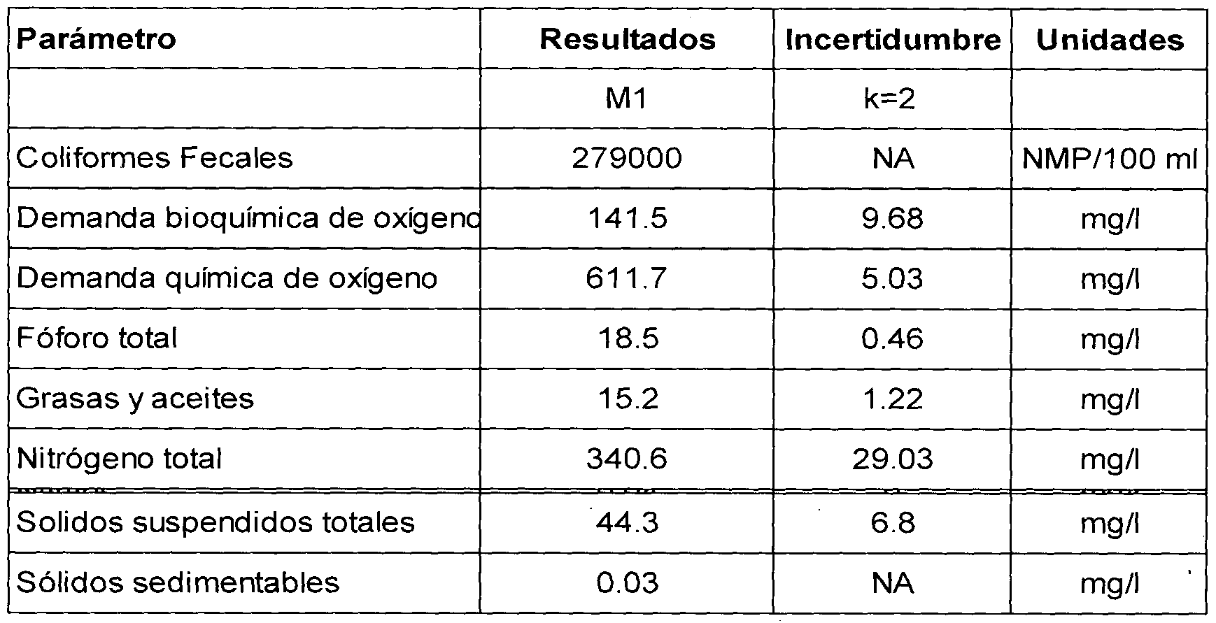
- Figure 9 shows Graphs of the results of the sampling of residual water, in a pilot test in a pig farm the "Intensive Livestock Treatment" was designed, in the reduction of fecal conformations in npm / 100 ml.
- Figure 10 shows the DB05 Biochemical Oxygen Demand at 5 days, measured in mg / l during the process
- Figure 1 1 shows the behavior of COD in mg / lt during process
- Figure 12 shows the decay of the total phosphorus concentration in mg / l during the process
- Figure 13 allows us to evaluate the efficiency of the equipment to separate fats and oils during the process
- Figure 14 shows the change in total nitrogen concentration in mg / l during the process
- Figure 15 shows the decrease in total suspended solids during the process.
- Figure 16 shows how literally sedimentable solids are virtually eliminated during the process.
- the present invention is composed of the following elements: A tank (1) where a basket type screen (2) is placed inside the tank.
- the tank has an influent feed (3) at the top and a discharge (4) at the bottom of the opposite face and is positioned so that there is a drop in the bottom of the tank, being lower on the opposite side to food.
- a removable sieve (2) is placed in the form of a basket to eliminate solid waste that could affect the operation of the plant, said removable sieve (2) is shaped like a basket and is supported on the upper edges of the tank, account with handles and hinges
- the removable screen (2) seen from the side has a trapezoidal shape whose longest side corresponds to the surface of the pond, its main face being adjacent to the face where the influent feed is located and on the opposite side it has an ascending side , so that the solids contained in the screen cannot block the passage of the liquid towards the discharge (4) and consequently to the other process equipment.
- the basket has been designed in such a way that it does not touch the bottom of the pond, thus allowing a better flow.
- the water treatment plant has a gravity flow distributor
- the gravity flow distributor (6) is a container whose objective is to distribute the flow evenly to other equipment, to avoid decantation and skimming. Its construction consists of a conical or concave bottom funnel-like body through which the water to be treated is fed through the feed pipe (7) and into an upper section (8) that is completely horizontal and on whose periphery the outputs at the same level (9) of the distributor that is completely horizontal, as are the distribution tubes to other equipment, maintaining an equal flow for each tube.
- the upper lateral part of the distributor can vary in shape depending on the application and can be circular, octagonal, or any other regular geometric shape, according to the number of equipment to which the flow is to be distributed, as long as it is not altered the characteristic of the conical or concave bottom and exit completely horizontal at the same level.
- This equipment also has a drain (10), for accumulated sludge.
- the distributor (6) feeds one or more decanter-bioreactor equipment (11) of vertical type (fig. 3).
- the biological treatment starts in anaerobic equipment to achieve greater peak absorption, lower energy requirement and lower sludge production
- the decanter - bioreactor (11) is a vessel consisting of a body divided into several sections.
- the upper part (12) is a truncated cone or vault, the truncated part or mouth of the container (19) being the suitable place to support a container or filter (13) and the corresponding container lid (14).
- the decanter also has in the upper part projections (16) in the form of a prism or arc, adjacent to the conical or domed section, these projections serve to give greater mechanical resistance to the container; the vertical face of one of the projections is used to place the horizontal feeding tube (15), while a vent or vent (17) is placed on the horizontal face of another of the projections.
- the middle part of the container is a cylinder or cylindrical trunk, while the lower part is divided into two sections; a section was shaped like a truncated inverted cone or vault (18) and a cylindrical shape with a flat base (33) at the end of truncation of the cone.
- the decanter - bioreactor has a feed tube (15), a reverse filter (13), a vent (17), a sludge extraction tube (23) and an outlet duct (20). ⁇ ⁇ ⁇ '
- the water to be treated can be fed by the upper part, if the feed is lateral, by the feed pipe (15) which is a tube consisting of two sections; the first horizontal section extends to the center of the decanter - bioreactor, crossing the filter and ending in a "T" where one of the arms of the "T” reaches almost to the cover (14) of the decanter, while the Another end of the "T” (22) extends vertically downward through the bottom of the container or filter (13), its length being less than the length of the cylindrical section of the container.
- the feed pipe which is a tube consisting of two sections; the first horizontal section extends to the center of the decanter - bioreactor, crossing the filter and ending in a "T" where one of the arms of the "T” reaches almost to the cover (14) of the decanter, while the Another end of the "T” (22) extends vertically downward through the bottom of the container or filter (13), its length being less than the length of the cylindrical section of the container.
- the container or filter (13) which is a truncated cone-shaped body, closed at the bottom where only the vertical section (22) of the tube passes through feed (15) to deposit the flow near the lower conical section of the decanter.
- the container (13) has at the bottom of the surface a series of holes (21) to allow the entry of: fluid into the container or filter (13) laterally, located on the periphery of the upper part of the filter; in a horizontal position, opposite to the feeding duct and at a height below the level of the feeding tube (15), is the discharge duct (20) whose diameter is smaller than the diameter of the feeding duct (15).
- the decanter-bioreactor (11) also has an inclined duct (23) or maintenance duct that runs from the top of the decanter through one of the projections (16) to the bottom of the lower section of the decanter.
- the maintenance duct (23) has a cover (25) at its upper end and a horizontal branch (24) that is located at a lower height than the feeding (15) and discharge (20) ducts, where the Bypass crosses the wall of the decanter (11) and at its free end has a valve (26) to allow cleaning of the system; additionally it has a vent (17) at the top in one of the projections (16) consisting of a duct to allow the exit of gases.
- This equipment can be fitted with an accelerated decanter (27) to speed up the process.
- the discharge duct (20) feeds an inverted anaerobic filter (28), (Fig. 6) whose outer geometry is equal to that of the decanter (11), having the same upper sections (29), cylindrical section (30), triangular projections (31), lower conical section (32), and lower cylindrical section (33b) but not necessarily the same capacity, volume or content.
- the anaerobic filter has a feed duct (34) that reaches the center of the filter, the feed can be made lateral or from the top, but the tube rests to the center of the bottom, at whose end it has a shaped termination of "T" (35) where one of the arms of the "T” extends almost to the cover (36) of the filter while the other arm of the "T” extends towards the bottom of the filter through the tank upper (37) and reaching the inside of the lower tank (38), the anaerobic filter (28) has an inverted truncated cone shaped tank (37) supported by the filter mouth; said tank is closed at its base and at the bottom of its periphery has a series of perforations (39), additionally the tank (37) has a landfill (40) that connects to the outlet duct (41).
- the filter also has a sludge extraction duct (42) consisting of an inclined tube that goes from the outside of the filter, going through one of the projections (31) and the lower tank (38) until it reaches the lower cylindrical section (33b), where the tube has a horizontal branch (24b). which is below the supply line (34) and below the discharge line (41); said bypass crosses the wall of the filter and at the end it has a bypass valve (26). Additionally, the anaerobic filter has one of the projections (31) with a vent (43).
- the water treatment plant may include another filter that, unlike the first filter, the second filter is aerobic (44).
- the aerobic filter is a tank with similar geometry to the previous ones and is composed of the same sections that are top (45) conical or upper concave section (46), projections or vaulted (47) cylindrical body (48), lower conical section ( 49) and lower cylindrical section (50).
- the aerobic filter (44) has a feeding duct (51) consisting of a horizontal tube that crosses the tank wall (44) and the wall of an inner upper container (52) to a central part, where it ends in a bypass T "(53).
- One end of the" T “(53) projects upward, while the other end pours the liquid into the container (52) that functions as a spout distributing the liquid through a series of holes (54) which are located at the bottom periphery of the wall of the container, to the contact material (55) inside the aerobic filter (44).
- a series of holes (54) which are located at the bottom periphery of the wall of the container, to the contact material (55) inside the aerobic filter (44).
- At the bottom, inside the aerobic filter is another container in truncated and inverted cone shape (56) that has a series of holes (57b) in the upper part of the periphery and in the lower part, to allow the passage of liquid and sludge inside, but not the passage of the contact material (55) .
- the filter may have a bubble aerator (58) fed through a pipe network by a blower (not shown).
- the treated water is extracted by a duct (59) with a pump or by level difference from the lower container (56).
- the duct (59) also has a pair of joints with start In the last sector. Placed in an inclined position and has a horizontal branch (63)
- the duct (59) is also located in the upper half of the cylindrical body of the aerobic filter in a lower position than the upper container (52).
- the aerobic filter (44) has a sludge extraction duct (60) consisting of a tube placed in an inclined position that extends from one of the projections (47) to the lower section (49); the pipeline has a flow valve (61); the horizontal bypass (62) is in a position below the height of the outlet of the treated liquid and below the feed pipe.
- the treated water is sent to a post treatment of the artificial wetland type (64) or an absorption well, or absorption field or a receiving body.
- The, or wastewater discharges are sent through a pipeline (3) to a tank (1) that has a sieve (2) as described the basket-shaped sieve, where the part of the bottom of the sieve touches the surface of the pond, while the other part is raised forming an inclined plane in the direction of the discharge tube (4), allowing the passage of the liquid and at the same time keeping the discharge of the liquid (4) that is free of obstruction at the bottom of the pond (1) and in a location opposite to the pond feed (3); once the large solids have been removed from the water, it passes to the flow distributor (6), as described above, from where it is distributed equally by pipes of the same cross-section or of the same diameter, to different decanter-bioreactor equipment.
- the liquid subsequently reaches a vertical type decanter-bioreactor (11) to process the mixture (more polluting water).
- the feeding pipe (15) crosses the wall of the equipment and the wall of a container (13) that is supported in the mouth of the decanter-bioreactor, until it reaches the center, of the equipment, where the feeding tube (15) has a "T" where one of the arms of the "T” is directed upwards until reaching the cover (14) and the other arm extends towards the bottom of the decanter-bioreactor (11) crossing the bottom of the container (13) without reaching the lower conical section, where it discharges.
- the geometry of the decanter-bioreactor (11) allows the fluid to enter into the equipment by directing the flow towards the conical bottom section (18).
- the conical lower section favors the collection of sludge since it works by gravity, keeping the concentrates and sludge in the lower cylindrical section (33) that acts as a collector.
- the fluid rises until it reaches the container (13) to which it enters through the holes (21) located perimeter in the lower area of the vessel wall (13) until it reaches the discharge duct (22) to extract digested sludge, or excess sludge, from where they will be sent to the next stage.
- the excess sludge extraction valve (26) located at the end of the branch (24) of the sludge discharge duct (23) is opened.
- the decanter - bioreactor has a vent (17) that allows it to release gases resulting from decomposition. In this same equipment an accelerated decanter (27) can be placed to improve the process.
- the discharge tube of the decanter-bioreactor connects with the feed pipe (34) of the anaerobic filter (28), which was previously described, where water enters through the top of the anaerobic filter (28) through the duct (34 ) that moves the center of the water to where there is a "T” (35) where one of the ends of the "T” is directed up to the cover (36) of the anaerobic filter, while the other arm of the "T” (35) is directed towards the bottom of the anaerobic filter (28), passing through the upper tank (37), discharging the fluid near the lower conical section (32), inside the lower tank (38), leaving the lower tank (38) by means of the perimeter perforations (39) located at the upper edge (38).
- the liquid crosses the upper perforations and ascends by density difference to the tank upper (37), and enters it through a series of holes (39) located perimeter in the lower edge of the upper tank (37); continuing its ascent until reaching the landfill (40) consisting of an open duct at the top, so that the water spills inside before leaving the anaerobic filter (28) through the outlet duct (41), being the landfill of great relevance because it allows the first aeration of water in the process of treatment.
- the perforations in the bottom tank at the bottom serve for the collection and movement of sludge.
- the inverted anaerobic filter (28) is conical or concave at the bottom, topped with a cylindrical shape (33b) to facilitate the accumulation of sludge by gravity, also allowing bioreaction or biofeedback by bringing the new material into contact with the biomass accumulated, concentrating the most dense at the bottom; It is important to mention that the diameter of the holes (39) is small enough to prevent the ingress of the filter material.
- the inverted anaerobic filter (28) has a sludge extraction system or cleaning duct (42) consisting of an inclined tube that reaches the bottom of the inverted anaerobic filter (28);
- the cleaning duct (42) has a horizontal bypass (24b) through which sludge can be removed by opening a bypass valve (26b) placed at the free end of the horizontal bypass taking advantage of the weight of the hydrostatic column and the position of the horizontal bypass of the cleaning duct that is below the height of the feed duct (34) and below the discharge duct (41), such that the liquid in the inverted anaerobic filter (28) exerts a pressure that favors the sludge outlet through the horizontal bypass of the cleaning duct (42).
- the last stage for water treatment consists of an aerobic filter (44), which was previously described, which, like the previous equipment, consists of a conical bottom container (50) where water enters through a pipeline supply (51) to the center of the filter where it has a "T" branch whose upper arm is oriented towards the cover (45) of the aerobic filter (44) through the upper tank (52) where the liquid is poured;
- the upper tank (52) has the function of being a landfill, receives the feed and distributes the water inside the filter through the holes (54) that are distributed perimeter in the lower section of the upper tank (52), producing a first aeration for the water inside the aerobic filter (44).
- the anaerobic filter (44) which can be fed from the bottom with a bubble aerator (58) fed by a blower (not shown) through a network of pipes to distribute the air over the entire transverse surface, achieving a backflow to achieve better absorption.
- the treated water enters the lower tank through the holes (57) and (57b) located both in the upper part and in the lower part of the wall of the lower tank (56); It is important to mention that the diameter of the holes is small enough to prevent the filtering material (55) from entering the holes, but prevents clogging.
- the solid material that manages to enter the lower tank (56) will be transferred to the bottom of the lower tank (56) and will fall by gravity to the bottom of the aerobic filter (44), being placed in the lower cylindrical section (50) from which it can be removed by the maintenance pipeline (60) or by pumping; in the same way as in the equipment described above.
- the output of the aerobic filter (44) is through an outlet duct (59), which takes the treated water from the top of the lower tank (56) to avoid dragging solids.
- the treatment plant may have a tank for contact with disinfectant or added material, or a disinfection system of any type (for example UV light).
- the sequence of the treatment plant is not necessarily one by one, it being possible to divide the flow into 5 bioreactor decanters (1 1) and join the effluent of these to feed two anaerobic filters (28) and subsequently feed one or several aerobic filters (44) or several depending on the quality of the influent and the required quality of the effluent. That is, the treatment plant can be in series or in parallel, combining the stages as necessary.
- Sample Type Waste water simple sample
- Sample Type Waste water simple sample
Landscapes
- Chemical & Material Sciences (AREA)
- Life Sciences & Earth Sciences (AREA)
- Chemical Kinetics & Catalysis (AREA)
- Engineering & Computer Science (AREA)
- Microbiology (AREA)
- Hydrology & Water Resources (AREA)
- Environmental & Geological Engineering (AREA)
- Water Supply & Treatment (AREA)
- Organic Chemistry (AREA)
- Biodiversity & Conservation Biology (AREA)
- General Chemical & Material Sciences (AREA)
- Oil, Petroleum & Natural Gas (AREA)
- Health & Medical Sciences (AREA)
- Molecular Biology (AREA)
- Biological Treatment Of Waste Water (AREA)
- Purification Treatments By Anaerobic Or Anaerobic And Aerobic Bacteria Or Animals (AREA)
- Sewage (AREA)
- Hydroponics (AREA)
- Removal Of Specific Substances (AREA)
- Treatment Of Biological Wastes In General (AREA)
Abstract
Description

Claims
Priority Applications (4)
| Application Number | Priority Date | Filing Date | Title |
|---|---|---|---|
| BR112013028394A BR112013028394A2 (pt) | 2011-05-13 | 2012-05-11 | usina modular para tratamento de águas residuais |
| US14/117,616 US9890067B2 (en) | 2011-05-13 | 2012-05-11 | Modular wastewater treatment plant |
| CA2835308A CA2835308C (en) | 2011-05-13 | 2012-05-11 | Modular wastewater treatment plant |
| EP12785004.8A EP2708515B1 (en) | 2011-05-13 | 2012-05-11 | Modular wastewater treatment plant |
Applications Claiming Priority (2)
| Application Number | Priority Date | Filing Date | Title |
|---|---|---|---|
| MXMX/A/2011/005080 | 2011-05-13 | ||
| MX2011005080A MX338620B (es) | 2011-05-13 | 2011-05-13 | Planta modular para tratamiento de aguas residuales. |
Publications (2)
| Publication Number | Publication Date |
|---|---|
| WO2012158012A2 true WO2012158012A2 (es) | 2012-11-22 |
| WO2012158012A3 WO2012158012A3 (es) | 2013-03-28 |
Family
ID=47177522
Family Applications (1)
| Application Number | Title | Priority Date | Filing Date |
|---|---|---|---|
| PCT/MX2012/000053 Ceased WO2012158012A2 (es) | 2011-05-13 | 2012-05-11 | Planta modular para tratamiento de aguas residuales |
Country Status (10)
| Country | Link |
|---|---|
| US (1) | US9890067B2 (es) |
| EP (1) | EP2708515B1 (es) |
| BR (1) | BR112013028394A2 (es) |
| CA (1) | CA2835308C (es) |
| CO (1) | CO6852055A2 (es) |
| CR (1) | CR20130595A (es) |
| GT (1) | GT201300271A (es) |
| MX (1) | MX338620B (es) |
| PE (1) | PE20140922A1 (es) |
| WO (1) | WO2012158012A2 (es) |
Cited By (3)
| Publication number | Priority date | Publication date | Assignee | Title |
|---|---|---|---|---|
| WO2014096877A1 (en) | 2012-12-20 | 2014-06-26 | Organica Technológiák Zártkörüen Müködö | Filter panel for the treatment of liquids, especially for disc wastewater filter equipment |
| US9890067B2 (en) | 2011-05-13 | 2018-02-13 | Jose Rogelio Perez Monsrreal | Modular wastewater treatment plant |
| WO2018025189A3 (es) * | 2016-08-02 | 2018-03-29 | Grupo Rotoplas, S.A.B. De C.V. | Biorreactor anaerobio |
Families Citing this family (15)
| Publication number | Priority date | Publication date | Assignee | Title |
|---|---|---|---|---|
| CN103214093B (zh) * | 2013-04-09 | 2014-07-02 | 东华大学 | 低c/n生活污水高效脱氮的复合电极水平潜流人工湿地装置 |
| MX364182B (es) * | 2013-07-11 | 2019-03-29 | Martin Munoz Cortes | Fosa septica mejorada, con sistema de filtrado de fluidos con expulsador de gases y extractor de sedimentos dual. |
| CN105858900A (zh) * | 2016-05-18 | 2016-08-17 | 东南大学 | 一种模块化格栅式组合人工湿地系统 |
| CN105858901A (zh) * | 2016-05-18 | 2016-08-17 | 东南大学 | 一种预加工插合式组合人工湿地系统 |
| CN106277562A (zh) * | 2016-07-27 | 2017-01-04 | 宁海逸航环保科技有限公司 | 一种新型农村污水处理的工艺流程和方法 |
| US9873607B1 (en) | 2016-07-28 | 2018-01-23 | John Wayen Midnight | Five-gallon water supply systems |
| CN107337312A (zh) * | 2017-07-19 | 2017-11-10 | 中科鼎实环境工程股份有限公司 | 模块化可组卸式人工湿地系统及其潜流人工湿地总成 |
| CN110255811B (zh) * | 2019-05-31 | 2021-12-14 | 浙江水利水电学院 | 一种分散式农村生活污水处理装置及方法 |
| CN111115835B (zh) * | 2020-01-15 | 2021-05-07 | 中国水利水电科学研究院 | 一种天然河道污水防治系统和方法及设计方法 |
| CN111253001A (zh) * | 2020-01-19 | 2020-06-09 | 泉州南京大学环保产业研究院 | 生活污水处理装置及其处理方法 |
| CN111995207A (zh) * | 2020-07-07 | 2020-11-27 | 河北鑫达菲塑料制品有限公司 | 一种无渗漏三格化粪池 |
| CN112023458B (zh) * | 2020-08-25 | 2021-10-29 | 长江勘测规划设计研究有限责任公司 | 基于双筒的竖流式沉淀池 |
| CN112678992B (zh) * | 2020-12-15 | 2021-08-13 | 吉林建筑大学 | 农田排水回用的方法 |
| CN113185068B (zh) * | 2021-06-10 | 2022-08-09 | 桂林理工大学 | 一种复合式有机废水处理系统 |
| CN115722016B (zh) * | 2022-11-30 | 2025-04-18 | 安徽鑫广环保科技有限公司 | 一种工业污染物的独立水洗处理装置及处理方法 |
Citations (3)
| Publication number | Priority date | Publication date | Assignee | Title |
|---|---|---|---|---|
| MX213398B (es) | 1998-12-08 | 2002-10-22 | Equipo de tratamiento de aguas residuales domesticas con extraccion de lodos | |
| MXYU05000003A (es) | 2005-02-22 | 2006-10-17 | Josérogelio Pérez Monsrreal | Equipo para tratar las aguas residuales de tipo doméstico con salida lenta de fluidos |
| MX2009001621A (es) | 2009-02-12 | 2010-08-12 | Jose Rogelio Perez Monsrreal | Tanque septico con filtro autolimpiable y con retroalimentacion para decantacion desnatacion. |
Family Cites Families (16)
| Publication number | Priority date | Publication date | Assignee | Title |
|---|---|---|---|---|
| GB521036A (en) | 1938-03-29 | 1940-05-09 | Joseph Darius Griffin | Improvements in sewage sludge digestion |
| US4614584A (en) * | 1985-02-11 | 1986-09-30 | Duca Mark B Di | Distributor box for septic tank systems |
| US4824563A (en) | 1985-12-04 | 1989-04-25 | Kabushiki Kaisha Meidensha | Equipment for treating waste water |
| HU9202203D0 (en) | 1990-01-29 | 1992-12-28 | Yasuyuki Sakurada | Apparatus for purifying sewage water |
| US5531894A (en) | 1993-11-18 | 1996-07-02 | Orenco Systems, Inc. | Method of treating wastewater |
| US5705057A (en) | 1996-03-25 | 1998-01-06 | Hoffa; Gary | Fluidized bed biological filter assembly for fish tanks |
| FR2775279B1 (fr) | 1998-02-20 | 2000-04-14 | Eparco Sa | Installation et procede specialement destines au traitement des effluents viti-vinicoles |
| US6319396B1 (en) | 1998-05-19 | 2001-11-20 | Robert F. Heagey | Clarifier cone for filtering and separating solids from solution |
| CN2356028Y (zh) | 1999-01-22 | 1999-12-29 | 刘端华 | 多生物量生物反应器 |
| JP2001079576A (ja) | 1999-09-17 | 2001-03-27 | Kubota Corp | 浄化槽 |
| US6682654B1 (en) | 2000-08-11 | 2004-01-27 | Steve E. Telchuk | Sludge recovery apparatus and method |
| US7297274B2 (en) | 2001-10-24 | 2007-11-20 | University Of Florida Research Foundation, Inc. | Fixed-film anaerobic digestion of flushed waste |
| WO2006091064A1 (es) | 2005-02-22 | 2006-08-31 | Perez Monsrreal Jose Rogelio | Equipo para tratar las aguas residuales de tipo doméstico con salida lenta de fluidos |
| SV2008002974A (es) | 2008-07-03 | 2011-08-11 | Larin Carlos Antonio Barillas | Sistema de tratamiento y descontaminacion de agua de desecho domestico |
| TWI568687B (zh) * | 2009-06-15 | 2017-02-01 | 沙烏地阿拉伯油品公司 | 包含懸浮系統與多重生物反應器區域的經懸浮介質膜生物反應器系統及方法 |
| MX338620B (es) | 2011-05-13 | 2016-03-22 | José Rogelio Pérez Monsrreal | Planta modular para tratamiento de aguas residuales. |
-
2011
- 2011-05-13 MX MX2011005080A patent/MX338620B/es active IP Right Grant
-
2012
- 2012-05-11 CA CA2835308A patent/CA2835308C/en not_active Expired - Fee Related
- 2012-05-11 PE PE2013002475A patent/PE20140922A1/es not_active Application Discontinuation
- 2012-05-11 US US14/117,616 patent/US9890067B2/en not_active Expired - Fee Related
- 2012-05-11 BR BR112013028394A patent/BR112013028394A2/pt not_active Application Discontinuation
- 2012-05-11 WO PCT/MX2012/000053 patent/WO2012158012A2/es not_active Ceased
- 2012-05-11 EP EP12785004.8A patent/EP2708515B1/en not_active Not-in-force
-
2013
- 2013-11-08 GT GT201300271A patent/GT201300271A/es unknown
- 2013-11-13 CO CO13267076A patent/CO6852055A2/es unknown
- 2013-11-14 CR CR20130595A patent/CR20130595A/es unknown
Patent Citations (3)
| Publication number | Priority date | Publication date | Assignee | Title |
|---|---|---|---|---|
| MX213398B (es) | 1998-12-08 | 2002-10-22 | Equipo de tratamiento de aguas residuales domesticas con extraccion de lodos | |
| MXYU05000003A (es) | 2005-02-22 | 2006-10-17 | Josérogelio Pérez Monsrreal | Equipo para tratar las aguas residuales de tipo doméstico con salida lenta de fluidos |
| MX2009001621A (es) | 2009-02-12 | 2010-08-12 | Jose Rogelio Perez Monsrreal | Tanque septico con filtro autolimpiable y con retroalimentacion para decantacion desnatacion. |
Cited By (3)
| Publication number | Priority date | Publication date | Assignee | Title |
|---|---|---|---|---|
| US9890067B2 (en) | 2011-05-13 | 2018-02-13 | Jose Rogelio Perez Monsrreal | Modular wastewater treatment plant |
| WO2014096877A1 (en) | 2012-12-20 | 2014-06-26 | Organica Technológiák Zártkörüen Müködö | Filter panel for the treatment of liquids, especially for disc wastewater filter equipment |
| WO2018025189A3 (es) * | 2016-08-02 | 2018-03-29 | Grupo Rotoplas, S.A.B. De C.V. | Biorreactor anaerobio |
Also Published As
| Publication number | Publication date |
|---|---|
| CA2835308A1 (en) | 2012-11-22 |
| MX338620B (es) | 2016-03-22 |
| CO6852055A2 (es) | 2014-01-30 |
| WO2012158012A3 (es) | 2013-03-28 |
| CR20130595A (es) | 2014-01-14 |
| US20150014245A1 (en) | 2015-01-15 |
| EP2708515A4 (en) | 2014-11-12 |
| US9890067B2 (en) | 2018-02-13 |
| MX2011005080A (es) | 2012-11-19 |
| GT201300271A (es) | 2014-08-27 |
| EP2708515B1 (en) | 2019-03-20 |
| EP2708515A2 (en) | 2014-03-19 |
| CA2835308C (en) | 2016-06-21 |
| PE20140922A1 (es) | 2014-08-13 |
| BR112013028394A2 (pt) | 2017-01-24 |
Similar Documents
| Publication | Publication Date | Title |
|---|---|---|
| WO2012158012A2 (es) | Planta modular para tratamiento de aguas residuales | |
| CN101811800B (zh) | 一种生活污水处理装置 | |
| WO2013129901A1 (es) | Bioreactor combinado para el tratamiento de aguas residuales, mediante procesos anaerobios, aerobios y anoxicos de degradación de materia orgánica con sistema separador de zonas y captación de biogás, natas y lodos | |
| HUE030155T2 (en) | Biological wastewater treatment plant with increased efficiency | |
| NO330681B1 (no) | Oppdrettssystem for akvatiske organismer | |
| ES2691042T3 (es) | Biofiltro para digestión de aguas residuales | |
| CN108862821A (zh) | 双级免曝气无回流的生活污水处理系统 | |
| WO2012016347A1 (es) | Sistema y proceso sbr de tratamiento de aguas servidas de volumen limitado | |
| CN119019060B (zh) | 一种污水处理系统及污水处理方法 | |
| CN105601054A (zh) | 一种农村生活养殖混合污水处理集成系统 | |
| CN101863546B (zh) | 多级斜管或斜板沉淀池 | |
| CN201458913U (zh) | 一种一体化生物生态协同污水处理反应器 | |
| CN209428340U (zh) | 庭院式污水处理一体化设备 | |
| CN103991957B (zh) | 一体化污水处理装置 | |
| CN209259878U (zh) | 一种拼装式污水净化装置 | |
| CN111825211A (zh) | 一种一体化单户生活污水净化装置 | |
| CN100351187C (zh) | 污泥厌氧消化方法和消化器 | |
| CN206109135U (zh) | 一种农村生活养殖混合污水处理集成系统 | |
| CN212065388U (zh) | 流水养殖水体中悬浮颗粒物净化装置 | |
| WO2018025189A2 (es) | Biorreactor anaerobio | |
| CN211394192U (zh) | 一种与人工湿地结合的立式农村污水处理设备 | |
| CN209428339U (zh) | 一种污水处理一体化设备 | |
| CN208717090U (zh) | 双级免曝气无回流的生活污水处理系统 | |
| CN108455798B (zh) | 一种地埋式医疗污水处理装置 | |
| CN106542705A (zh) | 一种农家乐污水处理装置及方法 |
Legal Events
| Date | Code | Title | Description |
|---|---|---|---|
| ENP | Entry into the national phase |
Ref document number: 2835308 Country of ref document: CA |
|
| WWE | Wipo information: entry into national phase |
Ref document number: 002475-2013 Country of ref document: PE |
|
| NENP | Non-entry into the national phase |
Ref country code: DE |
|
| WWE | Wipo information: entry into national phase |
Ref document number: 13267076 Country of ref document: CO |
|
| WWE | Wipo information: entry into national phase |
Ref document number: CR2013-000595 Country of ref document: CR |
|
| WWE | Wipo information: entry into national phase |
Ref document number: 2012785004 Country of ref document: EP |
|
| REG | Reference to national code |
Ref country code: BR Ref legal event code: B01A Ref document number: 112013028394 Country of ref document: BR |
|
| WWE | Wipo information: entry into national phase |
Ref document number: 14117616 Country of ref document: US |
|
| ENP | Entry into the national phase |
Ref document number: 112013028394 Country of ref document: BR Kind code of ref document: A2 Effective date: 20131104 |