WO2012160621A1 - 流体制御システム - Google Patents
流体制御システム Download PDFInfo
- Publication number
- WO2012160621A1 WO2012160621A1 PCT/JP2011/061646 JP2011061646W WO2012160621A1 WO 2012160621 A1 WO2012160621 A1 WO 2012160621A1 JP 2011061646 W JP2011061646 W JP 2011061646W WO 2012160621 A1 WO2012160621 A1 WO 2012160621A1
- Authority
- WO
- WIPO (PCT)
- Prior art keywords
- fluid
- valve
- flow
- thermostat
- coolant
- Prior art date
- Legal status (The legal status is an assumption and is not a legal conclusion. Google has not performed a legal analysis and makes no representation as to the accuracy of the status listed.)
- Ceased
Links
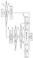
Images



Classifications
-
- F—MECHANICAL ENGINEERING; LIGHTING; HEATING; WEAPONS; BLASTING
- F01—MACHINES OR ENGINES IN GENERAL; ENGINE PLANTS IN GENERAL; STEAM ENGINES
- F01P—COOLING OF MACHINES OR ENGINES IN GENERAL; COOLING OF INTERNAL-COMBUSTION ENGINES
- F01P7/00—Controlling of coolant flow
- F01P7/14—Controlling of coolant flow the coolant being liquid
- F01P7/16—Controlling of coolant flow the coolant being liquid by thermostatic control
-
- F—MECHANICAL ENGINEERING; LIGHTING; HEATING; WEAPONS; BLASTING
- F01—MACHINES OR ENGINES IN GENERAL; ENGINE PLANTS IN GENERAL; STEAM ENGINES
- F01P—COOLING OF MACHINES OR ENGINES IN GENERAL; COOLING OF INTERNAL-COMBUSTION ENGINES
- F01P7/00—Controlling of coolant flow
- F01P7/14—Controlling of coolant flow the coolant being liquid
-
- F—MECHANICAL ENGINEERING; LIGHTING; HEATING; WEAPONS; BLASTING
- F01—MACHINES OR ENGINES IN GENERAL; ENGINE PLANTS IN GENERAL; STEAM ENGINES
- F01P—COOLING OF MACHINES OR ENGINES IN GENERAL; COOLING OF INTERNAL-COMBUSTION ENGINES
- F01P7/00—Controlling of coolant flow
- F01P7/14—Controlling of coolant flow the coolant being liquid
- F01P7/16—Controlling of coolant flow the coolant being liquid by thermostatic control
- F01P7/165—Controlling of coolant flow the coolant being liquid by thermostatic control characterised by systems with two or more loops
-
- F—MECHANICAL ENGINEERING; LIGHTING; HEATING; WEAPONS; BLASTING
- F01—MACHINES OR ENGINES IN GENERAL; ENGINE PLANTS IN GENERAL; STEAM ENGINES
- F01P—COOLING OF MACHINES OR ENGINES IN GENERAL; COOLING OF INTERNAL-COMBUSTION ENGINES
- F01P3/00—Liquid cooling
- F01P3/02—Arrangements for cooling cylinders or cylinder heads
- F01P2003/028—Cooling cylinders and cylinder heads in series
-
- F—MECHANICAL ENGINEERING; LIGHTING; HEATING; WEAPONS; BLASTING
- F01—MACHINES OR ENGINES IN GENERAL; ENGINE PLANTS IN GENERAL; STEAM ENGINES
- F01P—COOLING OF MACHINES OR ENGINES IN GENERAL; COOLING OF INTERNAL-COMBUSTION ENGINES
- F01P2031/00—Fail safe
- F01P2031/32—Deblocking of damaged thermostat
-
- Y—GENERAL TAGGING OF NEW TECHNOLOGICAL DEVELOPMENTS; GENERAL TAGGING OF CROSS-SECTIONAL TECHNOLOGIES SPANNING OVER SEVERAL SECTIONS OF THE IPC; TECHNICAL SUBJECTS COVERED BY FORMER USPC CROSS-REFERENCE ART COLLECTIONS [XRACs] AND DIGESTS
- Y10—TECHNICAL SUBJECTS COVERED BY FORMER USPC
- Y10T—TECHNICAL SUBJECTS COVERED BY FORMER US CLASSIFICATION
- Y10T137/00—Fluid handling
- Y10T137/6416—With heating or cooling of the system
-
- Y—GENERAL TAGGING OF NEW TECHNOLOGICAL DEVELOPMENTS; GENERAL TAGGING OF CROSS-SECTIONAL TECHNOLOGIES SPANNING OVER SEVERAL SECTIONS OF THE IPC; TECHNICAL SUBJECTS COVERED BY FORMER USPC CROSS-REFERENCE ART COLLECTIONS [XRACs] AND DIGESTS
- Y10—TECHNICAL SUBJECTS COVERED BY FORMER USPC
- Y10T—TECHNICAL SUBJECTS COVERED BY FORMER US CLASSIFICATION
- Y10T137/00—Fluid handling
- Y10T137/8593—Systems
- Y10T137/86493—Multi-way valve unit
Definitions
- the present invention relates to a fluid control system.
- Patent Document 1 discloses a technique that is considered to be related to the present invention in terms of configuration as a technique for controlling a fluid such as engine coolant.
- Patent Document 1 discloses a cooling device for an internal combustion engine in which a high water temperature and a low water temperature are set by a high temperature thermo valve and a low temperature thermo valve.
- Patent Documents 2 to 4 disclose techniques relating to a thermostat failure.
- Patent Document 2 discloses an engine cooling system failure detection device that detects a thermostat failure.
- Patent Document 3 discloses a cooling control system for an internal combustion engine that circulates a cooling medium in a circulation path provided with a heat exchanger that dissipates heat when a failure occurs in a thermostat valve.
- Patent Document 4 an engine having an electric thermostat that opens and closes according to the temperature of the cooling water by opening and closing according to the higher one of the temperature of the cooling water and the temperature of the electric heater, even if the electric heater fails.
- a cooling device is disclosed.
- a thermostat can be provided to properly cool the object to be cooled.
- the following can be performed when the object to be cooled is cooled using a thermostat. That is, the first and second branch paths that merge after branching in the fluid supply path that supplies the fluid to be cooled can be provided, and a thermostat can be provided in at least one of these branch paths.
- a thermostat can be provided in at least one of these branch paths.
- the present invention enables the fluid flow control by each thermostat to be switched between valid and invalid of the fluid flow control by at least one of the thermostats provided in each of the branch paths that merge after branching.
- An object of the present invention is to provide a fluid control system that can suppress the deterioration of the cooling state of a supply target even if one of the thermostats is open or closed when it can be performed. .
- the present invention includes a first thermostat in the first branch path out of the first and second branch paths that merge after branching, and the second branch path is more open than the first thermostat.
- a thermostat unit comprising a second thermostat set at a low temperature, a first part of the first branch path that is downstream from the first thermostat, and the second branch path Among the fluid supply paths that include a second part that is a part downstream of the second thermostat and the first and second branch paths and that supply fluid to a supply target, Among the first part and the third part that is the part after the second branch path merge, at least the valve part provided with a valve mechanism in the second part, and the first and second thermostats, The valve mechanism provided in the valve unit in a state in which one of the thermostats is in an open failure in which the valve remains open and a closed failure in which the thermostat remains closed A control unit that controls the valve unit so as to switch a flow control state of at least one of the valve mechanisms.
- the control unit when one of the first and second thermostats has a closed failure, has at least one of the valve mechanisms included in the valve unit.
- the valve portion By controlling the valve portion so as to switch the flow control state, the valve portion can be controlled so as to increase the flow rate of the fluid flowing through the other thermostat.
- the valve unit restricts the flow of fluid through at least the second branch path, and can supply the fluid to the supply target through the first branch path among the fluid supply paths.
- the first thermostat has a closed failure in a state where flow of fluid via the second branch path is restricted while flow of fluid via the high temperature side supply path is not restricted.
- the flow rate of the fluid flowing through the second thermostat is increased by controlling the valve unit so that the control unit releases at least the flow restriction of the fluid through the second branch path. It can be set as the structure made to do.
- the present invention relates to a cooler that cools the fluid flowing upstream of the first and second branch paths, and the cooler in a portion of the second branch path that is downstream of the second thermostat.
- the bypass path for circulating the fluid bypassing the second thermostat and the second thermostat are mechanically interlocked to communicate with the bypass path in a state where the second thermostat is closed.
- a valve mechanism is provided in a portion downstream of the bypass valve, and the valve portion releases at least the fluid flow restriction via the second branch path, Of the fluid supply paths, the second thermostat is closed in a state where the restriction of fluid flow via the low temperature side supply path capable of supplying the fluid to the supply target via the second branch path is released. Fluid that flows through the first thermostat by controlling the valve unit so that the control unit restricts the flow of the fluid through at least the second branch path when there is a failure. The flow rate can be increased.
- the present invention may be configured such that the valve unit includes a valve mechanism in two parts including the second part among the first, second and third parts.
- the control unit when one of the first and second thermostats has an open failure, the control unit has at least one of the valve mechanisms included in the valve unit. By controlling the valve unit so as to switch the flow control state, the valve unit can be controlled so as to reduce the flow rate of the fluid flowing through the third portion.
- the valve part includes a valve mechanism in two or more parts including at least the second part among the first, second and third parts, and the valve part is included in the fluid supply path.
- the flow restriction of the fluid via the high temperature side supply path capable of supplying the fluid to the supply target via the first branch path is released, and the flow of the fluid via the second branch path is restricted.
- the control unit controls the valve unit so as to restrict the flow of fluid through at least the high temperature side supply path, It can be set as the structure which reduces the flow volume of the fluid which distribute
- the present invention supplies the fluid to the supply target via the second branch path out of the fluid supply paths by releasing the flow restriction of the fluid via at least the second branch path.
- the control unit supplies the fluid through the second branch path.
- the valve portion includes a uniaxial rotary valve body disposed in two portions including the second portion of the first, second, and third portions. Of the second and third parts, two parts including the second part may be provided with valve mechanisms, respectively.
- the flow control of the fluid by each thermostat is performed by switching the flow control of the fluid by at least one of the thermostats. Even when one of the thermostats is open or closed, it is possible to suppress the deterioration of the cooling state of the supply target.
- FIG.3 (a) is a figure which shows a rotary valve body by a side view.
- FIG.3 (b) is a figure which shows a rotary valve body by the arrow A shown to Fig.3 (a).
- FIG. 4A is a view showing the rotary valve body in the section AA shown in FIG.
- FIG. 4B is a view showing the rotary valve body in the BB cross section shown in FIG.
- FIG. 4C is a view showing the rotary valve body in the CC section shown in FIG. It is a figure which shows a fluid supply path
- FIG. 8A is a diagram illustrating an example of a temperature change based on the first control operation when the first thermostat has a closed failure.
- FIG. 8B is a diagram illustrating an example of a temperature change based on the first control operation when the first and second thermostats are normal.
- FIG. 10A is a diagram showing an example of a temperature change based on the second control operation when the second thermostat has a closed failure.
- FIG. 10B is a diagram showing an example of a temperature change based on the second control operation when the first and second thermostats are normal.
- FIG. 12A is a diagram showing an example of a temperature change based on the third control operation when the first thermostat has an open failure, and shows a case where the valve unit is controlled when the temperature exceeds a predetermined value.
- FIG. 12B is a diagram illustrating an example of a temperature change based on the third control operation when the first thermostat has an open failure, and is a diagram illustrating a case where the valve unit is controlled when a predetermined time has elapsed. is there. It is a figure which shows a 4th control operation with a flowchart. It is a figure which shows an example of the temperature change based on 4th control action when a 2nd thermostat carries out an open failure.
- FIG. 1 is a schematic configuration diagram of an engine cooling circuit (hereinafter referred to as a cooling circuit) 100.
- the cooling circuit 100 includes a water pump (hereinafter referred to as W / P) 1, an engine 2, an oil cooler 3, a heater 4, an ATF (Automatic Transmission Transmission) warmer 5, a radiator 6, and an electronic control throttle 7.
- W / P water pump
- the rotary valve 10 is provided.
- the cooling circuit 100 is mounted on a vehicle (not shown).
- W / P1 circulates the coolant of the engine 2 that is a fluid.
- W / P 1 is a mechanical pump that is driven by the output of the engine 2.
- W / P1 may be an electrically driven pump.
- the coolant discharged from the W / P 1 flows into the engine 2 and the electronic control throttle 7 through the rotary valve 10.
- the coolant flows out of the rotary valve 10 through the outlet portions Out 1 and Out 2. Further, when flowing into the electronic control throttle 7, the coolant flows out of the rotary valve 10 via the outlet portion OutA.
- the engine 2 includes a cylinder block 2a and a cylinder head 2b.
- the engine 2 is provided with the following cooling passages. That is, the coolant flowing in from the outlet portion Out1 is circulated in the order of the cylinder block 2a and the cylinder head 2b, and the coolant flowing in from the outlet portion Out2 is circulated to the cylinder head 2b, and these are further merged by the cylinder head 2b. After that, a cooling passage is provided through which the combined coolant flows out from the cylinder head 2b.
- the oil cooler 3 exchanges heat between the lubricating oil of the engine 2 and the coolant to cool the lubricating oil.
- the heater 4 exchanges heat between the air and the coolant to heat the air.
- the heated air is used for heating the passenger compartment.
- the ATF warmer 5 exchanges heat between the ATF and the coolant to heat the ATF.
- the radiator 6 is a cooler, and cools the coolant by exchanging heat between the air and the coolant.
- a distribution path for distributing the oil cooler 3, the heater 4 and the ATF warmer 5 is a first radiator bypass path P ⁇ b> 11 that bypasses the radiator 6.
- the coolant flowing into the electronic control throttle 7 flows through the electronic control throttle 7 and then joins the first radiator bypass path P11.
- a coolant can be circulated through the electronic control throttle 7 in order to prevent the occurrence of malfunction due to freezing.
- a distribution path for distributing the electronic control throttle 7 is an engine bypass path P2 for bypassing the engine 2.
- the cooling circuit 100 a part of the coolant that has passed through the engine 2 flows into the rotary valve 10 via the inlet portion In3.
- This distribution path is a second radiator bypass path P12 that bypasses the radiator 6. Therefore, the coolant flowing through the first radiator bypass path P11 flows into the rotary valve 10 through the inlet portion In1. In addition, the coolant flowing through the second radiator bypass path P12 flows through the inlet portion In3.
- FIG. 2 is a schematic configuration diagram of the rotary valve 10.
- W / P 1 is also shown together with the rotary valve 10.
- the rotary valve 10 includes a first passage portion 11, a second passage portion 12, a rotary valve body 13, a drive portion 14, a valve body bypass passage portion 15, 1 bypass valve 16, detector 17, first thermostat 18, second thermostat 19, second bypass valve 20, and check valve 21.
- the check valve 21 is not shown for the sake of illustration.
- the first passage portion 11 is provided between the coolant outlet portion of the W / P 1 and the engine 2 and distributes the coolant.
- path part 12 is provided between the coolant inlet_port
- the passage portions 11 and 12 are arranged side by side.
- the passage portions 11 and 12 are connected to W / P1 at the ends in a state where they are arranged side by side.
- the first passage portion 11 is connected to the coolant outlet portion of the pump 1, and the second passage portion 12 is connected to the coolant inlet portion of the pump 1.
- the W / P1 side is the upstream side
- the second passage portion 12 is the W / P1 side is the downstream side.
- the first passage portion 11 communicates with the outlet portions Out1 and Out2 on the downstream side of the rotary valve body 13, and communicates with the outlet portion OutA on the upstream side of the rotary valve body 13. Therefore, the outlet portions Out1 and Out2 allow the coolant to flow out from the downstream portion of the rotary valve body 13 in the first passage portion 11. Further, the outlet portion OutA causes the coolant to flow out from the upstream portion of the rotary valve body 13 in the first passage portion 11.
- the second passage portion 12 communicates with the inlet portion In1 on the upstream side and the downstream side of the rotary valve body 13. Accordingly, the inlet portion In1 allows the coolant to flow into the upstream portion and the downstream portion of the second passage portion 12 with respect to the rotary valve body 13.
- the state in which the inlet portion In1 and the upstream side and the downstream side of the second passage portion 12 communicate with each other is not shown in FIG.
- the second passage portion 12 communicates with the inlet portion In2 on the upstream side and the downstream side of the rotary valve body 13. Therefore, the inlet portion In ⁇ b> 2 allows the coolant to flow through the second passage portion 12 to the upstream portion and the downstream portion of the rotary valve body 13.
- the second passage portion 12 includes a first communication portion B1 that communicates a portion downstream of the rotary valve body 13 and the inlet portion In2, and a portion upstream of the rotary valve body 13 and the inlet portion In2. And a second communication part B2 that communicates with each other.
- the second passage portion 12 further communicates with the inlet portion In3 on the upstream side of the rotary valve body 13.
- the rotary valve body 13 is provided so as to be interposed between the first passage portion 11 and the second passage portion 12.
- the rotary valve body 13 changes the circulation of the coolant flowing through the first passage portion 11 and the circulation of the coolant flowing through the second passage portion 12 by a rotating operation.
- the rotary valve body 13 prohibits and permits the circulation of the coolant flowing through the first passage portion 11 and the circulation of the coolant flowing through the second passage portion 12. It can be performed.
- the drive unit 14 includes an actuator 14 a and a gear box unit 14 b and drives the rotary valve body 13.
- the actuator 14a is specifically an electric motor.
- the valve body bypass passage portion 15 communicates the upstream portion and the downstream portion of the first passage portion 11 with respect to the rotary valve body 13.
- the first bypass valve 16 is a differential pressure valve, and in the first passage portion 11, the coolant pressure (upstream pressure) in the upstream portion of the rotary valve body 13 and the downstream of the rotary valve body 13.
- the flow of the coolant via the valve body bypass passage 15 is restricted and the restriction is released according to the pressure difference with the coolant pressure (downstream pressure) at the side portion (specifically, prohibited or permitted here) )I do.
- the first bypass valve 16 is cooled via the valve body bypass passage portion 15 when the magnitude of the differential pressure obtained by subtracting the downstream pressure from the upstream pressure is equal to or less than a predetermined magnitude.
- the flow of the liquid is prohibited, and the flow of the coolant through the valve body bypass passage portion 15 is permitted when the flow is higher than a predetermined size.
- the predetermined magnitude can be set larger than the magnitude of the maximum differential pressure obtained in the normal case.
- the first bypass valve 16 is further configured to operate mechanically in conjunction with the first thermostat 18.
- the first thermostat 18 is provided with an operating shaft 18 a connected to the first bypass valve 16 by extending so as to be interposed in the passage portions 11 and 12.
- the first bypass valve 16 allows the operating shaft 18a to drive the first bypass valve 16 so that the coolant flows through the valve body bypass passage portion 15 with the first thermostat 18 closed. While permitting, the flow of the coolant through the valve body bypass passage portion 15 is prohibited with the first thermostat 18 opened.
- the first bypass valve 16 In order to configure the first bypass valve 16 to be a differential pressure valve and to operate mechanically in conjunction with the first thermostat 18, for example, the first bypass valve 16 is opened with a differential pressure. While providing the structure, the entire first bypass valve 16 can be configured to operate mechanically in conjunction with the first thermostat 18.
- Detecting unit 17 is provided for the drive shaft of actuator 14a.
- the detector 17 detects the rotation angle of the drive shaft of the actuator 14a.
- the detection unit 17 may be provided, for example, with respect to the rotation shaft of the rotary valve body 13.
- the first thermostat 18 is provided in the first communication part B1.
- the second thermostat 19 is provided in the second communication part B2. Therefore, the second passage portion 12 communicates with the inlet portion In2 via the first thermostat 18 on the downstream side of the rotary valve body 13. As a result, it communicates with the radiator 6 via the first thermostat 18 on the downstream side of the rotary valve body 13.
- the second passage portion 12 communicates with the inlet portion In ⁇ b> 2 via the second thermostat 19 on the upstream side of the rotary valve body 13. As a result, the upstream side of the rotary valve body 13 communicates with the radiator 6 via the second thermostat 19.
- the valve opening temperatures of the thermostats 18 and 19 are different from each other.
- the valve opening temperature of the second thermostat 19 is set lower than the valve opening temperature of the first thermostat 18.
- the first thermostat 18 opens when the temperature of the coolant is higher than the predetermined value A, and closes when the temperature of the coolant is equal to or lower than the predetermined value A.
- the second thermostat 19 opens when the temperature of the coolant is higher than a predetermined value B, which is smaller than the predetermined value A, and closes when the temperature is lower than the predetermined value B.
- the second bypass valve 20 is provided so as to communicate and block the inlet portion In3.
- the second bypass valve 20 is configured to operate mechanically in conjunction with the second thermostat 19. Specifically, the second bypass valve 20 is connected to an operating shaft (not shown) of the second thermostat 19.
- the second bypass valve 20 allows the coolant to flow through the inlet portion In3 (that is, the second radiator bypass path P12) with the second thermostat 19 closed, and the second thermostat 19 In a state where the valve is opened, the flow of the coolant through the inlet portion In3 is prohibited.
- the check valve 21 controls the flow of the coolant flowing in from the inlet portion In1. Specifically, the check valve 21 permits the flow from the upstream side to the downstream side when the coolant flowing in from the inlet portion In1 flows into the upstream side and the downstream side of the second passage portion 12, and from the downstream side. Distributing upstream is prohibited.
- FIG. 3A is a diagram showing the rotary valve body 13 in a side view.
- FIG. 3B is a view showing the rotary valve body 13 as indicated by an arrow A shown in FIG. 4A is an AA cross section shown in FIG. 3A,
- FIG. 4B is a BB cross section shown in FIG. 3A, and
- FIG. 4C is FIG. 3A. It is a figure which shows the rotary valve body 13 in CC section shown.
- the rotary valve body 13 includes a first valve body portion R1 disposed in the first passage portion 11 and a second valve body portion R2 disposed in the second passage portion 12.
- the valve body portions R1 and R2 are both members having a hollow inside. In this respect, the insides of the valve body portions R1 and R2 do not communicate with each other.
- the first valve body R1 is provided with a first opening G1
- the second valve body R2 is provided with a second opening G2.
- the openings G1 and G2 are provided with different phases.
- the first opening G1 is a part combining the two opening parts divided by the column
- the second opening G2 is a part combining the three opening parts divided by the column.
- the first opening G1 can allow the coolant to flow to the engine 2 in a state where the first opening G1 is opened upstream and downstream of the first passage portion 11. Further, it is possible to prohibit the circulation of the coolant to the engine 2 in a state where only one of the upstream side and the downstream side of the first passage portion 11 is open.
- the first opening G ⁇ b> 1 is open to the upstream side and the downstream side of the first passage portion 11, and the flow rate of the coolant flowing through the engine 2 can be adjusted according to the phase of the rotary valve body 13.
- the second opening G2 can be allowed to flow through the second opening G2 with the second opening G2 opened to the upstream side and the downstream side of the second passage portion 12. In addition, it is possible to prohibit the flow of the coolant through the second opening G2 in a state where only one of the upstream side and the downstream side of the second passage portion 12 is open.
- the second valve body R2 is further provided with a third opening G3.
- the third opening G3 is provided at a position different from the second opening G2 in the axial direction.
- the third opening G3 is a second opening when the second opening G2 is located on the downstream side of the second passage portion 12 with the second opening G2 opening on the upstream side and the downstream side of the second passage portion 12. It is provided so as to open downstream of the passage portion 12.
- the second opening G2 is open on the upstream side and the downstream side of the second passage portion 12 and is located on the upstream side of the second passage portion 12, the second passage portion 12 It is provided so as not to open upstream.
- the coolant when the third opening G3 is located on the downstream side of the second passage portion 12, the coolant can be allowed to flow through the third opening G3. At this time, the coolant can be allowed to flow through the openings G2 and G3. On the other hand, when the third opening G3 is located on the upstream side of the second passage portion 12, the flow of the coolant through the third opening G3 can be prohibited. At this time, the circulation of the coolant through the second opening G2 out of the openings G2 and G3 can be permitted.
- the second opening G2 is opened on the upstream side and the downstream side of the second passage part 12, and the rotary valve body
- the flow rate of the coolant flowing from the upstream side to the downstream side of the second passage portion 12 with the rotary valve body 13 interposed therebetween can be gradually increased or decreased in accordance with the phase 13.
- the opening portions G2 and G3 are opened to the upstream side and the downstream side of the second passage portion 12, and the rotary valve Depending on the phase of the body 13, the flow rate of the coolant flowing from the upstream side to the downstream side of the second passage portion 12 with the rotary valve body 13 interposed therebetween can be gradually increased or decreased.
- the rotary valve body 13 configured in this way can simultaneously control the circulation of the coolant in the first passage portion 11 and the circulation of the coolant in the second passage portion 12 by a rotating operation.
- the rotary valve body 13 cancels the restriction on the flow of the coolant from the upstream side to the downstream side of the first passage portion 11 with the rotary valve body 13 sandwiched by the first valve body portion R1 ( At the same time, the flow of the coolant from the upstream side to the downstream side of the second passage portion 12 with the rotary valve body 13 sandwiched by the second valve body portion R2 is restricted (specifically, permitted here). Can be prohibited here).
- the restriction on the flow of the coolant from the upstream side to the downstream side of the first passage portion 11 with the rotary valve body 13 sandwiched between the first valve body portion R1 is released (specifically, here permitted)
- the restriction of the flow of the coolant from the upstream side to the downstream side of the second passage portion 12 with the second valve body portion R2 sandwiching the rotary valve body 13 therebetween is released (specifically, here) Allowed).
- the first passage portion 11 communicating with the outlet portion OutA on the upstream side of the rotary valve body 13 is branched to the engine bypass path P2 on the upstream side of the rotary valve body 13. Yes.
- the rotary valve body 13 prohibits the flow of the coolant to the engine 2 in the first passage portion 11, the rotary valve 10 can flow the coolant to the engine bypass path P2.
- the first passage portion 11 can be branched so as to perform the following flow control according to the phase of the rotary valve body 13. That is, depending on the phase of the rotary valve body 13, it can be branched so that the flow of the coolant to the cylinder block 2 a and the cylinder head 2 b can be prohibited. Further, it is possible to branch so that the flow of the coolant to the cylinder block 2a is prohibited and the flow of the coolant to the cylinder head 2b can be permitted. Furthermore, it can be branched so that the coolant can be allowed to flow to the cylinder block 2a and the cylinder head 2b.
- the first passage portion 11 can be branched corresponding to each of the different phases of the rotary valve body 13.
- the first passage portion 11 is shown so as to be branched corresponding to the same phase of the rotary valve body 13.
- the first valve body portion has the same structure as the second valve body portion R2 in the rotary valve body 13.
- the above-described flow control can be enabled by branching the first passage portion 11 in correspondence with the openings G2 and G3.
- the first passage portion 11 may not be branched on the downstream side of the rotary valve body 13. In this case, for example, the coolant can be supplied to the cylinder block 2a.
- FIG. 5 shows the fluid supply path PS.
- the fluid supply path PS is a path for supplying the coolant to the coolant supply target, that is, the engine 2 to be cooled, and includes branch paths PB1 and PB2 that merge after branching.
- the fluid supply path PS is a path for supplying the coolant from the radiator 6 to the engine 2. Therefore, the radiator 6 cools the coolant flowing on the upstream side of the branch paths PB1 and PB2.
- the first branch path PB1 corresponds to a path that reaches the downstream side of the second passage portion 12 via the first communication portion B1.
- the second branch path PB2 corresponds to a path that reaches the second communication part B2, the upstream side of the second passage part 12, and the downstream side of the second passage part 12 via the rotary valve 10. ing.
- the thermostat unit T includes a first thermostat 18 in the first branch path PB1 and a second thermostat 19 in the second branch path PB2.
- the valve unit V includes the first valve mechanism V1 in the third portion SG3 that is a portion after the branch paths PB1 and PB2 merge in the fluid supply path PS, and the second portion of the second branch path PB2.
- a second valve mechanism V ⁇ b> 2 is provided in the second portion SG ⁇ b> 2 that is a portion on the downstream side of the thermostat 19.
- the second radiator bypass path P12 is provided to the fluid supply path PS so that the coolant flows around the second portion SG2 bypassing the radiator 6.
- the valve portion V includes a second valve mechanism V2 in a portion downstream of the second bypass valve 20 in the second portion SG2.
- the high temperature side supply path PH is a path capable of supplying the coolant to the engine 2 via the first branch path PB1 in the fluid supply path PS
- the low temperature side supply path PL is the fluid supply path PS. This is a path through which the coolant can be supplied to the engine 2 via the second branch path PB2.
- FIG. 6 is a schematic configuration diagram of the ECU 30A.
- the ECU 30A includes a microcomputer including a CPU 31, a ROM 32, a RAM 33, and input / output circuits 34 and 35. These components are connected to each other via a bus 36.
- a sensor group 40 for detecting the operation state of the detection unit 17 and the engine 2 and the state of the vehicle is electrically connected to the ECU 30 ⁇ / b> A via the input circuit 34. Further, the actuator 14 a is electrically connected via the output circuit 35.
- the sensor group 40 can detect the rotational speed NE of the engine 2, a sensor that can detect the load of the engine 2, a sensor that detects the temperature thw of the coolant flowing through the engine 2, and a vehicle speed that can be detected. And a sensor for detecting the outside air temperature of the vehicle.
- the temperature thw is, for example, the temperature of the coolant in the third portion SG3.
- the sensor group 40 may be indirectly connected via a control device that controls the engine 2.
- the ECU 30A may be a control device that controls the engine 2, for example.
- the ROM 72 is configured to store a program in which various processes executed by the CPU 31 are described, map data, and the like. Various functions are realized in the ECU 30A by executing processing while the CPU 31 uses the temporary storage area of the RAM 33 based on a program stored in the ROM 32 as necessary. In this regard, in the ECU 30A, for example, the following control unit is functionally realized.
- the control unit is one of the thermostats 18 and 19 in which one of the thermostats is in an open failure in which the valve remains open and in a closed failure in which the valve remains closed.
- the valve unit V is controlled so as to switch the flow control state of at least one of the valve mechanisms V1 and V2 included in the valve unit V.
- the control unit has at least one of the valve mechanisms V1 and V2 included in the valve unit V.
- the valve portion V is controlled so as to increase the flow rate of the coolant flowing through the other thermostat.
- the control unit controls the first thermostat 18 in a state where the valve unit V restricts the flow of the coolant through the second branch path PB2 and does not restrict the flow of the coolant through the high temperature side supply path PH. Is in a closed failure, the valve portion V is controlled so as to release the flow restriction of the coolant via at least the second branch path PB2. As a result, when the first thermostat 18 has a closed failure, the flow rate of the coolant flowing through the second thermostat 19 is increased.
- the valve portion V can control the circulation of the coolant through the high temperature side supply path PH by the first valve mechanism V1. Further, the circulation of the coolant through the second branch path PB2 can be controlled by the second valve mechanism V2.
- control unit restricts the flow of the coolant through the second branch path PB2 and releases the restriction of the coolant through the high-temperature side supply path PH.
- valve unit V is controlled so as to release the restriction on the coolant flow through the second branch path PB2.
- the first valve mechanism V1 is provided in the third portion SG3 in order to cool the engine 2 in a state in which the flow of the coolant through the high temperature side supply path PH is not restricted.
- the valve portion V itself does not restrict the flow of the coolant through the high temperature side supply path PH. Therefore, in this case, the valve portion V is not in a state where the restriction on the circulation of the coolant via the high temperature side supply path PH is released.
- valve portion V includes a valve mechanism in at least one of the portions SG1, SG3, for example, the engine 2 is operated in a state where the circulation of the coolant via the high temperature side supply path PH is not restricted. In cooling, the valve portion V needs to be in a state in which the restriction on the circulation of the coolant via the high temperature side supply path PH is released.
- the valve unit V restricts the flow of the coolant through the second branch path PB2 and does not restrict the flow of the coolant through the high temperature side supply path PH.
- the valve portion V restricts the flow of the coolant via the second branch path PB2, and restricts the flow of the coolant via the high temperature side supply path PH. It means the state that has been released.
- the control unit can enable the flow control of the coolant by the first thermostat 18 by controlling the valve unit V so as to release the restriction on the flow of the coolant via the high temperature side supply path PH. Further, by controlling the valve portion V so as to limit the flow of the coolant through the second branch path PB2, the coolant flow control by the second thermostat 19 can be invalidated.
- the control unit can control the flow of the coolant through the second thermostat 19 by controlling the valve unit V so as to release the restriction on the flow of the coolant via the second branch path PB2.
- the control unit enables the flow control of the coolant by the first thermostat 18 and disables the flow control of the coolant by the second thermostat 19 so as to control the temperature thw to a relatively high temperature. Temperature control can be performed. In the high liquid temperature control, the opening and closing operation of the first thermostat 18 causes the temperature thw to affect the predetermined value A (more precisely, the predetermined value A is further influenced by the coolant flowing through the first radiator bypass path P11. The temperature thw can be controlled so as to converge to the included temperature.
- the control unit can perform low liquid temperature control for controlling the temperature thw to a relatively low temperature by enabling the coolant flow control by the second thermostat 19.
- the low liquid temperature control can be performed even when the coolant flow control by the first thermostat 18 is enabled. This is because the first thermostat 18 closes when the temperature thw falls below the predetermined value A.
- the opening and closing operation of the second thermostat 19 causes the temperature thw to be affected by the coolant flowing through the first radiator bypass path P11 with respect to the predetermined value B (more precisely, the predetermined value B).
- the temperature thw can be controlled so as to converge to the included temperature.
- the valve part V is controlled as follows. That is, when the temperature thw exceeds the predetermined value C, the valve unit V is controlled so as to release the restriction on the flow of the coolant via at least the second branch path PB2.
- the predetermined value C can be set larger than the predetermined value A.
- the predetermined value C can be a variable value corresponding to the vehicle speed, the outside air temperature, and the load of the engine 2.
- the control section passes through the high temperature side supply path PH and the second branch path PB2.
- the valve portion V is controlled so as to release both the restrictions on the flow of the coolant.
- the first valve mechanism V1 is provided in the third portion SG3 for cooling the engine 2.
- the valve portion V is not necessarily provided. It is not necessary to release the restriction on the coolant flow via the high temperature side supply path PH.
- valve portion V includes, for example, a single valve (for example, an electromagnetic valve) as the valve mechanism in the portions SG2, SG3 among the portions SG1, SG2, SG3, the valve portion V is supplied on the high temperature side before and after the control. It is also possible to leave the restriction on the circulation of the coolant via the path PH as it is released. That is, regarding the flow of the coolant via the high temperature side supply path PH, for example, the valve unit V may not be specifically controlled while the restriction on the flow of the coolant via the high temperature side supply path PH is released. it can.
- a single valve for example, an electromagnetic valve
- controlling the valve portion V so as to release the restriction on the flow of the coolant via at least the second branch path PB2 means that the valve mechanism provided in the valve portion V is arranged and configured (for example, in the rotary valve body 13).
- the coolant flow limitation via the high temperature side supply path PH and the cooling via the second branch path PB2 are performed. This means that the valve portion V is controlled so as to release both the liquid flow restriction.
- the control unit controls the valve unit V so as to release the flow restriction of the coolant via the second branch path PB2, and the temperature thw further exceeds the predetermined value D.
- the valve part V is controlled so as to restrict the flow of the coolant through at least the second branch path PB2.
- the control unit releases the restriction on the flow of the coolant via the high temperature side supply path PH, and controls the valve portion V so as to restrict the flow of the coolant via the second branch path PB2. This is because the high liquid temperature control is taken into consideration.
- the predetermined value D can be set to a value smaller than the predetermined value A. Further, it can be set to a value larger than the predetermined value B.
- a first fluid control system that is a fluid control system including a thermostat portion T, a valve portion V, and an ECU 30A is realized.
- the ECU 30A determines whether or not the high liquid temperature control is being performed (step S1). Whether or not the high liquid temperature control is being performed is based on the phase of the rotary valve body 13, for example, and the rotary valve body 13 enables the flow control of the coolant by the first thermostat 18 and the cooling by the second thermostat 19. This can be determined by determining whether or not the liquid flow control is disabled.
- step S8 the ECU 30A maintains the flow control state of the valve portion V (step S8).
- step S8 for example, the flow control state of the valve portion V can be maintained in a state where the low liquid temperature control is performed.
- step S2 ECU 30A calculates predetermined value C (step S2).
- the predetermined value C can be calculated based on, for example, the vehicle speed, the outside air temperature, and the load on the engine 2.
- step S3 ECU 30A determines whether or not temperature thw exceeds predetermined value C (step S3). If it is affirmation determination, it will progress to step S5 and ECU30A will control the valve part V so that the distribution
- step S3 the ECU 30A determines whether or not the temperature thw has fallen below a predetermined value D (step S4). If a negative determination is made, the ECU 30A maintains the flow control state of the valve portion V (step S6). On the other hand, if an affirmative determination is made in step S4, the process proceeds to step S7, where the ECU 30A controls the valve portion V so that the coolant flow control by the second thermostat 19 is invalidated (invalidation of the second thermostat 19).
- step S7 the ECU 30A specifically releases the restriction on the flow of the coolant via the high temperature side supply path PH, and sets the valve portion V so as to restrict the flow of the coolant via the second branch path PB2. Control. Therefore, in step S7, in other words, the first thermostat 18 is activated. After steps S5, S6, S7 and S8, the process returns to step S1.
- the thermostat T includes the first thermostat 18 in the first branch path PB1, and the valve opening temperature is set lower in the second branch path PB2 than in the first thermostat 18.
- a second thermostat 19 is provided.
- the valve portion V includes the second valve mechanism V2 in at least the second portion SG2 among the portions SG1, SG2, and SG3.
- the first fluid control system can enable or disable the coolant flow control by the second thermostat 19.
- the coolant flow control by the second thermostat 19 is enabled while enabling the coolant control by the first thermostat 18.
- the validity is validated, it is possible to perform the coolant flow control by the second thermostat 19.
- the flow control of the coolant by the first thermostat 18 is enabled and the flow control of the coolant by the second thermostat 19 is disabled, the flow control of the coolant by the first thermostat 18 is performed. It can be made possible.
- the valve unit V restricts the flow of the coolant through the second branch path PB2 and does not restrict the flow of the coolant through the high temperature side supply path PH.
- the valve unit V is controlled so as to release the restriction on the flow of the coolant via at least the second branch path PB2. And thereby, the flow volume of the cooling fluid which distribute
- the first fluid control system controls the valve portion V so as to release the restriction on the flow of the coolant via the second branch path PB2 when the temperature thw exceeds the predetermined value C.
- the valve portion V can be controlled so as to release the flow restriction of the coolant via the second branch path PB2.
- the first fluid control system further controls the valve portion V so as to restrict the flow of the coolant through the second branch path PB2 when the temperature thw falls below the predetermined value D.
- the temperature thw can be controlled so as to be within the predetermined values C and D when suppressing the deterioration of the cooling state of the engine 2.
- FIG. 8A is a diagram illustrating an example of a change in the temperature thw based on the first control operation when the first thermostat 18 has a closed failure.
- FIG. 8B is a diagram illustrating an example of a change in the temperature thw based on the first control operation when the thermostats 18 and 19 are normal. 8A and 8B, the vertical axis indicates the temperature thw, and the horizontal axis indicates time. FIGS. 8A and 8B also show the thermostats 18 and 19 in which the coolant flow control is enabled.
- FIG. 8A shows a case where a closed failure has occurred in the first thermostat 18 at time t1.
- FIG. 8B shows a case where the temperature thw temporarily rises at time t1.
- the temperature thw is controlled to converge to the predetermined value A by high liquid temperature control until time t1 is reached.
- the coolant via the radiator 6 is not supplied to the engine 2.
- the temperature thw starts to rise after the time t1 has elapsed, and exceeds the predetermined value C at the time t2.
- the valve unit V When the temperature thw exceeds the predetermined value C, the valve unit V is controlled so as to release the restriction on the coolant flow through the second branch path PB2. For this reason, the coolant is supplied to the engine 2 through the second branch path PB2. As a result, the temperature thw begins to decrease after the time t2 has elapsed, and falls below the predetermined value D at the time t3. When the temperature thw falls below the predetermined value D, the valve portion V is controlled so as to restrict the flow of the coolant through the second branch path PB2. For this reason, the coolant is not supplied to the engine 2 via the second branch path PB2. As a result, the temperature thw starts to rise after the time t3 has elapsed. At times t4 and t5, the temperature thw is controlled in the same manner as at times t2 and t3.
- the first fluid control system can control the temperature thw as follows. That is, for example, when the temperature thw temporarily rises for some reason at time t1 and the temperature thw exceeds a predetermined value C at time t2 ′, the flow restriction of the coolant via the second branch path PB2 By controlling the valve portion V so as to release the coolant, the coolant can be supplied to the engine 2 via the branch paths PB1 and PB2. Thereby, the temperature thw can be lowered after the elapse of time t2 ′.
- the valve unit V is controlled so as to restrict the flow of the coolant through the second branch path PB2.
- the coolant can be supplied to the engine 2 via the first branch path PB1 out of the branch paths PB1 and PB2. That is, the coolant can be supplied to the engine 2 via the high temperature side supply path PH.
- the temperature thw can be increased after the time t3 ′ has elapsed.
- the cause of temporarily increasing the temperature thw has already disappeared, it is possible to return to the high liquid temperature control.
- the first fluid control system specifically releases the flow restriction of the coolant via the high temperature side supply path PH and the second branch path PB2 when the temperature thw falls below the predetermined value D.
- the valve portion V By controlling the valve portion V so as to limit the flow of the coolant via the liquid, even if the temperature thw temporarily exceeds the predetermined value C for some reason, Return to control.
- the thermostats 18 and 19 when the thermostats 18 and 19 are normal, the first thermostat 18 can be dealt with by closing the first thermostat 18. That is, it is possible to eliminate the need to detect a closed failure of the first thermostat 18.
- the valve portion V can be controlled not to be specially controlled.
- the predetermined value C can be set within a range in which the temperature thw does not exceed when the thermostats 18 and 19 are normal during the high liquid temperature control.
- the first fluid control system can also vary the predetermined value C according to predetermined conditions (for example, vehicle speed, outside air temperature, and load of the engine 2) that vary the temperature thw during high liquid temperature control. . And it can avoid setting the predetermined value C large according to the severest conditions by this. As a result, even when the first thermostat 18 fails, it is possible to suitably suppress the deterioration of the cooling state of the engine 2.
- the predetermined value C can be made larger as the vehicle speed, the outside air temperature, or the load on the engine 2 is higher.
- the valve portion V includes a valve mechanism in two portions including the second portion SG2 among the portions SG1, SG2, and SG3. That is, the first fluid control system specifically enables, for example, the effectiveness of the coolant flow control by the second thermostat 19 while the coolant flow control by the first thermostat 18 is enabled in such a configuration. By switching, distribution control by each thermostat 18 and 19 can be performed. Further, when the parts SG2 and SG3 are provided with a valve mechanism, the supply of the coolant to the engine 2 can be restricted by restricting the flow of the coolant via the high temperature side supply path PH.
- the valve part V includes the uniaxial rotary valve body 13 arranged in the parts SG2 and SG3, so that two parts including the second part SG2 among the parts SG1, SG2 and SG3. Each has a valve mechanism. For this reason, the 1st fluid control system can control valve part V with single actuator 14a. As a result, a configuration that is advantageous in terms of cost can be obtained.
- the rotary valve body 13 is arranged in the portions SG2, SG3 among the portions SG1, SG2, SG3.
- the 1st fluid control system can also comprise the rotary valve 10 which can control the distribution
- the second fluid control system according to the present embodiment is substantially the same as the first fluid control system except that an ECU 30B is provided instead of the ECU 30A.
- the ECU 30B controls the valve unit V so as to increase the flow rate of the coolant flowing through the other thermostat when one of the thermostats 18 and 19 has a closed failure.
- the ECU 30A is substantially the same as the ECU 30A except that the parts are further realized as described below. Therefore, the illustration of the ECU 30B is omitted. In controlling the valve unit V in this way, the control unit may perform the following control without performing the control shown in the first embodiment.
- the control unit further cancels the flow restriction of the coolant via the low temperature side supply path PL by the valve part V releasing the restriction of the flow of the coolant via at least the second branch path PB2.
- the valve portion V is controlled so as to restrict the flow of the coolant through at least the second branch path PB2.
- the flow rate of the coolant flowing through the first thermostat 18 is increased when the second thermostat 19 is closed.
- control unit is in a state where the valve unit V releases the restriction on the circulation of the coolant via the high temperature side supply path PH and the restriction on the circulation of the coolant via the second branch path PB2.
- the valve unit V is controlled so as to restrict the flow of the coolant through at least the second branch path PB2.
- the first valve mechanism V1 is provided in the third portion SG3 when the engine 2 is cooled in a state where the restriction on the flow of the coolant via the low temperature side supply path PL is released. .
- the valve portion V itself does not restrict the flow of the coolant in the third portion SG3.
- the valve portion V includes, for example, the valve mechanism in the first portion SG1 out of the portions SG1 and SG3, the flow restriction of the coolant via the high temperature side supply path PH is not particularly released, and the low temperature side Coolant can be supplied to the engine 2 via the supply path PL.
- the state in which the flow restriction of the coolant via the low temperature side supply path PL is released by releasing the restriction on the flow of the coolant via at least the second branch path PB2 When the third portion SG3 is provided with a valve mechanism, the third portion SG3 is released from the restriction of the coolant flow in the third portion SG3 and the state in which the coolant flow through the second branch path PB2 is released. means.
- the control unit controls the valve unit V as described above when the second thermostat 19 has a closed failure
- the control unit specifically controls the valve unit V as follows. That is, when the temperature thw exceeds the predetermined value E, the valve portion V is controlled as described above.
- the predetermined value E can be set larger than the predetermined value A.
- the predetermined value E can be a variable value corresponding to the vehicle speed, the outside air temperature, and the load of the engine 2.
- the predetermined value E may be the same as the predetermined value C.
- the control unit In controlling the valve unit V so as to limit the flow of the coolant through at least the second branch path PB2, the control unit more specifically releases the restriction on the flow of the coolant through the high temperature side supply path PH. At the same time, the valve portion V is controlled so as to restrict the flow of the coolant through the second branch path PB2.
- the first valve mechanism V1 is provided in the high temperature side supply path PH in cooling the engine 2.
- the valve portion V itself does not control the flow of the coolant through the high temperature side supply path PH.
- the first valve mechanism V1 is provided in the first portion SG1 of the portions SG1 and SG3, for example, and restricts the flow of the coolant via the high temperature side supply path PH, It is necessary to control the valve portion V so as to release the restriction on the flow of the coolant via the high temperature side supply path PH and to restrict the flow of the coolant via the second branch path PB2.
- the reason for mentioning the circulation of the coolant via the high temperature side supply path PH is also because it is necessary to change the phase of the rotary valve body 13, for example.
- the valve portion V includes, for example, a single valve as a valve mechanism in the portions SG2, SG3 among the portions SG1, SG2, and SG3, the valve portion V passes through the high temperature side supply path PH before and after the control. It is also possible to leave the restriction on the circulation of the cooling liquid as it is released. That is, regarding the flow of the coolant via the high temperature side supply path PH, for example, the valve unit V may not be specifically controlled while the restriction on the flow of the coolant via the high temperature side supply path PH is released. it can.
- controlling the valve portion V so as to restrict the flow of the coolant through at least the second branch path PB2 means that the temperature depends on the arrangement, flow control state, and configuration of the valve mechanism included in the valve portion V. This means that the restriction of the flow of the coolant via the side supply path PH is released and the valve unit V is controlled so as to restrict the flow of the coolant via the second branch path PB2.
- the control unit controls the valve unit V as described above, and further controls the valve unit V as described above, at least when the predetermined time ⁇ elapses.
- the valve portion V is controlled so as to release the restriction of the coolant flow through the second branch path PB2.
- the control unit controls the valve unit V so as to release both the restriction on the circulation of the coolant via the high temperature side supply path PH and the restriction on the circulation of the coolant via the second branch path PB2. This is because the low liquid temperature control is taken into consideration.
- the ECU 30B determines whether or not the low liquid temperature control is being performed (step S11). Whether or not the low liquid temperature control is being performed is based on, for example, the phase of the rotary valve body 13, and the rotary valve body 13 enables the coolant flow control by the first thermostat 18 and the cooling by the second thermostat 19. This can be determined by determining whether or not the liquid flow control is enabled.
- step S11 the ECU 30B maintains the flow control state of the valve portion V (step S18). In this regard, when the low liquid temperature control is not being performed, the high liquid temperature control can be performed. For this reason, in step S18, the flow control state of the valve portion V can be maintained in a state where, for example, high liquid temperature control is performed. If an affirmative determination is made in step S11, the ECU 30B calculates a predetermined value E (step S12). The predetermined value E can be calculated based on, for example, the vehicle speed, the outside air temperature, and the load on the engine 2.
- step S13 the ECU 30B determines whether or not the temperature thw exceeds a predetermined value E (step S13). If it is affirmation determination, it will progress to step S15 and ECU30B will control the valve
- step S15 the ECU 30B specifically releases the restriction on the flow of the coolant via the high temperature side supply path PH and sets the valve portion V so as to restrict the flow of the coolant via the second branch path PB2. Control.
- step S13 the ECU 30B determines whether or not the predetermined time ⁇ has elapsed (step S14). In this regard, the ECU 30B can start measuring time when an affirmative determination is made in step S13 in a routine immediately after a negative determination is made in step S13. If a negative determination is made in step S14, the ECU 30B maintains the flow control state of the valve portion V (step S16).
- step S14 If an affirmative determination is made in step S14, the process proceeds to step S17, and the ECU 30B controls the valve portion V so that the coolant flow control by the second thermostat 19 becomes effective (validation of the second thermostat 19).
- step S17 the ECU 30B specifically sets the valve unit V so as to release both the restriction of the coolant flow through the high temperature side supply path PH and the restriction of the coolant flow through the second branch path PB2. Control.
- the restriction of the flow of the coolant via the low temperature side supply path PL is released by the valve unit V releasing the restriction of the flow of the coolant via at least the second branch path PB2.
- the valve portion V is controlled so as to restrict the flow of the coolant through at least the second branch path PB2.
- the flow rate of the coolant flowing through the first thermostat 18 is increased when the second thermostat 19 is closed.
- the second fluid control system controls the valve portion V so as to restrict the flow of the coolant through the second branch path PB2, thereby allowing the coolant to flow through the second radiator bypass path P12. Distribution can be restricted. As a result, it is possible to increase the flow rate of the coolant flowing through the high temperature side supply path PH. For this reason, the second fluid control system can supply the coolant to the engine 2 via the high temperature side supply path PH even when the second thermostat 19 is closed. As a result, it is possible to suppress the deterioration of the cooling state of the engine 2 due to the increase in the temperature thw.
- the second fluid control system controls the valve unit V as described above when the temperature thw exceeds the predetermined value E, and thus the second fluid control system described above when the second thermostat 19 has a closed failure.
- the valve portion V can be controlled.
- the second fluid control system further exceeds the predetermined value E and controls the valve portion V as described above, when the predetermined time ⁇ elapses, at least the coolant flow through the second branch path PB2 is controlled.
- the valve unit V is controlled so as to release the flow restriction.
- FIG. 10A is a diagram illustrating an example of a change in the temperature thw based on the second control operation when the second thermostat 19 is closed.
- FIG. 10B is a diagram illustrating an example of a change in the temperature thw based on the second control operation when the thermostats 18 and 19 are normal. 10A and 10B, the vertical axis indicates the temperature thw, and the horizontal axis indicates time. 10 (a) and 10 (b) also show the thermostats 18 and 19 in which the coolant flow control is enabled.
- FIG. 10A shows a case where a closing failure has occurred in the second thermostat 19 at time t1.
- FIG. 10B shows a case where the temperature thw temporarily rises at time t1.
- the temperature thw is controlled to converge to the predetermined value B by the low liquid temperature control until time t1 is reached.
- the coolant is not supplied to the engine 2 via the radiator 6. Further, the coolant is supplied to the engine 2 via the second radiator bypass path P12.
- the temperature thw starts to rise after the time t1 has elapsed, and exceeds the predetermined value E at the time t2.
- the valve portion V When the temperature thw exceeds the predetermined value E, the valve portion V is controlled so as to restrict the flow of the coolant through the second branch path PB2. For this reason, the coolant is not supplied to the engine 2 via the second radiator bypass path P12. Further, when the temperature thw exceeds the predetermined value E, the valve portion V is controlled so as to release the restriction on the coolant flow through the high temperature side supply path PH. For this reason, the coolant is supplied to the engine 2 through the high temperature side supply path PH. As a result, the temperature thw starts to decrease after the time t2 has elapsed, and is controlled so as to converge to the predetermined value A by the first thermostat 18.
- a predetermined time ⁇ elapses from time t2.
- the valve unit V is controlled so as to release the restriction on the flow of the coolant via the second branch path PB2. For this reason, at time t3, the coolant is supplied to the engine 2 via the second radiator bypass path P12. As a result, the temperature thw starts to rise after the time t3 has elapsed.
- the temperature thw is controlled in the same manner as at time t2.
- the second fluid control system can control the temperature thw as follows when the thermostats 18 and 19 are normal. That is, for example, when the temperature thw temporarily rises for some reason at time t1 and the temperature thw exceeds a predetermined value E at time t2 ′, the flow control of the coolant via the high temperature side supply path PH is performed.
- the valve portion V is controlled so as to restrict the flow of the coolant through the second branch path PB2, and the coolant is supplied to the engine 2 through the high temperature side supply path PH, The supply of the coolant to the engine 2 via the two radiator bypass paths P12 can be restricted. Thereby, the temperature thw can be lowered after the elapse of time t2 ′.
- the valve unit V is controlled so as to release the flow restriction of the coolant via the second branch path PB2.
- the coolant can be supplied to the engine 2 via the branch paths PB1 and PB2.
- the temperature thw can be further lowered after the time t3 ′ has elapsed.
- the cause for temporarily increasing the temperature thw has already disappeared, it is possible to return to the low liquid temperature control.
- the second fluid control system specifically restricts the flow of the coolant via the high temperature side supply path PH and the coolant via the second branch path PB2 when the predetermined time ⁇ elapses.
- the valve unit V By controlling the valve unit V so as to release the flow restriction, even if the temperature thw temporarily exceeds the predetermined value E for some reason, it returns to the low liquid temperature control when the cause disappears. can do.
- the second thermostat 19 can be prepared for the closing failure of the second thermostat 19 to cope with the closing failure of the second thermostat 19. That is, it is possible to eliminate the need to detect a closed failure of the second thermostat 19.
- the second fluid control system can be configured not to particularly control the valve portion V.
- the predetermined value E can be set within a range in which the temperature thw does not exceed when the thermostats 18 and 19 are normal during the low liquid temperature control.
- the second fluid control system cools the engine 2 by increasing the temperature thw. It can suppress that a state deteriorates.
- the third fluid control system according to the present embodiment is substantially the same as the second fluid control system except that an ECU 30C is provided instead of the ECU 30B.
- the ECU 30C is substantially the same as the ECU 30B, except that the control unit is further implemented to perform the following control. For this reason, the illustration of the ECU 30C is omitted.
- the control unit controls the flow rate of the coolant flowing through the other thermostat when the control shown in the first and second embodiments (one of the thermostats 18 and 19 has a closed failure). The following control can be performed without performing at least one of the control of controlling the valve portion V so as to increase.
- the flow of at least one of the valve mechanisms V1 and V2 included in the valve unit V when one of the thermostats 18 and 19 in the ECU 30C has an open failure By controlling the valve portion V so as to switch the control state, the valve portion V is controlled so as to decrease the flow rate of the coolant flowing through the third portion SG3.
- the control unit cancels the flow restriction of the coolant via the high temperature side supply path PH, and the controller thermostats the flow of the coolant via the second branch path PB2 is restricted.
- the valve unit V is controlled so as to restrict the flow of the coolant through at least the high temperature side supply path PH. And thereby, when the 1st thermostat 18 has an open failure, the flow volume of the coolant which distribute
- control unit controls the valve unit V so as to restrict both the flow of the coolant through the high temperature side supply path PH and the flow of the coolant through the second branch path PB2.
- the control unit may control the valve unit V so as to restrict the circulation of the coolant via the high temperature side supply path PH and to release the restriction on the circulation of the coolant via the second branch path PB2.
- the first valve mechanism V1 is provided in the third portion SG3 in reducing the flow rate of the coolant in the third portion SG3.
- the valve portion V includes the valve mechanism in the first portion SG1 of the portions SG1, SG3, for example, the high temperature side supply path PH is changed. Therefore, the valve portion V is controlled so as to restrict both the flow of the coolant via the second coolant and the coolant flowing via the second branch path PB2.
- valve portion V includes, for example, a single valve as the valve mechanism in the portions SG2, SG3 among the portions SG1, SG2, SG3, the valve portion V is a coolant via the second branch path PB2 before and after the control. It is also possible to keep the distribution of both of them restricted. That is, with respect to the flow of the coolant through the second branch path PB2, for example, the valve unit V is not specifically controlled while the flow of the coolant through the second branch path PB2 is restricted. You can also.
- controlling the valve portion V so as to limit the flow of the coolant through at least the high temperature side supply path PH means that the third portion SG3 has a structure depending on the arrangement and configuration of the valve mechanism included in the valve portion V.
- the valve unit V is controlled so as to restrict both the flow of the cooling liquid through the high temperature side supply path PH and the flow of the cooling liquid through the second branch path PB2. Means.
- the control unit controls the valve unit V as described above when the temperature thw falls below the predetermined value F when controlling the valve unit V as described above when the first thermostat 18 has an open failure.
- the predetermined value F can be set to a value smaller than the predetermined value A.
- the predetermined value F can be a variable value corresponding to the vehicle speed, the outside air temperature, and the load of the engine 2.
- the control unit controls the valve unit V as described above when the temperature thw falls below the predetermined value F, and further, when the temperature thw exceeds the predetermined value G, at least the coolant via the high temperature side supply path PH.
- the valve unit V is controlled so as to release the flow restriction. Further, when the temperature thw falls below the predetermined value F, after the valve portion V is controlled as described above, when the predetermined time ⁇ has elapsed, the flow restriction of the coolant via at least the high temperature side supply path PH is released.
- the valve part V is controlled to The predetermined value G can be set larger than the predetermined value A.
- control unit specifically releases the restriction on the flow of the coolant via the high temperature side supply path PH, and sets the valve portion V so as to restrict the flow of the coolant via the second branch path PB2. Control. This is because the high liquid temperature control is taken into consideration.
- the control unit may control the valve unit V as described above in at least one of the case where the temperature thw exceeds the predetermined value G and the case where the predetermined time ⁇ has elapsed.
- the valve portion V includes the first valve mechanism V1 in the third portion SG3 and the second valve mechanism V2 in the second portion SG2, so that at least the first portion SG1, SG2, SG3.
- the valve mechanism is provided in two or more parts including the two parts SG2.
- the ECU 30C determines whether or not the high liquid temperature control is being performed (step S21). If a negative determination is made in step S21, the ECU 30C maintains the flow control state of the valve portion V (step S29). In step S29, the flow control state of the valve portion V can be maintained in a state where the low liquid temperature control is performed. If an affirmative determination is made in step S21, the ECU 30C calculates a predetermined value F (step S22). The predetermined value F can be calculated based on, for example, the vehicle speed, the outside air temperature, or the load on the engine 2.
- step S22 the ECU 30C determines whether or not the temperature thw is below a predetermined value F (step S23). If it is affirmation determination, ECU30C will control the valve part V so that it may restrict
- step S23 the ECU 30C determines whether or not the temperature thw exceeds a predetermined value G (step S24). If a negative determination is made, the ECU 30C determines whether or not the predetermined time ⁇ has elapsed (step S25). In this regard, the ECU 30C can start measuring time when an affirmative determination is made in step S23 in a routine immediately after a negative determination is made in step S23. If a negative determination is made in step S25, the ECU 30C maintains the flow control state of the valve portion V (step S27).
- step S27 the ECU 30C controls the valve unit V so as to release the supply restriction including permitting the supply of the coolant to the engine 2 (step S28).
- step S28 the ECU 30C specifically releases the restriction on the flow of the coolant via the high temperature side supply path PH and sets the valve portion V so as to restrict the flow of the coolant via the second branch path PB2. Control.
- the third fluid control system is in a state where the valve unit V releases the restriction on the flow of the coolant via the high temperature side supply path PH and restricts the flow of the coolant via the second branch path PB2.
- the valve portion V is controlled so as to restrict the flow of the coolant through at least the high temperature side supply path PH. And thereby, when the 1st thermostat 18 has an open failure, the flow volume of the coolant which distribute
- the third fluid control system can restrict the supply of the coolant to the engine 2 even when the first thermostat 18 has an open failure. As a result, it is possible to suppress deterioration of the cooling state of the engine 2 due to the decrease in the temperature thw.
- the third fluid control system controls the valve portion V as described above when the temperature thw falls below a predetermined value F.
- the valve portion V can be controlled as described above when the first thermostat 18 has an open failure.
- the third fluid control system further controls the valve unit V so as to release the restriction of the coolant flow through the high temperature side supply path PH when the temperature thw exceeds the predetermined value G.
- the temperature thw can be controlled so as to be within the predetermined values F and G in order to suppress the deterioration of the cooling state of the engine 2.
- the third fluid control system controls the valve portion V as described above, and then the coolant flows through the high temperature side supply path PH when a predetermined time ⁇ elapses.
- the valve unit V is controlled so as to release the restriction.
- the temperature thw can be controlled so as to prevent an excessive temperature rise of the coolant in the engine 2.
- the case where the temperature thw cannot be measured appropriately is, for example, the case where the temperature thw is measured at a portion downstream of the first valve mechanism V1 in the fluid supply path PS.
- FIGS. 12 (a) and 12 (b) are diagrams showing an example of a change in the temperature thw based on the third control operation when the first thermostat 18 has an open failure.
- FIG. 12A shows a case where the valve portion V is controlled when the temperature thw exceeds a predetermined value G.
- FIG. 12B shows a case where the valve portion V is controlled when the predetermined time ⁇ has elapsed.
- 12A and 12B the vertical axis indicates the temperature thw, and the horizontal axis indicates time.
- 12A and 12B also show whether or not the valve portion V restricts the supply of the coolant to the engine 2 at the same time.
- FIGS. 12A and 12B both show a case where an open failure has occurred in the first thermostat 18 at time t1.
- the temperature thw is controlled to converge to the predetermined value A by the high liquid temperature control until time t1 is reached.
- the supply of the coolant to the engine 2 is not restricted by the first thermostat 18.
- the temperature thw begins to decrease after the time t1 has elapsed, and falls below the predetermined value F at the time t2.
- the valve unit V is controlled so as to limit the flow of the coolant through the high temperature side supply path PH. For this reason, supply of the coolant to the engine 2 is limited. As a result, the temperature thw starts to rise after the time t2.
- the temperature thw exceeds the predetermined value G at time t3.
- the valve unit V is controlled so as to release the restriction of the coolant flow through the high temperature side supply path PH. For this reason, the coolant is supplied to the engine 2.
- the temperature thw starts to decrease after the time t3 has elapsed.
- the temperature thw is controlled in the same manner as at times t2 and t3.
- the predetermined time ⁇ elapses at time t3 ′.
- the valve portion V is controlled so as to release the restriction on the flow of the coolant via the high temperature side supply path PH. For this reason, the coolant is supplied to the engine 2.
- the temperature thw starts to decrease after the time t3 ′ has elapsed.
- the temperature thw is controlled in the same manner as at times t2 and t3 ′.
- the third fluid control system specifically cancels the flow restriction of the coolant via the high temperature side supply path PH,
- the valve portion V is controlled so as to restrict the flow of the coolant through the second branch path PB2.
- the third fluid control system can return to the high liquid temperature control when the cause disappears.
- the third fluid control system can return to the high liquid temperature control when the cause disappears.
- the third fluid control system can be configured not to particularly control the valve portion V when the thermostats 18 and 19 are normal during high liquid temperature control.
- the predetermined value F can be set within a range in which the temperature thw does not fall when the thermostats 18 and 19 are normal during the high liquid temperature control.
- the fourth fluid control system according to the present embodiment is substantially the same as the third fluid control system except that an ECU 30D is provided instead of the ECU 30C.
- the ECU 30D controls the valve portion V so as to reduce the flow rate of the coolant flowing through the third portion SG3 when one of the thermostats 18 and 19 has an open failure.
- the ECU 30C is substantially the same as the ECU 30C except that the unit is further realized as described below. For this reason, the illustration of the ECU 30D is omitted.
- control unit V may perform the following control without performing the control shown in the third embodiment. Further, the control unit controls the flow rate of the coolant flowing through the other thermostat when the control shown in the first and second embodiments (one of the thermostats 18 and 19 has a closed failure). The following control can be performed without performing at least one of the control of controlling the valve portion V so as to increase.
- the control unit further cancels the flow restriction of the coolant via the low temperature side supply path PL by the valve part V releasing the restriction of the flow of the coolant via at least the second branch path PB2.
- the valve unit V is controlled so as to restrict the flow of the coolant through the second branch path PB2.
- circulates 3rd part SG3 is decreased.
- control unit is in a state where the valve unit V releases the restriction on the circulation of the coolant via the high temperature side supply path PH and the restriction on the circulation of the coolant via the second branch path PB2.
- the valve portion V is controlled so as to restrict the flow of the coolant through the second branch path PB2. The reason for this is the same as that described in the second embodiment.
- the control unit In controlling the valve unit V so as to limit the flow of the coolant through the second branch path PB2, the control unit specifically cancels the flow limit of the coolant through the high temperature side supply path PH.
- the valve unit V is controlled so as to restrict the flow of the coolant through the second branch path PB2. This is because the first thermostat 18 is closed in a state where the temperature thw is lower than the predetermined value A even if the restriction of the coolant flow through the high temperature side supply path PH is released.
- the control unit may control the valve unit V so as to restrict both the circulation of the coolant via the high temperature side supply path PH and the circulation of the coolant via the second branch path PB2.
- the control unit controls the valve unit V as described above when the temperature thw falls below the predetermined value H in controlling the valve unit V as described above when the second thermostat 19 has an open failure.
- the predetermined value H can be set to a value smaller than the predetermined value B.
- the predetermined value H can be a variable value corresponding to the vehicle speed, the outside air temperature, and the load of the engine 2.
- the control unit controls the valve unit V as described above when the temperature thw falls below the predetermined value H, and further cools through at least the second branch path PB2 when the temperature thw exceeds the predetermined value J.
- the valve unit V is controlled so as to release the liquid flow restriction. Specifically, the control unit controls the valve unit V so as to release both the restriction on the circulation of the coolant via the high temperature side supply path PH and the restriction on the circulation of the coolant via the second branch path PB2. This is because the low liquid temperature control is taken into consideration.
- the predetermined value J can be set larger than the predetermined value B. Further, it can be set to a value smaller than the predetermined value A.
- the ECU 30D determines whether or not the low liquid temperature control is being performed (step S31). If a negative determination is made in step S31, the ECU 30D maintains the flow control state of the valve portion V (step S38). In step S38, the flow control state of the valve portion V can be maintained in a state where the high liquid temperature control is performed. If an affirmative determination is made in step S31, the ECU 30D calculates a predetermined value H (step S32).
- the predetermined value H can be calculated based on, for example, the vehicle speed, the outside air temperature, or the load on the engine 2.
- step S33 the ECU 30D determines whether or not the temperature thw is below a predetermined value H (step S33). If it is affirmation determination, it will progress to step S35 and ECU30D will control the valve
- step S35 the ECU 30D specifically releases the restriction on the flow of the coolant via the high temperature side supply path PH, and sets the valve portion V so as to restrict the flow of the coolant via the second branch path PB2. Control.
- step S33 the ECU 30D determines whether or not the temperature thw has exceeded a predetermined value J (step S34). If a negative determination is made, the ECU 30D maintains the flow control state of the valve portion V (step S36). On the other hand, if an affirmative determination is made, the process proceeds to step S37, where the ECU 30D controls the valve portion V so that the coolant flow control by the second thermostat 19 becomes effective (validation of the second thermostat 19). In step S37, the ECU 30D specifically sets the valve portion V so as to release both the restriction of the coolant flow via the high temperature side supply path PH and the restriction of the coolant flow via the second branch path PB2. Control. After steps S35, S36, S37 and S38, the process returns to step S31.
- the restriction of the flow of the coolant via the low temperature side supply path PL is released by the valve unit V releasing the restriction of the flow of the coolant via at least the second branch path PB2.
- the valve unit V is controlled so as to restrict the flow of the coolant through the second branch path PB2.
- circulates 3rd part SG3 is decreased.
- the fourth fluid control system can restrict the supply of the coolant to the engine 2 even when the second thermostat 19 has an open failure. As a result, it is possible to suppress deterioration of the cooling state of the engine 2 due to the decrease in the temperature thw.
- the fourth fluid control system controls the valve unit V as described above when the temperature thw falls below the predetermined value H, and thus the above-described case when the second thermostat 19 has an open failure.
- the valve portion V can be controlled.
- the fourth fluid control system further controls the valve portion V so as to release the restriction on the flow of the coolant through the second branch path PB2 when the temperature thw exceeds the predetermined value J.
- the temperature thw can be controlled so as to be within the predetermined values H and J.
- FIG. 14 is a diagram illustrating an example of a change in the temperature thw based on the fourth control operation when the second thermostat 19 has an open failure.
- the vertical axis represents temperature thw
- the horizontal axis represents time.
- FIG. 14 also shows thermostats 18 and 19 in which coolant flow control is enabled.
- FIG. 14 shows a case where an open failure occurs in the second thermostat 19 at time t1.
- the temperature thw is controlled to converge to the predetermined value B by the low liquid temperature control until time t1 is reached.
- the supply of the coolant to the engine 2 is not restricted by the second thermostat 19.
- the temperature thw starts to decrease after elapse of time t1, and falls below the predetermined value H at time t2.
- the valve portion V When the temperature thw falls below the predetermined value H, the valve portion V is controlled so as to restrict the flow of the coolant through the second branch path PB2. For this reason, supply of the coolant to the engine 2 is limited. As a result, the temperature thw starts to rise after the time t2 has elapsed, and exceeds the predetermined value J at the time t3. When the temperature thw exceeds the predetermined value J, the valve portion V is controlled so as to release the restriction on the coolant flow through the second branch path PB2. For this reason, the coolant is supplied to the engine 2. As a result, the temperature thw starts to decrease after the time t3 has elapsed. At times t4 and t5, the temperature thw is controlled in the same manner as at times t2 and t3.
- the fourth fluid control system When the temperature thw exceeds the predetermined value J, the fourth fluid control system specifically restricts the flow of the coolant through the high temperature side supply path PH and the coolant flow through the second branch path PB2.
- the valve unit V is controlled so as to release the distribution restriction. For this reason, even when the temperature thw temporarily falls below the predetermined value H for some reason, the fourth fluid control system can return to the high liquid temperature control when the cause disappears.
- the fourth fluid control system can be configured not to particularly control the valve portion V when the thermostats 18 and 19 are normal during the low liquid temperature control.
- the predetermined value H can be set within a range in which the temperature thw does not fall.
- the engine 2 is cooled by the decrease in the temperature thw. It can suppress that a state deteriorates. Moreover, it can suppress that the cooling state of the engine 2 deteriorates even if either one of the thermostats 18 and 19 has an open failure or a closed failure. .
- the fourth fluid control system at least temporarily disables the control based on the flowchart shown in FIG. 11 among the control based on the flowchart shown in FIGS. Can be.
- the disabled control can be enabled again, for example, when the temperature thw does not exceed the predetermined value C a plurality of times within a predetermined time.
- the valve unit may include the valve mechanism only in the second part among the first, second and third parts. Even in this case, when the effectiveness of the coolant flow control by the second thermostat is enabled by switching between the enable and disable of the coolant flow control by the second thermostat, the coolant by the second thermostat is enabled. It is possible to control the distribution of the product. Further, when the coolant flow control by the second thermostat is disabled, the coolant flow control by the first thermostat can be performed. In this case, even if the second thermostat has an open failure, it is possible to suppress deterioration of the cooling state of the supply target.
Landscapes
- Engineering & Computer Science (AREA)
- Chemical & Material Sciences (AREA)
- Combustion & Propulsion (AREA)
- Mechanical Engineering (AREA)
- General Engineering & Computer Science (AREA)
- Temperature-Responsive Valves (AREA)
- Multiple-Way Valves (AREA)
Abstract
Description
エンジン 2
ラジエータ 6
回転弁体 13
第1のサーモスタット 18
第2のサーモスタット 19
ECU 30A、30B、30C、30D
流体供給経路 PS
第1の分岐経路 PB1
第2の分岐経路 PB2
サーモスタット部 T
第1のバルブ機構 V1
第2のバルブ機構 V2
バルブ部 V
Claims (9)
- 分岐後、合流する第1および第2の分岐経路のうち、前記第1の分岐経路に第1のサーモスタットを備えるとともに、前記第2の分岐経路に前記第1のサーモスタットよりも開弁温度が低く設定された第2のサーモスタットを備えるサーモスタット部と、
前記第1の分岐経路のうち、前記第1のサーモスタットよりも下流側の部分である第1の部分と、前記第2の分岐経路のうち、前記第2のサーモスタットよりも下流側の部分である第2の部分と、前記第1および第2の分岐経路を含むとともに、供給対象に流体を供給する流体供給経路のうち、前記第1および第2の分岐経路合流後の部分である第3の部分とのうち、少なくとも前記第2の部分にバルブ機構を備えるバルブ部と、
前記第1および第2のサーモスタットのうち、いずれか一方のサーモスタットが、開弁したままの状態になる開故障および閉弁したままの状態になる閉故障のうち、いずれか一方の故障をしている状態で、前記バルブ部が備えるバルブ機構のうち、少なくともいずれかのバルブ機構の流通制御状態を切り替えるように前記バルブ部を制御する制御部と、を備える流体制御システム。 - 請求項1記載の流体制御システムであって、
前記制御部が前記第1および第2のサーモスタットのうち、いずれか一方のサーモスタットが閉故障をしている場合に、前記バルブ部が備えるバルブ機構のうち、少なくともいずれかのバルブ機構の流通制御状態を切り替えるように前記バルブ部を制御することで、他方のサーモスタットを介して流通する流体の流量を増大させるように前記バルブ部を制御する流体制御システム。 - 請求項2記載の流体制御システムであって、
前記バルブ部が少なくとも前記第2の分岐経路を介した流体の流通を制限するとともに、前記流体供給経路のうち、前記第1の分岐経路を介して前記供給対象に流体を供給可能な高温側供給経路を介した流体の流通を制限していない状態で、前記第2の分岐経路を介した流体の流通を制限している状態で、前記第1のサーモスタットが閉故障をしている場合に、前記制御部が少なくとも前記第2の分岐経路を介した流体の流通制限を解除するように前記バルブ部を制御することで、前記第2のサーモスタットを介して流通する流体の流量を増大させる流体制御システム。 - 請求項2記載の流体制御システムであって、
前記第1および第2の分岐経路の上流側で流通する流体を冷却する冷却器と、
前記第2の分岐経路のうち、前記第2のサーモスタットよりも下流側の部分に前記冷却器を迂回して流体を流通させるバイパス経路と、
前記第2のサーモスタットと機械的に連動して作動することで、前記第2のサーモスタットが閉弁した状態で前記バイパス経路を連通するとともに、前記第2のサーモスタットが開弁した状態で前記バイパス経路を遮断するバイパス弁と、がさらに設けられており、
前記バルブ部が少なくとも前記第2の部分にバルブ機構を備えるとともに、前記第2の部分において前記バイパス弁よりも下流側の部分にバルブ機構を備え、
前記バルブ部が少なくとも前記第2の分岐経路を介した流体の流通制限を解除することで、前記流体供給経路のうち、前記第2の分岐経路を介して前記供給対象に流体を供給可能な低温側供給経路を介した流体の流通制限を解除している状態で、前記第2のサーモスタットが閉故障をしている場合に、前記制御部が少なくとも前記第2の分岐経路を介した流体の流通を制限するように前記バルブ部を制御することで、前記第1のサーモスタットを介して流通する流体の流量を増大させる流体制御システム。 - 請求項2から4いずれか1項記載の流体制御システムであって、
前記バルブ部が前記第1、第2および第3の部分のうち、前記第2の部分を含む2つの部分にバルブ機構を備える流体制御システム。 - 請求項1記載の流体制御システムであって、
前記制御部が前記第1および第2のサーモスタットのうち、いずれか一方のサーモスタットが開故障をしている場合に、前記バルブ部が備えるバルブ機構のうち、少なくともいずれかのバルブ機構の流通制御状態を切り替えるように前記バルブ部を制御することで、前記第3の部分を流通する流体の流量を減少させるように前記バルブ部を制御する流体制御システム。 - 請求項6記載の流体制御システムであって、
前記バルブ部が前記第1、第2および第3の部分のうち、少なくとも前記第2の部分を含む2以上の部分にバルブ機構を備え、
前記バルブ部が前記流体供給経路のうち、前記第1の分岐経路を介して前記供給対象に流体を供給可能な高温側供給経路を介した流体の流通制限を解除するとともに、前記第2の分岐経路を介した流体の流通を制限している状態で、前記第1のサーモスタットが開故障をしている場合に、前記制御部が少なくとも前記高温側供給経路を介した流体の流通を制限するように前記バルブ部を制御することで、前記第3の部分を流通する流体の流量を減少させる流体制御システム。 - 請求項6記載の流体制御システムであって、
前記バルブ部が少なくとも前記第2の分岐経路を介した流体の流通制限を解除することで、前記流体供給経路のうち、前記第2の分岐経路を介して前記供給対象に流体を供給可能な低温側供給経路を介した流体の流通制限を解除している状態で、前記第2のサーモスタットが開故障をしている場合に、前記制御部が前記第2の分岐経路を介した流体の流通を制限するように前記バルブ部を制御することで、前記第3の部分を流通する流体の流量を減少させる流体制御システム。 - 請求項1から8いずれか1項記載の流体制御システムであって、
前記バルブ部が前記第1、第2および第3の部分のうち、前記第2の部分を含む2つの部分に配置される一軸の回転弁体を備えることで、前記第1、第2および第3の部分のうち、前記第2の部分を含む2つの部分にバルブ機構をそれぞれ備える流体制御システム。
Priority Applications (5)
| Application Number | Priority Date | Filing Date | Title |
|---|---|---|---|
| JP2013516085A JP5754503B2 (ja) | 2011-05-20 | 2011-05-20 | 流体制御システム |
| PCT/JP2011/061646 WO2012160621A1 (ja) | 2011-05-20 | 2011-05-20 | 流体制御システム |
| DE112011105266.9T DE112011105266B4 (de) | 2011-05-20 | 2011-05-20 | Fluidsteuersystem für einen Kühlkreislauf eines Verbrennungsmotors |
| CN201180071005.8A CN103562514B (zh) | 2011-05-20 | 2011-05-20 | 流体控制系统 |
| US14/115,250 US9228483B2 (en) | 2011-05-20 | 2011-05-20 | Fluid control system |
Applications Claiming Priority (1)
| Application Number | Priority Date | Filing Date | Title |
|---|---|---|---|
| PCT/JP2011/061646 WO2012160621A1 (ja) | 2011-05-20 | 2011-05-20 | 流体制御システム |
Publications (1)
| Publication Number | Publication Date |
|---|---|
| WO2012160621A1 true WO2012160621A1 (ja) | 2012-11-29 |
Family
ID=47216727
Family Applications (1)
| Application Number | Title | Priority Date | Filing Date |
|---|---|---|---|
| PCT/JP2011/061646 Ceased WO2012160621A1 (ja) | 2011-05-20 | 2011-05-20 | 流体制御システム |
Country Status (5)
| Country | Link |
|---|---|
| US (1) | US9228483B2 (ja) |
| JP (1) | JP5754503B2 (ja) |
| CN (1) | CN103562514B (ja) |
| DE (1) | DE112011105266B4 (ja) |
| WO (1) | WO2012160621A1 (ja) |
Cited By (1)
| Publication number | Priority date | Publication date | Assignee | Title |
|---|---|---|---|---|
| WO2014128165A1 (de) * | 2013-02-20 | 2014-08-28 | Behr Thermot-Tronik Gmbh | Thermostatventil |
Families Citing this family (14)
| Publication number | Priority date | Publication date | Assignee | Title |
|---|---|---|---|---|
| US9677456B2 (en) * | 2014-05-13 | 2017-06-13 | Ferrari S.P.A. | Vehicle driven by an internal combustion engine and provided with a liquid cooling system |
| JP6319018B2 (ja) * | 2014-09-25 | 2018-05-09 | マツダ株式会社 | エンジンの冷却システム |
| KR101601234B1 (ko) * | 2014-11-18 | 2016-03-08 | 현대자동차주식회사 | 냉각수 제어밸브를 갖는 엔진시스템 |
| KR20160112403A (ko) * | 2015-03-19 | 2016-09-28 | 현대자동차주식회사 | Atf워머 냉각수 순환 시스템 및 이의 설계 방법 |
| JP6386411B2 (ja) * | 2015-04-03 | 2018-09-05 | 日立オートモティブシステムズ株式会社 | 内燃機関の冷却システム及びその制御方法 |
| KR101683530B1 (ko) * | 2015-11-18 | 2016-12-07 | 현대자동차 주식회사 | 냉각수 제어밸브를 갖는 엔진시스템 |
| JP6679324B2 (ja) * | 2016-01-29 | 2020-04-15 | 日本サーモスタット株式会社 | フェールセーフ機構付弁装置 |
| JP6772991B2 (ja) * | 2016-09-27 | 2020-10-21 | 株式会社デンソー | 弁装置および冷却システム |
| DE102018004082B4 (de) * | 2017-05-24 | 2023-07-06 | Mann+Hummel Gmbh | Schaltventil zum Einstellen eines Fluidstroms |
| JP6724874B2 (ja) * | 2017-07-24 | 2020-07-15 | 株式会社デンソー | バルブ装置、および、冷却システム |
| CN108843437A (zh) * | 2018-05-30 | 2018-11-20 | 吉利汽车研究院(宁波)有限公司 | 发动机冷却系统及汽车 |
| DE102020204271A1 (de) * | 2019-04-05 | 2020-10-08 | Dana Canada Corporation | Wärmetauscheranordnung mit integriertem Ventil und Druckbypass |
| JP7434814B2 (ja) * | 2019-11-07 | 2024-02-21 | 株式会社デンソー | バルブ装置 |
| KR20210073227A (ko) * | 2019-12-10 | 2021-06-18 | 현대자동차주식회사 | 회로 통합형 냉각수 열전발전 시스템 및 냉각수 제어 열전발전 방법 |
Citations (4)
| Publication number | Priority date | Publication date | Assignee | Title |
|---|---|---|---|---|
| JPH06137148A (ja) * | 1992-10-26 | 1994-05-17 | Nippondenso Co Ltd | エンジン冷却装置 |
| JPH0791251A (ja) * | 1993-09-24 | 1995-04-04 | Honda Motor Co Ltd | 内燃機関の冷却装置 |
| JP2005220772A (ja) * | 2004-02-03 | 2005-08-18 | Kuzee:Kk | エンジンの冷却装置 |
| JP2010247657A (ja) * | 2009-04-15 | 2010-11-04 | Toyota Motor Corp | 車両の駆動装置 |
Family Cites Families (9)
| Publication number | Priority date | Publication date | Assignee | Title |
|---|---|---|---|---|
| JPH11117799A (ja) * | 1997-10-16 | 1999-04-27 | Denso Corp | エンジン冷却系故障検出装置 |
| DE19814252B4 (de) * | 1998-03-31 | 2014-10-09 | Behr Thermot-Tronik Gmbh | Thermostatventil |
| US6481387B1 (en) | 1999-08-05 | 2002-11-19 | Nippon Thermostat Co., Ltd. | Cooling controller for internal-combustion engine |
| SE523669C2 (sv) * | 2002-09-13 | 2004-05-11 | Volvo Constr Equip Holding Se | Kylsystem till ett fordon och fordon innefattande kylsystemet |
| DE112007001140B4 (de) * | 2006-05-08 | 2021-02-18 | Magna Powertrain Fpc Limited Partnership | Fahrzeug-Kühlungssystem mit gelenkten Strömen |
| JP4853450B2 (ja) * | 2007-10-12 | 2012-01-11 | マツダ株式会社 | エンジンの冷却装置 |
| JP2010247756A (ja) * | 2009-04-17 | 2010-11-04 | Hokuetsu Kogyo Co Ltd | 軌陸車における鉄輪同期機構 |
| JP5240403B2 (ja) | 2011-03-18 | 2013-07-17 | トヨタ自動車株式会社 | エンジンの冷却システム |
| JP2012241609A (ja) * | 2011-05-19 | 2012-12-10 | Toyota Motor Corp | 流体制御システム |
-
2011
- 2011-05-20 WO PCT/JP2011/061646 patent/WO2012160621A1/ja not_active Ceased
- 2011-05-20 DE DE112011105266.9T patent/DE112011105266B4/de not_active Expired - Fee Related
- 2011-05-20 US US14/115,250 patent/US9228483B2/en not_active Expired - Fee Related
- 2011-05-20 JP JP2013516085A patent/JP5754503B2/ja not_active Expired - Fee Related
- 2011-05-20 CN CN201180071005.8A patent/CN103562514B/zh not_active Expired - Fee Related
Patent Citations (4)
| Publication number | Priority date | Publication date | Assignee | Title |
|---|---|---|---|---|
| JPH06137148A (ja) * | 1992-10-26 | 1994-05-17 | Nippondenso Co Ltd | エンジン冷却装置 |
| JPH0791251A (ja) * | 1993-09-24 | 1995-04-04 | Honda Motor Co Ltd | 内燃機関の冷却装置 |
| JP2005220772A (ja) * | 2004-02-03 | 2005-08-18 | Kuzee:Kk | エンジンの冷却装置 |
| JP2010247657A (ja) * | 2009-04-15 | 2010-11-04 | Toyota Motor Corp | 車両の駆動装置 |
Cited By (1)
| Publication number | Priority date | Publication date | Assignee | Title |
|---|---|---|---|---|
| WO2014128165A1 (de) * | 2013-02-20 | 2014-08-28 | Behr Thermot-Tronik Gmbh | Thermostatventil |
Also Published As
| Publication number | Publication date |
|---|---|
| CN103562514B (zh) | 2016-03-30 |
| JPWO2012160621A1 (ja) | 2014-07-31 |
| CN103562514A (zh) | 2014-02-05 |
| DE112011105266T5 (de) | 2014-02-27 |
| JP5754503B2 (ja) | 2015-07-29 |
| US20140069522A1 (en) | 2014-03-13 |
| US9228483B2 (en) | 2016-01-05 |
| DE112011105266B4 (de) | 2016-08-04 |
Similar Documents
| Publication | Publication Date | Title |
|---|---|---|
| JP5754503B2 (ja) | 流体制御システム | |
| JP5240403B2 (ja) | エンジンの冷却システム | |
| CN103291435B (zh) | 冷却水控制阀装置 | |
| JP4883225B2 (ja) | 車両の冷却装置 | |
| JP4196802B2 (ja) | 冷却水回路 | |
| JP6330768B2 (ja) | エンジン冷却装置 | |
| US10161361B2 (en) | Method for operating a coolant circuit | |
| JP5623474B2 (ja) | 冷却水制御装置 | |
| RU2605493C2 (ru) | Контур охлаждающей жидкости | |
| JP6011495B2 (ja) | 冷却水制御装置 | |
| US9758017B2 (en) | Refrigerant circulation system | |
| WO2018225337A1 (ja) | 内燃機関の冷却装置及び冷却方法 | |
| US20170030252A1 (en) | Method and Device for Ventilating a Heat Management System of an Internal Combustion Engine | |
| WO2010038919A1 (en) | A regular temperature system for powertrain of vehicle and control method therefor | |
| JP4134787B2 (ja) | 油温制御装置 | |
| RU2592155C2 (ru) | Способ работы разделенного контура охлаждающей жидкости | |
| JP3893998B2 (ja) | エンジン冷却装置 | |
| JP4983560B2 (ja) | エンジンの冷却装置 | |
| JP7488134B2 (ja) | 冷却システム | |
| JP2012241609A (ja) | 流体制御システム | |
| JP2014231825A (ja) | エンジン冷却装置 | |
| JP2016211482A (ja) | エンジンの冷却装置 | |
| GB2581479A (en) | Engine cooling circuit and method of cooling an engine | |
| JP6726059B2 (ja) | エンジンの冷却システム | |
| JP2016151215A (ja) | 内燃機関の冷却装置 |
Legal Events
| Date | Code | Title | Description |
|---|---|---|---|
| WWE | Wipo information: entry into national phase |
Ref document number: 201180071005.8 Country of ref document: CN |
|
| 121 | Ep: the epo has been informed by wipo that ep was designated in this application |
Ref document number: 11866397 Country of ref document: EP Kind code of ref document: A1 |
|
| WWE | Wipo information: entry into national phase |
Ref document number: 14115250 Country of ref document: US |
|
| ENP | Entry into the national phase |
Ref document number: 2013516085 Country of ref document: JP Kind code of ref document: A |
|
| WWE | Wipo information: entry into national phase |
Ref document number: 1120111052669 Country of ref document: DE Ref document number: 112011105266 Country of ref document: DE |
|
| 122 | Ep: pct application non-entry in european phase |
Ref document number: 11866397 Country of ref document: EP Kind code of ref document: A1 |