WO2012160633A1 - Dispositif de reliure sans fil - Google Patents
Dispositif de reliure sans fil Download PDFInfo
- Publication number
- WO2012160633A1 WO2012160633A1 PCT/JP2011/061729 JP2011061729W WO2012160633A1 WO 2012160633 A1 WO2012160633 A1 WO 2012160633A1 JP 2011061729 W JP2011061729 W JP 2011061729W WO 2012160633 A1 WO2012160633 A1 WO 2012160633A1
- Authority
- WO
- WIPO (PCT)
- Prior art keywords
- measurement
- unit
- pair
- guide rail
- movable body
- Prior art date
- Legal status (The legal status is an assumption and is not a legal conclusion. Google has not performed a legal analysis and makes no representation as to the accuracy of the status listed.)
- Ceased
Links
Images


Classifications
-
- B—PERFORMING OPERATIONS; TRANSPORTING
- B42—BOOKBINDING; ALBUMS; FILES; SPECIAL PRINTED MATTER
- B42C—BOOKBINDING
- B42C11/00—Casing-in
- B42C11/04—Machines or equipment for casing-in or applying covers to books
-
- B—PERFORMING OPERATIONS; TRANSPORTING
- B42—BOOKBINDING; ALBUMS; FILES; SPECIAL PRINTED MATTER
- B42C—BOOKBINDING
- B42C19/00—Multi-step processes for making books
- B42C19/02—Multi-step processes for making books starting with single sheets
-
- B—PERFORMING OPERATIONS; TRANSPORTING
- B42—BOOKBINDING; ALBUMS; FILES; SPECIAL PRINTED MATTER
- B42C—BOOKBINDING
- B42C19/00—Multi-step processes for making books
- B42C19/04—Multi-step processes for making books starting with signatures
-
- B—PERFORMING OPERATIONS; TRANSPORTING
- B42—BOOKBINDING; ALBUMS; FILES; SPECIAL PRINTED MATTER
- B42C—BOOKBINDING
- B42C19/00—Multi-step processes for making books
- B42C19/08—Conveying between operating stations in machines
-
- B—PERFORMING OPERATIONS; TRANSPORTING
- B42—BOOKBINDING; ALBUMS; FILES; SPECIAL PRINTED MATTER
- B42C—BOOKBINDING
- B42C5/00—Preparing the edges or backs of leaves or signatures for binding
-
- B—PERFORMING OPERATIONS; TRANSPORTING
- B42—BOOKBINDING; ALBUMS; FILES; SPECIAL PRINTED MATTER
- B42C—BOOKBINDING
- B42C9/00—Applying glue or adhesive peculiar to bookbinding
- B42C9/0006—Applying glue or adhesive peculiar to bookbinding by applying adhesive to a stack of sheets
- B42C9/0012—Applying glue or adhesive peculiar to bookbinding by applying adhesive to a stack of sheets with a roller
- B42C9/0018—Applying glue or adhesive peculiar to bookbinding by applying adhesive to a stack of sheets with a roller for binding stacks of sheets one at the time
- B42C9/0025—Applying glue or adhesive peculiar to bookbinding by applying adhesive to a stack of sheets with a roller for binding stacks of sheets one at the time and subsequently applying a cover
Definitions
- the present invention includes a conveyance path, a series of processing units that are arranged along the conveyance path and performs a perfect binding process, and at least one clamp unit that moves along the conveyance path.
- the present invention relates to a perfect binding bookbinding apparatus in which simple binding processing is performed while a series of processing units are sequentially passed between the clamp plates.
- a conveyance path for example, a conveyance path, a series of processing units arranged along the conveyance path for performing the perfect binding process, and at least one clamp unit that moves along the conveyance path are provided.
- the body is sandwiched between a pair of clamp plates of the clamp unit, and the saddle stitching process is performed while sequentially passing through a series of processing units, and two or more processing units are connected to a pair of clamp units.
- It has a pair of members that engage or contact both sides of the back of the main body protruding from between the plates, and further includes a measuring unit for measuring the thickness of the main body. Based on the measured values measured by the measurement unit, the distance between the pair of clamp plates and the distance between the pair of members of the processing unit correspond to the thickness of the body.
- Perfect binding device to be because adjusted is known (for example, see Patent Document 1).
- FIG. 4 is a perspective view showing a schematic configuration of the perfect binding apparatus.
- the perfect binding apparatus includes a conveyance path F and a series of processing units (a milling unit B, a gluing unit C, and a cover attaching unit D) that perform a perfect binding process arranged along the conveyance path F. ), A single clamp unit that can reciprocate along the conveying path F (only the clamp plates 1a and 1b of the clamp unit are shown in FIG. 4), and a first drive mechanism that reciprocates the clamp unit (Not shown).
- the body P When the bookbinding process is started, the body P is placed on the alignment plate 1c disposed at the body insertion position A at the body insertion position A, and is inserted between the pair of clamp plates 1a and 1b of the clamp unit. After being pinched by them, the clamp unit sends the sheet along the transport path F to the milling unit B.
- the milling unit B includes a milling cutter 2a and a pair of guide plates 2b and 2c. And while the main body P clamped by the pair of clamp plates 1a and 1b passes over the milling cutter 2a, both sides of the back of the main body P protruding from the pair of clamp plates 1a and 1b are the pair of guide plates 2b and 2c. Inserted between. In this way, the back of the body P is cut while both sides of the back of the body P are supported by the pair of guide plates 2b and 2c. Thereafter, the body P sandwiched between the pair of clamp plates 1a and 1b is sent to the gluing unit C.
- the gluing unit C has a gluing tank 3a for storing gluing, a gluing roller 3b, and a roller 3c for wiping off excess gluing, and glues the back of the body P to an appropriate thickness.
- a gluing tank 3a for storing gluing
- a gluing roller 3b for wiping off excess gluing, and glues the back of the body P to an appropriate thickness.
- the cover attaching unit D includes a bottom plate 4c and a pair of nip plates 4a and 4b.
- the printed cover Q is transported from the cover stacking unit (not shown) onto the bottom plate 4c and the pair of nip plates 4a and 4b in the direction of arrow S by an appropriate transport means such as a conveyor. Is done. Thereafter, the body P sandwiched between the pair of clamp plates 1a and 1b stops at a position where the back of the body P faces the back portion of the cover Q.
- the bottom plate 4c and the pair of nip plates 4a and 4b are raised, and the cover sheet Q is pressed against the back of the main body P by the rising bottom plate 4c, and at the same time, the movable nip plate 4a is in the direction of approaching the fixed nip plate 4b.
- the cover Q is pressed against both sides of the back of the body P, and the cover Q is stuck to the body P to complete the bookbinding product.
- the clamp unit returns to the body insertion position A, where the pair of clamp plates 1a and 1b are opened to the maximum, and the bookbinding product is discharged.
- the perfect binding apparatus also includes a measurement unit that measures the thickness of the body P.
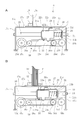
- FIG. 8A is a plan view of the measurement unit
- FIG. 8B is an elevation view of the measurement unit shown in FIG. 8A.
- the measurement unit includes a base 40a, a pair of support members 40b fixed on the base 40a with a space therebetween, and a support member extending between these support members 40b. And a horizontal linear guide rail 40c supported by the member 40b.
- the measurement unit also includes a sliding body 40d that is slidably attached to the guide rail 40c.
- the sliding body 40d has a flat measurement surface 40e extending perpendicularly to the guide rail 40c.
- the measurement unit also includes a fixed body 40f fixed on the base 40a. The sliding body 40d slides in a direction approaching and separating from the fixed body 40f, and the fixed body 40f has a flat reference surface 40g that faces the measurement surface 40e of the sliding body 40d and can be brought into contact with the measurement surface 40e. is doing.
- the measuring unit further includes a moving distance measuring means for measuring the moving distance of the measuring surface 40e relative to the reference surface 40g with the position where the measuring surface 40e of the sliding body 40d is in contact with the reference surface 40g of the fixed body 40f as a zero point. is doing.
- the moving distance measuring means includes a pair of pulleys 40h and 40i disposed on both ends of the guide rail 40c and attached on the base 40a, and an endless belt 40j stretched between the pulleys 40h and 40i. Yes.
- a sliding body 40d is connected to the endless belt 40j.
- the moving distance measuring unit further includes a rotary encoder 40k connected to the rotating shaft of one pulley 40h.
- the measurement unit is arranged adjacent to a table for aligning the body P, which is provided adjacent to the body insertion position A of the bookbinding apparatus.
- the measuring unit has an auxiliary table portion 40m connected to the table so as to be at the same level.
- the auxiliary table portion 40m is provided with a slot (not shown) extending along the guide rail 40c.
- the base 40a is fixed to the lower surface of the auxiliary table portion 40m, and at least the reference surface 40g of the fixed body 40f and the sliding body 40d.
- the measurement surface 40e protrudes from the upper surface of the auxiliary table portion 40m through the slot, and the measurement surface 40e is slidably disposed.
- the body P is aligned on the table by the operator's hand and then inserted between the reference surface 40g and the measurement surface 40e of the measurement unit.
- the body P is supported in an upright state by one hand of the operator, the sliding body 40d is slid by the other hand of the operator, and the body P is fixed to the fixed body 40f by the measurement surface 40e of the sliding body 40d.
- the thickness of the body P is measured by being sandwiched between the reference surface 40g and the measurement surface 40e while being pressed against the reference surface 40g.
- an object of the present invention is to make it possible to measure the thickness of the main body easily and in a short time and with high accuracy in the perfect binding apparatus.
- a conveyance path a series of processing units that are arranged along the conveyance path and that performs a perfect binding process, and at least one that can move along the conveyance path
- Two clamp units and a first driving mechanism for moving the clamp unit, and the body is sandwiched between a pair of clamp plates of the clamp unit and wirelessly passed through the series of processing units sequentially.
- Binding binding processing is performed, and two or more processing units engage or contact with both sides of the back of the main body protruding from between the pair of clamp plates, and the pair of members.
- a distance adjusting means for moving in a direction toward or away from each other, and further, a first control for controlling the clamp unit and the distance adjusting means A knit and a measurement unit for measuring the thickness of the main body, and before starting the bookbinding process, the thickness of the main body is measured by the measurement unit, and the pair of clamps is based on the obtained measurement values.
- the measurement unit includes: A base having an upper surface on which the main body is placed; and a fixed body attached to the upper surface of the base; the fixed body has a reference surface perpendicular to the upper surface; And a guide rail attached to the base and extending perpendicularly to the reference plane, and attached to the guide rail and slidable in a direction toward or away from the fixed body.
- a movable body and a second drive mechanism that slides the movable body the movable body having two wall surfaces that are spaced apart from each other in the axial direction of the guide rail, A space is formed between the two wall surfaces, and the measurement unit is further disposed in the space of the movable body, attached to the guide rail, and slid between the two wall surfaces.
- the measurement body has a measurement surface facing a reference surface of the fixed body, and the measurement unit is further disposed between the movable body and the measurement body.
- An elastic biasing means for constantly pressing the measuring body against a wall surface closer to the fixed body of the two wall surfaces, and the base or the fixed body, wherein the body is a reference surface of the fixed body.
- the body stops and Measurement by the moving distance measuring means made when, thereby, perfect binding and wherein the thickness of the main body is measured is provided.
- the elastic biasing means of the measuring unit comprises a coil spring.
- the first sensor comprises a photoelectric sensor and the second sensor comprises a proximity sensor.
- the base has an upper wall forming the upper surface and an internal space formed below the upper wall, and the guide is in the internal space.
- a rail is attached, and the movable body includes first and second side walls that form the two wall surfaces, respectively, and a connection wall that connects upper ends of the first and second side walls, An opening for inserting the guide rail is formed in each of the first and second side walls, a through hole for inserting the guide rail is formed in the measuring body, and the movable body is the base.
- the measuring body is disposed in the space of the movable body, and the movable body and the measuring body are fitted into the guide rail through the opening and the through hole, respectively.
- the coil spring is fitted in a compressed state between a wall surface of the movable body far from the fixed body and the measurement body, and the connection wall of the movable body and the upper wall of the base are aligned with each other.
- first and second guide holes extending in parallel to the guide rail are formed, and the measuring body includes an extension portion that protrudes upward from the upper surface of the base through the first and second guide holes. And the measurement surface is provided on the extended portion.
- the base has an upper wall forming the upper surface and an internal space formed below the upper wall, and the guide is in the internal space.
- a rail is attached, and the movable body includes first and second side walls that form the two wall surfaces, respectively, and a connection wall that connects upper ends of the first and second side walls, An opening for inserting the guide rail is formed in each of the first and second side walls, and a first through hole for inserting the guide rail is formed in the measurement body.
- a rod parallel to the guide rail extending between the first and second side walls on each side of the measurement body is attached in the space. The rod is inserted into the measurement body for insertion of the rod.
- the measuring body is arranged in the internal space of the base, the measuring body is arranged in the space of the movable body, and the movable body and the measuring body are respectively connected to the guide rail through the opening and the first through hole. And the measurement body is fitted into the rod through the second through hole, and the coil spring is fitted in a compressed state between the measurement body and the wall surface of the rod far from the fixed body.
- the connecting wall of the movable body and the upper wall of the base are formed with first and second guide holes that are aligned with each other and extend in parallel with the guide rail. An extension portion that protrudes upward from the upper surface of the base through the second guide hole is provided, and the measurement surface is provided in the extension portion.
- the second drive mechanism includes a pair of first pulleys arranged in the inner space of the base with an interval in the axial direction of the guide rail.
- Each of the pair of first pulleys has a rotation axis perpendicular to the axis of the guide rail, and the second drive mechanism is further stretched between the pair of first pulleys,
- a first timing belt having the movable body coupled to a part thereof; and a motor disposed in an internal space of the base and coupled to a rotation shaft of one of the first pulleys.
- the moving distance measuring means includes a pair of second pulleys arranged in the internal space of the base with an interval in the axial direction of the guide rail.
- Each of the pair of second pulleys has a rotation axis perpendicular to the axis of the guide rail, and the moving distance measuring means is further stretched between the pair of second pulleys,
- the second endless belt, to which the measurement body is connected in part, is connected to the rotation shaft of one of the second pulleys, and the rotation amount of the second pulley is set to the movement distance of the measurement surface of the measurement body.
- Means for converting and outputting the travel distance on both sides of the second guide hole on the upper surface of the base, a slip promotion plate extending in parallel with the second guide hole is attached. .
- the movable body slides in a direction approaching the fixed body only when a detection signal is continuously output from the first sensor for a predetermined time.
- the measurement by the moving distance measuring means is performed when a detection signal is output from the second sensor. However, if no detection signal is output from the first sensor, measurement by the moving distance measuring means is not performed, and the movable body slides to the original position in a direction away from the fixed body.
- the measurement by the moving distance measuring means is performed when a predetermined time elapses after the detection signal is output from the second sensor and the movable body stops. Made.
- the first control unit determines the next body thickness.
- the measured value is recorded in a memory, and when the leading body sandwiched between the pair of clamp plates reaches a predetermined position on the conveying path, the leading body is located upstream from the position of the leading body.
- An interval between the pair of members of the processing unit is adjusted based on the measurement value recorded in the memory, and thereafter, an interval between the pair of members of the processing unit on the downstream side of the predetermined position,
- an adjustment is made based on the measurement value recorded in the memory, and after the completion of the previous body's perfect binding process, the distance between the pair of clamp plates is adjusted. , Serial adjusted based on the measured values recorded in the memory.
- the series of processing units includes at least a milling unit, a gluing unit, and a cover unit, and the milling unit serves as the pair of members as the back of the body.
- the milling unit serves as the pair of members as the back of the body.
- a pair of guide plates that support both sides of the back of the body protruding from the pair of clamp plates during the cutting process, and the cover attaching unit attaches a cover to the back of the body as the pair of members. It has a pair of nip plates that press the cover against both sides of the back of the body when wearing.
- the operator moves the movable body automatically by simply placing the aligned body in front of the reference surface of the fixed body and supporting it in an upright state by hand.
- productivity can be improved significantly conventionally.
- the body is always pressed against the reference surface of the stationary body with a constant pressure by the measurement surface of the movable body, so that even when the body is thick, the air is sufficiently ventilated, thereby improving the measurement accuracy. , Bookbinding finish is improved.
- FIG. 1 is a plan view schematically showing a configuration of a perfect binding apparatus according to an embodiment of the present invention.
- FIG. FIG. 2 is a side view of the perfect binding device shown in FIG. 1. It is a figure which shows the measurement unit of the perfect binding apparatus shown by FIG. 1, (A) is a perspective view, (B) is a perspective view similar to (A) of the state from which the base was removed. is there.
- FIG. 4 is a schematic side view illustrating a measurement operation of the measurement unit illustrated in FIG. 3.
- FIG. 4 is a schematic side view illustrating a measurement operation of the measurement unit illustrated in FIG. 3.
- FIG. 7 It is a figure which shows the measurement unit by another Example of this invention, (A) is the perspective view which looked at the measurement unit in the state from which the base was removed, and (B) is the base removed. It is the perspective view which looked at the measurement unit of the state which was read from the lower part, and (C) is a perspective view of the measurement object of a measurement unit. It is a perspective view which shows schematically the structure of the conventional perfect binding apparatus. It is a figure which shows the measurement unit with which the bookbinding apparatus of FIG. 7 was equipped, (A) is a top view, (B) is an elevation view.
- FIG. 1 is a plan view schematically showing a configuration of a perfect binding apparatus according to an embodiment of the present invention
- FIG. 2 is a side view of the perfect binding apparatus shown in FIG.
- the saddle stitching apparatus of the present invention includes a conveyance path F and a series of processing units (a milling unit B and a gluing unit C) that are arranged along the conveyance path F and perform a perfect binding process.
- a cover attaching unit D) a single clamp unit 1 that can reciprocate along the conveyance path F, and a first drive mechanism that reciprocates the clamp unit 1.
- A represents a body insertion position where a body (not shown) is inserted and sandwiched between a pair of clamp plates 1a and 1b of the clamp unit 1, and the body insertion position A includes An alignment plate 1c that supports the back of the body when the body is sandwiched between the pair of clamp plates 1a and 1b is provided.
- E denotes a cover supply unit that supplies a cover Q to the cover attaching unit D.
- the first drive mechanism includes a guide rail 10 that is disposed above the processing units B to D with a space therebetween and extends along the transport path F.
- the guide rail 10 includes an endless chain that is provided alongside the guide rail 10 and reciprocates.
- the clamp unit 1 is attached to the guide rail 10 so as to be slidable, and is connected to a part of the endless chain, and reciprocates along the transport path F along with the reciprocating revolving motion of the endless chain.
- the guide rail 10 is attached so that one end 10a on the cover attaching unit D side can turn around a turning shaft 11 fixed to the frame 12 of the bookbinding apparatus.
- a motor 13 is disposed on the other end 10 b side of the guide rail 10 and is fixed to the frame 12.
- a rotating plate 14 is attached to the rotating shaft of the motor 13, and one end of a rod 15 is pivotally attached to the outer periphery of the rotating plate 14 by a pin 16a.
- the other end of the rod 15 is attached to the guide rail 10 by a pin 16b.
- the other end 10b is pivotably attached.
- the guide rail 10 when the rod 15 moves up and down by the rotational drive of the motor 13, the guide rail 10 has a first position where the guide rail 10 extends horizontally along the conveyance path F around the turning shaft 11, and the guide rail. 10 takes a second position where it tilts around the turning shaft 11 as a fulcrum and retracts upward from each of the processing units B to D.
- the pair of clamp plates 1a and 1b of the clamp unit 1 includes a fixed clamp plate 1a and a movable clamp plate 1b.
- the movable clamp plate 1b is movable in the direction of approaching and separating from the fixed clamp plate 1a by driving of a motor M1 provided in the clamp unit 1.
- a guide rail is arrange
- the body is arranged such that both sides of the back protrude from the pair of clamp plates 1a and 1b below the pair of clamp plates 1a and 1b. Then, the bookbinding process is performed while the body is conveyed by the clamp unit 1 and sequentially passed through the series of processing units B to D.
- the guide rail 10 turns from the first position to the second position, and the clamp unit 1 is returned to the body insertion position A along the guide rail 10 in the opposite direction to the front.
- the body with the cover Q attached is discharged from the pair of clamp plates 1a and 1b.
- the milling unit B includes a milling cutter 2a and a pair of parallel guide plates 2b and 2c.
- the pair of guide plates 2b and 2c includes a fixed guide plate 2b and a movable guide plate 2c.
- the movable guide plate 2c is moved toward or away from the fixed guide plate 2b by driving a motor M2 provided in the milling unit B, whereby the distance between the pair of guide plates 2b and 2c can be adjusted. .
- the pair of guide plates 2b and 2c waits in a state in which the distance between them is adjusted in advance according to the thickness of the body.
- both sides of the back of the body protruding from the pair of clamp plates 1a and 1b are the pair of guide plates 2b. 2c.
- the back of the main body is cut, and a pretreatment is performed to uniformly adhere the glue to the entire back of the main body.
- the body sandwiched between the pair of clamp plates 1a and 1b is sent to the gluing unit C.
- the gluing unit C wipes off the extra glue from the glue tank 3a for containing glue, a glue roller 3b to glue the back of the body, a pair of horizontal glue rollers 3c and 3d to glue both sides of the back of the body. And a roller 3e.
- the pair of horizontal glue rollers 3c and 3d includes a fixed horizontal glue roller 3c and a movable horizontal glue roller 3d, and the movable horizontal glue roller 3d is moved toward and away from the fixed horizontal glue roller 3c by driving of the motor M3. It is possible to move in the direction.
- the pair of horizontal glue rollers 3c and 3d waits in a state in which the distance between them is adjusted in advance according to the thickness of the body. In this way, while the body sandwiched between the pair of clamp plates 1a and 1b passes over the glue tank 3a, the pair of horizontal glue rollers 3c and 3d are engaged with both sides of the back of the body, and both sides of the back of the body are engaged. Gluing is done. When gluing is completed, the body sandwiched between the pair of clamp plates 1a and 1b is sent to the cover attaching unit D.
- the cover attaching unit D includes a bottom plate 4c and a pair of nip plates 4a and 4b.
- the pair of nip plates 4a and 4b includes a fixed nip plate 4b and a movable nip plate 4a.
- the distance between the pair of nip plates 4a and 4b can be adjusted by moving the movable nip plate 4a toward and away from the fixed nip plate 4 by driving a motor M4 provided in the cover attaching unit D. .
- the pair of nip plates 4a and 4b waits in a state in which the distance between them is adjusted in advance according to the thickness of the body.
- the cover sheet supply unit E includes a tray on which the cover sheet Q is placed, and a cover sheet transport mechanism that transports the cover sheet Q from the tray onto the bottom plate 4c and the pair of nip plates 4a and 4b of the cover sheet attaching unit D.
- the cover sheet transport mechanism has a pair of crease forming rollers 5a and 5b that crease a predetermined position of the cover sheet Q.
- the pair of fold forming rollers 5a and 5b includes a fixed fold forming roller 5a and a movable fold forming roller 5b.
- the movable fold forming roller 5b is moved in the direction of approaching and separating from the fixed fold forming roller 5a by the driving of the motor M5, so that the pair of fold forming rollers 5a and 5b has a distance between them. It waits in the state adjusted beforehand according to thickness.
- the cover sheet Q is conveyed from the cover sheet supply unit E onto the bottom plate 4c and the pair of nip plates 4a and 4b of the cover attachment unit D by the conveyance mechanism. During this conveyance, two parallel folds are formed at predetermined positions on the cover Q by the pair of fold forming rollers 5a and 5b.
- the body sandwiched between the pair of clamp plates 1a and 1b stops at a position where the back of the body faces the back part of the cover Q (the part between the parallel folds of the cover Q).
- the bottom plate 4c and the pair of nip plates 4a and 4b are lifted, and the cover sheet Q is pressed against the back of the body by the rising bottom plate 4c, and at the same time, the movable nip plate 4a is moved in the direction approaching the fixed nip plate 4b.
- the cover Q is pressed against both sides of the back of the main body, the cover Q is stuck to the main body P, and the bookbinding product is completed.
- the transport path is formed in a straight line, and a single clamp unit reciprocates on the transport path.
- the transport path is formed in a loop shape, and a plurality of clamps are provided. The unit circulates in one direction on the transport path with a certain interval, and during that time, a bookbinding process is performed by a series of processing units.
- a measuring unit 6 for measuring the thickness of the body is also provided.
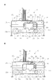
- 3A and 3B are diagrams showing the measurement unit, in which FIG. 3A is a perspective view, and FIG. 3B is a view similar to FIG. 3A with the base removed.
- 4 and 5 are schematic side views for explaining the measurement operation of the measurement unit shown in FIG. 3 to 5, the measurement unit 6 includes a base 17 having an upper surface 17d on which the body P is placed.
- the base 17 has an upper wall 17a that forms an upper surface 17d, side walls 17b and 17c that are connected to both side edges of the upper wall 17a and function as legs, and are located below the upper wall 17a.
- An internal space 18 is formed.
- a fixed body 19 is attached to the upper surface 17 d of the base 17.
- the fixed body 19 has a reference surface 19a perpendicular to the upper surface 17d.
- the fixed body 19 is composed of a plate-like member substantially bent in an L shape, and one folded piece portion is attached to the upper surface 17d, while the other folded piece portion is perpendicular to the upper surface 17d.
- the reference surface 19a is formed upright.
- a guide rail 20 is attached in the internal space 18 of the base 17 and extends perpendicularly to the reference surface 19a.
- the measurement unit 6 also includes a movable body 21 that is attached to the guide rail 20 and is slidable in a direction approaching or separating from the fixed body 19.
- the movable body 21 includes a first side wall 21a and a second side wall 21b that are positioned at an interval in the axial direction of the guide rail 20, and a connection wall 21c that connects the upper ends of the first and second side walls 21a and 21b.
- a space 21d is formed between the first and second side walls 21a and 21b.
- the measurement body 22 is arrange
- openings for insertion of the guide rail 20 are respectively formed in the first and second side walls 21a, 21b of the movable body 21, and a through hole for insertion of the guide rail 20 is formed in the measurement body 22.
- the movable body 21 is disposed in the internal space 18 of the base 17, the measurement body 22 is disposed in the space 21d of the movable body 21, and the movable body 21 and the measurement body 22 are guided through the opening and the through hole, respectively.
- the rail 20 is fitted.
- a coil spring 24 is fitted in a compressed state between the measurement body 22 and the wall surface 21f (the wall surface far from the fixed body 19) of the second side wall 21b of the movable body 21 in the guide rail 20, thereby The measuring body 22 is always pressed against the wall surface 21e of the first side wall 21a of the movable body 21 (the wall surface closer to the fixed body 19).
- a known appropriate elastic urging means according to Hook's law can be used.
- connection wall 21c of the movable body 21 and the upper wall 17a of the base 17 are formed with first and second guide holes 21g and 17e that are aligned with each other and extend parallel to the guide rail 20.
- one end of the first guide hole 21 g of the movable body 21 is in a position that does not prevent the measurement body 22 from coming into contact with the wall surface 21 e of the first side wall 21 a of the movable body 21.
- One end of the guide hole 17 e is in a position that does not prevent the measurement surface 22 b of the measurement body 22 from coming into contact with the reference surface 19 a of the fixed body 19.
- the measuring body 22 has an extended portion 22a that protrudes upward from the upper surface 17d of the base 17 through the first and second guide holes 21g and 17e.
- the extended portion 22A includes a reference for the fixed body 19.
- a measurement surface 22b facing the surface 19a is formed.
- the measurement unit 6 also includes a second drive mechanism that slides the movable body 21.
- the second drive mechanism includes a pair of first pulleys 25a and 25b disposed in the internal space 18 of the base 17 with an interval in the axial direction of the guide rail 20.
- Each of the pair of first pulleys 25 a and 25 b has a rotation axis perpendicular to the axis of the guide rail 20.
- the second drive mechanism is further stretched between a pair of first pulleys 25a and 25b, a first timing belt 25c having a movable body 21 connected to a part of the first drive belt 25a, and an internal space 18 of the base 17.
- a motor 25d connected to the rotating shaft of one first pulley 25a.
- the first pulley 25a is rotationally driven by the motor 25d, whereby the movable body 21 is slid.
- the measurement unit 6 includes a movement distance measuring unit that measures the movement distance of the measurement surface 22b relative to the reference surface 19a with the position where the measurement surface 22b of the measurement body 22 contacts the reference surface 19a of the fixed body 19 as a zero point.
- the moving distance measuring means includes a pair of second pulleys 26 a and 26 b that are arranged in the internal space 18 of the base 17 with an interval in the axial direction of the guide rail 20.
- Each of the pair of second pulleys 26 a and 26 b has a rotation axis perpendicular to the axis of the guide rail 20.
- the moving distance measuring means is further stretched between a pair of second pulleys 26a and 26b, and a second timing belt 26c having a measuring body 22 connected to a part thereof, and one of the second pulleys 26b.
- a means for converting the amount of rotation of the second pulley 26b into the moving distance of the measuring surface 22b of the measuring body 22 and outputting the moving distance, for example, a rotary encoder 26d, is connected to the rotating shaft.
- the second drive mechanism and the moving distance measuring means are controlled by the second control unit 7b.
- the measurement unit 6 further includes a first sensor 27 that is provided on the base 17 or the fixed body 19 and detects when the body P is placed in front of the reference surface 19 a of the fixed body 19.
- the first sensor 27 is composed of a photoelectric sensor, and is attached to one folded piece portion of the fixed body 19 so as to face the other folded piece portion where the detection unit stands. Further, a detection window 19b is formed at a position corresponding to the detection portion of the first sensor 27 in the other folded piece portion.
- the measurement unit 6 is disposed on the movable body 21 and / or the measurement body 22, and the measurement body 22 resists the elastic force of the coil spring 24 and the wall surface 21 e (on the fixed body) of the first side wall 21 a of the movable body 21.
- a second sensor 28 is provided for detecting when a predetermined distance from the nearest wall surface.
- the second sensor 28 is a proximity sensor, and is attached to the upper surface of the connection wall 21c of the movable body 21 so that the detection unit faces upward.
- a metal plate 29 that is paired with the second sensor 28 is attached to the upper surface of the measurement body 22. The metal plate 29 is close to the detection unit of the second sensor 28 and is detected by the second sensor 28 when the measurement body 22 is separated from the wall surface 21e of the movable body 21 by a predetermined distance.
- slip promotion plates 30a and 30b extending in parallel with the second guide hole 17e are attached.
- the measurement by the measurement unit 6 is performed as follows. Prior to the start of measurement, the movable body 21, and thus the measurement surface 22b of the measurement body 22, is at an initial position away from the reference surface 19a of the fixed body 19 (see FIG. 4A). Then, after the body P is aligned by an operator on an appropriate plane provided in the bookbinding apparatus, the body P is placed in front of the reference surface 19a so as to block the detection unit of the first sensor 27, It is supported in a standing state by the hand of a person. At that time, the body P is detected by the first sensor 27, and the first sensor 27 outputs a detection signal. The second control unit 7b receives this detection signal and operates the second drive mechanism, whereby the movable body 21 starts a sliding motion toward the fixed body 19.
- the first sensor 27 is movable only when a detection signal is continuously output for a predetermined time. It is preferable that the body 21 starts to slide.
- the body P is pushed by the measurement surface 22b of the measurement body 22 toward the reference surface 19a until it is sandwiched between the reference surface 19a and the measurement surface 22b (FIG. 4B). reference). At this time, even the thick body P is pushed and moved smoothly by the action of the slip promotion plates 30a and 30b.
- the measurement body 22 cannot move further toward the fixed body 19 by the measurement surface 22b coming into contact with the body P.
- the movable body 21 continues the sliding motion after that. Thereby, the measuring body 22 is gradually separated from the wall surface 21e of the first side wall 21a of the movable body 21 while the coil spring 24 is gradually compressed (see FIG. 5A).
- the metal plate 28 of the measurement body 22 is detected by the detection unit of the second sensor 28 of the movable body 21, and a detection signal is output from the second sensor 28. Is output.
- the second control unit 7b receives this detection signal, stops the second drive mechanism, and thereby stops the movable body 21.
- the second control unit 7b activates the moving distance measuring means, whereby the thickness of the body P is measured (see FIG. 5B).
- the measured value data is sent to the second control unit 7b.
- the body P is always pressed against the reference surface 19a of the fixed body 19 with a constant pressure by the measurement surface 22b of the measurement body 22.
- the magnitude of the pressure exerted on the body P at the time of measurement can be adjusted.
- the detection signal when the detection signal is output from the second sensor 28, if the detection signal is output from the first sensor 27, the measurement by the moving distance measuring means is performed. However, if the detection signal is not output from the first sensor 27, the measurement by the moving distance measuring means is not performed, and the movable body 21 slides to the initial position in the direction away from the fixed body 19.
- the measurement by the moving distance measuring means is preferably performed when a predetermined time has elapsed after the detection signal is output from the second sensor 27 and the movable body 21 is stopped. Thereby, even if the main body P is thick, the air is sufficiently removed, and the measurement accuracy is improved.
- the movable body 21 is automatically moved by the operator simply placing the aligned body P in front of the reference surface 19a of the fixed body 19 and supporting it in an upright state by hand. Since the thickness of the body P is measured, the measurement can be performed in a short time, and the body P can be supported using both hands at the time of measurement. Therefore, there is no risk of breaking the main body P, thereby avoiding re-measurement and reducing the burden on the operator. In particular, in the case of multi-product small-lot production, the productivity is greatly improved as compared with the conventional case.
- the body P is always pressed against the reference surface 19a of the fixed body 19 by the measurement surface 22b of the measurement body 22 at the time of measurement, even if the body P is thick, the air is sufficiently vented. As a result, the measurement accuracy is improved and the finished product is improved.
- the motor M1 of the clamp unit 1, the motor M2 of the milling unit B, the motor M3 of the gluing unit C, the motor M4 of the cover attaching unit D, and the motor M5 of the cover supplying unit E are further controlled.
- a control unit 7a, a memory 8 and a display 9 are provided. Then, data transmission is performed between the first and second control units 7a and 7b.
- the data of the measurement value is sent from the second control unit 7b to the first control unit 7a and is displayed on the display 9. Is displayed. Further, based on the measured values obtained, the distance between the pair of clamp plates 1a and 1b before the body P is clamped, the distance between the pair of guide plates 2b and 2c of the milling unit B, and the pair of horizontal glue rollers 3c of the gluing unit C.
- the distance between the pair of nip plates 4a and 4b of the cover attaching unit D, and the distance between the pair of fold forming rollers 5a and 5b of the cover supply unit E correspond to the thickness of the body P by the control unit 7. To be adjusted in advance.
- the first control unit 7a stores the measured value of the thickness of the next body P in the memory. Record in 8.
- the processing units B to E located upstream from the previous body P position. The distance between the pair of members 2b, 2c; 3c, 3d; 4a, 4b; 5a, 5b is adjusted based on the measured value recorded in the memory 8.
- the distance between the pair of members 2b, 2c; 3c, 3d; 4a, 4b; 5a, 5b of the processing units B to E downstream of the predetermined position is determined so that the previous body has the processing units B to E. Is adjusted based on the measurement value recorded in the memory 8, and after the bookbinding process of the main body P is completed, the interval between the pair of clamp plates 1 a and 1 b is recorded in the memory 8. Adjust based on.
- a rotary encoder is attached to one of a pair of sprockets that turn the endless chain constituting the first drive mechanism. Then, after the clamp unit 1 clamps the body P at the body insertion position A, a conveyance start signal is output from the sensor disposed at the clamp unit 1 or the body insertion position when leaving the body insertion position. And the control part 7 measures the conveyance distance of the main body P by starting the count of the pulse number output from a rotary encoder simultaneously with receiving this conveyance start signal. Then, when the predetermined conveyance distance is reached, it is detected that the body P has reached the predetermined position. In this embodiment, when the body P reaches the cover attachment unit D, it is assumed that the position reached in advance is reached.
- FIG. 6 is a view showing a measurement unit according to another embodiment of the present invention
- (A) is a perspective view of the measurement unit in a state where the base is removed
- (B) is a view from above. It is the perspective view which looked at the measurement unit in the state where the base was removed from the lower part
- (C) is a perspective view of the measurement object of a measurement unit.
- the embodiment shown in FIG. 6 differs from the embodiment shown in FIGS. 1 to 5 only in the configuration of the movable body and the measurement body of the measurement unit. Therefore, in the following, the same components as those shown in FIGS. 1 to 5 are denoted by the same reference numerals, and detailed description thereof is omitted.
- the movable body 31 has a hollow rectangular parallelepiped shape without a bottom, and includes an upper wall 31c, first and second side walls 31a and 31b facing each other, and Opposite third and fourth side walls 31d and 31e are provided. And the opening for insertion of the guide rail 20 is formed in the 1st and 2nd side walls 31a and 31b, respectively.
- the measuring body 32 has a rectangular extension plate 33 smaller than the first side wall 31a on the end surface facing the first side wall 31a of the movable body 31.
- a first through hole 32 c for inserting the guide rail 20 is formed in the measurement body 32.
- rods 34 that are parallel to the guide rail 20 and extend between the first and second side walls 31a and 31b on both sides of the measurement body 32 are attached.
- second through holes 33a and 33b for inserting the rod 34 are formed on both sides of the expansion plate 33 of the measurement body 32.
- the movable body 31 is arrange
- the measurement body 32 is arrange
- the measuring body 32 is fitted into the rod 34 through the second through holes 33a and 33b.
- a coil spring 35 is fitted in a compressed state between the wall surface of the second side wall 31 b of the movable body 31 (the wall surface far from the fixed body 19) and the expansion plate 33 of the measurement body 32 in the rod 34.
- the measurement body 32 expansion plate 33
- the measurement body 32 is constantly pressed against the wall surface of the first side wall 31a of the movable body 31 (the wall surface closer to the fixed body 19) by the elastic biasing force of the coil spring 35.
- First and second guide holes 31f and 17e that are aligned with each other and extend parallel to the guide rail 20 are formed in the upper wall 31c of the movable body 31 and the upper wall 17a of the base 17.
- the measurement body 32 has an extended portion 32a that protrudes upward from the upper surface 17d of the base 17 through the first and second guide holes 31f and 17e, and a measurement surface 32b is provided on the extended portion 32a.
- a second sensor (proximity sensor) 28 is attached to the third side wall 31d of the movable body 31 with the detection portion facing outward, and a slot 31g parallel to the guide rail 20 is formed on the third side wall 31d. It is formed.
- a metal plate 29 is attached to the upper surface of the measurement body 32 and protrudes to the outside through the slot 31g. As the measuring body 32 moves with respect to the movable body 31, the metal plate 29 moves along the slot 31g, and the measuring body 32 (expansion plate 33) moves from the wall surface of the first side wall 31a of the movable body 31 to a predetermined amount. When the distance is long, the metal plate 29 approaches the detection unit of the second sensor 28 and is detected by the second sensor 28.
- the movable body and the measuring body are remarkably compact, and the constant length of the coil spring can be secured, so that the pressure can be easily adjusted during the thickness measurement.
Landscapes
- Engineering & Computer Science (AREA)
- Mechanical Engineering (AREA)
- Folding Of Thin Sheet-Like Materials, Special Discharging Devices, And Others (AREA)
- A Measuring Device Byusing Mechanical Method (AREA)
Abstract
Priority Applications (6)
| Application Number | Priority Date | Filing Date | Title |
|---|---|---|---|
| JP2013516093A JP5713510B2 (ja) | 2011-05-23 | 2011-05-23 | 無線綴じ製本装置 |
| DK11866193.3T DK2666644T3 (en) | 2011-05-23 | 2011-05-23 | Binding machine |
| US13/978,614 US8950994B2 (en) | 2011-05-23 | 2011-05-23 | Perfect binding machine |
| EP11866193.3A EP2666644B1 (fr) | 2011-05-23 | 2011-05-23 | Machine de reliure |
| PCT/JP2011/061729 WO2012160633A1 (fr) | 2011-05-23 | 2011-05-23 | Dispositif de reliure sans fil |
| CN201180049126.2A CN103153639B (zh) | 2011-05-23 | 2011-05-23 | 无线订合装订装置 |
Applications Claiming Priority (1)
| Application Number | Priority Date | Filing Date | Title |
|---|---|---|---|
| PCT/JP2011/061729 WO2012160633A1 (fr) | 2011-05-23 | 2011-05-23 | Dispositif de reliure sans fil |
Publications (1)
| Publication Number | Publication Date |
|---|---|
| WO2012160633A1 true WO2012160633A1 (fr) | 2012-11-29 |
Family
ID=47216737
Family Applications (1)
| Application Number | Title | Priority Date | Filing Date |
|---|---|---|---|
| PCT/JP2011/061729 Ceased WO2012160633A1 (fr) | 2011-05-23 | 2011-05-23 | Dispositif de reliure sans fil |
Country Status (6)
| Country | Link |
|---|---|
| US (1) | US8950994B2 (fr) |
| EP (1) | EP2666644B1 (fr) |
| JP (1) | JP5713510B2 (fr) |
| CN (1) | CN103153639B (fr) |
| DK (1) | DK2666644T3 (fr) |
| WO (1) | WO2012160633A1 (fr) |
Cited By (1)
| Publication number | Priority date | Publication date | Assignee | Title |
|---|---|---|---|---|
| JP2018196991A (ja) * | 2017-05-24 | 2018-12-13 | ミュラー・マルティニ・ホルディング・アクチエンゲゼルシヤフト | 無線綴じ機 |
Families Citing this family (5)
| Publication number | Priority date | Publication date | Assignee | Title |
|---|---|---|---|---|
| CN105172413A (zh) * | 2015-07-13 | 2015-12-23 | 陈璟 | 一种胶订包本一体化设备 |
| US20170129269A1 (en) | 2015-11-11 | 2017-05-11 | Sasha Dobrovolsky | Automated book assembly system and method |
| CN106427267B (zh) * | 2016-11-29 | 2017-12-22 | 湖州佳宁印刷有限公司 | 装订方便的桌面胶装机 |
| CN110576692B (zh) * | 2019-09-30 | 2024-08-30 | 温州锐光机械有限公司 | 一种自动调整书夹板机构 |
| GB202210552D0 (en) * | 2022-07-19 | 2022-08-31 | Elanders Ltd | Nipping station improvement |
Citations (3)
| Publication number | Priority date | Publication date | Assignee | Title |
|---|---|---|---|---|
| JPH11334244A (ja) * | 1998-05-28 | 1999-12-07 | Hiroshi Kobayashi | 自動化された製本方法及びこれを利用した自動製本機 |
| JP2007190744A (ja) * | 2006-01-18 | 2007-08-02 | Konica Minolta Business Technologies Inc | 製本装置及び画像形成システム |
| EP2127898A2 (fr) | 2008-05-28 | 2009-12-02 | Horizon International Inc. | Appareil de reliure de livre pour une reliure parfaite de livre |
Family Cites Families (8)
| Publication number | Priority date | Publication date | Assignee | Title |
|---|---|---|---|---|
| DE3613120C2 (de) * | 1986-04-18 | 1994-07-07 | Kolbus Gmbh & Co Kg | Einrichtung an einer Buchbindemaschine zum Positionieren von Maschinengliedern über Stellantriebe für die Umstellung auf unterschiedliche Formate von Buchblocks |
| US5364215A (en) * | 1992-09-28 | 1994-11-15 | Norfin, Inc. | Method and apparatus for preparing book covers |
| CN2430282Y (zh) * | 2000-06-29 | 2001-05-16 | 浙江先锋机械厂 | 包本机上用于粘贴封面的包本机构 |
| JP4765640B2 (ja) * | 2006-01-26 | 2011-09-07 | コニカミノルタビジネステクノロジーズ株式会社 | 画像形成システム |
| JP2008307616A (ja) * | 2007-06-12 | 2008-12-25 | Canon Finetech Inc | 用紙断裁装置 |
| CN101112841A (zh) * | 2007-08-29 | 2008-01-30 | 武汉玛丽文化用品有限公司 | 本册书刊无线胶装订方法 |
| JP2010069794A (ja) * | 2008-09-19 | 2010-04-02 | Noritsu Koki Co Ltd | 製本装置 |
| CN201471876U (zh) * | 2009-07-23 | 2010-05-19 | 何立峰 | 胶装机夹面台的机械定位夹紧装置 |
-
2011
- 2011-05-23 WO PCT/JP2011/061729 patent/WO2012160633A1/fr not_active Ceased
- 2011-05-23 US US13/978,614 patent/US8950994B2/en not_active Expired - Fee Related
- 2011-05-23 JP JP2013516093A patent/JP5713510B2/ja not_active Expired - Fee Related
- 2011-05-23 CN CN201180049126.2A patent/CN103153639B/zh not_active Expired - Fee Related
- 2011-05-23 DK DK11866193.3T patent/DK2666644T3/en active
- 2011-05-23 EP EP11866193.3A patent/EP2666644B1/fr not_active Not-in-force
Patent Citations (4)
| Publication number | Priority date | Publication date | Assignee | Title |
|---|---|---|---|---|
| JPH11334244A (ja) * | 1998-05-28 | 1999-12-07 | Hiroshi Kobayashi | 自動化された製本方法及びこれを利用した自動製本機 |
| JP2007190744A (ja) * | 2006-01-18 | 2007-08-02 | Konica Minolta Business Technologies Inc | 製本装置及び画像形成システム |
| EP2127898A2 (fr) | 2008-05-28 | 2009-12-02 | Horizon International Inc. | Appareil de reliure de livre pour une reliure parfaite de livre |
| JP2009285906A (ja) * | 2008-05-28 | 2009-12-10 | Horizon International Inc | 無線綴じ製本装置 |
Non-Patent Citations (1)
| Title |
|---|
| See also references of EP2666644A4 * |
Cited By (2)
| Publication number | Priority date | Publication date | Assignee | Title |
|---|---|---|---|---|
| JP2018196991A (ja) * | 2017-05-24 | 2018-12-13 | ミュラー・マルティニ・ホルディング・アクチエンゲゼルシヤフト | 無線綴じ機 |
| JP7029349B2 (ja) | 2017-05-24 | 2022-03-03 | ミュラー・マルティニ・ホルディング・アクチエンゲゼルシヤフト | 無線綴じ機 |
Also Published As
| Publication number | Publication date |
|---|---|
| EP2666644A1 (fr) | 2013-11-27 |
| EP2666644B1 (fr) | 2015-12-30 |
| JPWO2012160633A1 (ja) | 2014-07-31 |
| US8950994B2 (en) | 2015-02-10 |
| CN103153639A (zh) | 2013-06-12 |
| JP5713510B2 (ja) | 2015-05-07 |
| DK2666644T3 (en) | 2016-03-14 |
| CN103153639B (zh) | 2015-10-14 |
| US20130294868A1 (en) | 2013-11-07 |
| EP2666644A4 (fr) | 2014-10-29 |
Similar Documents
| Publication | Publication Date | Title |
|---|---|---|
| JP5713510B2 (ja) | 無線綴じ製本装置 | |
| EP2127898B1 (fr) | Appareil de reliure de livre pour une reliure parfaite de livre | |
| US7261507B2 (en) | Book binding method and system for saddle stitched bound booklet | |
| JP5241930B2 (ja) | 本身への貼付け前の表紙に対して折り曲げ加工用の筋を入れる装置 | |
| CN216661353U (zh) | 一种运输装置 | |
| CN103387151A (zh) | 一种翻转式整理纸叠的齐纸装置 | |
| CN111266751A (zh) | 翻转接驳台及镭雕设备 | |
| CN216514752U (zh) | 自动折叠装置 | |
| JP2011098543A (ja) | 段ボールシートの折り曲げ方法及び装置 | |
| JP6156839B2 (ja) | 帯掛け包装装置 | |
| CN208197665U (zh) | 一种瓦楞纸板压线装置 | |
| CN111890487B (zh) | 健身器材座垫加工自动打钉设备 | |
| CN117626538A (zh) | 一种吊标唛头车缝设备 | |
| CN113802358A (zh) | 自动折叠装置及自动折叠方法 | |
| CN211808085U (zh) | 酒盒外包装纸板对中限位导向机构 | |
| JP5553003B2 (ja) | 用紙処理装置 | |
| JP5569356B2 (ja) | 用紙処理装置 | |
| JP4547311B2 (ja) | 段ボールシートの折り曲げ装置。 | |
| JP5569341B2 (ja) | 用紙処理装置 | |
| CN215287208U (zh) | 一种送纸装置及裱卡机 | |
| JPH0211155Y2 (fr) | ||
| JPH0219268Y2 (fr) | ||
| JPH0713961Y2 (ja) | ファイル用台紙の端面処理装置 | |
| CN208070892U (zh) | 一种送纸组件的推送装置 | |
| CN114684435A (zh) | 一种面膜折叠装置 |
Legal Events
| Date | Code | Title | Description |
|---|---|---|---|
| WWE | Wipo information: entry into national phase |
Ref document number: 201180049126.2 Country of ref document: CN |
|
| ENP | Entry into the national phase |
Ref document number: 2013516093 Country of ref document: JP Kind code of ref document: A |
|
| 121 | Ep: the epo has been informed by wipo that ep was designated in this application |
Ref document number: 11866193 Country of ref document: EP Kind code of ref document: A1 |
|
| WWE | Wipo information: entry into national phase |
Ref document number: 13978614 Country of ref document: US |
|
| WWE | Wipo information: entry into national phase |
Ref document number: 2011866193 Country of ref document: EP |
|
| NENP | Non-entry into the national phase |
Ref country code: DE |