WO2012160638A1 - 蓄電器制御回路 - Google Patents
蓄電器制御回路 Download PDFInfo
- Publication number
- WO2012160638A1 WO2012160638A1 PCT/JP2011/061767 JP2011061767W WO2012160638A1 WO 2012160638 A1 WO2012160638 A1 WO 2012160638A1 JP 2011061767 W JP2011061767 W JP 2011061767W WO 2012160638 A1 WO2012160638 A1 WO 2012160638A1
- Authority
- WO
- WIPO (PCT)
- Prior art keywords
- balancing
- control
- control circuit
- storage device
- interruption
- Prior art date
- Legal status (The legal status is an assumption and is not a legal conclusion. Google has not performed a legal analysis and makes no representation as to the accuracy of the status listed.)
- Ceased
Links
Images



Classifications
-
- B—PERFORMING OPERATIONS; TRANSPORTING
- B60—VEHICLES IN GENERAL
- B60L—PROPULSION OF ELECTRICALLY-PROPELLED VEHICLES; SUPPLYING ELECTRIC POWER FOR AUXILIARY EQUIPMENT OF ELECTRICALLY-PROPELLED VEHICLES; ELECTRODYNAMIC BRAKE SYSTEMS FOR VEHICLES IN GENERAL; MAGNETIC SUSPENSION OR LEVITATION FOR VEHICLES; MONITORING OPERATING VARIABLES OF ELECTRICALLY-PROPELLED VEHICLES; ELECTRIC SAFETY DEVICES FOR ELECTRICALLY-PROPELLED VEHICLES
- B60L58/00—Methods or circuit arrangements for monitoring or controlling batteries or fuel cells, specially adapted for electric vehicles
- B60L58/10—Methods or circuit arrangements for monitoring or controlling batteries or fuel cells, specially adapted for electric vehicles for monitoring or controlling batteries
- B60L58/18—Methods or circuit arrangements for monitoring or controlling batteries or fuel cells, specially adapted for electric vehicles for monitoring or controlling batteries of two or more battery modules
- B60L58/22—Balancing the charge of battery modules
-
- H—ELECTRICITY
- H02—GENERATION; CONVERSION OR DISTRIBUTION OF ELECTRIC POWER
- H02J—ELECTRIC POWER NETWORKS; CIRCUIT ARRANGEMENTS OR SYSTEMS FOR SUPPLYING OR DISTRIBUTING ELECTRIC POWER; SYSTEMS FOR STORING ELECTRIC ENERGY
- H02J7/00—Circuit arrangements for charging or discharging batteries or for supplying loads from batteries
- H02J7/50—Circuit arrangements for charging or discharging batteries or for supplying loads from batteries acting upon multiple batteries simultaneously or sequentially
- H02J7/52—Circuit arrangements for charging or discharging batteries or for supplying loads from batteries acting upon multiple batteries simultaneously or sequentially for charge balancing, e.g. equalisation of charge between batteries
-
- H—ELECTRICITY
- H01—ELECTRIC ELEMENTS
- H01M—PROCESSES OR MEANS, e.g. BATTERIES, FOR THE DIRECT CONVERSION OF CHEMICAL ENERGY INTO ELECTRICAL ENERGY
- H01M10/00—Secondary cells; Manufacture thereof
- H01M10/42—Methods or arrangements for servicing or maintenance of secondary cells or secondary half-cells
- H01M10/44—Methods for charging or discharging
- H01M10/441—Methods for charging or discharging for several batteries or cells simultaneously or sequentially
-
- H—ELECTRICITY
- H02—GENERATION; CONVERSION OR DISTRIBUTION OF ELECTRIC POWER
- H02J—ELECTRIC POWER NETWORKS; CIRCUIT ARRANGEMENTS OR SYSTEMS FOR SUPPLYING OR DISTRIBUTING ELECTRIC POWER; SYSTEMS FOR STORING ELECTRIC ENERGY
- H02J7/00—Circuit arrangements for charging or discharging batteries or for supplying loads from batteries
- H02J7/50—Circuit arrangements for charging or discharging batteries or for supplying loads from batteries acting upon multiple batteries simultaneously or sequentially
- H02J7/52—Circuit arrangements for charging or discharging batteries or for supplying loads from batteries acting upon multiple batteries simultaneously or sequentially for charge balancing, e.g. equalisation of charge between batteries
- H02J7/54—Passive balancing, e.g. using resistors or parallel MOSFETs
-
- B—PERFORMING OPERATIONS; TRANSPORTING
- B60—VEHICLES IN GENERAL
- B60L—PROPULSION OF ELECTRICALLY-PROPELLED VEHICLES; SUPPLYING ELECTRIC POWER FOR AUXILIARY EQUIPMENT OF ELECTRICALLY-PROPELLED VEHICLES; ELECTRODYNAMIC BRAKE SYSTEMS FOR VEHICLES IN GENERAL; MAGNETIC SUSPENSION OR LEVITATION FOR VEHICLES; MONITORING OPERATING VARIABLES OF ELECTRICALLY-PROPELLED VEHICLES; ELECTRIC SAFETY DEVICES FOR ELECTRICALLY-PROPELLED VEHICLES
- B60L2240/00—Control parameters of input or output; Target parameters
- B60L2240/40—Drive Train control parameters
- B60L2240/54—Drive Train control parameters related to batteries
- B60L2240/545—Temperature
-
- B—PERFORMING OPERATIONS; TRANSPORTING
- B60—VEHICLES IN GENERAL
- B60L—PROPULSION OF ELECTRICALLY-PROPELLED VEHICLES; SUPPLYING ELECTRIC POWER FOR AUXILIARY EQUIPMENT OF ELECTRICALLY-PROPELLED VEHICLES; ELECTRODYNAMIC BRAKE SYSTEMS FOR VEHICLES IN GENERAL; MAGNETIC SUSPENSION OR LEVITATION FOR VEHICLES; MONITORING OPERATING VARIABLES OF ELECTRICALLY-PROPELLED VEHICLES; ELECTRIC SAFETY DEVICES FOR ELECTRICALLY-PROPELLED VEHICLES
- B60L2240/00—Control parameters of input or output; Target parameters
- B60L2240/40—Drive Train control parameters
- B60L2240/54—Drive Train control parameters related to batteries
- B60L2240/547—Voltage
-
- B—PERFORMING OPERATIONS; TRANSPORTING
- B60—VEHICLES IN GENERAL
- B60L—PROPULSION OF ELECTRICALLY-PROPELLED VEHICLES; SUPPLYING ELECTRIC POWER FOR AUXILIARY EQUIPMENT OF ELECTRICALLY-PROPELLED VEHICLES; ELECTRODYNAMIC BRAKE SYSTEMS FOR VEHICLES IN GENERAL; MAGNETIC SUSPENSION OR LEVITATION FOR VEHICLES; MONITORING OPERATING VARIABLES OF ELECTRICALLY-PROPELLED VEHICLES; ELECTRIC SAFETY DEVICES FOR ELECTRICALLY-PROPELLED VEHICLES
- B60L2240/00—Control parameters of input or output; Target parameters
- B60L2240/40—Drive Train control parameters
- B60L2240/54—Drive Train control parameters related to batteries
- B60L2240/549—Current
-
- H—ELECTRICITY
- H01—ELECTRIC ELEMENTS
- H01M—PROCESSES OR MEANS, e.g. BATTERIES, FOR THE DIRECT CONVERSION OF CHEMICAL ENERGY INTO ELECTRICAL ENERGY
- H01M10/00—Secondary cells; Manufacture thereof
- H01M10/42—Methods or arrangements for servicing or maintenance of secondary cells or secondary half-cells
- H01M10/425—Structural combination with electronic components, e.g. electronic circuits integrated to the outside of the casing
- H01M2010/4271—Battery management systems including electronic circuits, e.g. control of current or voltage to keep battery in healthy state, cell balancing
-
- H—ELECTRICITY
- H02—GENERATION; CONVERSION OR DISTRIBUTION OF ELECTRIC POWER
- H02J—ELECTRIC POWER NETWORKS; CIRCUIT ARRANGEMENTS OR SYSTEMS FOR SUPPLYING OR DISTRIBUTING ELECTRIC POWER; SYSTEMS FOR STORING ELECTRIC ENERGY
- H02J2105/00—Networks for supplying or distributing electric power characterised by their spatial reach or by the load
- H02J2105/30—Networks for supplying or distributing electric power characterised by their spatial reach or by the load the load networks being external to vehicles, i.e. exchanging power with vehicles
- H02J2105/33—Networks for supplying or distributing electric power characterised by their spatial reach or by the load the load networks being external to vehicles, i.e. exchanging power with vehicles exchanging power with road vehicles
- H02J2105/37—Networks for supplying or distributing electric power characterised by their spatial reach or by the load the load networks being external to vehicles, i.e. exchanging power with vehicles exchanging power with road vehicles exchanging power with electric vehicles [EV] or with hybrid electric vehicles [HEV]
-
- Y—GENERAL TAGGING OF NEW TECHNOLOGICAL DEVELOPMENTS; GENERAL TAGGING OF CROSS-SECTIONAL TECHNOLOGIES SPANNING OVER SEVERAL SECTIONS OF THE IPC; TECHNICAL SUBJECTS COVERED BY FORMER USPC CROSS-REFERENCE ART COLLECTIONS [XRACs] AND DIGESTS
- Y02—TECHNOLOGIES OR APPLICATIONS FOR MITIGATION OR ADAPTATION AGAINST CLIMATE CHANGE
- Y02E—REDUCTION OF GREENHOUSE GAS [GHG] EMISSIONS, RELATED TO ENERGY GENERATION, TRANSMISSION OR DISTRIBUTION
- Y02E60/00—Enabling technologies; Technologies with a potential or indirect contribution to GHG emissions mitigation
- Y02E60/10—Energy storage using batteries
-
- Y—GENERAL TAGGING OF NEW TECHNOLOGICAL DEVELOPMENTS; GENERAL TAGGING OF CROSS-SECTIONAL TECHNOLOGIES SPANNING OVER SEVERAL SECTIONS OF THE IPC; TECHNICAL SUBJECTS COVERED BY FORMER USPC CROSS-REFERENCE ART COLLECTIONS [XRACs] AND DIGESTS
- Y02—TECHNOLOGIES OR APPLICATIONS FOR MITIGATION OR ADAPTATION AGAINST CLIMATE CHANGE
- Y02T—CLIMATE CHANGE MITIGATION TECHNOLOGIES RELATED TO TRANSPORTATION
- Y02T10/00—Road transport of goods or passengers
- Y02T10/60—Other road transportation technologies with climate change mitigation effect
- Y02T10/70—Energy storage systems for electromobility, e.g. batteries
Definitions
- the present invention relates to a battery control circuit mounted on a power supply device using power storage means such as a lithium secondary battery, a nickel metal hydride battery, a lead battery, or an electric double layer capacitor.
- power storage means such as a lithium secondary battery, a nickel metal hydride battery, a lead battery, or an electric double layer capacitor.
- a power storage device mounted on an electric vehicle (EV), a plug-in hybrid vehicle (PHEV), or a hybrid vehicle (HEV) it is common to configure a power storage unit by connecting a plurality of capacitors in series.
- EV electric vehicle
- PHEV plug-in hybrid vehicle
- HEV hybrid vehicle
- SOC state of Charge
- the SOC usage range is assumed to be wide, such as PHEV or EV
- the deterioration of the battery is likely to proceed in a situation where the SOC is high or low, so the SOC is lowered if the SOC is too high. If the SOC is too low, it is necessary to take measures such as preventing further reduction of the SOC.
- a balancing circuit composed of a bypass resistor and a bypass switch connected in parallel to the capacitors, and the state of the capacitors
- a method has been proposed in which a capacitor control unit to be monitored is mounted, and the capacitor control unit controls the bypass switch of the balancing circuit based on the amount of voltage variation.
- this is a balancing method for forcibly discharging a capacitor having a high voltage to equalize the voltage.
- the average value of the charge capacities of all the cells of the assembled battery is obtained only when the slope
- the previous balancing interruption information (old state information) stored in the storage device and the capacitor information (new state information) acquired at the time of starting this time are stored.
- the capacitor information (new state information) acquired at the time of starting this time are stored.
- the storage battery control circuit of the present invention has a storage device, and includes control means for monitoring and balancing control of a plurality of capacitors connected in series, and the control means calculates based on the states of the plurality of storage batteries.
- the information for balancing control is stored in the storage device, and balancing control is performed based on the information stored in the storage device.
- the control means stores the information at the time of the interruption regarding the balancing in the storage device, and when starting the balancing control after the interruption, acquires the latest information regarding the states of the plurality of capacitors and stores them in the storage device.
- a plurality of capacitor control means are provided corresponding to a plurality of capacitor groups that are connected in series to form a power storage unit, and each capacitor control means is connected to an individual capacitor belonging to the corresponding capacitor group. Performs state monitoring and balancing control.
- the state of the capacitor to be monitored includes voltage, SOC, and temperature.
- the power storage unit control means controls the plurality of power storage device control means based on information from the plurality of power storage device control means.
- the power storage unit control means sends information for balancing control calculated based on the information from the electric appliance control means to the electric storage device control means of the electric storage device group in which there are electric storage devices whose charge state is higher than the predetermined charge state.
- the capacitor control means has a storage device, stores the received information in the storage device, and performs balancing control based on the information stored in the storage device.
- the storage device control means stores the information about the interruption regarding the balancing in the storage device. Thereafter, when the power storage unit control means performs balancing control again, the power storage unit control means obtains the latest information regarding the state of each of the power storage devices belonging to the respective power storage device group from each power storage device control means. Then, it is determined whether to resume the balancing control based on the interruption information stored in the storage device or to newly start the balancing based on the latest state.
- the power storage unit control means sends information for balancing control newly calculated based on the latest information acquired to the corresponding battery control means, and the battery control means receives the information. Information is stored in a storage device. In any case, the storage battery control means performs balancing control based on information stored in the storage device. The condition for determining whether to perform balancing based on old or new information is held in the power storage unit control means.
- FIG. 8 is an explanatory diagram showing a state of balancing control when the battery state changes in FIG. 7.
- the present invention is not limited to a hybrid vehicle (HEV) and an electric vehicle.
- the present invention can also be applied to an electric storage device control circuit of an electric storage device that constitutes a power source of an industrial vehicle such as a passenger car such as (EV) or a hybrid railway vehicle.
- the assembled battery is the storage unit
- the single cell is the storage unit
- the single battery group is the storage unit group
- the single battery control unit is the storage unit control unit
- the assembled battery control unit is the storage unit control unit.
- the cell control means and the assembled battery control means are realized as an integrated circuit on a circuit board. A combination of the cell control means and the assembled battery control means corresponds to the control means.
- FIG. 1 shows a configuration example of a PHEV power storage device according to an embodiment of the present invention.
- the power storage device 100 includes an assembled battery 110 composed of a plurality of single cells 111, a single cell management unit 120 that monitors the state of the single cell 111, a current detection unit 130 that detects a current flowing through the power storage device 100, and an assembled battery 110.
- a voltage detection unit 140 that detects the total voltage and an assembled battery control unit 150 that controls the assembled battery 110 are provided.
- the assembled battery control unit 150 includes the battery voltage and temperature of the unit cell 111 transmitted from the unit cell management unit 120, the current value flowing through the power storage device 100 transmitted from the current detection unit 130, and the group transmitted from the voltage detection unit 140.
- the total voltage value of the battery 110 is input, and the state of the assembled battery 110 is detected based on the input information. Further, the result of the processing performed by the assembled battery control unit 150 is transmitted to the single cell management unit 120 and the vehicle control unit 200.
- the vehicle control unit 200 controls the inverter 400 connected to the power storage device 100 via the relays 300 and 310 and the charger 420 connected via the relays 320 and 330 based on the information of the assembled battery control unit 150. I do. While the vehicle is traveling, power storage device 100 is connected to inverter 400 and drives motor generator 410 based on the energy stored in battery pack 110. At the time of charging, the power storage device 100 is connected to the charger 420 and is charged by power supply from a household power supply or a desk lamp.
- the assembled battery 110 is configured by electrically connecting a plurality of unit cells 111 (lithium ion batteries) capable of storing and releasing electrical energy (charging and discharging DC power) in series.
- unit cells 111 lithium ion batteries
- One unit cell 111 has an output voltage of 3.0 to 4.2 V (average output voltage: 3.6 V), and the open circuit voltage (OCV) of the unit cell 111 and the SOC are shown in FIG.
- OCV open circuit voltage
- the unit cells 111 constituting the assembled battery 110 are grouped into a predetermined number of units when managing and controlling the state.
- the grouped unit cells 111 are electrically connected in series to form unit cell groups 112a and 112b.
- the predetermined number of units may be divided into equal divisions such as 1, 4, 6, etc., or may be combined into divisions such as combining 4 and 6 units. .
- the high-potential side cell group 112a and the low-potential side cell group 112b are electrically connected in series via a maintenance / inspection service disconnector 180 in which a switch and a fuse are connected in series.
- the unit cell management means 120 for monitoring the state of the unit cells 111 constituting the assembled battery 110 includes a plurality of unit cell control units 121a and 121b, and the unit cell groups 112a and 112b grouped as described above.
- One single cell control means 121a, 121b is assigned to each.
- the unit cell control units 121a and 121b operate by receiving power from the allocated unit cell groups 112a and 112b, and monitor and control the states of the unit cells 111 constituting the unit cell groups 112a and 112b.
- the assembled battery 110 includes a total of eight unit cells 111, and the four unit cells 111 are electrically connected in series to form two unit cell groups 112a and 112b.
- the single battery groups are electrically connected in series via the service disconnector 180.
- unit cell control units 121a and 121b for monitoring the state of the unit cell 111 are installed in the unit cell groups 112a and 112b, respectively.
- the battery pack control means 150 includes a battery voltage and temperature measurement value output from the battery management means 120, a diagnosis result indicating whether the battery 111 is overcharged or overdischarged, and battery management.
- An abnormality signal output when a communication error or the like occurs in the means 120, a current value from the current detection means 130, a total voltage value of the assembled battery 110 output from the voltage detection means 140, and a host control device A plurality of signals including a signal output from a certain vehicle control means 200 are input.
- the SOC calculation of the unit cell 111 and the discharge termination condition described later are determined. Calculations for performing the balancing control included, calculations for controlling the charge / discharge amount, and the like are executed. And the calculation result and the instruction
- the assembled battery control unit 150 and the single cell management unit 120 perform signal transmission / reception by the signal communication unit 160 via an insulating element 170 such as a photocoupler.
- the reason why the insulating element 170 is provided is that the assembled battery control unit 150 and the unit cell management unit 120 have different operating power sources. That is, the unit cell management unit 120 operates by receiving power from the assembled battery 110, whereas the assembled battery control unit 150 uses a battery for on-vehicle auxiliary equipment (for example, a 14V system battery) as a power source.
- the insulating element 170 may be mounted on a circuit board constituting the unit cell management means 120 or may be mounted on a circuit board constituting the assembled battery control means 150. Of course, the unit cell management means 120 and the assembled battery control means 150 may be mounted on one circuit board. Note that the insulating element 170 may be omitted depending on the system configuration.
- the unit cell control units 121a and 121b are connected in series according to the order of potential of the unit cell groups 112a and 112b monitored by each unit.
- the signal transmitted by the assembled battery control means 150 is input to the single battery control means 121a by the signal communication means 160 via the insulating element 170.
- the signal communication means 160 connects between the output of the single battery control means 121a and the input of the single battery control means 121b to transmit signals.
- the cell control unit 121a and the cell control unit 121b are not provided with the insulating element 170, but may be provided with the insulating element 170.
- the output of the single battery control means 121b is transmitted by the signal communication means 160 via the insulating element 170 and the input of the assembled battery control means 150.
- the assembled battery control means 150, the single battery control means 121a, and the single battery control means 121b are connected in a loop by the signal communication means 160.
- This loop connection may be referred to as a daisy chain connection, a daisy chain connection, or a random connection.
- an example in which the unit cell control unit 121a and the unit cell control unit 121b are connected in a loop shape is shown.
- the unit cell control unit 150a and the unit cell control unit 121a are not necessarily in a loop shape. Any form may be used as long as the cell control means 121b is connected.
- FIG. 2 shows a circuit configuration of the cell control means 121a and 121b in the present embodiment.
- the cell control means 121a and 121b are a balancing circuit composed of a bypass resistor 122 and a bypass switch 123, a BSW drive circuit 125 for driving the bypass switch 123, and a voltage detection circuit for measuring the battery voltage of the cell 111 to be managed.
- a signal input / output circuit 129 that transmits and receives signals to and from the adjacent cell control means 121 is included.
- the storage device 127 such as an EEPROM stores the capacity of each unit cell measured in advance, information for balancing calculated by the assembled battery control means 150, and the like. Although details will be described later, the discharge time through the bypass resistor 122 of each unit cell required to reach the target SOC value is stored.
- the storage device 127 stores the state at the time of balancing interruption, for example, the elapsed time from the start of balancing (discharge time), the remaining time until the balancing is completed, the remaining balancing capacity, and each cell. Information on whether or not balancing has been completed, battery temperature at the start of balancing, and the like are written.
- storage device 127 in the cell control means 121a, 121b was shown here, the structure which memorize
- the control circuit 128 receives the voltage acquisition command and information related to balancing control transmitted from the assembled battery control means 150 via the signal input / output circuit 129, and the battery voltage detected by the voltage detection circuit 124 and information based thereon. Is output to the signal input / output circuit 129. Then, the control circuit 128 controls the BSW drive circuit 125 based on the detected battery voltage and information stored in the storage device 127.
- the discharge means is means for discharging the single cells 111 having a high SOC among the single cells 111 constituting the single cell group 112 using a balancing circuit including the bypass resistor 122 and the bypass switch 123. That is, by turning on the bypass switch 123 connected in parallel to the unit cell 111 to be discharged and using the bypass resistor 122, the unit cell 111 is forcibly discharged, and the target SOC (target SOC) To lower.
- the target SOC is a unit cell 111 constituting the unit cell group 112 when any one of the plurality of unit cells 111 constituting the assembled battery 110 is overcharged.
- This SOC is a predetermined SOC that is set to eliminate this variation when the SOC exceeds the allowable limit, and will be described in detail later.
- the discharge termination conditions described in the present embodiment are not limited to the following.
- the discharge end condition is determined based on the result of calculating the time required for discharging the unit cell 111.
- the time required to secure a predetermined discharge amount is calculated, and the discharge is terminated when the calculated time has elapsed. For this reason, in order to determine whether or not the calculated time has elapsed, the unit control means 121 is provided with a time measuring means such as a timer.
- the SOC is estimated based on the correlation between the SOC and the OCV from the OCV measurement results of all the unit cells 111 in the assembled battery no-load state, and the difference ⁇ SOC between the SOC of each unit cell 111 and the target SOC is expressed by the following equation: Obtain according to (1).
- Qmax is the full charge capacity [Ah] of the unit cell 111
- I B is the bypass current [A] flowing through the bypass resistor
- X represents the number of the unit cells 111 constituting the cell group.
- the adjustment time t is a discharge end condition for each unit cell. Based on the result of the expression (2), the unit cell 111 to be discharged is discharged, and when the time necessary to secure a predetermined discharge amount has elapsed, the discharge is terminated. In addition, instead of the adjustment time t, the balancing capacity ⁇ SOC ⁇ Qmax [Ah] of each unit cell 111 is obtained, and the discharge amount [Ah] is subtracted for each unit time therefrom, so that the balancing capacity is 0 [Ah] or less. It is good also as discharge end conditions.
- the discharging means uses a balancing circuit so that the battery voltage of the single cells 111 constituting the single cell group 112 matches the target value set for each single cell group 112.
- the high unit cell 111 is discharged.
- the target SOC of the cell group 112a is A
- the target SOC of the cell group 112b is B. Therefore, as shown in FIG. 4, the SOC of the single cells 111 constituting the single cell group 112 is decreased, and the SOC of all the single cells 111 constituting the single cell group 112 is the target. Discharge is terminated when the value matches.
- B the SOCs of all the cells 111 constituting the assembled battery 110 are calculated. B can be matched.
- FIG. 5 is an operation flow diagram of the assembled battery control means 150 while the vehicle is running or charging.
- step 11 a voltage (OCV) when all the cells 111 are not loaded or when the current is weak and can be regarded as no-load is acquired. OCV is converted into SOC using the relationship of FIG. Next, it progresses to step 12, and it is determined whether there exists variation in SOC of the cell 111 which comprises the cell group 112, and target SOC. If it is determined that there is variation, the process proceeds to step 13.
- step 13 the discharge end condition of the discharge means using the balancing circuit composed of the bypass resistor 122 and the bypass switch 123 is determined, and in step 14, the discharge end condition is transmitted to the single cell control means 121.
- FIG. 6 is a flowchart for explaining the operation of the unit cell control means 121 while the vehicle is running or charging.
- the cell control unit 121 receives the discharge end condition transmitted from the assembled battery control unit 150 and stores the received discharge end condition in the storage device 127.
- the discharge is not necessarily continuous, and may be intermittently performed using a pulse signal or duty control.
- the adjustment time t or the adjustment discharge amount ⁇ SOC ⁇ Qmax is determined by integrating only the discharge time and the discharge amount.
- step 23 it is determined whether or not the discharge of all the cells constituting the cell group 112 has been completed. If it is determined that the process has been completed, the cell control unit 121 ends the process. If it is determined in step 23 that the discharge of all the unit cells 111 has not ended, the process proceeds to step 24 to determine whether there is a unit cell 111 that satisfies the discharge end condition. If there is a unit cell 111 that has been discharged, the process proceeds to step 25, and the bypass switch 123 is turned off in order from the unit cell 111 that has been discharged. Then, it returns to step 23 and continues a process until discharge of all the cell 111 which comprises the cell group 112 is complete
- balancing control is performed in order to prevent an increase in capacity variation due to deterioration in a high SOC region. For example, in the high SOC region, on the basis of the unit cell having the lowest SOC value, a unit cell having an SOC higher by 0.5% or more than the SOC of the unit cell is selected as the balancing target unit cell.
- the amount of discharge and the discharge time required for matching the SOC of the balancing target cell to the lowest SOC are calculated by the above formulas (1) and (2), and only the discharge time determined by the calculation corresponds.
- the bypass switch 123 associated with the battery 111 is turned on and discharged via the bypass resistor 122. In this way, the variation in the cell SOC after balancing is suppressed to 0.5%. If the vehicle is keyed off (main switch off) before the balancing is completed, the balancing will be interrupted. At that time, the intermediate information at the time of balancing interruption, that is, the elapsed time from the start of balancing, or the remaining of each cell The discharge time, remaining capacity, etc.
- the balancing information stored at the time of the previous interruption is read from the storage device 127, and balancing is resumed based on the information.
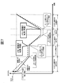
- FIG. 7 is an explanatory diagram showing a state of balancing control for resuming balancing using information at the time of balancing when balancing is interrupted.
- the horizontal axis is time, and the vertical axis is SOC.
- the SOC change of the large capacity unit cell based on the individual difference is shown by a solid line, and the SOC change of the small capacity unit cell is shown by a broken line.
- the vehicle is traveling in the section (T1, T2) and the section (T3, T4), and the assembled battery control means 150 (described as system in the figure) is operating. Further, it is assumed that the section (T5, T6) is being charged and the assembled battery control means 150 is operating.
- the assembled battery control means 150 is stopped in the sections (T2, T3) and sections (T4, T5) between them. It is assumed that the initial state at time T1 is a state where charging is finished. The balancing control is executed at a time when the assembled battery control means 150 is operating.
- the single cell having a smaller capacity indicated by the broken line is a solid line.
- the SOC is higher than that of the large-capacity unit cell shown, and the SOC varies as indicated by arrows. It is not preferable to leave the variation in a region where the SOC is high in this way, because the capacity variation increases due to deterioration of the unit cell. Therefore, when the SOC is high, for example, when the average SOC of the plurality of single cells 111 constituting the single cell group 112 is 75% or more, balancing is started. Assume that balancing is newly started at time T1.
- the assembled battery control means 150 interrupts the balancing operation, stores the balancing information at that time in the storage device 127, and then stops the operation.
- the information stored in the storage device 127 is, for example, an elapsed time (discharge time) from the start of balancing, or a remaining adjustment time obtained by subtracting the elapsed time from the discharge time required for SOC adjustment calculated for each cell. .
- the assembled battery control means 150 reads from the storage device 127 halfway information at the time of balancing interruption, and resumes balancing using the information.
- the assembled battery control means 150 stores in the storage device 127 balancing information at the time of interruption, that is, the elapsed time from the start of balancing, or the remaining time for each cell. Then stop the operation.
- the single battery with a small capacity indicated by a broken line has a faster SOC decreasing rate than the single battery with a large capacity indicated by a solid line. The relationship is reversed from that at time T1.
- the power storage device 100 is connected to the charger 420 at time T5 and the assembled battery control unit 150 resumes operation, the balancing intermediate information interrupted at time T4 is read from the storage device 127 again.
- Fig. 7 shows an ideal state.
- the variation in SOC may be deteriorated due to a change in the battery state or the like.
- the balancing information does not match the actual battery state, which causes a deterioration in SOC variation.
- FIG. 8 it is assumed that balancing is newly started to eliminate the SOC variation of the arrows that existed at time T1.
- intermediate information at the time of balancing interruption is stored in the storage device 127, and when the keys are turned on at times T3, T5, etc.
- the method of continuing the balancing by taking over the intermediate information at the time of balancing interruption is based on the premise that the SOC of each unit cell does not change between the balancing interruption and the restart.
- the battery state has changed for some reason while the assembled battery control means 150 is stopped from time T2 to time T3, when the SOC of the cell when the balancing is resumed at time T3, the balancing is interrupted at time T2. It will be different from the SOC. Therefore, as shown in the state at time T5, it is impossible to eliminate the SOC variation between the single cells in the high SOC state.
- any information of the old state information of the unit cell by balancing at the time of the previous battery activation stored in the storage device 127 and the new state information of the unit cell obtained by the current battery activation is used.
- the assembled battery control means 150 is provided with a determination unit that determines whether or not Then, when starting balancing in the current battery activation, the determination unit determines whether the balancing is performed based on the old state information or the new state information. When the battery is started this time, the assembled battery control unit 150 reacquires the current SOC of each unit cell 111 from the unit cell control unit 121, and based on the re-acquired SOC, each unit cell 111 necessary for SOC adjustment.
- the discharge time through the bypass resistor 122 is calculated.
- the determination unit compares the stored determination condition with a predetermined amount more than a predetermined amount from the previous balancing interruption, the determination unit calculates the discharge end condition calculated from the current SOC.
- the information is overwritten on the storage device 127. Otherwise, balancing is resumed using the halfway information at the time of balancing interruption stored in the storage device 127. In this way, the battery pack control means 150 is stopped by selecting any one of the current state information of each unit cell 111 and the old state information of each unit cell 111 at the time of the previous balancing interruption, and performing the balancing control. Even if there is a change in the battery state or the like, it is possible to satisfactorily equalize the SOC.
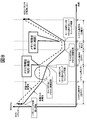
- FIG. 9 shows which one of the old state information of the unit cell 111 by balancing at the time of the previous battery activation stored in the storage device 127 and the new state information of the unit cell 111 obtained at the time of the current battery activation is used. It is explanatory drawing which shows the example of balancing control at the time of determining.
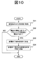
- FIG. 10 is a flowchart illustrating an example of processing executed before starting balancing control when the battery is activated.
- Balancing is newly started at time T1, and when the key is turned off at time T2, the assembled battery control unit 150 interrupts the balancing operation, stores the information during the balancing in the storage device 127, and then stops the operation. Until this is done, the process is the same as in FIG. Next, when the vehicle is keyed on at time T3 and the assembled battery control means 150 operates, the assembled battery control means 150 first executes the processing shown in FIG. That is, in step 31, the OCV of the unit cell 111 is acquired, and then the SOC is obtained using the relationship shown in FIG. Next, proceeding to step 32, it is determined whether or not balancing control should be newly started based on the latest SOC information acquired this time, or whether or not suspended balancing should be resumed using the halfway information stored in the storage device 127. I do.
- the balancing control is newly started based on the newly acquired SOC of the unit cell 111.
- the maximum SOC value may be determined in consideration of the SOC region in which the deterioration of the battery is promoted and the SOC region to which the user charges with PHEV or EV, but may be set to 70% or more, for example. .
- is equal to or greater than a predetermined value may be set using the SOC-OCV characteristic of FIG.
- the balancing capacity is a product ⁇ SOC ⁇ Qmax of the difference ⁇ SOC between the SOC of the unit cell and the target SOC and the full charge capacity Qmax of the unit cell.
- balancing is continued using information at the time of interruption, environmental changes, changes in battery characteristics, and errors in balancing accuracy increase during that time, and unevenness is not performed correctly and dispersion increases. This is because there is a risk of it. If the balancing process is nearing completion based on this criterion, it is possible to prevent the deterioration of the balancing accuracy and increase the variation by starting a new balancing process.
- How much time (days) should elapse after the last balancing start depends on how long it takes to complete the balancing of all balancing capacity, how often the user uses the vehicle, and the self-discharge characteristics of the battery It may be determined in consideration of variations in dark current and variations in dark current of the circuit to which each unit cell is connected. For example, when 30 days have passed since the start of the previous balancing operation, it was acquired in step 31. A new balancing may be started based on the SOC.
- the predetermined time may be determined in consideration of the polarization characteristics of the battery and its variation, for example, several minutes to several hours. This is because when the standing time is short, the state of the battery is not stable due to the influence of polarization or the like. This is because if balancing is newly started at this time, inaccurate battery variations may be detected. According to this standard, it is possible to prevent the start of balancing based on the SOC obtained when the battery state is not stable, and it is possible to prevent deterioration in balancing accuracy and increase in variation.
- the balancing is not newly started, and the intermediate information stored in the storage device 127 is used. To resume balancing.
- step 32 determines whether balancing is newly started based on the information newly acquired in step 31. If the determination in step 32 is NO, that is, when balancing is newly started based on the information newly acquired in step 31, the process proceeds to step 33, and the newly obtained SOC is used. Then, the discharge end condition is calculated according to the above formulas (1) and (2). In step 34, the calculated discharge end condition is transmitted to each unit cell control means 121.
- the unit cell control means 121 receives the transmitted discharge end condition in step 21 according to the procedure shown in FIG. Thereafter, as described above, the bypass switch 123 is controlled to open and close until each cell 111 satisfies the discharge termination condition, and the discharge through the bypass resistor 122 is continued.
- the continuous restart balancing by selecting one of the new / old battery status information and performing the balancing, the variation due to the battery status change, the bypass resistance error, etc. is deteriorated. Can be suppressed. Further, when the battery state becomes better (high SOC, etc.), the capacity adjustment condition can be newly acquired, and good balancing can be performed.
- each of the above-described configurations, functions, processing units, processing means, and the like may be realized by hardware by designing a part or all of them with, for example, an integrated circuit.
- Each of the above-described configurations, functions, and the like may be realized by software by interpreting and executing a program that realizes each function by the processor.
- Information such as programs, tables, and files for realizing each function can be stored in a recording device such as a memory, a hard disk, or an SSD (Solid State Drive), or a recording medium such as an IC card, an SD card, or a DVD.
Landscapes
- Engineering & Computer Science (AREA)
- Power Engineering (AREA)
- Manufacturing & Machinery (AREA)
- Chemical & Material Sciences (AREA)
- Chemical Kinetics & Catalysis (AREA)
- Electrochemistry (AREA)
- General Chemical & Material Sciences (AREA)
- Life Sciences & Earth Sciences (AREA)
- Sustainable Development (AREA)
- Sustainable Energy (AREA)
- Transportation (AREA)
- Mechanical Engineering (AREA)
- Charge And Discharge Circuits For Batteries Or The Like (AREA)
- Secondary Cells (AREA)
Abstract
バランシング制御が中断された場合でも、良好にバランシングを実施する。 記憶装置に記憶された前回のバランシングによる電池セル情報(旧状態情報)と、今回起動時に取得した電池セル情報(新状態情報)とのいずれを利用するかを条件によって選択して、バランシング制御を行う。
Description
本発明は、リチウム二次電池やニッケル水素電池、鉛電池、電気二重層キャパシタなどの蓄電手段を用いた電源装置に搭載する電池制御回路に関する。
電気自動車(EV)やプラグインハイブリッド自動車(PHEV)、ハイブリッド自動車(HEV)に搭載する蓄電装置では、複数の蓄電器を直列に接続して蓄電部を構成するのが一般的である。ここで、蓄電器間に容量のバラツキや自己放電バラツキといった蓄電器の個体差がある場合、蓄電装置が備える各蓄電器の充電状態(State of Charge:SOC)にバラツキが生じてしまう。このバラツキが発生すると、複数個の蓄電器の中で最もSOCの高い蓄電器を基準に充電制御が行われ、SOCが最も低い蓄電器を基準に放電制御が行われるため、蓄電部としての利用可能なエネルギーが小さくなってしまう。また、PHEV若しくはEVのようにSOCの利用範囲が広範囲になることが想定される場合、SOCが高い若しくは低い状況では、蓄電器の劣化が進行しやすくなるため、SOCが高過ぎる場合はSOCを低下させる、若しくはSOCが低過ぎる場合は、それ以上のSOCの低下を防ぐ等の対策が必要である。そこで、複数の蓄電器を直列に接続した場合に生じ得る蓄電器間のSOCのバラツキを解消するために、蓄電器に並列に接続されたバイパス抵抗とバイパススイッチから構成されるバランシング回路と、蓄電器の状態を監視する蓄電器制御手段とを実装し、蓄電器制御手段が電圧のバラツキ量に基づいてバランシング回路のバイパススイッチを制御する方法が提案されている。即ち、電圧が高い蓄電器を強制的に放電し、電圧の均等化を行うバランシング方法である。
特開2004-31012号公報には、組電池の全セルの充電容量の平均値が、セルの充電容量SOC-開放電圧Vo特性における傾き|ΔVo/ΔSOC|が所定値以上の範囲にある場合のみ、組電池の各セルの容量調整条件を決定し、その条件に従って容量調整を行うこと、及び容量調整が中断されたときは、容量調整の残り情報を記憶手段に記憶し、容量調整が可能になったら記憶手段から容量残り情報を読み出して容量調整を再開することが記載されている。
PHEVやEVに搭載される蓄電器のように広範なSOCで利用される蓄電器の場合、高SOC状態で蓄電器間にSOCバラツキが存在する状態で放置されると、劣化バラツキが懸念される。一方、OCV(Open Circuit Voltage:開回路電圧)-SOCカーブの電池特性上、高SOC域で電池情報を取得し、バランシングは継続して終了まで行うのが望ましい。すなわち、バランシングが中断されたときは、中断された状態からバランシングを継続再開し、起動ごとに新規にバランシングを開始することはしない。しかし、常に中断された状態からの継続バランシングを実施すると、電池状態の変化、バイパス抵抗誤差などによって、バラツキが悪化する場合がある。また、より劣化バラツキが懸念される電池状態(高SOC等)となった場合でも新規に容量調整条件を取得することができず、良好なバランシングを行うチャンスを逃してしまうという問題がある。
本発明では、蓄電器の情報を用いてバランシングを実施する際に、記憶装置に記憶されている前回のバランシング中断時の情報(旧状態情報)と、今回起動時に取得した蓄電器の情報(新状態情報)のいずれを利用するかを選択し、選択した情報に基づいてバランシングを実行する。
すなわち、本発明の蓄電器制御回路は、記憶装置を有し、直列接続された複数の蓄電器の状態監視及びバランシング制御を行う制御手段を備え、制御手段は、複数の蓄電器の状態をもとに計算したバランシング制御のための情報を前記記憶装置に記憶し、記憶装置に記憶された情報に基づいてバランシング制御を行う。バランシング制御が中断されたとき、制御手段はバランシングに関する中断時の情報を記憶装置に記憶し、中断後にバランシング制御を開始するに際し、複数の蓄電器の状態に関する最新の情報を取得し、記憶装置に記憶された中断時の情報に基づいてバランシング制御を再開するか、最新の情報に基づいてバランシングを新規に開始するかを予め決められた条件に基づいて選択し、バランシングを新規に開始する場合には、取得した最新の情報をもとに計算したバランシング制御のための情報を記憶装置に記憶する。
より具体的な一態様においては、直列接続されて蓄電部を構成する複数の蓄電器群に対応して複数の蓄電器制御手段が設けられ、各蓄電器制御手段は対応する蓄電器群に属する個々の蓄電器の状態の監視及びバランシング制御を行う。監視する蓄電器の状態には、電圧、SOC及び温度がある。蓄電部制御手段は、複数の蓄電器制御手段からの情報をもとに複数の蓄電器制御手段を制御する。蓄電部制御手段は、充電状態が所定の充電状態よりも高い蓄電器が存在する蓄電器群の蓄電器制御手段に、当該電器制御手段からの情報をもとに計算したバランシング制御のための情報を送る。蓄電器制御手段は記憶装置を有し、受信した情報を記憶装置に記憶し、記憶装置に記憶された情報に基づいてバランシング制御を行う。
バランシング制御が中断されたとき、蓄電器制御手段はバランシングに関する中断時の情報を記憶装置に記憶する。蓄電部制御手段は、その後、再びバランシング制御を行うとき、各蓄電器制御手段からそれぞれの蓄電器群に属する個々の蓄電器の状態に関する最新の情報を取得する。そして、記憶装置に記憶された中断時の情報に基づいてバランシング制御を再開するか、最新の状態に基づいてバランシングを新規に開始するかを決定する。バランシングを新規に開始する場合には、蓄電部制御手段は、取得した最新の情報をもとに新たに計算したバランシング制御のための情報を対応する蓄電器制御手段に送り、蓄電器制御手段は受信した情報を記憶装置に記憶する。蓄電器制御手段は、いずれの場合においても、記憶装置に記憶されている情報に基づいてバランシング制御を実行する。新旧いずれの情報に基づいてバランシングを行うかの判定条件は、蓄電部制御手段内に保持する。
本発明によると、良好にバランシングを実施することができる。
上記した以外の、課題、構成及び効果は、以下の実施形態の説明により明らかにされる。
以下、本発明の実施例を図面に基づいて説明する。以下の実施例では、プラグインハイブリッド自動車(PHEV)の電源を構成する蓄電装置に対して本発明を適用した場合を例に挙げて説明するが、本発明は、ハイブリッド自動車(HEV)、電気自動車(EV)などの乗用車やハイブリッド鉄道車両といった産業用車両の電源を構成する蓄電装置の蓄電器制御回路にも適用できる。
また、以下の実施例では、蓄電部を構成する蓄電器にリチウムイオン電池を適用した場合を例に挙げて説明するが、蓄電器としては、他にもニッケル水素電池や鉛電池、電気二重層キャパシタ、ハイブリッドキャパシタなどを用いることもできる。なお、以下の実施例中の組電池は蓄電部に、単電池は蓄電器に、単電池群は蓄電器群に、単電池制御手段は蓄電器制御手段に、組電池制御手段は蓄電部制御手段にそれぞれ対応する。単電池制御手段及び組電池制御手段は、回路基板上の集積回路として実現される。また、単電池制御手段と組電池制御手段を合わせたものは、制御手段に対応する。
図1に、本発明の一実施例におけるPHEVの蓄電装置の構成例を示す。
最初に蓄電装置100の構成について説明する。蓄電装置100は、複数の単電池111から構成される組電池110、単電池111の状態を監視する単電池管理手段120、蓄電装置100に流れる電流を検知する電流検知手段130、組電池110の総電圧を検知する電圧検知手段140、及び組電池110の制御を行う組電池制御手段150を備える。組電池制御手段150は、単電池管理手段120から送信される単電池111の電池電圧や温度、電流検知手段130から送信される蓄電装置100に流れる電流値、電圧検知手段140から送信される組電池110の総電圧値が入力されており、入力された情報をもとに組電池110の状態検知などを行う。また、組電池制御手段150が行う処理の結果は、単電池管理手段120や車両制御手段200に送信される。
車両制御手段200は、組電池制御手段150の情報をもとに、蓄電装置100とリレー300,310を介して接続されるインバータ400及びリレー320,330を介して接続される充電器420の制御を行う。車両走行中には、蓄電装置100はインバータ400と接続され、組電池110が蓄えているエネルギーをもとに、モータジェネレータ410を駆動する。充電の際には、蓄電装置100は充電器420と接続され、家庭用の電源又は電気スタンドからの電力供給で充電される。
組電池110は、電気エネルギーの蓄積及び放出(直流電力の充放電)が可能な複数の単電池111(リチウムイオン電池)を電気的に直列に接続して構成される。1つの単電池111は、出力電圧が3.0~4.2V(平均出力電圧:3.6V)であり、単電池111の開回路電圧(OCV:Open Circuit Voltage)とSOCには図3に示すような相関関係があるとした場合を例に挙げて説明するが、これ以外の電圧仕様のものでも構わない。
組電池110を構成する単電池111は、状態の管理・制御を行う上で、所定の単位数にグループ分けが行われている。グループ分けされた単電池111は、電気的に直列に接続され、単電池群112a,112bを構成する。所定の単位数は、例えば1個、4個、6個‥‥というように、等区分とする場合もあれば、4個と6個とを組み合わせる、というように、複合区分とする場合もある。また、高電位側の単電池群112aと低電位側の単電池群112bはスイッチとヒューズが直列接続された保守・点検用のサービスディスコネクタ180を介して、電気的に直列に接続される。
組電池110を構成する単電池111の状態を監視する単電池管理手段120は、複数の単電池制御手段121a,121bから構成されており、上記のようにグループ分けされた単電池群112a,112bに対して1つの単電池制御手段121a,121bが割り当てられている。単電池制御手段121a,121bは割り当てられた単電池群112a,112bからの電力を受けて動作し、単電池群112a,112bを構成する単電池111の状態を監視及び制御する。
本実施例では、説明を簡単にするために、組電池110は合計8個の単電池111を備え、4個の単電池111を電気的に直列に接続して2つの単電池群112a,112bを構成し、さらに単電池群同士をサービスディスコネクタ180を介して、電気的に直列に接続するものとした。また、単電池群112a,112bには、単電池111の状態を監視するための単電池制御手段121a,121bがそれぞれ設置されている。
組電池制御手段150には、単電池管理手段120から出力される単電池111の電池電圧や温度の計測値、更には単電池111が過充電若しくは過放電であるかの診断結果や単電池管理手段120に通信エラーなどが発生した場合に出力される異常信号と、電流検知手段130からの電流値と、電圧検出手段140から出力される組電池110の総電圧値と、上位の制御装置である車両制御手段200から出力された信号とを含む複数の信号が入力されている。ここで、入力された情報と、予め記憶されている単電池111の内部抵抗や、SOCとOCVの関係(図3)に基づいて、単電池111のSOC演算や、後に説明する放電終了条件を含んだバランシング制御を行うための演算、充放電量を制御するための演算などを実行する。そして、その演算結果やこれに基づく指令を、単電池管理手段120や車両制御手段200に出力する。
組電池制御手段150と単電池管理手段120は、フォトカプラのような絶縁素子170を介して、信号通信手段160により信号の送受信を行う。絶縁素子170を設けるのは、組電池制御手段150と単電池管理手段120とで、動作電源が異なるためである。すなわち、単電池管理手段120は、組電池110から電力をうけて動作するのに対して、組電池制御手段150は、車載補機用のバッテリ(例えば14V系バッテリ)を電源として用いている。絶縁素子170は、単電池管理手段120を構成する回路基板に実装してもよいし、組電池制御手段150を構成する回路基板に実装してもよい。もちろん、単電池管理手段120と組電池制御手段150を1つの回路基板に実装してもよい。なお、システム構成によっては、絶縁素子170を省略することも可能である。
本実施例における組電池制御手段150と、単電池制御手段121a,121bとの通信手段について説明する。単電池制御手段121a,121bは、それぞれが監視する単電池群112a,112bの電位の高い順に従って直列に接続されている。組電池制御手段150が送信した信号は、絶縁素子170を介して、信号通信手段160により単電池制御手段121aに入力される。単電池制御手段121aの出力と単電池制御手段121bの入力との間も同様に、信号通信手段160により接続され、信号の伝送を行う。なお、本実施例では、単電池制御手段121aと単電池制御手段121b間は、絶縁素子170を介していないが、絶縁素子170を介していてもよい。そして、単電池制御手段121bの出力は、絶縁素子170を介して、組電池制御手段150の入力を経て、信号通信手段160により伝送される。このように、組電池制御手段150と、単電池制御手段121aと単電池制御手段121bは、信号通信手段160によりループ状に接続されている。このループ接続は、デイジーチェーン接続あるいは数珠繋ぎ接続若しくは芋づる式接続と呼ぶ場合もある。なお、ここでは単電池制御手段121aと単電池制御手段121bがループ状に接続された例を示しているが、必ずしもループ状である必要はなく、組電池制御手段150と単電池制御手段121aと単電池制御手段121bが接続されていればどのような形態であってもよい。
図2に、本実施例における単電池制御手段121a,121bの回路構成を示す。単電池制御手段121a,121bは、バイパス抵抗122とバイパススイッチ123から構成されるバランシング回路、バイパススイッチ123を駆動するBSW駆動回路125、管理対象とする単電池111の電池電圧を計測する電圧検出回路124、単電池制御手段121a,121bを動作させるための電源126、組電池制御手段150からの情報をもとに単電池制御手段121a,121bの制御を行う制御回路128、組電池制御手段150又は隣り合う単電池制御手段121との間で信号の送受信を行う信号入出力回路129を有する。
EEPROMなどの記憶装置127には、予め計測された各単電池の容量、組電池制御手段150により演算されたバランシングのための情報等が記憶される。詳細は後述するが、目標SOC値に到達するまでに必要な各単電池のバイパス抵抗122を介した放電時間が記憶される。バランシング動作が完了前に中断された場合には、記憶装置127にバランシング中断時の状態、例えばバランシング開始からの経過時間(放電時間)、バランシング完了までの残り時間、残バランシング容量、単電池毎にバランシングが完了したか否かの情報、バランシング開始時の電池温度等が書き込まれる。なお、ここでは単電池制御手段121a,121bに記憶装置127を含む構成を示したが、例えば組電池制御手段150が含む記憶装置に上記情報を記憶する構成であってもよい。
制御回路128は、組電池制御手段150から送信された電圧取得命令やバランシング制御に関する情報を、信号入出力回路129を介して受信し、電圧検出回路124で検出された電池電圧やこれに基づく情報を信号入出力回路129に出力する。そして、制御回路128は、検出された電池電圧と、記憶装置127に記憶されている情報をもとにBSW駆動回路125の制御を行う。
次に、バランシング回路の放電手段について説明する。放電手段は、単電池群112を構成する単電池111の中で、SOCの高い単電池111を、バイパス抵抗122とバイパススイッチ123から構成されるバランシング回路を利用して、放電する手段である。つまり、放電の対象となった単電池111に並列に接続されたバイパススイッチ123をオンにし、バイパス抵抗122を用いることで、単電池111を強制的に放電させ、目標となるSOC(目標SOC)まで低下させる。ここで、目標SOCとは、前述したように、組電池110を構成する複数の単電池111のうち何れかが、過充電となってしまった場合、あるいは単電池群112を構成する単電池111のSOCに許容限度を超えたバラツキが生じている場合などに、これを解消するために設定される所定のSOCであり、詳細は後述する。なお、本実施例で説明する放電終了条件は、下記に限定されるものではない。
放電終了条件は、単電池111の放電に必要な時間を算出し、その結果に基づいて決定する。所定の放電量を確保するのに必要な時間を算出し、算出した時間が経過したら放電を終了とする。このため、単電池制御手段121に、算出した時間が経過したかを判断するために、タイマーなどの時間計測手段を設置する。なお、放電終了条件を決定するための算出式の説明は、単電池111の個数8個をN個、単電池群112の個数2個をM個、単電池群112を構成する単電池111の個数4個をL個(=N/M)と置き換えて、行うものとする。
まず、組電池無負荷状態におけるすべての単電池111のOCV測定結果から、SOCとOCVの相関関係に基づいてSOCを推定し、各単電池111のSOCと目標SOCとの差ΔSOCを以下の式(1)に従って求める。
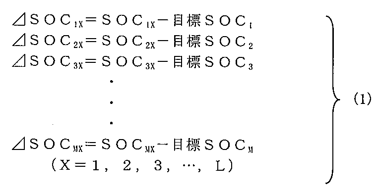
求めたΔSOCより、調整に必要な時間tを以下の式(2)から求める。
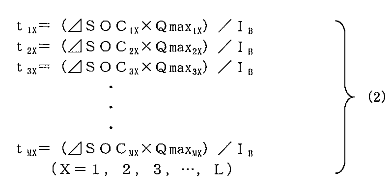
ここで、Qmaxは、単電池111の満充電容量[Ah]を、IBは、バイパス抵抗に流れるバイパス電流 [A]を、Xは単電池群を構成する単電池111の番号を表す。上記調整時間tが、それぞれの単電池の放電終了条件となる。式(2)の結果に基づいて、放電対象の単電池111を放電させ、所定の放電量を確保するのに必要な時間が経過したとき、放電を終了する。なお、調整時間tの代わりに各単電池111のバランシング容量ΔSOC×Qmax[Ah]を求めておき、そこから単位時間毎に放電量[Ah]を減算し、バランシング容量が0[Ah]以下となることを放電終了条件としてもよい。
放電手段によるSOCの変化の一例を図4により説明する。図の例では、放電手段は、単電池群112を構成する単電池111の電池電圧が、単電池群112ごとに設定された目標値と、全て一致するようにバランシング回路を利用してSOCの高い単電池111を放電させる。図示した例の場合、単電池群112aの目標SOCはA、単電池群112bの目標SOCはBである。従って、図4のように単電池群112を構成する単電池111の中で放電対象となった単電池111のSOCが低下し、単電池群112を構成する全ての単電池111のSOCが目標値と一致したとき放電を終了する。なお、全ての単電池群112に設定される目標SOCを、最も低い目標SOC、図4の場合にはBに合わせてバランシングを行うと、組電池110を構成する全ての単電池111のSOCをBに一致させることができる。
続いて、本実施例における組電池制御手段150の放電終了条件を決定する動作の流れを、図5のフローチャートに基づいて説明する。図5は、車両の走行中又は充電中における組電池制御手段150の動作フロー図である。
まず、ステップ11で、全ての単電池111の無負荷時若しくは電流が微弱で無負荷時とみなせる場合の電圧(OCV)を取得する。OCVは図3の関係を用いてSOCに変換される。次にステップ12へ進み、単電池群112を構成する単電池111のSOCと、目標とするSOCにバラツキがあるかを判定する。バラツキがあると判定されれば、ステップ13へ進む。
ステップ13では、バイパス抵抗122とバイパススイッチ123からなるバランシング回路を利用した放電手段の放電終了条件を決定し、ステップ14で放電終了条件を単電池制御手段121に送信する。
次に、本実施例における単電池制御手段121の放電手段の動作の流れを、図6のフローチャートに基づいて説明する。図6は、車両の走行中若しくは充電中における単電池制御手段121の動作を説明するフローチャートである。
まず、ステップ21で単電池制御手段121は、組電池制御手段150から送信された放電終了条件を受信し、受信した放電終了条件を記憶装置127に記憶する。次に、ステップ22へ進み、バイパス抵抗122とバイパススイッチ123からなるバランシング回路を利用して、放電対象となった単電池111からの放電を開始する。なお、放電は必ずしも連続である必要はなく、パルス信号やデューティ制御などを用いて断続的に行ってもよい。その場合、調整時間tもしくは調整放電量ΔSOC×Qmaxは、放電している時間や放電量のみを積算して判定する。
ステップ23では、単電池群112を構成する全ての単電池の放電が終了したかを判定する。終了したと判定されれば、単電池制御手段121は処理を終了する。ステップ23の判定で全ての単電池111の放電が終了していないと判定された場合には、ステップ24へ進み、放電終了条件を満たした単電池111があるかを判定する。放電が終了した単電池111があれば、ステップ25に進み、放電が終了した単電池111から順番にバイパススイッチ123をオフにする。その後、ステップ23に戻り、単電池群112を構成する全ての単電池111の放電が終了するまで処理を続ける。
以上は、一般的なバランシング制御の説明である。ここで、組電池110を構成している各単電池111の電池容量には個体差によって多少のバラツキがあるが、組電池110の充電直後など高SOC領域においてSOCバラツキがある状態で長時間使用・放置すると、電池が劣化することにより更に容量バラツキが拡大する。本実施例では、高SOC領域での劣化による容量バラツキ拡大を防ぐためにバランシング制御を行う。例えば、高SOC領域において、SOCの値が最低の単電池を基準に、その単電池のSOCより0.5%以上高いSOCを有する単電池をバランシング対象単電池として選定する。そして、バランシング対象単電池のSOCを最低SOCに一致させるために必要な放電量、及び放電時間を上記の式(1)、(2)によって計算し、計算によって決定された放電時間だけ対応する単電池111に付随するバイパススイッチ123をオンにし、バイパス抵抗122を介して放電させる。こうして、バランシング後の単電池SOCのバラツキを0.5%に抑える。バランシングの完了前に車両がキー・オフ(メインスイッチ・オフ)されるとバランシングが中断されるが、その時は、バランシング中断時の途中情報、すなわちバランシング開始からの経過時間、あるいは各単電池の残り放電時間、残容量などを記憶装置127に記憶し、組電池制御手段150を停止する。次回、車両がキー・オン(メインスイッチ・オン)されると、記憶装置127から前回中断時に記憶したバランシング途中情報を読み出し、その情報に基づいてバランシングを再開継続する。
図7は、バランシングが中断されたとき、中断時の情報を用いてバランシングを再開するバランシング制御の様子を示す説明図である。横軸は時間、縦軸はSOCである。図には、個体差に基づく容量大の単電池のSOC変化を実線で示し、容量小の単電池のSOC変化を破線で示した。説明を簡単にするため、区間(T1,T2)、区間(T3,T4)は車両が走行中であり、組電池制御手段150(図ではシステムと記述)が動作しているものとする。また、区間(T5,T6)は充電中であり、組電池制御手段150が動作しているものとする。その間の区間(T2,T3)及び区間(T4,T5)では、組電池制御手段150は停止しているものとする。時刻T1の初期状態は、充電が終了した状態であるとする。バランシング制御は、組電池制御手段150が動作中の時間に実行される。
時刻T1のSOCから分かるように、全ての単電池111は直列接続されていて同じ充電電流で充電されるため、充電終了後の初期状態では、破線で示す容量の小さい単電池の方が実線で示す容量の大きな単電池よりSOCが高くなり、SOCに矢印で示すようなバラツキが生じている。このようにSOCが高い領域でバラツキの存在を放置すると、単電池の劣化により容量バラツキが拡大するため好ましくない。そこで、SOCが高いとき、例えば単電池群112を構成する複数の単電池111の平均SOCが75%以上のとき、バランシングを開始する。いま、時刻T1で新規にバランシングを開始したとする。バランシングの開始に当たっては、前述のように、組電池110が無負荷とみなせる状態で測定したOCVから換算して得た各単電池111のSOCを目標値に調整して均一化するのに必要な放電量、及びその放電量をバイパス抵抗122を介して放電させるのに必要な時間を計算し、それを記憶装置127(図ではメモリと記述)に記憶する。その後、記憶した単電池毎の放電時間に基づいてバランシング制御を開始する。
時刻T2で車両が停止し、キー・オフされると、組電池制御手段150はバランシング動作を中断させ、そのときのバランシング情報を記憶装置127に記憶させてから、動作を停止する。記憶装置127に記憶する情報は、例えば、バランシング開始からの経過時間(放電時間)、あるいは単電池毎に計算されたSOC調整に必要な放電時間からその経過時間を差し引いた残りの調整時間である。時刻T3で車両が再びキー・オンされ、組電池制御手段150が動作すると、組電池制御手段150は記憶装置127からバランシング中断時の途中情報を読み出し、その情報を利用してバランシングを再開する。再び時刻T4に車両が停止し、キー・オフされると、組電池制御手段150は中断時のバランシング途中情報、すなわちバランシング開始からの経過時間、あるいは単電池毎の残り時間を記憶装置127に記憶させてから動作を停止する。同じ放電電流では、破線で示した容量の小さい単電池の方が実線で示した容量の大きな単電池よりSOCの低下速度が速く、時刻T4では容量の大きな単電池と小さな単電池のSOCの大小関係が時刻T1のときと逆転している。更に、時刻T5で蓄電装置100が充電器420に接続され、組電池制御手段150が動作を再開すると、再び記憶装置127から時刻T4で中断したバランシング途中情報を読み出す。そして、その情報を利用して中断した状態からバランシングを再開する。その結果、充電終了時である時刻T6には、高SOC領域で容量の異なる単電池のSOCがそろい、単電池の劣化による容量バラツキの拡大が防止される。
図7には理想的な状態を示した。しかし、常にバランシング途中情報を利用してバランシングを継続再開すると、電池状態の変化などによって、SOCのバラツキが悪化する場合がある。また電池が交換された場合も、バランシング途中情報が実際の電池状態と整合しないため、SOCのバラツキを悪化させる原因となる。例えば、図8に示すように、時刻T1に存在していた矢印のSOCバラツキを解消すべく新規にバランシングを開始したとする。あとは、図7の場合と同様に、時刻T2,T4などでキー・オフされたときにバランシング中断時の途中情報を記憶装置127に記憶しておき、時刻T3,T5などのキー・オン時に、記憶装置127に記憶されたバランシング途中情報を用いてバランシングを再開したとする。バランシング中断時の途中情報を引き継いでバランシングを継続する方法は、バランシング中断時と再開時で各単電池のSOCが変化しないことが前提である。ここで、時刻T2からT3の組電池制御手段150停止中に、何らかの原因で電池状態が変化したとすると、時刻T3でバランシングを再開したときの単電池のSOCが時刻T2でバランシングを中断したときのSOCと異なってしまう。そのため、時刻T5の状態に示すように、高SOC状態で単電池間のSOCバラツキを解消することができない。
そこで、本実施例では、記憶装置127に記憶された前回のバッテリ起動時のバランシングによる単電池の旧状態情報と、今回のバッテリ起動によって得られた単電池の新状態情報のいずれの情報を用いるかを判定する判定部を組電池制御手段150に設けた。そして、今回のバッテリ起動においてバランシングを開始するにあたり、そのバランシングを、旧状態情報に基づいて行うか、新状態情報に基づいて行うかを判定部によって決定する。今回のバッテリ起動時、組電池制御手段150は、単電池制御手段121から現在の各単電池111のSOCを再取得し、再取得したSOCに基づいて、SOC調整に必要な各単電池111のバイパス抵抗122を介した放電時間を計算する。判定部は、格納されている判定条件と照合して、電池のSOCが前回バランシング中断時から所定量以上乖離していると推定される場合には、現在のSOCから計算された放電終了条件の情報を記憶装置127に上書きする。そうでなければ、記憶装置127に記憶されているバランシング中断時の途中情報を利用してバランシングを再開させる。このように、現在の各単電池111の状態情報と、前回バランシング中断時の各単電池111の旧状態情報のいずれかを選択してバランシング制御を実施することにより、組電池制御手段150停止中に電池状態などの変化があっても、良好にSOCの均等化を行うことが可能になる。
図9は、記憶装置127に記憶された前回のバッテリ起動時のバランシングによる単電池111の旧状態情報と、今回のバッテリ起動時に得られた単電池111の新状態情報とのいずれを用いるかの判定を行った場合のバランシング制御の例を示す説明図である。図10は、バッテリ起動時に、バランシング制御を開始する前に実行する処理の一例を示すフローチャートである。
時刻T1にバランシングを新規に開始し、時刻T2でキー・オフされたとき、組電池制御手段150がバランシング動作を中断し、そのときのバランシング途中情報を記憶装置127に記憶してから動作を停止するまでは、図7の場合と同じである。次に、時刻T3で車両がキー・オンされ、組電池制御手段150が動作すると、組電池制御手段150は最初に図10に示した処理を実行する。即ち、ステップ31において、単電池111のOCVを取得し、それから図3の関係を用いてSOCを求める。次にステップ32に進み、今回取得した最新のSOC情報に基づいてバランシング制御を新規に開始すべきか、記憶装置127に記憶されているバランシングの途中情報を用いて中断したバランシングを再開すべきかの判定を行う。
この判定において、以下のような条件を満たす場合には、新たに取得した単電池111のSOCに基づいて新規にバランシング制御を開始する。
(1)新規に取得した各単電池SOCのうち、最高SOCが予め定めた所定値以上のとき。
最高SOCの値は、電池の劣化が促進されるSOC領域や、PHEVやEVでユーザーがどの程度のSOC領域まで充電するかを勘案して決定すればよいが、例えば70%以上とすればよい。
これは、SOCが高い領域では電池の劣化が激しいため、SOCがそのような高い領域にある場合には、各単電池のSOCを均等化しSOCバラツキを避けるのが好ましいためである。逆に、SOCが低いところでSOCを均等化しても、充電によってSOCが高い状態になると均等化が崩れる。従って、最高SOCが所定値以上の場合には、最新の情報に基づいてバランシングを実行する。この条件により、SOCが高い領域でのバラツキを検知してバランシングするため、電池劣化を良好に抑えることができる。なお、SOCを高精度に検出するために、図3のSOC-OCV特性を用いて、傾き|ΔOCV/ΔSOC|が所定値以上という条件としてもよい。
(2)残バランシング容量/開始時の全バランシング容量が所定値以下のとき。
バランシング容量とは、単電池のSOCと目標SOCとの差ΔSOCと、単電池の満充電容量Qmaxとの積 ΔSOC×Qmax である。前回キー・オフ時までに全バランシング容量のどの程度が完了した場合に、新規にバランシングを開始すべきかは、全バランシング容量のバランシング完了までにかかる時間や、ユーザーが車両を使用する頻度、電池の自己放電特性のバラツキ、各単電池が接続されている回路の暗電流のバラツキ等を考慮して決定すればよいが、例えば全バランシング容量の80%が完了している場合に、ステップ31で取得したSOCに基づいて新規にバランシングを開始するようにすればよい。
これは、中断時の情報を用いてバランシングを継続し続けると、その間の環境の変化、電池特性の変化、バランシング精度の誤差が増加してしまい、均等化が正しく行われずにバラツキが拡大してしまう恐れがあるためである。この判定基準に基づいて、バランシング工程が完了に近づいていた場合には、新規にバランシングを開始することでバランシング精度の悪化、バラツキ拡大を防ぐことが可能になる。
(3)前回のバランシング開始時から所定時間(所定日数)が経過しているとき、あるいはバランシング開始時から所定キーサイクル回数が経過しているとき。
前回のバランシング開始時からどの程度の時間(日数)が経過したら新規にバランシングを開始すべきかは、全バランシング容量のバランシング完了までにかかる時間や、ユーザーが車両を使用する頻度、電池の自己放電特性のバラツキ、各単電池が接続されている回路の暗電流のバラツキ等を考慮して決定すればよいが、例えば前回のバランシング開始時から30日が経過している場合に、ステップ31で取得したSOCに基づいて新規にバランシングを開始するようにすればよい。
これは、中断時の情報を用いてバランシングを継続し続けると、その間の環境の変化、電池特性の変化、バランシング精度の誤差が増加してしまい、均等化が正しく行われずにバラツキが拡大してしまう恐れがあるためである。この判定基準に基づいて、前回のバランシング開始時から所定時間(所定日数)、あるいはバランシング開始時から所定キーサイクル回数時間(所定日数)が経過した場合には、新規にバランシング開始することでバランシング精度の悪化、バラツキ拡大を防ぐことができる。
(4)前回バランシングの残バランシング対象単電池数よりも、新規に計算した今回のバランシング対象単電池数が多いとき。
これは、上記(3)と同じ問題を回避するためであるが、特に、電池特性の変化(微小短絡などによる単電池の電圧低下)や、バランシング精度の誤差によるバラツキ拡大を防ぐためである。この判定基準に基づいて、電池特性の変化があった場合には最新の情報に基づいて新規にバランシングを開始することで、バランシング精度の悪化やバラツキ拡大を防ぐことができる。
(5)記憶装置に記憶されている残バランシング容量よりも、新規に計算した今回のバランシング容量が多いとき。
これは、上記(4)と同じ問題を回避するためである。この判定基準に基づいて、電池特性の変化があった場合には最新の情報に基づいて新規にバランシングを開始することで、バランシング精度の悪化やバラツキ拡大を防ぐことができる。
(6)各単電池の残バランシング容量の最大値よりも、新規に計算した今回の各単電池のバランシング容量の最大値が大きいとき。
これは、上記(4)と同じ問題を回避するためである。この判定基準に基づいて、電池特性の変化があった場合には最新の情報に基づいて新規にバランシングを開始することで、バランシング精度の悪化やバラツキ拡大を防ぐことができる。
(7)バランシング開始時の温度バラツキ(電池温度、周囲温度)よりも、新規にSOCを取得した今回の温度バラツキが少ないとき。
これは、温度によって電池特性は異なるため、温度バラツキがあると、その時点でのSOCバラツキ(OCVバラツキ)は真のバラツキでない可能性があるためである。この判定基準によると、温度バラツキがより少ない状態の電池情報に基づいて新規にバランシング開始するため、均等化を良好に行うことができる。
(8)前回バランシング開始時の平均SOCより、新規に取得した平均SOCの方が高いとき。
これは、SOCが高い領域では電池劣化が激しいため、その領域での電圧バラツキは早期に均等化したいためである。逆に、SOCが低いところで均等化しても、充電によってSOCが高い状態になると均等化が崩れてしまう。この判定基準によると、SOCがより高い領域で新規にバランシング開始するため、均等化を良好に行うことができる。
(9)制御手段(単電池管理手段120又は単電池制御手段121又は組電池制御手段150)又は電池が交換されたとき。
これは、前記制御手段又は電池が交換された場合には、記憶装置127に記憶されている情報が実際の電池の状態と相違し、バラツキを拡大させる恐れがあるためである。この判定基準によると、前記制御手段又は電池が交換された場合でも、バラツキ拡大を防いで均等化を良好に行うことができる。
なお、前回キー・オフから所定時間が経過していない場合には、記憶装置127に記憶された情報に基づいてバランシングを再開する。所定時間は電池の分極特性やそのバラツキを考慮して決めれば良く、例えば数分~数時間である。これは、放置時間が短い場合、分極の影響などにより電池の状態が安定していない。このときに新規にバランシング開始すると、正確でない電池バラツキを検知する可能性あるためである。この基準によると、電池状態が安定してないときに取得したSOCに基づいてバランシング開始するのを防ぐことができ、バランシング精度の悪化、バラツキ拡大を防ぐことができる。
また、記憶装置127に記憶されている情報に対する乖離が単電池容量の個体差から想定される範囲である場合には、新規にバランシングを開始せず、記憶装置127に記憶された途中情報を用いてバランシングを再開する。
図9及び図10に戻って、ステップ32の判定がNO、すなわちステップ31で新たに取得した情報に基づいて新規にバランシングを開始する場合には、ステップ33に進み、新たに求めたSOCを用い、上記式(1)(2)に従って放電終了条件を計算する。そして、ステップ34で、計算した放電終了条件を各単電池制御手段121に送信する。
単電池制御手段121は、図6に示した手順に従い、ステップ21において、送信された放電終了条件を受信し、記憶装置127に上書き記憶する。その後は、先に説明したように、各単電池111が放電終了条件を満たすまで、バイパススイッチ123を開閉制御し、バイパス抵抗122を介した放電を継続させる。
以上説明したように、本実施例によると、継続再開バランシングにおいて、新/旧の電池状態情報のいずれかを選択してバランシングを実施することにより、電池状態の変化、バイパス抵抗誤差などによるバラツキ悪化を抑えることが可能である。また、より良い電池状態(高SOC等)となった場合に新規に容量調整条件を取得することができ、良好なバランシングを行うことが可能になる。
なお、本発明は上記した実施例に限定されるものではなく、様々な変形例が含まれる。例えば、上記した実施例は本発明を分かりやすく説明するために詳細に説明したものであり、必ずしも説明した全ての構成を備えるものに限定されるものではない。
また、上記の各構成、機能、処理部、処理手段等は、それらの一部や全部を、例えば集積回路で設計する等によりハードウェアで実現してもよい。また、上記の各構成、機能等は、プロセッサがそれぞれの機能を実現するプログラムを解釈し、実行することによりソフトウェアで実現してもよい。各機能を実現するプログラム、テーブル、ファイル等の情報は、メモリやハードディスク、SSD(Solid State Drive)等の記録装置、又はICカード、SDカード、DVD等の記録媒体に置くことができる。
100…蓄電装置
110…組電池
111…単電池
112…単電池群
120…単電池管理手段
121…単電池制御手段
122…バイパス抵抗
123…バイパススイッチ
124…電圧検出回路
125…BSW駆動回路
126…電源回路
127…記憶装置
128…制御回路
129…信号入出力回路
130…電流検知手段
140…電圧検知手段
150…組電池制御手段
160…信号通信手段
170…絶縁素子
200…車両制御手段
400…インバータ
410…モータジェネレータ
420…充電器
110…組電池
111…単電池
112…単電池群
120…単電池管理手段
121…単電池制御手段
122…バイパス抵抗
123…バイパススイッチ
124…電圧検出回路
125…BSW駆動回路
126…電源回路
127…記憶装置
128…制御回路
129…信号入出力回路
130…電流検知手段
140…電圧検知手段
150…組電池制御手段
160…信号通信手段
170…絶縁素子
200…車両制御手段
400…インバータ
410…モータジェネレータ
420…充電器
Claims (11)
- 記憶装置を有し、直列接続された複数の蓄電器の状態監視及びバランシング制御を行う制御手段を備え、
前記制御手段は、前記複数の蓄電器の状態をもとに計算したバランシング制御のための情報を前記記憶装置に記憶し、前記記憶装置に記憶された情報に基づいてバランシング制御を行い、
前記バランシング制御が中断されたとき、前記制御手段はバランシングに関する中断時の情報を前記記憶装置に記憶し、中断後にバランシング制御を開始するに際し、前記複数の蓄電器の状態に関する最新の情報を取得し、前記記憶装置に記憶された前記中断時の情報に基づいてバランシング制御を再開するか、前記最新の情報に基づいてバランシングを新規に開始するかを予め決められた条件に基づいて選択し、前記バランシングを新規に開始する場合には、前記取得した最新の情報をもとに計算したバランシング制御のための情報を前記記憶装置に記憶することを特徴とする蓄電器制御回路。 - 請求項1に記載の蓄電器制御回路において、前記制御手段は、前記中断後にバランシング制御を開始するに際し、取得した各蓄電器のSOCのうち最高のSOCが所定値以上のときは、バランシングを新規に開始することを選択することを特徴とする蓄電器制御回路。
- 請求項1に記載の蓄電器制御回路において、前記制御手段は、前記中断後にバランシング制御を開始するに際し、残バランシング容量/開始時の全バランシング容量が所定値以下のときは、バランシングを新規に開始することを選択することを特徴とする蓄電器制御回路。
- 請求項1に記載の蓄電器制御回路において、前記制御手段は、前記中断後にバランシング制御を開始するに際し、前回のバランシング開始時から所定時間が経過しているとき、又はバランシング開始時から所定キーサイクル回数が経過しているときは、バランシングを新規に開始することを選択することを特徴とする蓄電器制御回路。
- 請求項1に記載の蓄電器制御回路において、前記制御手段は、前記中断後にバランシング制御を開始するに際し、前回バランシングの残バランシング対象蓄電器数よりも、新規に計算した今回のバランシング対象蓄電器数が多いときは、バランシングを新規に開始することを選択することを特徴とする蓄電器制御回路。
- 請求項1に記載の蓄電器制御回路において、前記制御手段は、前記中断後にバランシング制御を開始するに際し、前記記憶装置に記憶されている残バランシング容量よりも、新規に計算したバランシング容量が多いときは、バランシングを新規に開始することを選択することを特徴とする蓄電器制御回路。
- 請求項1に記載の蓄電器制御回路において、前記制御手段は、前記中断後にバランシング制御を開始するに際し、各蓄電器の残バランシング容量の最大値よりも、新規に計算した各蓄電器のバランシング容量の最大値が大きいときは、バランシングを新規に開始することを選択することを特徴とする蓄電器制御回路。
- 請求項1に記載の蓄電器制御回路において、前記制御手段は、前記中断後にバランシング制御を開始するに際し、バランシング開始時の温度バラツキよりも今回の温度バラツキが少ないときは、バランシングを新規に開始することを選択することを特徴とする蓄電器制御回路。
- 請求項1に記載の蓄電器制御回路において、前記制御手段は、前記中断後にバランシング制御を開始するに際し、前回バランシング開始時の平均SOCより新規に取得した平均SOCの方が高いときは、バランシングを新規に開始することを選択することを特徴とする蓄電器制御回路。
- 請求項1に記載の蓄電器制御回路において、前記制御手段は、前記中断後にバランシング制御を開始するに際し、前記蓄電器、又は前記制御手段の一部又は全部が交換されたときは、バランシングを新規に開始することを選択することを特徴とする蓄電器制御回路。
- 請求項1に記載の蓄電器制御回路において、前記制御手段は、前記中断後にバランシング制御を開始するに際し、前回のキー・オフから所定時間が経過していないときは、前記記憶装置に記憶された前記中断時の情報に基づいてバランシング制御を再開することを選択することを特徴とする蓄電器制御回路。
Priority Applications (5)
| Application Number | Priority Date | Filing Date | Title |
|---|---|---|---|
| CN201180071067.9A CN103548233B (zh) | 2011-05-23 | 2011-05-23 | 蓄电器控制电路 |
| PCT/JP2011/061767 WO2012160638A1 (ja) | 2011-05-23 | 2011-05-23 | 蓄電器制御回路 |
| JP2013516096A JP5610652B2 (ja) | 2011-05-23 | 2011-05-23 | 蓄電器制御回路 |
| US14/119,388 US9252602B2 (en) | 2011-05-23 | 2011-05-23 | Electric storage cell control circuit |
| EP11866313.7A EP2717421B1 (en) | 2011-05-23 | 2011-05-23 | Power storage unit control circuit |
Applications Claiming Priority (1)
| Application Number | Priority Date | Filing Date | Title |
|---|---|---|---|
| PCT/JP2011/061767 WO2012160638A1 (ja) | 2011-05-23 | 2011-05-23 | 蓄電器制御回路 |
Publications (1)
| Publication Number | Publication Date |
|---|---|
| WO2012160638A1 true WO2012160638A1 (ja) | 2012-11-29 |
Family
ID=47216741
Family Applications (1)
| Application Number | Title | Priority Date | Filing Date |
|---|---|---|---|
| PCT/JP2011/061767 Ceased WO2012160638A1 (ja) | 2011-05-23 | 2011-05-23 | 蓄電器制御回路 |
Country Status (5)
| Country | Link |
|---|---|
| US (1) | US9252602B2 (ja) |
| EP (1) | EP2717421B1 (ja) |
| JP (1) | JP5610652B2 (ja) |
| CN (1) | CN103548233B (ja) |
| WO (1) | WO2012160638A1 (ja) |
Cited By (7)
| Publication number | Priority date | Publication date | Assignee | Title |
|---|---|---|---|---|
| JP2015220813A (ja) * | 2014-05-15 | 2015-12-07 | 株式会社ケーヒン | 電圧検出装置 |
| JP2016129478A (ja) * | 2014-12-25 | 2016-07-14 | 寧徳時代新能源科技股▲分▼有限公司 | リン酸鉄リチウム電池パックの受動的等化方法及びシステム |
| JP2016144398A (ja) * | 2015-02-05 | 2016-08-08 | 青海時代新能源科技有限公司 | リン酸鉄リチウム電池パックの能動的等化方法及びシステム |
| JP2018523965A (ja) * | 2015-07-10 | 2018-08-23 | ロエラ ヘマント カラムチャンドROHERA, Hemant Karamchand | ハイブリッドパワーパック |
| JP2023030692A (ja) * | 2021-08-23 | 2023-03-08 | 本田技研工業株式会社 | セル均等化システム |
| WO2023054606A1 (ja) * | 2021-09-30 | 2023-04-06 | ミネベアミツミ株式会社 | 電源装置及び電源装置の制御方法 |
| JP2023516649A (ja) * | 2020-10-29 | 2023-04-20 | エルジー エナジー ソリューション リミテッド | バッテリー管理装置及び方法、バッテリー管理システム |
Families Citing this family (25)
| Publication number | Priority date | Publication date | Assignee | Title |
|---|---|---|---|---|
| DE112012001144B4 (de) | 2011-03-07 | 2025-10-02 | A123 Systems, LLC | Verfahren zum opportunistischen Ausgleichen von Ladung zwischen Batteriezellen |
| JP5502918B2 (ja) * | 2011-10-13 | 2014-05-28 | 株式会社日本自動車部品総合研究所 | 組電池の充放電装置 |
| KR101877564B1 (ko) * | 2011-11-30 | 2018-07-12 | 삼성에스디아이 주식회사 | 배터리 팩 |
| US9318910B2 (en) * | 2012-09-06 | 2016-04-19 | Samsung Sdi Co., Ltd. | Cell balancing circuit and cell balancing method using the same |
| US9236749B2 (en) * | 2013-04-08 | 2016-01-12 | GM Global Technology Operations LLC | Vehicle battery system balancing systems and methods |
| JP6200286B2 (ja) * | 2013-11-12 | 2017-09-20 | 矢崎総業株式会社 | 電源制御システム |
| DE102014205942A1 (de) * | 2014-03-31 | 2015-10-01 | Robert Bosch Gmbh | Verfahren zum Batteriemanagement einer Batterie mit einem Ladezustandsausgleichssystem und Batteriemanagementsystem |
| KR101704282B1 (ko) * | 2015-11-09 | 2017-02-07 | 현대자동차주식회사 | 셀밸런싱 고장이 제어오류인지 회로고장인지 진단하는 방법 |
| JP6361643B2 (ja) * | 2015-12-15 | 2018-07-25 | 横河電機株式会社 | 蓄電サービスシステム |
| ES3036519T3 (en) * | 2015-12-24 | 2025-09-19 | Vito Nv | Method, system and device for balancing individual electric energy storage cells |
| JP6679342B2 (ja) * | 2016-02-24 | 2020-04-15 | Ntn株式会社 | 二次電池の劣化判定装置 |
| KR101667913B1 (ko) * | 2016-03-25 | 2016-10-20 | (주)아이비티 | 충전특성곡선을 이용한 배터리 팩 균등 충전 장치 및 방법 |
| DE102016208420B4 (de) * | 2016-05-17 | 2025-12-24 | Fraunhofer-Gesellschaft zur Förderung der angewandten Forschung e.V. | Anordnung mit multifunktionalem Anschluss für Energiespeicherzellen oder Energieverbraucher |
| JP6883396B2 (ja) * | 2016-08-25 | 2021-06-09 | 矢崎総業株式会社 | 急速充電装置 |
| WO2018062394A1 (ja) * | 2016-09-29 | 2018-04-05 | 株式会社Gsユアサ | 蓄電素子のsoc推定装置、蓄電装置、蓄電素子のsoc推定方法 |
| EP3323665B1 (en) * | 2016-11-18 | 2019-07-10 | Fico Triad, S.A. | A battery pack balancing system and method |
| US10322688B2 (en) * | 2016-12-30 | 2019-06-18 | Textron Innovations Inc. | Controlling electrical access to a lithium battery on a utility vehicle |
| JP6794889B2 (ja) * | 2017-03-21 | 2020-12-02 | 株式会社デンソー | 電圧検出装置 |
| JP6928347B2 (ja) * | 2017-08-02 | 2021-09-01 | NExT−e Solutions株式会社 | 管理装置、蓄電装置、蓄電システム、及び、電気機器 |
| CN109435776B (zh) * | 2017-08-31 | 2021-02-23 | 比亚迪股份有限公司 | 电池信息采集器、电池均衡系统、车辆、方法及存储介质 |
| CN108128186B (zh) * | 2017-12-18 | 2023-11-24 | 江苏海宝电池科技有限公司 | 一种铅酸动力电池管理系统及其控制方法 |
| DE102018214567A1 (de) * | 2018-08-29 | 2020-03-05 | Robert Bosch Gmbh | Verfahren und Vorrichtung für ein bedarfsorientiertes Cell-Balancing von Zellen einer Batterie für ein elektrisch angetriebenes Fortbewegungsmittel |
| JP7184028B2 (ja) * | 2019-12-19 | 2022-12-06 | トヨタ自動車株式会社 | 電力制御システム、電動車両および電力制御方法 |
| US12449485B2 (en) | 2020-11-05 | 2025-10-21 | Lg Energy Solution, Ltd. | Battery management apparatus and method |
| CN115836456A (zh) * | 2021-03-10 | 2023-03-21 | 华为数字能源技术有限公司 | 分布式供电系统和控制方法 |
Citations (3)
| Publication number | Priority date | Publication date | Assignee | Title |
|---|---|---|---|---|
| JP2004031012A (ja) | 2002-06-24 | 2004-01-29 | Nissan Motor Co Ltd | 組電池の容量調整装置および方法 |
| JP2008193871A (ja) * | 2007-02-07 | 2008-08-21 | Denso Corp | 車両用電池管理装置 |
| JP2011019329A (ja) * | 2009-07-08 | 2011-01-27 | Toshiba Corp | 二次電池装置及び車両 |
Family Cites Families (10)
| Publication number | Priority date | Publication date | Assignee | Title |
|---|---|---|---|---|
| JP3161215B2 (ja) * | 1994-03-15 | 2001-04-25 | 日産自動車株式会社 | 2次電池の充放電制御装置 |
| US6064178A (en) * | 1998-05-07 | 2000-05-16 | Ford Motor Company | Battery charge balancing system having parallel switched energy storage elements |
| JP3890168B2 (ja) * | 1999-08-03 | 2007-03-07 | 株式会社東京アールアンドデー | 電動装置及びその電池ユニットの充放電方法 |
| TW492021B (en) * | 1999-11-05 | 2002-06-21 | Tokin Corp | Electrical energy storage provided with cell energy adjusting device and adjust method of cell energy |
| JP2006246646A (ja) * | 2005-03-04 | 2006-09-14 | Yazaki Corp | 均等化方法及びその装置 |
| CN2886896Y (zh) * | 2005-12-30 | 2007-04-04 | 北京格林动力电源技术有限公司 | 一种锂电池组充电放电均衡控制装置 |
| KR100766982B1 (ko) * | 2006-09-05 | 2007-10-15 | 삼성에스디아이 주식회사 | 배터리 관리 시스템 및 그의 구동 방법 |
| CN100459368C (zh) * | 2006-09-14 | 2009-02-04 | 郑州市联合能源电子有限公司 | 动力型电池组均衡放电控制方法及装置 |
| JP4767220B2 (ja) * | 2007-06-22 | 2011-09-07 | 三洋電機株式会社 | 充電状態均等化装置及びこれを具えた電動車輌 |
| US8598847B2 (en) * | 2010-12-07 | 2013-12-03 | Volkswagen Ag | Balancing voltage for a multi-cell battery system |
-
2011
- 2011-05-23 US US14/119,388 patent/US9252602B2/en active Active
- 2011-05-23 WO PCT/JP2011/061767 patent/WO2012160638A1/ja not_active Ceased
- 2011-05-23 CN CN201180071067.9A patent/CN103548233B/zh active Active
- 2011-05-23 JP JP2013516096A patent/JP5610652B2/ja active Active
- 2011-05-23 EP EP11866313.7A patent/EP2717421B1/en active Active
Patent Citations (3)
| Publication number | Priority date | Publication date | Assignee | Title |
|---|---|---|---|---|
| JP2004031012A (ja) | 2002-06-24 | 2004-01-29 | Nissan Motor Co Ltd | 組電池の容量調整装置および方法 |
| JP2008193871A (ja) * | 2007-02-07 | 2008-08-21 | Denso Corp | 車両用電池管理装置 |
| JP2011019329A (ja) * | 2009-07-08 | 2011-01-27 | Toshiba Corp | 二次電池装置及び車両 |
Non-Patent Citations (1)
| Title |
|---|
| See also references of EP2717421A4 |
Cited By (14)
| Publication number | Priority date | Publication date | Assignee | Title |
|---|---|---|---|---|
| JP2015220813A (ja) * | 2014-05-15 | 2015-12-07 | 株式会社ケーヒン | 電圧検出装置 |
| JP2016129478A (ja) * | 2014-12-25 | 2016-07-14 | 寧徳時代新能源科技股▲分▼有限公司 | リン酸鉄リチウム電池パックの受動的等化方法及びシステム |
| US10291038B2 (en) | 2014-12-25 | 2019-05-14 | Contemporary Amperex Technology Co., Limited | Passive equalization method and system for lithium iron phosphate battery pack |
| JP2016144398A (ja) * | 2015-02-05 | 2016-08-08 | 青海時代新能源科技有限公司 | リン酸鉄リチウム電池パックの能動的等化方法及びシステム |
| US10027134B2 (en) | 2015-02-05 | 2018-07-17 | Qinghai Contemporary Amperex Technology Limited | Active equalization method and system of lithium iron phosphate battery pack |
| JP2018523965A (ja) * | 2015-07-10 | 2018-08-23 | ロエラ ヘマント カラムチャンドROHERA, Hemant Karamchand | ハイブリッドパワーパック |
| JP2023516649A (ja) * | 2020-10-29 | 2023-04-20 | エルジー エナジー ソリューション リミテッド | バッテリー管理装置及び方法、バッテリー管理システム |
| JP7472430B2 (ja) | 2020-10-29 | 2024-04-23 | エルジー エナジー ソリューション リミテッド | バッテリー管理装置及び方法、バッテリー管理システム |
| JP2023030692A (ja) * | 2021-08-23 | 2023-03-08 | 本田技研工業株式会社 | セル均等化システム |
| JP7346504B2 (ja) | 2021-08-23 | 2023-09-19 | 本田技研工業株式会社 | セル均等化システム |
| US12388271B2 (en) | 2021-08-23 | 2025-08-12 | Honda Motor Co., Ltd. | Cell equalization system |
| WO2023054606A1 (ja) * | 2021-09-30 | 2023-04-06 | ミネベアミツミ株式会社 | 電源装置及び電源装置の制御方法 |
| JP2023051555A (ja) * | 2021-09-30 | 2023-04-11 | ミネベアミツミ株式会社 | 電源装置及び電源装置の制御方法 |
| JP7831924B2 (ja) | 2021-09-30 | 2026-03-17 | ミネベアミツミ株式会社 | 電源装置及び電源装置の制御方法 |
Also Published As
| Publication number | Publication date |
|---|---|
| CN103548233B (zh) | 2016-01-20 |
| US20140217982A1 (en) | 2014-08-07 |
| JP5610652B2 (ja) | 2014-10-22 |
| EP2717421A1 (en) | 2014-04-09 |
| EP2717421A4 (en) | 2015-08-12 |
| JPWO2012160638A1 (ja) | 2014-07-31 |
| CN103548233A (zh) | 2014-01-29 |
| US9252602B2 (en) | 2016-02-02 |
| EP2717421B1 (en) | 2020-11-04 |
Similar Documents
| Publication | Publication Date | Title |
|---|---|---|
| JP5610652B2 (ja) | 蓄電器制御回路 | |
| JP5546370B2 (ja) | 蓄電器制御回路及び蓄電装置 | |
| JP5668136B2 (ja) | 蓄電装置 | |
| EP2400626B1 (en) | Battery control circuit | |
| JP6084225B2 (ja) | 電池制御装置、二次電池システム | |
| CN106030326B (zh) | 二次电池系统 | |
| EP3032695B1 (en) | Battery control system and vehicle control system | |
| EP3032690B1 (en) | Battery control system and vehicle control system | |
| WO2014156265A1 (ja) | 電池制御装置 | |
| WO2013094057A1 (ja) | 電池制御装置、電池システム | |
| JP2012178953A (ja) | 組電池の状態検出方法および制御装置 | |
| WO2012140776A1 (ja) | 充電制御装置 | |
| RU2627298C1 (ru) | Система управления аккумуляторной батареей и система управления транспортным средством | |
| CN104553844A (zh) | 车辆和用于控制车辆中的电池的方法 | |
| JP2019124612A (ja) | 二次電池システム | |
| CN113016117A (zh) | 单电池控制器、蓄电池控制器、电池管理系统和电池系统 | |
| CN105452890A (zh) | 用于诊断蓄电池的状态的方法 | |
| JP5851514B2 (ja) | 電池制御装置、二次電池システム |
Legal Events
| Date | Code | Title | Description |
|---|---|---|---|
| 121 | Ep: the epo has been informed by wipo that ep was designated in this application |
Ref document number: 11866313 Country of ref document: EP Kind code of ref document: A1 |
|
| ENP | Entry into the national phase |
Ref document number: 2013516096 Country of ref document: JP Kind code of ref document: A |
|
| NENP | Non-entry into the national phase |
Ref country code: DE |
|
| WWE | Wipo information: entry into national phase |
Ref document number: 14119388 Country of ref document: US |