WO2012160638A1 - Circuit de commande d'unité de stockage d'électricité - Google Patents
Circuit de commande d'unité de stockage d'électricité Download PDFInfo
- Publication number
- WO2012160638A1 WO2012160638A1 PCT/JP2011/061767 JP2011061767W WO2012160638A1 WO 2012160638 A1 WO2012160638 A1 WO 2012160638A1 JP 2011061767 W JP2011061767 W JP 2011061767W WO 2012160638 A1 WO2012160638 A1 WO 2012160638A1
- Authority
- WO
- WIPO (PCT)
- Prior art keywords
- balancing
- control
- control circuit
- storage device
- interruption
- Prior art date
- Legal status (The legal status is an assumption and is not a legal conclusion. Google has not performed a legal analysis and makes no representation as to the accuracy of the status listed.)
- Ceased
Links
Images



Classifications
-
- B—PERFORMING OPERATIONS; TRANSPORTING
- B60—VEHICLES IN GENERAL
- B60L—PROPULSION OF ELECTRICALLY-PROPELLED VEHICLES; SUPPLYING ELECTRIC POWER FOR AUXILIARY EQUIPMENT OF ELECTRICALLY-PROPELLED VEHICLES; ELECTRODYNAMIC BRAKE SYSTEMS FOR VEHICLES IN GENERAL; MAGNETIC SUSPENSION OR LEVITATION FOR VEHICLES; MONITORING OPERATING VARIABLES OF ELECTRICALLY-PROPELLED VEHICLES; ELECTRIC SAFETY DEVICES FOR ELECTRICALLY-PROPELLED VEHICLES
- B60L58/00—Methods or circuit arrangements for monitoring or controlling batteries or fuel cells, specially adapted for electric vehicles
- B60L58/10—Methods or circuit arrangements for monitoring or controlling batteries or fuel cells, specially adapted for electric vehicles for monitoring or controlling batteries
- B60L58/18—Methods or circuit arrangements for monitoring or controlling batteries or fuel cells, specially adapted for electric vehicles for monitoring or controlling batteries of two or more battery modules
- B60L58/22—Balancing the charge of battery modules
-
- H—ELECTRICITY
- H02—GENERATION; CONVERSION OR DISTRIBUTION OF ELECTRIC POWER
- H02J—ELECTRIC POWER NETWORKS; CIRCUIT ARRANGEMENTS OR SYSTEMS FOR SUPPLYING OR DISTRIBUTING ELECTRIC POWER; SYSTEMS FOR STORING ELECTRIC ENERGY
- H02J7/00—Circuit arrangements for charging or discharging batteries or for supplying loads from batteries
- H02J7/50—Circuit arrangements for charging or discharging batteries or for supplying loads from batteries acting upon multiple batteries simultaneously or sequentially
- H02J7/52—Circuit arrangements for charging or discharging batteries or for supplying loads from batteries acting upon multiple batteries simultaneously or sequentially for charge balancing, e.g. equalisation of charge between batteries
-
- H—ELECTRICITY
- H01—ELECTRIC ELEMENTS
- H01M—PROCESSES OR MEANS, e.g. BATTERIES, FOR THE DIRECT CONVERSION OF CHEMICAL ENERGY INTO ELECTRICAL ENERGY
- H01M10/00—Secondary cells; Manufacture thereof
- H01M10/42—Methods or arrangements for servicing or maintenance of secondary cells or secondary half-cells
- H01M10/44—Methods for charging or discharging
- H01M10/441—Methods for charging or discharging for several batteries or cells simultaneously or sequentially
-
- H—ELECTRICITY
- H02—GENERATION; CONVERSION OR DISTRIBUTION OF ELECTRIC POWER
- H02J—ELECTRIC POWER NETWORKS; CIRCUIT ARRANGEMENTS OR SYSTEMS FOR SUPPLYING OR DISTRIBUTING ELECTRIC POWER; SYSTEMS FOR STORING ELECTRIC ENERGY
- H02J7/00—Circuit arrangements for charging or discharging batteries or for supplying loads from batteries
- H02J7/50—Circuit arrangements for charging or discharging batteries or for supplying loads from batteries acting upon multiple batteries simultaneously or sequentially
- H02J7/52—Circuit arrangements for charging or discharging batteries or for supplying loads from batteries acting upon multiple batteries simultaneously or sequentially for charge balancing, e.g. equalisation of charge between batteries
- H02J7/54—Passive balancing, e.g. using resistors or parallel MOSFETs
-
- B—PERFORMING OPERATIONS; TRANSPORTING
- B60—VEHICLES IN GENERAL
- B60L—PROPULSION OF ELECTRICALLY-PROPELLED VEHICLES; SUPPLYING ELECTRIC POWER FOR AUXILIARY EQUIPMENT OF ELECTRICALLY-PROPELLED VEHICLES; ELECTRODYNAMIC BRAKE SYSTEMS FOR VEHICLES IN GENERAL; MAGNETIC SUSPENSION OR LEVITATION FOR VEHICLES; MONITORING OPERATING VARIABLES OF ELECTRICALLY-PROPELLED VEHICLES; ELECTRIC SAFETY DEVICES FOR ELECTRICALLY-PROPELLED VEHICLES
- B60L2240/00—Control parameters of input or output; Target parameters
- B60L2240/40—Drive Train control parameters
- B60L2240/54—Drive Train control parameters related to batteries
- B60L2240/545—Temperature
-
- B—PERFORMING OPERATIONS; TRANSPORTING
- B60—VEHICLES IN GENERAL
- B60L—PROPULSION OF ELECTRICALLY-PROPELLED VEHICLES; SUPPLYING ELECTRIC POWER FOR AUXILIARY EQUIPMENT OF ELECTRICALLY-PROPELLED VEHICLES; ELECTRODYNAMIC BRAKE SYSTEMS FOR VEHICLES IN GENERAL; MAGNETIC SUSPENSION OR LEVITATION FOR VEHICLES; MONITORING OPERATING VARIABLES OF ELECTRICALLY-PROPELLED VEHICLES; ELECTRIC SAFETY DEVICES FOR ELECTRICALLY-PROPELLED VEHICLES
- B60L2240/00—Control parameters of input or output; Target parameters
- B60L2240/40—Drive Train control parameters
- B60L2240/54—Drive Train control parameters related to batteries
- B60L2240/547—Voltage
-
- B—PERFORMING OPERATIONS; TRANSPORTING
- B60—VEHICLES IN GENERAL
- B60L—PROPULSION OF ELECTRICALLY-PROPELLED VEHICLES; SUPPLYING ELECTRIC POWER FOR AUXILIARY EQUIPMENT OF ELECTRICALLY-PROPELLED VEHICLES; ELECTRODYNAMIC BRAKE SYSTEMS FOR VEHICLES IN GENERAL; MAGNETIC SUSPENSION OR LEVITATION FOR VEHICLES; MONITORING OPERATING VARIABLES OF ELECTRICALLY-PROPELLED VEHICLES; ELECTRIC SAFETY DEVICES FOR ELECTRICALLY-PROPELLED VEHICLES
- B60L2240/00—Control parameters of input or output; Target parameters
- B60L2240/40—Drive Train control parameters
- B60L2240/54—Drive Train control parameters related to batteries
- B60L2240/549—Current
-
- H—ELECTRICITY
- H01—ELECTRIC ELEMENTS
- H01M—PROCESSES OR MEANS, e.g. BATTERIES, FOR THE DIRECT CONVERSION OF CHEMICAL ENERGY INTO ELECTRICAL ENERGY
- H01M10/00—Secondary cells; Manufacture thereof
- H01M10/42—Methods or arrangements for servicing or maintenance of secondary cells or secondary half-cells
- H01M10/425—Structural combination with electronic components, e.g. electronic circuits integrated to the outside of the casing
- H01M2010/4271—Battery management systems including electronic circuits, e.g. control of current or voltage to keep battery in healthy state, cell balancing
-
- H—ELECTRICITY
- H02—GENERATION; CONVERSION OR DISTRIBUTION OF ELECTRIC POWER
- H02J—ELECTRIC POWER NETWORKS; CIRCUIT ARRANGEMENTS OR SYSTEMS FOR SUPPLYING OR DISTRIBUTING ELECTRIC POWER; SYSTEMS FOR STORING ELECTRIC ENERGY
- H02J2105/00—Networks for supplying or distributing electric power characterised by their spatial reach or by the load
- H02J2105/30—Networks for supplying or distributing electric power characterised by their spatial reach or by the load the load networks being external to vehicles, i.e. exchanging power with vehicles
- H02J2105/33—Networks for supplying or distributing electric power characterised by their spatial reach or by the load the load networks being external to vehicles, i.e. exchanging power with vehicles exchanging power with road vehicles
- H02J2105/37—Networks for supplying or distributing electric power characterised by their spatial reach or by the load the load networks being external to vehicles, i.e. exchanging power with vehicles exchanging power with road vehicles exchanging power with electric vehicles [EV] or with hybrid electric vehicles [HEV]
-
- Y—GENERAL TAGGING OF NEW TECHNOLOGICAL DEVELOPMENTS; GENERAL TAGGING OF CROSS-SECTIONAL TECHNOLOGIES SPANNING OVER SEVERAL SECTIONS OF THE IPC; TECHNICAL SUBJECTS COVERED BY FORMER USPC CROSS-REFERENCE ART COLLECTIONS [XRACs] AND DIGESTS
- Y02—TECHNOLOGIES OR APPLICATIONS FOR MITIGATION OR ADAPTATION AGAINST CLIMATE CHANGE
- Y02E—REDUCTION OF GREENHOUSE GAS [GHG] EMISSIONS, RELATED TO ENERGY GENERATION, TRANSMISSION OR DISTRIBUTION
- Y02E60/00—Enabling technologies; Technologies with a potential or indirect contribution to GHG emissions mitigation
- Y02E60/10—Energy storage using batteries
-
- Y—GENERAL TAGGING OF NEW TECHNOLOGICAL DEVELOPMENTS; GENERAL TAGGING OF CROSS-SECTIONAL TECHNOLOGIES SPANNING OVER SEVERAL SECTIONS OF THE IPC; TECHNICAL SUBJECTS COVERED BY FORMER USPC CROSS-REFERENCE ART COLLECTIONS [XRACs] AND DIGESTS
- Y02—TECHNOLOGIES OR APPLICATIONS FOR MITIGATION OR ADAPTATION AGAINST CLIMATE CHANGE
- Y02T—CLIMATE CHANGE MITIGATION TECHNOLOGIES RELATED TO TRANSPORTATION
- Y02T10/00—Road transport of goods or passengers
- Y02T10/60—Other road transportation technologies with climate change mitigation effect
- Y02T10/70—Energy storage systems for electromobility, e.g. batteries
Definitions
- the present invention relates to a battery control circuit mounted on a power supply device using power storage means such as a lithium secondary battery, a nickel metal hydride battery, a lead battery, or an electric double layer capacitor.
- power storage means such as a lithium secondary battery, a nickel metal hydride battery, a lead battery, or an electric double layer capacitor.
- a power storage device mounted on an electric vehicle (EV), a plug-in hybrid vehicle (PHEV), or a hybrid vehicle (HEV) it is common to configure a power storage unit by connecting a plurality of capacitors in series.
- EV electric vehicle
- PHEV plug-in hybrid vehicle
- HEV hybrid vehicle
- SOC state of Charge
- the SOC usage range is assumed to be wide, such as PHEV or EV
- the deterioration of the battery is likely to proceed in a situation where the SOC is high or low, so the SOC is lowered if the SOC is too high. If the SOC is too low, it is necessary to take measures such as preventing further reduction of the SOC.
- a balancing circuit composed of a bypass resistor and a bypass switch connected in parallel to the capacitors, and the state of the capacitors
- a method has been proposed in which a capacitor control unit to be monitored is mounted, and the capacitor control unit controls the bypass switch of the balancing circuit based on the amount of voltage variation.
- this is a balancing method for forcibly discharging a capacitor having a high voltage to equalize the voltage.
- the average value of the charge capacities of all the cells of the assembled battery is obtained only when the slope
- the previous balancing interruption information (old state information) stored in the storage device and the capacitor information (new state information) acquired at the time of starting this time are stored.
- the capacitor information (new state information) acquired at the time of starting this time are stored.
- the storage battery control circuit of the present invention has a storage device, and includes control means for monitoring and balancing control of a plurality of capacitors connected in series, and the control means calculates based on the states of the plurality of storage batteries.
- the information for balancing control is stored in the storage device, and balancing control is performed based on the information stored in the storage device.
- the control means stores the information at the time of the interruption regarding the balancing in the storage device, and when starting the balancing control after the interruption, acquires the latest information regarding the states of the plurality of capacitors and stores them in the storage device.
- a plurality of capacitor control means are provided corresponding to a plurality of capacitor groups that are connected in series to form a power storage unit, and each capacitor control means is connected to an individual capacitor belonging to the corresponding capacitor group. Performs state monitoring and balancing control.
- the state of the capacitor to be monitored includes voltage, SOC, and temperature.
- the power storage unit control means controls the plurality of power storage device control means based on information from the plurality of power storage device control means.
- the power storage unit control means sends information for balancing control calculated based on the information from the electric appliance control means to the electric storage device control means of the electric storage device group in which there are electric storage devices whose charge state is higher than the predetermined charge state.
- the capacitor control means has a storage device, stores the received information in the storage device, and performs balancing control based on the information stored in the storage device.
- the storage device control means stores the information about the interruption regarding the balancing in the storage device. Thereafter, when the power storage unit control means performs balancing control again, the power storage unit control means obtains the latest information regarding the state of each of the power storage devices belonging to the respective power storage device group from each power storage device control means. Then, it is determined whether to resume the balancing control based on the interruption information stored in the storage device or to newly start the balancing based on the latest state.
- the power storage unit control means sends information for balancing control newly calculated based on the latest information acquired to the corresponding battery control means, and the battery control means receives the information. Information is stored in a storage device. In any case, the storage battery control means performs balancing control based on information stored in the storage device. The condition for determining whether to perform balancing based on old or new information is held in the power storage unit control means.
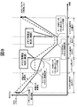
- FIG. 8 is an explanatory diagram showing a state of balancing control when the battery state changes in FIG. 7.
- the present invention is not limited to a hybrid vehicle (HEV) and an electric vehicle.
- the present invention can also be applied to an electric storage device control circuit of an electric storage device that constitutes a power source of an industrial vehicle such as a passenger car such as (EV) or a hybrid railway vehicle.
- the assembled battery is the storage unit
- the single cell is the storage unit
- the single battery group is the storage unit group
- the single battery control unit is the storage unit control unit
- the assembled battery control unit is the storage unit control unit.
- the cell control means and the assembled battery control means are realized as an integrated circuit on a circuit board. A combination of the cell control means and the assembled battery control means corresponds to the control means.
- FIG. 1 shows a configuration example of a PHEV power storage device according to an embodiment of the present invention.
- the power storage device 100 includes an assembled battery 110 composed of a plurality of single cells 111, a single cell management unit 120 that monitors the state of the single cell 111, a current detection unit 130 that detects a current flowing through the power storage device 100, and an assembled battery 110.
- a voltage detection unit 140 that detects the total voltage and an assembled battery control unit 150 that controls the assembled battery 110 are provided.
- the assembled battery control unit 150 includes the battery voltage and temperature of the unit cell 111 transmitted from the unit cell management unit 120, the current value flowing through the power storage device 100 transmitted from the current detection unit 130, and the group transmitted from the voltage detection unit 140.
- the total voltage value of the battery 110 is input, and the state of the assembled battery 110 is detected based on the input information. Further, the result of the processing performed by the assembled battery control unit 150 is transmitted to the single cell management unit 120 and the vehicle control unit 200.
- the vehicle control unit 200 controls the inverter 400 connected to the power storage device 100 via the relays 300 and 310 and the charger 420 connected via the relays 320 and 330 based on the information of the assembled battery control unit 150. I do. While the vehicle is traveling, power storage device 100 is connected to inverter 400 and drives motor generator 410 based on the energy stored in battery pack 110. At the time of charging, the power storage device 100 is connected to the charger 420 and is charged by power supply from a household power supply or a desk lamp.
- the assembled battery 110 is configured by electrically connecting a plurality of unit cells 111 (lithium ion batteries) capable of storing and releasing electrical energy (charging and discharging DC power) in series.
- unit cells 111 lithium ion batteries
- One unit cell 111 has an output voltage of 3.0 to 4.2 V (average output voltage: 3.6 V), and the open circuit voltage (OCV) of the unit cell 111 and the SOC are shown in FIG.
- OCV open circuit voltage
- the unit cells 111 constituting the assembled battery 110 are grouped into a predetermined number of units when managing and controlling the state.
- the grouped unit cells 111 are electrically connected in series to form unit cell groups 112a and 112b.
- the predetermined number of units may be divided into equal divisions such as 1, 4, 6, etc., or may be combined into divisions such as combining 4 and 6 units. .
- the high-potential side cell group 112a and the low-potential side cell group 112b are electrically connected in series via a maintenance / inspection service disconnector 180 in which a switch and a fuse are connected in series.
- the unit cell management means 120 for monitoring the state of the unit cells 111 constituting the assembled battery 110 includes a plurality of unit cell control units 121a and 121b, and the unit cell groups 112a and 112b grouped as described above.
- One single cell control means 121a, 121b is assigned to each.
- the unit cell control units 121a and 121b operate by receiving power from the allocated unit cell groups 112a and 112b, and monitor and control the states of the unit cells 111 constituting the unit cell groups 112a and 112b.
- the assembled battery 110 includes a total of eight unit cells 111, and the four unit cells 111 are electrically connected in series to form two unit cell groups 112a and 112b.
- the single battery groups are electrically connected in series via the service disconnector 180.
- unit cell control units 121a and 121b for monitoring the state of the unit cell 111 are installed in the unit cell groups 112a and 112b, respectively.
- the battery pack control means 150 includes a battery voltage and temperature measurement value output from the battery management means 120, a diagnosis result indicating whether the battery 111 is overcharged or overdischarged, and battery management.
- An abnormality signal output when a communication error or the like occurs in the means 120, a current value from the current detection means 130, a total voltage value of the assembled battery 110 output from the voltage detection means 140, and a host control device A plurality of signals including a signal output from a certain vehicle control means 200 are input.
- the SOC calculation of the unit cell 111 and the discharge termination condition described later are determined. Calculations for performing the balancing control included, calculations for controlling the charge / discharge amount, and the like are executed. And the calculation result and the instruction
- the assembled battery control unit 150 and the single cell management unit 120 perform signal transmission / reception by the signal communication unit 160 via an insulating element 170 such as a photocoupler.
- the reason why the insulating element 170 is provided is that the assembled battery control unit 150 and the unit cell management unit 120 have different operating power sources. That is, the unit cell management unit 120 operates by receiving power from the assembled battery 110, whereas the assembled battery control unit 150 uses a battery for on-vehicle auxiliary equipment (for example, a 14V system battery) as a power source.
- the insulating element 170 may be mounted on a circuit board constituting the unit cell management means 120 or may be mounted on a circuit board constituting the assembled battery control means 150. Of course, the unit cell management means 120 and the assembled battery control means 150 may be mounted on one circuit board. Note that the insulating element 170 may be omitted depending on the system configuration.
- the unit cell control units 121a and 121b are connected in series according to the order of potential of the unit cell groups 112a and 112b monitored by each unit.
- the signal transmitted by the assembled battery control means 150 is input to the single battery control means 121a by the signal communication means 160 via the insulating element 170.
- the signal communication means 160 connects between the output of the single battery control means 121a and the input of the single battery control means 121b to transmit signals.
- the cell control unit 121a and the cell control unit 121b are not provided with the insulating element 170, but may be provided with the insulating element 170.
- the output of the single battery control means 121b is transmitted by the signal communication means 160 via the insulating element 170 and the input of the assembled battery control means 150.
- the assembled battery control means 150, the single battery control means 121a, and the single battery control means 121b are connected in a loop by the signal communication means 160.
- This loop connection may be referred to as a daisy chain connection, a daisy chain connection, or a random connection.
- an example in which the unit cell control unit 121a and the unit cell control unit 121b are connected in a loop shape is shown.
- the unit cell control unit 150a and the unit cell control unit 121a are not necessarily in a loop shape. Any form may be used as long as the cell control means 121b is connected.
- FIG. 2 shows a circuit configuration of the cell control means 121a and 121b in the present embodiment.
- the cell control means 121a and 121b are a balancing circuit composed of a bypass resistor 122 and a bypass switch 123, a BSW drive circuit 125 for driving the bypass switch 123, and a voltage detection circuit for measuring the battery voltage of the cell 111 to be managed.
- a signal input / output circuit 129 that transmits and receives signals to and from the adjacent cell control means 121 is included.
- the storage device 127 such as an EEPROM stores the capacity of each unit cell measured in advance, information for balancing calculated by the assembled battery control means 150, and the like. Although details will be described later, the discharge time through the bypass resistor 122 of each unit cell required to reach the target SOC value is stored.
- the storage device 127 stores the state at the time of balancing interruption, for example, the elapsed time from the start of balancing (discharge time), the remaining time until the balancing is completed, the remaining balancing capacity, and each cell. Information on whether or not balancing has been completed, battery temperature at the start of balancing, and the like are written.
- storage device 127 in the cell control means 121a, 121b was shown here, the structure which memorize
- the control circuit 128 receives the voltage acquisition command and information related to balancing control transmitted from the assembled battery control means 150 via the signal input / output circuit 129, and the battery voltage detected by the voltage detection circuit 124 and information based thereon. Is output to the signal input / output circuit 129. Then, the control circuit 128 controls the BSW drive circuit 125 based on the detected battery voltage and information stored in the storage device 127.
- the discharge means is means for discharging the single cells 111 having a high SOC among the single cells 111 constituting the single cell group 112 using a balancing circuit including the bypass resistor 122 and the bypass switch 123. That is, by turning on the bypass switch 123 connected in parallel to the unit cell 111 to be discharged and using the bypass resistor 122, the unit cell 111 is forcibly discharged, and the target SOC (target SOC) To lower.
- the target SOC is a unit cell 111 constituting the unit cell group 112 when any one of the plurality of unit cells 111 constituting the assembled battery 110 is overcharged.
- This SOC is a predetermined SOC that is set to eliminate this variation when the SOC exceeds the allowable limit, and will be described in detail later.
- the discharge termination conditions described in the present embodiment are not limited to the following.
- the discharge end condition is determined based on the result of calculating the time required for discharging the unit cell 111.
- the time required to secure a predetermined discharge amount is calculated, and the discharge is terminated when the calculated time has elapsed. For this reason, in order to determine whether or not the calculated time has elapsed, the unit control means 121 is provided with a time measuring means such as a timer.
- the SOC is estimated based on the correlation between the SOC and the OCV from the OCV measurement results of all the unit cells 111 in the assembled battery no-load state, and the difference ⁇ SOC between the SOC of each unit cell 111 and the target SOC is expressed by the following equation: Obtain according to (1).
- Qmax is the full charge capacity [Ah] of the unit cell 111
- I B is the bypass current [A] flowing through the bypass resistor
- X represents the number of the unit cells 111 constituting the cell group.
- the adjustment time t is a discharge end condition for each unit cell. Based on the result of the expression (2), the unit cell 111 to be discharged is discharged, and when the time necessary to secure a predetermined discharge amount has elapsed, the discharge is terminated. In addition, instead of the adjustment time t, the balancing capacity ⁇ SOC ⁇ Qmax [Ah] of each unit cell 111 is obtained, and the discharge amount [Ah] is subtracted for each unit time therefrom, so that the balancing capacity is 0 [Ah] or less. It is good also as discharge end conditions.
- the discharging means uses a balancing circuit so that the battery voltage of the single cells 111 constituting the single cell group 112 matches the target value set for each single cell group 112.
- the high unit cell 111 is discharged.
- the target SOC of the cell group 112a is A
- the target SOC of the cell group 112b is B. Therefore, as shown in FIG. 4, the SOC of the single cells 111 constituting the single cell group 112 is decreased, and the SOC of all the single cells 111 constituting the single cell group 112 is the target. Discharge is terminated when the value matches.
- B the SOCs of all the cells 111 constituting the assembled battery 110 are calculated. B can be matched.
- FIG. 5 is an operation flow diagram of the assembled battery control means 150 while the vehicle is running or charging.
- step 11 a voltage (OCV) when all the cells 111 are not loaded or when the current is weak and can be regarded as no-load is acquired. OCV is converted into SOC using the relationship of FIG. Next, it progresses to step 12, and it is determined whether there exists variation in SOC of the cell 111 which comprises the cell group 112, and target SOC. If it is determined that there is variation, the process proceeds to step 13.
- step 13 the discharge end condition of the discharge means using the balancing circuit composed of the bypass resistor 122 and the bypass switch 123 is determined, and in step 14, the discharge end condition is transmitted to the single cell control means 121.
- FIG. 6 is a flowchart for explaining the operation of the unit cell control means 121 while the vehicle is running or charging.
- the cell control unit 121 receives the discharge end condition transmitted from the assembled battery control unit 150 and stores the received discharge end condition in the storage device 127.
- the discharge is not necessarily continuous, and may be intermittently performed using a pulse signal or duty control.
- the adjustment time t or the adjustment discharge amount ⁇ SOC ⁇ Qmax is determined by integrating only the discharge time and the discharge amount.
- step 23 it is determined whether or not the discharge of all the cells constituting the cell group 112 has been completed. If it is determined that the process has been completed, the cell control unit 121 ends the process. If it is determined in step 23 that the discharge of all the unit cells 111 has not ended, the process proceeds to step 24 to determine whether there is a unit cell 111 that satisfies the discharge end condition. If there is a unit cell 111 that has been discharged, the process proceeds to step 25, and the bypass switch 123 is turned off in order from the unit cell 111 that has been discharged. Then, it returns to step 23 and continues a process until discharge of all the cell 111 which comprises the cell group 112 is complete
- balancing control is performed in order to prevent an increase in capacity variation due to deterioration in a high SOC region. For example, in the high SOC region, on the basis of the unit cell having the lowest SOC value, a unit cell having an SOC higher by 0.5% or more than the SOC of the unit cell is selected as the balancing target unit cell.
- the amount of discharge and the discharge time required for matching the SOC of the balancing target cell to the lowest SOC are calculated by the above formulas (1) and (2), and only the discharge time determined by the calculation corresponds.
- the bypass switch 123 associated with the battery 111 is turned on and discharged via the bypass resistor 122. In this way, the variation in the cell SOC after balancing is suppressed to 0.5%. If the vehicle is keyed off (main switch off) before the balancing is completed, the balancing will be interrupted. At that time, the intermediate information at the time of balancing interruption, that is, the elapsed time from the start of balancing, or the remaining of each cell The discharge time, remaining capacity, etc.
- the balancing information stored at the time of the previous interruption is read from the storage device 127, and balancing is resumed based on the information.
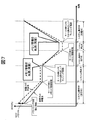
- FIG. 7 is an explanatory diagram showing a state of balancing control for resuming balancing using information at the time of balancing when balancing is interrupted.
- the horizontal axis is time, and the vertical axis is SOC.
- the SOC change of the large capacity unit cell based on the individual difference is shown by a solid line, and the SOC change of the small capacity unit cell is shown by a broken line.
- the vehicle is traveling in the section (T1, T2) and the section (T3, T4), and the assembled battery control means 150 (described as system in the figure) is operating. Further, it is assumed that the section (T5, T6) is being charged and the assembled battery control means 150 is operating.
- the assembled battery control means 150 is stopped in the sections (T2, T3) and sections (T4, T5) between them. It is assumed that the initial state at time T1 is a state where charging is finished. The balancing control is executed at a time when the assembled battery control means 150 is operating.
- the single cell having a smaller capacity indicated by the broken line is a solid line.
- the SOC is higher than that of the large-capacity unit cell shown, and the SOC varies as indicated by arrows. It is not preferable to leave the variation in a region where the SOC is high in this way, because the capacity variation increases due to deterioration of the unit cell. Therefore, when the SOC is high, for example, when the average SOC of the plurality of single cells 111 constituting the single cell group 112 is 75% or more, balancing is started. Assume that balancing is newly started at time T1.
- the assembled battery control means 150 interrupts the balancing operation, stores the balancing information at that time in the storage device 127, and then stops the operation.
- the information stored in the storage device 127 is, for example, an elapsed time (discharge time) from the start of balancing, or a remaining adjustment time obtained by subtracting the elapsed time from the discharge time required for SOC adjustment calculated for each cell. .
- the assembled battery control means 150 reads from the storage device 127 halfway information at the time of balancing interruption, and resumes balancing using the information.
- the assembled battery control means 150 stores in the storage device 127 balancing information at the time of interruption, that is, the elapsed time from the start of balancing, or the remaining time for each cell. Then stop the operation.
- the single battery with a small capacity indicated by a broken line has a faster SOC decreasing rate than the single battery with a large capacity indicated by a solid line. The relationship is reversed from that at time T1.
- the power storage device 100 is connected to the charger 420 at time T5 and the assembled battery control unit 150 resumes operation, the balancing intermediate information interrupted at time T4 is read from the storage device 127 again.
- Fig. 7 shows an ideal state.
- the variation in SOC may be deteriorated due to a change in the battery state or the like.
- the balancing information does not match the actual battery state, which causes a deterioration in SOC variation.
- FIG. 8 it is assumed that balancing is newly started to eliminate the SOC variation of the arrows that existed at time T1.
- intermediate information at the time of balancing interruption is stored in the storage device 127, and when the keys are turned on at times T3, T5, etc.
- the method of continuing the balancing by taking over the intermediate information at the time of balancing interruption is based on the premise that the SOC of each unit cell does not change between the balancing interruption and the restart.
- the battery state has changed for some reason while the assembled battery control means 150 is stopped from time T2 to time T3, when the SOC of the cell when the balancing is resumed at time T3, the balancing is interrupted at time T2. It will be different from the SOC. Therefore, as shown in the state at time T5, it is impossible to eliminate the SOC variation between the single cells in the high SOC state.
- any information of the old state information of the unit cell by balancing at the time of the previous battery activation stored in the storage device 127 and the new state information of the unit cell obtained by the current battery activation is used.
- the assembled battery control means 150 is provided with a determination unit that determines whether or not Then, when starting balancing in the current battery activation, the determination unit determines whether the balancing is performed based on the old state information or the new state information. When the battery is started this time, the assembled battery control unit 150 reacquires the current SOC of each unit cell 111 from the unit cell control unit 121, and based on the re-acquired SOC, each unit cell 111 necessary for SOC adjustment.
- the discharge time through the bypass resistor 122 is calculated.
- the determination unit compares the stored determination condition with a predetermined amount more than a predetermined amount from the previous balancing interruption, the determination unit calculates the discharge end condition calculated from the current SOC.
- the information is overwritten on the storage device 127. Otherwise, balancing is resumed using the halfway information at the time of balancing interruption stored in the storage device 127. In this way, the battery pack control means 150 is stopped by selecting any one of the current state information of each unit cell 111 and the old state information of each unit cell 111 at the time of the previous balancing interruption, and performing the balancing control. Even if there is a change in the battery state or the like, it is possible to satisfactorily equalize the SOC.
- FIG. 9 shows which one of the old state information of the unit cell 111 by balancing at the time of the previous battery activation stored in the storage device 127 and the new state information of the unit cell 111 obtained at the time of the current battery activation is used. It is explanatory drawing which shows the example of balancing control at the time of determining.
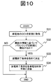
- FIG. 10 is a flowchart illustrating an example of processing executed before starting balancing control when the battery is activated.
- Balancing is newly started at time T1, and when the key is turned off at time T2, the assembled battery control unit 150 interrupts the balancing operation, stores the information during the balancing in the storage device 127, and then stops the operation. Until this is done, the process is the same as in FIG. Next, when the vehicle is keyed on at time T3 and the assembled battery control means 150 operates, the assembled battery control means 150 first executes the processing shown in FIG. That is, in step 31, the OCV of the unit cell 111 is acquired, and then the SOC is obtained using the relationship shown in FIG. Next, proceeding to step 32, it is determined whether or not balancing control should be newly started based on the latest SOC information acquired this time, or whether or not suspended balancing should be resumed using the halfway information stored in the storage device 127. I do.
- the balancing control is newly started based on the newly acquired SOC of the unit cell 111.
- the maximum SOC value may be determined in consideration of the SOC region in which the deterioration of the battery is promoted and the SOC region to which the user charges with PHEV or EV, but may be set to 70% or more, for example. .
- is equal to or greater than a predetermined value may be set using the SOC-OCV characteristic of FIG.
- the balancing capacity is a product ⁇ SOC ⁇ Qmax of the difference ⁇ SOC between the SOC of the unit cell and the target SOC and the full charge capacity Qmax of the unit cell.
- balancing is continued using information at the time of interruption, environmental changes, changes in battery characteristics, and errors in balancing accuracy increase during that time, and unevenness is not performed correctly and dispersion increases. This is because there is a risk of it. If the balancing process is nearing completion based on this criterion, it is possible to prevent the deterioration of the balancing accuracy and increase the variation by starting a new balancing process.
- How much time (days) should elapse after the last balancing start depends on how long it takes to complete the balancing of all balancing capacity, how often the user uses the vehicle, and the self-discharge characteristics of the battery It may be determined in consideration of variations in dark current and variations in dark current of the circuit to which each unit cell is connected. For example, when 30 days have passed since the start of the previous balancing operation, it was acquired in step 31. A new balancing may be started based on the SOC.
- the predetermined time may be determined in consideration of the polarization characteristics of the battery and its variation, for example, several minutes to several hours. This is because when the standing time is short, the state of the battery is not stable due to the influence of polarization or the like. This is because if balancing is newly started at this time, inaccurate battery variations may be detected. According to this standard, it is possible to prevent the start of balancing based on the SOC obtained when the battery state is not stable, and it is possible to prevent deterioration in balancing accuracy and increase in variation.
- the balancing is not newly started, and the intermediate information stored in the storage device 127 is used. To resume balancing.
- step 32 determines whether balancing is newly started based on the information newly acquired in step 31. If the determination in step 32 is NO, that is, when balancing is newly started based on the information newly acquired in step 31, the process proceeds to step 33, and the newly obtained SOC is used. Then, the discharge end condition is calculated according to the above formulas (1) and (2). In step 34, the calculated discharge end condition is transmitted to each unit cell control means 121.
- the unit cell control means 121 receives the transmitted discharge end condition in step 21 according to the procedure shown in FIG. Thereafter, as described above, the bypass switch 123 is controlled to open and close until each cell 111 satisfies the discharge termination condition, and the discharge through the bypass resistor 122 is continued.
- the continuous restart balancing by selecting one of the new / old battery status information and performing the balancing, the variation due to the battery status change, the bypass resistance error, etc. is deteriorated. Can be suppressed. Further, when the battery state becomes better (high SOC, etc.), the capacity adjustment condition can be newly acquired, and good balancing can be performed.
- each of the above-described configurations, functions, processing units, processing means, and the like may be realized by hardware by designing a part or all of them with, for example, an integrated circuit.
- Each of the above-described configurations, functions, and the like may be realized by software by interpreting and executing a program that realizes each function by the processor.
- Information such as programs, tables, and files for realizing each function can be stored in a recording device such as a memory, a hard disk, or an SSD (Solid State Drive), or a recording medium such as an IC card, an SD card, or a DVD.
Landscapes
- Engineering & Computer Science (AREA)
- Power Engineering (AREA)
- Manufacturing & Machinery (AREA)
- Chemical & Material Sciences (AREA)
- Chemical Kinetics & Catalysis (AREA)
- Electrochemistry (AREA)
- General Chemical & Material Sciences (AREA)
- Life Sciences & Earth Sciences (AREA)
- Sustainable Development (AREA)
- Sustainable Energy (AREA)
- Transportation (AREA)
- Mechanical Engineering (AREA)
- Charge And Discharge Circuits For Batteries Or The Like (AREA)
- Secondary Cells (AREA)
Abstract
Dans la présente invention, l'équilibrage se fait bien même si la commande de l'équilibrage est suspendue. La commande de l'équilibrage est effectuée en choisissant, en fonction des conditions, d'utiliser des informations sur les éléments de l'accumulateur obtenues de l'équilibrage précédent (informations d'état antérieur), qui sont stockées dans un dispositif de stockage, ou des informations sur les éléments de l'accumulateur qui ont été obtenues lors du démarrage courant (informations sur l'état nouveau).
Priority Applications (5)
| Application Number | Priority Date | Filing Date | Title |
|---|---|---|---|
| CN201180071067.9A CN103548233B (zh) | 2011-05-23 | 2011-05-23 | 蓄电器控制电路 |
| PCT/JP2011/061767 WO2012160638A1 (fr) | 2011-05-23 | 2011-05-23 | Circuit de commande d'unité de stockage d'électricité |
| JP2013516096A JP5610652B2 (ja) | 2011-05-23 | 2011-05-23 | 蓄電器制御回路 |
| US14/119,388 US9252602B2 (en) | 2011-05-23 | 2011-05-23 | Electric storage cell control circuit |
| EP11866313.7A EP2717421B1 (fr) | 2011-05-23 | 2011-05-23 | Circuit de commande d'unité de stockage d'électricité |
Applications Claiming Priority (1)
| Application Number | Priority Date | Filing Date | Title |
|---|---|---|---|
| PCT/JP2011/061767 WO2012160638A1 (fr) | 2011-05-23 | 2011-05-23 | Circuit de commande d'unité de stockage d'électricité |
Publications (1)
| Publication Number | Publication Date |
|---|---|
| WO2012160638A1 true WO2012160638A1 (fr) | 2012-11-29 |
Family
ID=47216741
Family Applications (1)
| Application Number | Title | Priority Date | Filing Date |
|---|---|---|---|
| PCT/JP2011/061767 Ceased WO2012160638A1 (fr) | 2011-05-23 | 2011-05-23 | Circuit de commande d'unité de stockage d'électricité |
Country Status (5)
| Country | Link |
|---|---|
| US (1) | US9252602B2 (fr) |
| EP (1) | EP2717421B1 (fr) |
| JP (1) | JP5610652B2 (fr) |
| CN (1) | CN103548233B (fr) |
| WO (1) | WO2012160638A1 (fr) |
Cited By (7)
| Publication number | Priority date | Publication date | Assignee | Title |
|---|---|---|---|---|
| JP2015220813A (ja) * | 2014-05-15 | 2015-12-07 | 株式会社ケーヒン | 電圧検出装置 |
| JP2016129478A (ja) * | 2014-12-25 | 2016-07-14 | 寧徳時代新能源科技股▲分▼有限公司 | リン酸鉄リチウム電池パックの受動的等化方法及びシステム |
| JP2016144398A (ja) * | 2015-02-05 | 2016-08-08 | 青海時代新能源科技有限公司 | リン酸鉄リチウム電池パックの能動的等化方法及びシステム |
| JP2018523965A (ja) * | 2015-07-10 | 2018-08-23 | ロエラ ヘマント カラムチャンドROHERA, Hemant Karamchand | ハイブリッドパワーパック |
| JP2023030692A (ja) * | 2021-08-23 | 2023-03-08 | 本田技研工業株式会社 | セル均等化システム |
| WO2023054606A1 (fr) * | 2021-09-30 | 2023-04-06 | ミネベアミツミ株式会社 | Dispositif d'alimentation électrique et son procédé de commande |
| JP2023516649A (ja) * | 2020-10-29 | 2023-04-20 | エルジー エナジー ソリューション リミテッド | バッテリー管理装置及び方法、バッテリー管理システム |
Families Citing this family (25)
| Publication number | Priority date | Publication date | Assignee | Title |
|---|---|---|---|---|
| DE112012001144B4 (de) | 2011-03-07 | 2025-10-02 | A123 Systems, LLC | Verfahren zum opportunistischen Ausgleichen von Ladung zwischen Batteriezellen |
| JP5502918B2 (ja) * | 2011-10-13 | 2014-05-28 | 株式会社日本自動車部品総合研究所 | 組電池の充放電装置 |
| KR101877564B1 (ko) * | 2011-11-30 | 2018-07-12 | 삼성에스디아이 주식회사 | 배터리 팩 |
| US9318910B2 (en) * | 2012-09-06 | 2016-04-19 | Samsung Sdi Co., Ltd. | Cell balancing circuit and cell balancing method using the same |
| US9236749B2 (en) * | 2013-04-08 | 2016-01-12 | GM Global Technology Operations LLC | Vehicle battery system balancing systems and methods |
| JP6200286B2 (ja) * | 2013-11-12 | 2017-09-20 | 矢崎総業株式会社 | 電源制御システム |
| DE102014205942A1 (de) * | 2014-03-31 | 2015-10-01 | Robert Bosch Gmbh | Verfahren zum Batteriemanagement einer Batterie mit einem Ladezustandsausgleichssystem und Batteriemanagementsystem |
| KR101704282B1 (ko) * | 2015-11-09 | 2017-02-07 | 현대자동차주식회사 | 셀밸런싱 고장이 제어오류인지 회로고장인지 진단하는 방법 |
| JP6361643B2 (ja) * | 2015-12-15 | 2018-07-25 | 横河電機株式会社 | 蓄電サービスシステム |
| ES3036519T3 (en) * | 2015-12-24 | 2025-09-19 | Vito Nv | Method, system and device for balancing individual electric energy storage cells |
| JP6679342B2 (ja) * | 2016-02-24 | 2020-04-15 | Ntn株式会社 | 二次電池の劣化判定装置 |
| KR101667913B1 (ko) * | 2016-03-25 | 2016-10-20 | (주)아이비티 | 충전특성곡선을 이용한 배터리 팩 균등 충전 장치 및 방법 |
| DE102016208420B4 (de) * | 2016-05-17 | 2025-12-24 | Fraunhofer-Gesellschaft zur Förderung der angewandten Forschung e.V. | Anordnung mit multifunktionalem Anschluss für Energiespeicherzellen oder Energieverbraucher |
| JP6883396B2 (ja) * | 2016-08-25 | 2021-06-09 | 矢崎総業株式会社 | 急速充電装置 |
| WO2018062394A1 (fr) * | 2016-09-29 | 2018-04-05 | 株式会社Gsユアサ | Dispositif d'estimation d'état de charge (soc) d'élément de stockage d'énergie, dispositif de stockage d'énergie et procédé d'estimation de soc d'élément de stockage d'énergie |
| EP3323665B1 (fr) * | 2016-11-18 | 2019-07-10 | Fico Triad, S.A. | Système et procédé pour l'équilibrage d'un bloc-batterie |
| US10322688B2 (en) * | 2016-12-30 | 2019-06-18 | Textron Innovations Inc. | Controlling electrical access to a lithium battery on a utility vehicle |
| JP6794889B2 (ja) * | 2017-03-21 | 2020-12-02 | 株式会社デンソー | 電圧検出装置 |
| JP6928347B2 (ja) * | 2017-08-02 | 2021-09-01 | NExT−e Solutions株式会社 | 管理装置、蓄電装置、蓄電システム、及び、電気機器 |
| CN109435776B (zh) * | 2017-08-31 | 2021-02-23 | 比亚迪股份有限公司 | 电池信息采集器、电池均衡系统、车辆、方法及存储介质 |
| CN108128186B (zh) * | 2017-12-18 | 2023-11-24 | 江苏海宝电池科技有限公司 | 一种铅酸动力电池管理系统及其控制方法 |
| DE102018214567A1 (de) * | 2018-08-29 | 2020-03-05 | Robert Bosch Gmbh | Verfahren und Vorrichtung für ein bedarfsorientiertes Cell-Balancing von Zellen einer Batterie für ein elektrisch angetriebenes Fortbewegungsmittel |
| JP7184028B2 (ja) * | 2019-12-19 | 2022-12-06 | トヨタ自動車株式会社 | 電力制御システム、電動車両および電力制御方法 |
| US12449485B2 (en) | 2020-11-05 | 2025-10-21 | Lg Energy Solution, Ltd. | Battery management apparatus and method |
| CN115836456A (zh) * | 2021-03-10 | 2023-03-21 | 华为数字能源技术有限公司 | 分布式供电系统和控制方法 |
Citations (3)
| Publication number | Priority date | Publication date | Assignee | Title |
|---|---|---|---|---|
| JP2004031012A (ja) | 2002-06-24 | 2004-01-29 | Nissan Motor Co Ltd | 組電池の容量調整装置および方法 |
| JP2008193871A (ja) * | 2007-02-07 | 2008-08-21 | Denso Corp | 車両用電池管理装置 |
| JP2011019329A (ja) * | 2009-07-08 | 2011-01-27 | Toshiba Corp | 二次電池装置及び車両 |
Family Cites Families (10)
| Publication number | Priority date | Publication date | Assignee | Title |
|---|---|---|---|---|
| JP3161215B2 (ja) * | 1994-03-15 | 2001-04-25 | 日産自動車株式会社 | 2次電池の充放電制御装置 |
| US6064178A (en) * | 1998-05-07 | 2000-05-16 | Ford Motor Company | Battery charge balancing system having parallel switched energy storage elements |
| JP3890168B2 (ja) * | 1999-08-03 | 2007-03-07 | 株式会社東京アールアンドデー | 電動装置及びその電池ユニットの充放電方法 |
| TW492021B (en) * | 1999-11-05 | 2002-06-21 | Tokin Corp | Electrical energy storage provided with cell energy adjusting device and adjust method of cell energy |
| JP2006246646A (ja) * | 2005-03-04 | 2006-09-14 | Yazaki Corp | 均等化方法及びその装置 |
| CN2886896Y (zh) * | 2005-12-30 | 2007-04-04 | 北京格林动力电源技术有限公司 | 一种锂电池组充电放电均衡控制装置 |
| KR100766982B1 (ko) * | 2006-09-05 | 2007-10-15 | 삼성에스디아이 주식회사 | 배터리 관리 시스템 및 그의 구동 방법 |
| CN100459368C (zh) * | 2006-09-14 | 2009-02-04 | 郑州市联合能源电子有限公司 | 动力型电池组均衡放电控制方法及装置 |
| JP4767220B2 (ja) * | 2007-06-22 | 2011-09-07 | 三洋電機株式会社 | 充電状態均等化装置及びこれを具えた電動車輌 |
| US8598847B2 (en) * | 2010-12-07 | 2013-12-03 | Volkswagen Ag | Balancing voltage for a multi-cell battery system |
-
2011
- 2011-05-23 US US14/119,388 patent/US9252602B2/en active Active
- 2011-05-23 WO PCT/JP2011/061767 patent/WO2012160638A1/fr not_active Ceased
- 2011-05-23 CN CN201180071067.9A patent/CN103548233B/zh active Active
- 2011-05-23 JP JP2013516096A patent/JP5610652B2/ja active Active
- 2011-05-23 EP EP11866313.7A patent/EP2717421B1/fr active Active
Patent Citations (3)
| Publication number | Priority date | Publication date | Assignee | Title |
|---|---|---|---|---|
| JP2004031012A (ja) | 2002-06-24 | 2004-01-29 | Nissan Motor Co Ltd | 組電池の容量調整装置および方法 |
| JP2008193871A (ja) * | 2007-02-07 | 2008-08-21 | Denso Corp | 車両用電池管理装置 |
| JP2011019329A (ja) * | 2009-07-08 | 2011-01-27 | Toshiba Corp | 二次電池装置及び車両 |
Non-Patent Citations (1)
| Title |
|---|
| See also references of EP2717421A4 |
Cited By (14)
| Publication number | Priority date | Publication date | Assignee | Title |
|---|---|---|---|---|
| JP2015220813A (ja) * | 2014-05-15 | 2015-12-07 | 株式会社ケーヒン | 電圧検出装置 |
| JP2016129478A (ja) * | 2014-12-25 | 2016-07-14 | 寧徳時代新能源科技股▲分▼有限公司 | リン酸鉄リチウム電池パックの受動的等化方法及びシステム |
| US10291038B2 (en) | 2014-12-25 | 2019-05-14 | Contemporary Amperex Technology Co., Limited | Passive equalization method and system for lithium iron phosphate battery pack |
| JP2016144398A (ja) * | 2015-02-05 | 2016-08-08 | 青海時代新能源科技有限公司 | リン酸鉄リチウム電池パックの能動的等化方法及びシステム |
| US10027134B2 (en) | 2015-02-05 | 2018-07-17 | Qinghai Contemporary Amperex Technology Limited | Active equalization method and system of lithium iron phosphate battery pack |
| JP2018523965A (ja) * | 2015-07-10 | 2018-08-23 | ロエラ ヘマント カラムチャンドROHERA, Hemant Karamchand | ハイブリッドパワーパック |
| JP2023516649A (ja) * | 2020-10-29 | 2023-04-20 | エルジー エナジー ソリューション リミテッド | バッテリー管理装置及び方法、バッテリー管理システム |
| JP7472430B2 (ja) | 2020-10-29 | 2024-04-23 | エルジー エナジー ソリューション リミテッド | バッテリー管理装置及び方法、バッテリー管理システム |
| JP2023030692A (ja) * | 2021-08-23 | 2023-03-08 | 本田技研工業株式会社 | セル均等化システム |
| JP7346504B2 (ja) | 2021-08-23 | 2023-09-19 | 本田技研工業株式会社 | セル均等化システム |
| US12388271B2 (en) | 2021-08-23 | 2025-08-12 | Honda Motor Co., Ltd. | Cell equalization system |
| WO2023054606A1 (fr) * | 2021-09-30 | 2023-04-06 | ミネベアミツミ株式会社 | Dispositif d'alimentation électrique et son procédé de commande |
| JP2023051555A (ja) * | 2021-09-30 | 2023-04-11 | ミネベアミツミ株式会社 | 電源装置及び電源装置の制御方法 |
| JP7831924B2 (ja) | 2021-09-30 | 2026-03-17 | ミネベアミツミ株式会社 | 電源装置及び電源装置の制御方法 |
Also Published As
| Publication number | Publication date |
|---|---|
| CN103548233B (zh) | 2016-01-20 |
| US20140217982A1 (en) | 2014-08-07 |
| JP5610652B2 (ja) | 2014-10-22 |
| EP2717421A1 (fr) | 2014-04-09 |
| EP2717421A4 (fr) | 2015-08-12 |
| JPWO2012160638A1 (ja) | 2014-07-31 |
| CN103548233A (zh) | 2014-01-29 |
| US9252602B2 (en) | 2016-02-02 |
| EP2717421B1 (fr) | 2020-11-04 |
Similar Documents
| Publication | Publication Date | Title |
|---|---|---|
| JP5610652B2 (ja) | 蓄電器制御回路 | |
| JP5546370B2 (ja) | 蓄電器制御回路及び蓄電装置 | |
| JP5668136B2 (ja) | 蓄電装置 | |
| EP2400626B1 (fr) | Circuit de contrôle de batterie | |
| JP6084225B2 (ja) | 電池制御装置、二次電池システム | |
| CN106030326B (zh) | 二次电池系统 | |
| EP3032695B1 (fr) | Système de commande de batterie et système de commande de véhicule | |
| EP3032690B1 (fr) | Système de commande de batterie et système de commande de véhicule | |
| WO2014156265A1 (fr) | Dispositif de commande de batterie | |
| WO2013094057A1 (fr) | Dispositif de commande de batterie et système de batterie | |
| JP2012178953A (ja) | 組電池の状態検出方法および制御装置 | |
| WO2012140776A1 (fr) | Dispositif de commande de charge | |
| RU2627298C1 (ru) | Система управления аккумуляторной батареей и система управления транспортным средством | |
| CN104553844A (zh) | 车辆和用于控制车辆中的电池的方法 | |
| JP2019124612A (ja) | 二次電池システム | |
| CN113016117A (zh) | 单电池控制器、蓄电池控制器、电池管理系统和电池系统 | |
| CN105452890A (zh) | 用于诊断蓄电池的状态的方法 | |
| JP5851514B2 (ja) | 電池制御装置、二次電池システム |
Legal Events
| Date | Code | Title | Description |
|---|---|---|---|
| 121 | Ep: the epo has been informed by wipo that ep was designated in this application |
Ref document number: 11866313 Country of ref document: EP Kind code of ref document: A1 |
|
| ENP | Entry into the national phase |
Ref document number: 2013516096 Country of ref document: JP Kind code of ref document: A |
|
| NENP | Non-entry into the national phase |
Ref country code: DE |
|
| WWE | Wipo information: entry into national phase |
Ref document number: 14119388 Country of ref document: US |