WO2012160695A1 - Fiche d'alimentation électrique, et dispositif électronique le comportant - Google Patents
Fiche d'alimentation électrique, et dispositif électronique le comportant Download PDFInfo
- Publication number
- WO2012160695A1 WO2012160695A1 PCT/JP2011/062107 JP2011062107W WO2012160695A1 WO 2012160695 A1 WO2012160695 A1 WO 2012160695A1 JP 2011062107 W JP2011062107 W JP 2011062107W WO 2012160695 A1 WO2012160695 A1 WO 2012160695A1
- Authority
- WO
- WIPO (PCT)
- Prior art keywords
- electrode pair
- plug
- capacitor
- electronic device
- power
- Prior art date
- Legal status (The legal status is an assumption and is not a legal conclusion. Google has not performed a legal analysis and makes no representation as to the accuracy of the status listed.)
- Ceased
Links
Images

Classifications
-
- H—ELECTRICITY
- H01—ELECTRIC ELEMENTS
- H01R—ELECTRICALLY-CONDUCTIVE CONNECTIONS; STRUCTURAL ASSOCIATIONS OF A PLURALITY OF MUTUALLY-INSULATED ELECTRICAL CONNECTING ELEMENTS; COUPLING DEVICES; CURRENT COLLECTORS
- H01R13/00—Details of coupling devices of the kinds covered by groups H01R12/70 or H01R24/00 - H01R33/00
- H01R13/66—Structural association with built-in electrical component
- H01R13/70—Structural association with built-in electrical component with built-in switch
- H01R13/703—Structural association with built-in electrical component with built-in switch operated by engagement or disengagement of coupling parts, e.g. dual-continuity coupling part
- H01R13/7031—Shorting, shunting or bussing of different terminals interrupted or effected on engagement of coupling part, e.g. for ESD protection, line continuity
-
- H—ELECTRICITY
- H01—ELECTRIC ELEMENTS
- H01R—ELECTRICALLY-CONDUCTIVE CONNECTIONS; STRUCTURAL ASSOCIATIONS OF A PLURALITY OF MUTUALLY-INSULATED ELECTRICAL CONNECTING ELEMENTS; COUPLING DEVICES; CURRENT COLLECTORS
- H01R2103/00—Two poles
-
- H—ELECTRICITY
- H01—ELECTRIC ELEMENTS
- H01R—ELECTRICALLY-CONDUCTIVE CONNECTIONS; STRUCTURAL ASSOCIATIONS OF A PLURALITY OF MUTUALLY-INSULATED ELECTRICAL CONNECTING ELEMENTS; COUPLING DEVICES; CURRENT COLLECTORS
- H01R24/00—Two-part coupling devices, or either of their cooperating parts, characterised by their overall structure
- H01R24/28—Coupling parts carrying pins, blades or analogous contacts and secured only to wire or cable
Definitions
- the present invention relates to a power plug and an electronic device including the power plug, and more particularly to a power plug and an electronic device that suppresses power consumption of the electronic device and protects a user who touches an electrode of the power plug from an electric shock.
- the noise filter for suppressing includes a noise removing capacitor, and the capacitor is connected between each line of the electrode pair provided in the power plug. For this reason, when the power plug of the electronic device is unplugged from the outlet, there is a risk that a user who touches the electrode pair provided on the power plug may receive an electric shock due to the residual charge remaining in the capacitor.
- an electronic device In order to prevent a user from touching an electrode pair provided on a power plug and receiving an electric shock, an electronic device is generally provided with a discharge resistor for discharging the residual charge of the capacitor, and the discharge resistor is connected to the power plug.
- a capacitor is connected in parallel between each line of the provided electrode pair.
- an AC voltage is also supplied from the power plug to the discharge resistor when the power plug is inserted into an outlet, and the discharge A current flows through the resistor, and power is consumed by the discharge resistor. For this reason, standby power consumed during standby of the electronic device has been increased.
- demands for power saving of standby power of electronic devices have further increased, and the proportion of power consumed by discharge resistors in standby power has increased. For this reason, the importance of reducing the power consumed by the discharge resistor is increasing.
- Each of the above patent documents includes an inlet provided in the electronic device main body, a capacitor for noise removal, and a discharge resistor. When the power plug is inserted into the inlet, the capacitor and the discharge resistor are disconnected. A configuration for making a state is disclosed. This electronic device is operated by supplying power from an outlet to the inlet.
- Patent Documents 1 and 2 when the power plug is inserted into the inlet, the capacitor and the discharge resistor are disconnected even when the power plug is removed from the outlet, so the residual charge of the capacitor is No discharge resistance. For this reason, the user who touched the electrode pair of the power plug pulled out from the outlet connected to the capacitor may be electrocuted.
- Patent Document 3 discloses an electronic device main body provided with a power plug provided with a detection unit, a capacitor, and a switch. Is described. In the power supply device described in Patent Literature 3, when the detection unit detects that the power plug is disconnected from the outlet, the switch disconnects the line connected to the electrode of the power plug and the capacitor.
- Patent Document 4 discloses an AC provided with a discharge resistor and a switch connected in series to the discharge resistor. The plug is listed. The AC plug supplies power from the outlet to the electronic device body, and a capacitor provided in the electronic device body is connected between the lines of the electrode pairs of the AC plug.
- the switch is turned on when the AC plug is removed from the outlet. For this reason, the electrode pair of the AC plug and the discharge resistor are in a connected state, and the residual charge of the capacitor connected to one electrode of the electrode pair of the AC plug flows to the other electrode through the discharge resistor and is discharged. It is possible to avoid an electric shock from a user who touches the electrode pair of the AC plug.
- Patent Documents 1 and 2 disconnect the noise removing capacitor and the discharge resistor when the power plug is inserted into the inlet. Therefore, when the power plug is inserted into the inlet, there is a problem that the residual charge of the capacitor is not discharged to the discharge resistor when the power plug is removed from the outlet, and there is a possibility that the user may be electrocuted. There's a problem.
- the power supply device described in Patent Document 3 disconnects a switch provided in the main body of the electronic device when the detection unit provided in the power plug detects that the power plug is removed from the outlet.
- a control line for controlling the switch since the switch is provided in the electronic apparatus main body, a control line for controlling the switch must be provided between the switch and the detection unit provided in the power plug.
- the configuration becomes complicated.
- An object of the present invention includes a power plug and a power plug that can more reliably prevent a user touching an electrode of the power plug from receiving an electric shock with a simple configuration while suppressing power consumption of an electronic device. Is to provide electronic equipment.
- the power plug of the present invention is a power plug used in an electronic device having a capacitor for removing noise in the internal circuit, and an electrode pair for receiving an AC voltage supplied from the AC power source to the internal circuit, When the electrode pair is connected to the AC power supply, one of the electrode pair and one end of the capacitor are brought into conduction, and the other of the electrode pair and the other end of the capacitor are brought into conduction. And a switch circuit that disconnects each of the electrode pairs when the electrode pairs are separated from each other.
- An electronic apparatus includes an internal circuit that receives an AC voltage supplied from an AC power supply and executes a predetermined process, a capacitor for removing noise in the internal circuit, and an electrode pair for receiving the AC voltage And when the electrode pair is connected to the AC power source, one of the electrode pair and one end of the capacitor are brought into conduction, and the other of the electrode pair and the other end of the capacitor are brought into conduction, And a switch circuit that disconnects each of the electrode pairs when the electrode pairs are disconnected from an AC power source.
- the present invention it is possible to more reliably prevent a user who touches the electrode of the power plug from receiving an electric shock with a simple configuration while suppressing power consumption of the electronic device.
- FIG. 1 is a block diagram showing an electronic device in the present embodiment.
- the electronic device 1 receives an AC voltage supplied from an AC (Alternating Current) power supply and executes a predetermined function.
- the electronic device 1 is realized, for example, by a projector that receives an image signal, modulates light from a light source according to the image signal, and projects the image as an image.
- the electronic device 1 includes an AC plug 10, an electronic device main body 20, and an AC cord 30.
- the AC plug 10 includes an electrode pair 11, a switch circuit 12, and a housing 13.
- the electrode pair 11 includes an electrode 11a and an electrode 11b.
- the AC cord 30 includes power supply lines 30 a and 30 b that connect the AC plug 10 and the electronic device main body 20.
- the electronic device main body 20 includes an internal circuit 21 and a capacitor 22.
- the internal circuit 21 receives the AC voltage supplied from the AC power source via the AC cord 30 and executes a predetermined process.
- the internal circuit 21 is realized by an AC filter circuit, for example.
- the capacitor 22 is a capacitive element used for a noise filter for removing noise in the internal circuit 21.
- the capacitor 22 is provided between the lines of the electrode pair 11 so as not to leak noise generated in the internal circuit 21 to the outside, and further to prevent external noise from being input to the internal circuit 21, and is parallel to the internal circuit 21. Connected to.
- AC plug 10 can generally be called a power plug.
- the AC plug 10 is a plug connected to an AC power outlet.
- the AC plug 10 is connected to a two-core outlet.
- an AC plug connected to a three-core consensus having an FG (Frame Ground) terminal may be used.
- the electrode pair 11 is used for receiving an AC voltage supplied from the AC power source to the electronic device main body 20.
- a capacitor 22 is connected between the lines of the electrodes 11a and 11b.
- the switch circuit 12 is provided between the electrode pair 11 and the capacitor 22.
- the switch circuit 12 connects the electrode 11a and one power supply line 30a constituting the AC cord 30, and connects the electrode 11b and the power supply line 30b.
- the switch circuit 12 is turned on when the electrode pair 11 is connected to an AC power outlet, and is turned off when the electrode pair 11 is disconnected from the outlet.
- the switch circuit 12 connects the capacitor 22 in series between the electrode pair 11 in a state where the electrode pair 11 is connected to an AC power source. That is, the switch circuit 12 makes one electrode 11a of the electrode pair 11 and one end of the capacitor 22 conductive, and makes the other electrode 11b and the other end of the capacitor 22 conductive.
- the switch circuit 12 turns off the electrodes 11a and 11b. That is, the switch circuit 12 disconnects (opens) one electrode 11a and one end of the capacitor 22 in a state where the electrode pair 11 is not connected to the AC power source, and the other electrode 11b and the capacitor 22 Cut off the other end.
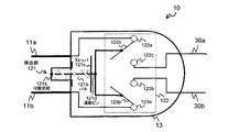
- FIG. 2 is a diagram illustrating the internal structure of the AC plug 10.
- FIG. 2 shows the connection state of the switch circuit when the AC plug 10 is not connected to the outlet.
- the switch circuit includes a detection unit 121 and a switch 122.
- the detection unit 121 is formed on the same surface as the surface of the housing 13 on which the electrodes 11a and 11b are arranged, and is provided between the electrode 11a and the electrode 11b.
- the detection unit 121 protrudes to the outside of the housing 13 when pulled out from the outlet of the AC power supply, and moves to the inside of the housing 13 when inserted into the outlet.
- the detection unit 121 includes a movable protrusion 121a, a spring 121b, a stopper 121c of the spring 121b, and an interlocking pin 121d.
- the switch 122 is a change-over switch that switches the connection state between the electrode pairs 11 a and 11 b and the capacitor 22 in conjunction with the detection unit 121.
- the switch 122 includes fulcrums 122a and 123a, operation pieces 122b and 123b, and contacts 122c and 123c. Each of the operation pieces 122b and 123b is connected to the interlocking pin 121d.
- the switch 122 is turned off. That is, in the switch 122, the fulcrum 122a and the contact 122c are in an open state (open state), and the fulcrum 123a and the contact 123c are in an open state.
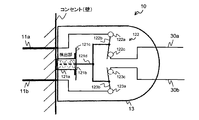
- FIG. 3 is a diagram illustrating a switch connection state when the AC plug 10 is connected to an outlet.
- the detecting unit 121 Since the AC plug 10 is inserted into the outlet, the detecting unit 121 is pushed by the outlet part of the outlet and moves inside the housing 13. Therefore, the movable protrusion 121a is pushed into the housing 13 and the interlocking pin 121d is moved to the inside of the housing 13.
- the operation pieces 122b and 123b coupled to the interlocking pin 121d are connected to the contacts 122c and 123c, respectively, and the switch 122 is turned on. That is, in the switch 122, the operation piece 122b and the contact 122c are in a conductive state, and the operation piece 123b and the contact 123c are in a conductive state.
- the AC voltage supplied from the AC power outlet is supplied to the internal circuit 21 shown in FIG. 1 via the power supply lines 30a and 30b.
- no discharge resistor for discharging the residual charge of the capacitor 22 is provided, no AC voltage is consumed by the discharge resistor. For this reason, the power consumed by the discharge resistor can be reduced.
- the AC plug 10 used in the electronic device 1 having the capacitor 22 for removing the noise of the internal circuit 21 is an electrode pair for receiving an AC voltage supplied from the AC power source to the internal circuit 21. 11.
- the switch circuit 12 brings one of the electrode pair 11 and one end of the capacitor 22 into a conductive state, and the other of the electrode pair 11 and the capacitor 22. Make the other end conductive.
- the switch circuit 12 places each of the electrode pair 11 in a disconnected state.
- the switch circuit 12 disconnects each of the electrode pair 11 connected to the capacitor 22. For this reason, even if the user touches the electrode pair 11, there is no electric shock. Therefore, the AC plug 10 can protect the user who touched the electrode pair 11 from an electric shock with a simple configuration without using a discharge resistor.
- the switch circuit 12 cuts both ends of the capacitor 22 when the electrode pair 11 is removed from the outlet. For this reason, the voltage between the electrodes 11a and 11b can be suppressed within an extremely short time compared to a switch that cuts only one end of the capacitor 22.
- an electronic device that discharges the residual charge of the capacitor 22 to the discharge resistor
- a current flows through the discharge resistor in a state where it is plugged into an outlet power is consumed by the discharge resistor, and the power consumption of the electronic device increases.
- the AC plug 10 since the AC plug 10 is not provided with a discharge resistor, power is not consumed by the discharge resistor when the electrode pair 11 is inserted into the outlet. For this reason, the AC plug 10 can reduce the power consumption of the electronic device 1 as compared with an electronic device using a discharge resistor.
- the magnitude of the discharge resistor is changed according to the capacitance of the capacitor 22 in order to reduce the voltage between the electrodes of the AC plug within the time specified by the safety standard of the AC plug. There is a need. For this reason, depending on the discharge resistance provided in the AC plug, it takes a long time for the residual charge of the capacitor 22 to be discharged after the AC plug is removed from the outlet. The risk of doing so may increase.
- the switch circuit 12 protrudes to the outside of the AC plug when the electrode pair 11 is removed from the outlet of the AC power supply, and moves to the inside of the AC plug 10 when the electrode pair 11 is inserted into the outlet.
- a detection unit 121 and a switch 122 that switches a connection state between the electrode pair 11 and the capacitor 22 in conjunction with the detection unit 121 are provided.
- the detection unit 121 protrudes outside the AC plug 10, and the switch 122 is in a disconnected state.
- the detection unit 121 moves to the inside of the AC plug 10, and the switch 122 becomes conductive in conjunction with the moved detection unit 121.
- the AC plug 10 can mechanically detect whether the AC voltage is supplied to the electrode pair 11 by providing the detection unit 121. For this reason, the AC plug 10 or the electronic device 1 can be realized with a simple configuration rather than using a detection circuit that detects whether or not an AC voltage is supplied from an AC power supply using an electronic circuit. Furthermore, since the detection unit 121 does not cause erroneous detection due to electronic noise or the like, the connection state of the switch 122 can be switched more accurately than the detection circuit.
- a main body switch for connecting the power supply line 30a connected to the power source 11a and the capacitor 22 to the electronic device main body 20 can be provided.
- a main body switch is provided in the electronic device main body 20
- a control line for controlling the main body switch is required between the AC plug and the electronic device main body 20, which complicates the configuration of the electronic device.
- noise may enter the control line and the main body switch may malfunction.
- the main body switch contacts the electrode pair 11 with a simple configuration as compared with the electronic device provided in the electronic device main body.
- the user can be protected from electric shock.
- the electronic device 1 since it is not necessary to provide a control line, noise does not enter the control line and the switch 122 does not malfunction. For this reason, it becomes possible to prevent more reliably that the user who contacted the electrode pair 11 compared with the electronic device with which a main body switch is provided in an electronic device main body receives an electric shock.
- the illustrated configuration is merely an example, and the present invention is not limited to the configuration.
Landscapes
- Details Of Connecting Devices For Male And Female Coupling (AREA)
Abstract
L'objet de la présente invention est de prévenir de manière plus fiable l'électrocution d'un utilisateur qui est entré en contact avec une paire d'électrodes d'une fiche d'alimentation électrique en réduisant la consommation d'énergie d'un dispositif électronique tout en utilisant une configuration simple. Une fiche pour CA, qui est utilisée dans un dispositif électronique qui a un condensateur permettant de retirer le bruit du circuit interne, comporte : une paire d'électrodes permettant de recevoir une tension alternative produite par une source de courant alternatif pour un circuit interne ; et un circuit de commutation qui, quand la paire d'électrodes est connectée à la source de courant alternatif, met une des électrodes de la paire d'électrodes et un bord du condensateur dans un état conducteur tout en mettant aussi l'autre électrode de la paire d'électrodes et l'autre bord du condensateur dans un état conducteur, et qui, quand la paire d'électrodes est séparée de la source de courant alternatif, met chacune des électrodes de la paire d'électrodes dans un état déconnecté.
Priority Applications (1)
| Application Number | Priority Date | Filing Date | Title |
|---|---|---|---|
| PCT/JP2011/062107 WO2012160695A1 (fr) | 2011-05-26 | 2011-05-26 | Fiche d'alimentation électrique, et dispositif électronique le comportant |
Applications Claiming Priority (1)
| Application Number | Priority Date | Filing Date | Title |
|---|---|---|---|
| PCT/JP2011/062107 WO2012160695A1 (fr) | 2011-05-26 | 2011-05-26 | Fiche d'alimentation électrique, et dispositif électronique le comportant |
Publications (1)
| Publication Number | Publication Date |
|---|---|
| WO2012160695A1 true WO2012160695A1 (fr) | 2012-11-29 |
Family
ID=47216797
Family Applications (1)
| Application Number | Title | Priority Date | Filing Date |
|---|---|---|---|
| PCT/JP2011/062107 Ceased WO2012160695A1 (fr) | 2011-05-26 | 2011-05-26 | Fiche d'alimentation électrique, et dispositif électronique le comportant |
Country Status (1)
| Country | Link |
|---|---|
| WO (1) | WO2012160695A1 (fr) |
Cited By (3)
| Publication number | Priority date | Publication date | Assignee | Title |
|---|---|---|---|---|
| WO2017067886A1 (fr) * | 2015-10-19 | 2017-04-27 | Bals Elektrotechnik Gmbh & Co. Kg | Prise femelle à moyen d'identification |
| DE102019205623A1 (de) * | 2019-04-17 | 2020-10-22 | BSH Hausgeräte GmbH | Netzfiltervorrichtung für ein Haushaltsgerät, Haushaltsgerät sowie Verfahren |
| KR20240003262A (ko) * | 2022-06-30 | 2024-01-08 | 김윤회 | 안전 플러그 |
Citations (1)
| Publication number | Priority date | Publication date | Assignee | Title |
|---|---|---|---|---|
| JP2005353306A (ja) * | 2004-06-08 | 2005-12-22 | Sony Corp | Acプラグ、および、それを備える電気機器 |
-
2011
- 2011-05-26 WO PCT/JP2011/062107 patent/WO2012160695A1/fr not_active Ceased
Patent Citations (1)
| Publication number | Priority date | Publication date | Assignee | Title |
|---|---|---|---|---|
| JP2005353306A (ja) * | 2004-06-08 | 2005-12-22 | Sony Corp | Acプラグ、および、それを備える電気機器 |
Cited By (4)
| Publication number | Priority date | Publication date | Assignee | Title |
|---|---|---|---|---|
| WO2017067886A1 (fr) * | 2015-10-19 | 2017-04-27 | Bals Elektrotechnik Gmbh & Co. Kg | Prise femelle à moyen d'identification |
| DE102019205623A1 (de) * | 2019-04-17 | 2020-10-22 | BSH Hausgeräte GmbH | Netzfiltervorrichtung für ein Haushaltsgerät, Haushaltsgerät sowie Verfahren |
| KR20240003262A (ko) * | 2022-06-30 | 2024-01-08 | 김윤회 | 안전 플러그 |
| KR102718989B1 (ko) * | 2022-06-30 | 2024-10-16 | 김윤회 | 안전 플러그 |
Similar Documents
| Publication | Publication Date | Title |
|---|---|---|
| JP5835152B2 (ja) | 車両用充電装置 | |
| TWI235516B (en) | Power supply unit for electronic devices | |
| KR101544424B1 (ko) | 향상된 기능을 갖는 액세서리 검지 회로 | |
| JP6181384B2 (ja) | 携帯端末 | |
| CN209282474U (zh) | Usb插座和usb充电系统 | |
| WO2012160695A1 (fr) | Fiche d'alimentation électrique, et dispositif électronique le comportant | |
| JP5982692B2 (ja) | 充電/放電管理装置およびモバイル端末 | |
| CN107017531A (zh) | 一种直流连接器、交直流输入设备和交直流输入系统 | |
| US8814600B2 (en) | Connection jack and electronic apparatus | |
| JP4977847B2 (ja) | 電源装置、及びコネクタ | |
| CN206517124U (zh) | 充电器 | |
| CN106356952A (zh) | 一种充电线缆、充电器及充电控制方法 | |
| CN103682856A (zh) | Io端口和具有io端口的电子装置 | |
| US20160118840A1 (en) | Battery pack and portable electronic apparatus | |
| CN104183434A (zh) | 一种具有反接线结构的漏电断路器 | |
| WO2020088388A1 (fr) | Circuit de commande de charge, circuit de charge et procédé de commande de charge | |
| CN110707782B (zh) | 充电控制电路、充电通信电路、电子设备及充电控制方法 | |
| CN102761114B (zh) | 浪涌电流抑制电路 | |
| CN205123559U (zh) | 通断控制电路 | |
| CN103108062B (zh) | 一种sim卡组件和手机 | |
| CN106299898B (zh) | 一种接口保护装置及保护方法 | |
| CN109417286B (zh) | 一种伺服驱动器的检测电路及伺服驱动器 | |
| KR101245684B1 (ko) | 릴레이와 이를 포함하는 전압 공급 제어 장치 | |
| CN102566725A (zh) | Cmos数据清除电路 | |
| CN202034322U (zh) | 一种万能式断路器 |
Legal Events
| Date | Code | Title | Description |
|---|---|---|---|
| 121 | Ep: the epo has been informed by wipo that ep was designated in this application |
Ref document number: 11866120 Country of ref document: EP Kind code of ref document: A1 |
|
| NENP | Non-entry into the national phase |
Ref country code: DE |
|
| NENP | Non-entry into the national phase |
Ref country code: JP |
|
| 122 | Ep: pct application non-entry in european phase |
Ref document number: 11866120 Country of ref document: EP Kind code of ref document: A1 |