WO2012160738A1 - 非水電解質二次電池用正極活物質、非水電解質二次電池、車両、および非水電解質二次電池用正極活物質の製造方法 - Google Patents
非水電解質二次電池用正極活物質、非水電解質二次電池、車両、および非水電解質二次電池用正極活物質の製造方法 Download PDFInfo
- Publication number
- WO2012160738A1 WO2012160738A1 PCT/JP2012/001841 JP2012001841W WO2012160738A1 WO 2012160738 A1 WO2012160738 A1 WO 2012160738A1 JP 2012001841 W JP2012001841 W JP 2012001841W WO 2012160738 A1 WO2012160738 A1 WO 2012160738A1
- Authority
- WO
- WIPO (PCT)
- Prior art keywords
- positive electrode
- active material
- electrode active
- secondary battery
- electrolyte secondary
- Prior art date
- Legal status (The legal status is an assumption and is not a legal conclusion. Google has not performed a legal analysis and makes no representation as to the accuracy of the status listed.)
- Ceased
Links
Images






Classifications
-
- H—ELECTRICITY
- H01—ELECTRIC ELEMENTS
- H01M—PROCESSES OR MEANS, e.g. BATTERIES, FOR THE DIRECT CONVERSION OF CHEMICAL ENERGY INTO ELECTRICAL ENERGY
- H01M4/00—Electrodes
- H01M4/02—Electrodes composed of, or comprising, active material
- H01M4/36—Selection of substances as active materials, active masses, active liquids
- H01M4/362—Composites
- H01M4/364—Composites as mixtures
-
- H—ELECTRICITY
- H01—ELECTRIC ELEMENTS
- H01M—PROCESSES OR MEANS, e.g. BATTERIES, FOR THE DIRECT CONVERSION OF CHEMICAL ENERGY INTO ELECTRICAL ENERGY
- H01M4/00—Electrodes
- H01M4/02—Electrodes composed of, or comprising, active material
- H01M4/04—Processes of manufacture in general
- H01M4/0471—Processes of manufacture in general involving thermal treatment, e.g. firing, sintering, backing particulate active material, thermal decomposition, pyrolysis
-
- H—ELECTRICITY
- H01—ELECTRIC ELEMENTS
- H01M—PROCESSES OR MEANS, e.g. BATTERIES, FOR THE DIRECT CONVERSION OF CHEMICAL ENERGY INTO ELECTRICAL ENERGY
- H01M4/00—Electrodes
- H01M4/02—Electrodes composed of, or comprising, active material
- H01M4/36—Selection of substances as active materials, active masses, active liquids
- H01M4/362—Composites
- H01M4/366—Composites as layered products
-
- H—ELECTRICITY
- H01—ELECTRIC ELEMENTS
- H01M—PROCESSES OR MEANS, e.g. BATTERIES, FOR THE DIRECT CONVERSION OF CHEMICAL ENERGY INTO ELECTRICAL ENERGY
- H01M4/00—Electrodes
- H01M4/02—Electrodes composed of, or comprising, active material
- H01M4/36—Selection of substances as active materials, active masses, active liquids
- H01M4/58—Selection of substances as active materials, active masses, active liquids of inorganic compounds other than oxides or hydroxides, e.g. sulfides, selenides, tellurides, halogenides or LiCoFy; of polyanionic structures, e.g. phosphates, silicates or borates
- H01M4/5825—Oxygenated metallic salts or polyanionic structures, e.g. borates, phosphates, silicates, olivines
-
- H—ELECTRICITY
- H01—ELECTRIC ELEMENTS
- H01M—PROCESSES OR MEANS, e.g. BATTERIES, FOR THE DIRECT CONVERSION OF CHEMICAL ENERGY INTO ELECTRICAL ENERGY
- H01M50/00—Constructional details or processes of manufacture of the non-active parts of electrochemical cells other than fuel cells, e.g. hybrid cells
- H01M50/10—Primary casings; Jackets or wrappings
- H01M50/147—Lids or covers
-
- H—ELECTRICITY
- H01—ELECTRIC ELEMENTS
- H01M—PROCESSES OR MEANS, e.g. BATTERIES, FOR THE DIRECT CONVERSION OF CHEMICAL ENERGY INTO ELECTRICAL ENERGY
- H01M4/00—Electrodes
- H01M4/02—Electrodes composed of, or comprising, active material
- H01M2004/021—Physical characteristics, e.g. porosity, surface area
-
- Y—GENERAL TAGGING OF NEW TECHNOLOGICAL DEVELOPMENTS; GENERAL TAGGING OF CROSS-SECTIONAL TECHNOLOGIES SPANNING OVER SEVERAL SECTIONS OF THE IPC; TECHNICAL SUBJECTS COVERED BY FORMER USPC CROSS-REFERENCE ART COLLECTIONS [XRACs] AND DIGESTS
- Y02—TECHNOLOGIES OR APPLICATIONS FOR MITIGATION OR ADAPTATION AGAINST CLIMATE CHANGE
- Y02E—REDUCTION OF GREENHOUSE GAS [GHG] EMISSIONS, RELATED TO ENERGY GENERATION, TRANSMISSION OR DISTRIBUTION
- Y02E60/00—Enabling technologies; Technologies with a potential or indirect contribution to GHG emissions mitigation
- Y02E60/10—Energy storage using batteries
Definitions
- the present invention relates to a positive electrode active material of a non-aqueous electrolyte secondary battery represented by a lithium ion secondary battery, a method for producing the same, a non-aqueous electrolyte secondary battery using the positive electrode active material, the non-aqueous electrolyte secondary battery It relates to the mounted vehicle.
- Lithium secondary batteries and lithium ion secondary batteries are known as a type of non-aqueous electrolyte secondary battery. These non-aqueous electrolyte secondary batteries are compact and have high energy density, and are widely used as power sources for portable electronic devices.
- lithium silicate compounds have attracted attention as positive electrode active materials. Lithium silicate compounds have low environmental impact because they are inexpensive and consist only of abundant metal resources, and theoretical charge and discharge capacity of lithium ion is higher than Li (NiCo) O 2 etc.
- it since it is a material that does not release oxygen at high temperatures, it is attracting attention as a material for the next generation lithium ion secondary battery positive electrode (see, for example, Patent Documents 1 to 5).
- the lithium silicate-based compound has the excellent properties as described above, the conductivity is low. Therefore, there has been a problem that the utilization factor of the active material of the non-aqueous electrolyte secondary battery using such a lithium silicate compound as a positive electrode material is low. It is thought that the capacity of the non-aqueous electrolyte secondary battery can be further improved by improving the conductivity of this positive electrode active material.
- a conductive aid such as carbon (C) (see, for example, Non-Patent Document 1).
- a conductive aid such as carbon (C)
- JP 2008-218303 A JP 2007-335325 A JP, 2001-266882, A JP 2008-293661A International Publication No. 2010/089931
- An object of the present invention is to provide a positive electrode active material for a non-aqueous electrolyte secondary battery which contains a lithium silicate-based compound and is excellent in conductivity, and a non-aqueous electrolyte secondary battery using the positive electrode active material.
- the positive electrode active material for a non-aqueous electrolyte secondary battery of the present invention which solves the above problems, comprises a lithium silicate compound containing lithium (Li), silicon (Si), oxygen (O) and a divalent transition metal element, and carbon (C) containing a carbon material, It is characterized by having two peaks in the particle size distribution by the laser diffraction scattering type particle size distribution measurement method.
- the non-aqueous electrolyte secondary battery of the present invention for solving the above problems is characterized in that the positive electrode active material of the present invention is contained in the positive electrode.
- a method for producing a positive electrode active material for a non-aqueous electrolyte secondary battery according to the present invention comprises a lithium silicate compound containing lithium (Li), silicon (Si), oxygen (O) and a divalent transition metal element. And a carbon material containing carbon (C) at a mixing speed of 450 to 16000 rpm for 1 minute to 10 hours. And heating and pressurizing the mixture after the mixing step at 500 to 750 ° C. and 1 to 500 MPa for 1 minute to 15 hours.
- the positive electrode active material for a non-aqueous electrolyte secondary battery of the present invention is excellent in conductivity.
- the charge and discharge capacity of the non-aqueous electrolyte secondary battery of the present invention is large.
- FIG. 1 is a schematic view showing a general discharge plasma sintering apparatus. It is a graph showing the particle size distribution of the positive electrode active material of Example (# 1) by a laser diffraction scattering type particle size distribution measuring method. It is a graph showing the particle size distribution of the positive electrode active material of Example (# 2) by a laser diffraction scattering type particle size distribution measuring method. It is a graph showing the particle size distribution of the positive electrode active material of the Example (# 3) by a laser diffraction scattering type particle size distribution measuring method. It is a graph showing the particle size distribution of the positive electrode active material of the comparative example (# 1) by a laser diffraction scattering type particle size distribution measuring method.
- the amount of carbon in order to improve the conductivity, it is considered preferable to increase the amount of carbon relative to the lithium silicate compound, but increasing the amount of carbon reduces the bulk density of the positive electrode active material (the positive electrode active material becomes bulky).
- the bulk density of the positive electrode active material is small, it becomes difficult to form an electrode, and the amount of the positive electrode active material in the positive electrode mixture decreases, which causes a problem of decreasing the charge / discharge capacity of the non-aqueous electrolyte secondary battery.
- the inventors of the present invention found that a mixture having a large bulk density and an excellent conductivity can be obtained by heating and pressurizing after sufficiently mixing the lithium silicate compound and the carbon material. And it discovered that the charge / discharge capacity of a nonaqueous electrolyte secondary battery could be improved by using this composite as a positive electrode active material. Furthermore, it has been found that various characteristics of the vehicle can be improved by mounting the non-aqueous electrolyte secondary battery with improved charge and discharge capacity.
- the step of mixing the lithium silicate compound and the carbon material is referred to as a mixing step, and the step of heating and pressurizing after the mixing step is referred to as a heating and pressurizing step.
- the lithium silicate based compound and the carbon material are mixed well. Specifically, these materials are mixed at 450-16000 rpm for 1 minute to 10 hours.
- the number of rotations here is the number of rotations of the stirrer.
- mechanical energy acts on the lithium silicate-based compound and the carbon material, and these materials rub against each other or compress (or receive other actions) to form a particulate
- a mixture of The mixture of the lithium silicate based compound and the carbon material obtained in this step is referred to as mixture particles.
- mechanofusion surface fusion
- mixing step (mechanofusion processing) using the mechanofusion apparatus will be specifically described.
- Mechanofusion processing is a processing method that produces mixture particles in which a plurality of different particles are bound by applying mechanical energy (mechanical strain) between a plurality of different particles and repeatedly passing through a narrow gap at high speed. is there.
- the lithium silicate compound and the carbon material are mixed by applying at least a compressive force and a shear force to the raw material mixture containing the lithium silicate compound (that is, the electrode active material) and the carbon material (that is, the conductive material). It refers to the process of binding and obtaining mixture particles.
- FIG. 1 shows a schematic view of a general mechanofusion device. The mechanofusion device will be described below based on FIG.
- the mechanofusion device 1 includes a casing 11, an inner piece 12 and a scraper 13.
- the casing 11 is a container for containing the raw material mixture 2 and can rotate at high speed.
- the inner piece 12 is a substantially semi-cylindrical friction member, and is fixed to the inside of the casing 11.
- the scraper 13 is a scraping member, and is fixed to the inside of the casing 11 together with the inner piece 12.
- the casing 11 rotates relative to the inner piece 12 and the scraper 13.
- cooling means (not shown) surrounding the casing 11 may be provided outside the casing 11.
- the raw material mixture 2 When the raw material mixture 2 is supplied into the casing 11 and the casing 11 is rotated at high speed, the raw material mixture 2 is in pressure contact with the inner wall surface of the casing 11 by centrifugal force and adheres in layers.
- the rotation condition of the casing 11 is not limited, but is preferably about 450 to 16000 rpm, and more preferably 2000 to 7000 rpm.
- the raw material mixture 2 While the casing 11 is rotating, the raw material mixture 2 is subjected to mechanical strain (specifically, at least compressive force and shear force) in the gap (clearance W) between the inner piece 12 and the casing 11.
- the raw material mixture 2 subjected to mechanical strain is scraped off by the scraper 13 and mixed with the raw material mixture 2 again.
- the clearance W between the casing 11 and the inner piece 12 is preferably about 0.1 to 10 mm. More preferably, it is about 0.2 to 8 mm.
- a mechanofusion device for example, a powder processing device described in JP-A-63-42728 can be mentioned. Specifically, a mechanofusion system manufactured by Hosokawa Micron Corporation is preferable.
- the particle size of the mixture particles obtained in the mixing step is preferably smaller. Specifically, it is preferable that the value of the volume cumulative frequency D50 by the laser diffraction / scattering type particle size distribution measuring method is 1.6 ⁇ m or more and 2.0 ⁇ m or less. More preferably, D50 is 1.65 ⁇ m or more and 1.9 ⁇ m or less. Since the mixture particles having a small particle size have a large surface area per volume, there are many contacts with the carbon material, and there is an advantage that many conductive paths can be formed.
- the particle size of the mixture particle is small, the average process of moving Li from the inside of the active material particle to the surface of the active material particle during charge and discharge is shortened, thereby improving the utilization factor of the active material and improving the output characteristics.
- the rotation number of the mechanofusion device is preferably 1000 to 10000 rpm, and more preferably 3000 to 8000 rpm. .
- the stirring time is preferably 1 minute to 1 hour, and more preferably 5 to 30 minutes. If the mixing time is too short, the lithium silicate based compound and the carbon material may not be sufficiently in close contact with each other. If the mixing time is too long, the corners of the mixture particles may fall off to form mixture particles having an excessively small particle size, or the carbon material may be separated from the mixture particles.
- the mixture particles after the mixing step are heated and pressurized. Specifically, the mixture particles are heated and pressurized at 500 to 750 ° C. and 1 to 500 MPa for about 1 minute to 15 hours.
- a large number of mixture particles are sintered and joined to obtain a secondary particle positive electrode active material in which a plurality of mixture particles are integrated.
- the bulk density of the particles (positive electrode active material) after the heating and pressing step is larger than the bulk density of the mixture particles. That is, the positive electrode active material of the present invention is not bulky compared to mixture particles. As the reason, it can be considered that mixture particles are in close contact with each other and firmly joined by performing pressurization together with heating, and adhesion between a carbon material and a lithium silicate compound contained in the mixture particles is improved. .
- the heating and pressing step can be performed by a current sintering method using a heating and pressing device.
- the electric sintering method is described below.
- Electrode sintering method As an electric current sintering method (electric current joining method), a pressure-fired sintering method in which a direct current pulse current is applied, which is called a discharge plasma sintering method (SPS; Spark Plasma Sintering), a discharge sintering method, a plasma activation sintering method, etc. Congenital law is known. Specifically, in the electric current sintering method, a sample (mixture particles in the present invention) is filled in a conductive heating and pressing type, and a pulsed ON-OFF direct current is applied while pressing the sample. What is necessary is just to perform current-carrying sintering under pressure. Such an electric sintering device and its working principle are disclosed, for example, in Japanese Patent Application Laid-Open No. 10-251070.
- FIG. 2 A schematic diagram schematically showing a general discharge plasma sintering apparatus is shown in FIG.
- the discharge plasma sintering apparatus 3 shown in FIG. 2 includes a die 30 and a pair of punches (upper punch 31 and lower punch 32).
- the die 30 is a heating and pressing mold for loading the mixture particles 4 and is open at the top and bottom.
- the upper punch 31 is disposed above the opening of the die 30 and can move up and down.
- the lower punch 32 is disposed below the opening of the die 30 and can move up and down.
- the die 30, the upper punch 31 and the lower punch 32 define a cavity for loading the mixture particles 4.
- the pair of punched electrodes (upper punched electrode 33 and lower punched electrode 34) are connected to the pressing means 50 respectively.
- the punches (31, 32) respectively receive the driving force from the pressurizing means 50 through the punch electrodes (33, 34), enter the inside of the die 30, and pressurize the mixture particles 4. Further, the pair of punches (31, 32) are respectively supported by the punch electrodes (33, 34), and are supplied with power from the sintering power source 51 via the punch electrodes (33, 34) to be energized. At this time, the die 30 and the mixture particles 4 adjacent to the punches (31, 32) are also energized. The energized punches (31, 32) and the die 30 are then heated, and the mixture particles 4 inside the cavity are also heated.
- the discharge plasma sintering apparatus 1 further includes a position measurement unit 52, an atmosphere control unit 53, a water cooling unit 54, a temperature measurement unit 55, and a control unit 56.
- the position measuring means 52 measures the position of the lower punch electrode 34.
- the atmosphere control means 53 is connected to a gas cylinder and a cavity (not shown), and supplies an inert gas into the cavity.
- the water cooling means 54 supplies cooling water to the punched electrodes (33, 34) and the cooling water channel 35 provided inside the water cooled vacuum chamber 36, and suppresses the overheating of these parts.
- the temperature measuring means 55 measures the temperature near the surface of the die 30.
- the pressure means 50, the sintering power source 51, the position measuring means 52, and the atmosphere control means 53 are controlled by the control means 56 so as to supply an inert gas after depressurizing the inside of the water-cooled vacuum chamber 36.
- the water cooling means 54 and the temperature measuring means are incorporated in the control means 56, and are measured and controlled by the control means 56.
- the heating and pressing process is performed by the electric current sintering method, it is preferable to use a pulse current as the current.
- the pressure at this time may be 1 MPa or more, but 30 MPa or more is desirable.
- a method for conducting current sintering of mixture particles (binding powder of lithium silicate compound and carbon material) under pressure of 30 MPa or more will be specifically described.
- the heating and pressing type (die 30 in FIG. 2) used for the electric current sintering method may be any type as long as it has excellent electron conductivity and can withstand pressure of 30 MPa or more, and its material and shape are not particularly limited. Carbon, tungsten carbide, and an aluminum alloy represented by an Al-Cu-Mg-based alloy can be preferably used.
- the carbon material in the mixture particles adheres to the carbon material attached to the surface of the silicate-based compound. It is thought that this reaction occurs continuously, and the silicate compound is strongly bonded via the carbon material, and the silicate compound and the carbon material are also strongly bonded. Sintering of the silicate-based compound is also considered to occur slightly, but the frequency with which adjacent silicate-based compounds are sintered is low, and it is considered that most cases are where the silicate-based compounds are joined via a carbon material.
- the mixture particles are heated while being pressurized (heating and pressurizing step), so that the application of the current to the mixture particles may be performed under pressure.
- the pressure at this time is preferably 30 MPa or more.
- the pressure in the heating and pressing step is preferably 500 MPa or less.
- the temperature of the heating and pressing type for example, the die 30 in FIG. 2 for supplying current to the mixture particles can be appropriately selected depending on the type and particle size of the silicate compound and the carbon material, but it is 100 ° C. If it is less than, bonding between the silicate compound and the carbon material may be insufficient. If the temperature is higher than 800 ° C., decomposition of the carbon material and the silicate compound by reduction by heating and pressurizing may occur. Therefore, the heating temperature in the heating and pressurizing step is preferably about 100 to 800 ° C., and more preferably about 150 to 700 ° C.
- the pulse current applied for heating may be, for example, a pulsed ON-OFF direct current with a pulse width of about 2 to 3 ms and a period of about 3 Hz to 500 Hz.
- the current value may be appropriately set in accordance with the material and size of the heating and pressing type.
- the current value is preferably about 300 to 1000 A when using a tungsten carbide heat and pressure mold having an inner diameter of 10 mm, and preferably about 500 to 3000 A when using an inner diameter of 20 mm.
- the current value may be increased or decreased while monitoring the temperature of the heating and pressing type, and the current value may be controlled so that the temperature can be managed within a predetermined range, or the amount of input electric energy (Wh value) .
- the sintering time in the current-flow sintering method is different depending on the amount of mixture particles and the sintering temperature, and thus can not be generally defined, but generally, it may be maintained in the above-mentioned heating temperature range for about 1 to 2 minutes.
- the mixture particles (ie, positive electrode active material) after the heating and pressing process by the electric current sintering method are taken out of the heating and pressing type after cooling, lightly crushed in a mortar or the like, and used as a positive electrode active material for non-aqueous electrolyte secondary battery Is preferred.
- the above-described process may be scaled up using a large-sized heating and pressing mold.
- the pressure, temperature, current value and heating time may be appropriately set according to the amount of mixture particles, the type of heat and pressure type, and the size of the heat and pressure type.
- the heating-pressing method using a hot press apparatus is also applicable other than said electric current sintering method.
- the heating and pressing time is preferably 30 minutes to 30 hours.
- the pressure in the heating and pressurizing step is preferably 10 to 500 MPa, and more preferably 20 to 50 MPa.
- the positive electrode active material of the present invention is obtained by the mixing step and the heating and pressing step described above. At least a part of the positive electrode active material is in the form of secondary particles in which a plurality of mixture particles are bonded. For this reason, the positive electrode active material of the present invention has two peaks in the particle size distribution according to the laser diffraction scattering type particle size distribution measurement method. The smaller peak of the particle size is considered to be the peak of the primary particle (mixture particle), and the larger peak of the particle size is considered to be the peak of the secondary particle (aggregate of the mixture particle).
- the aggregation of a plurality of mixture particles to form secondary particles increases the number of conductive paths formed by the carbon material contained in each mixture particle, and the conductivity of the positive electrode active material composed of these particles is improves. Further, the formation of the secondary particles brings the lithium silicate compound and the carbon material into close contact with each other. When the secondary particles are formed, the bulk density (tap density) of the mixture particles is increased.
- the mixing step and the heating / pressurizing step are preferably performed in an atmosphere in which side reactions hardly occur, and specifically, it is preferable to be performed in an inert atmosphere such as nitrogen gas, argon gas, carbon dioxide gas and the like.
- the positive electrode active material of the present invention uses a lithium silicate compound and a carbon material as materials.
- the lithium silicate based compound is a compound containing Li, Si, O, and a divalent transition metal element.
- a bivalent transition metal element at least 1 type chosen from the group which consists of Mn, Fe, and Co can be mentioned.
- the lithium silicate-based compound in the positive electrode active material of the present invention may contain only Li, Si, O, and a divalent transition metal element, such as Li 2 FeSiO 4 and Li 2 MnSiO 4, but other compounds may be used. It may contain an element. In addition, two or more kinds of divalent transition metal elements may be contained.
- lithium silicate compound containing Fe and Mn as a bivalent transition metal element a composition formula: Li 2 Fe 1-x Mn x SiO 4 (wherein x is 0, 0.3, 0.5, 0) Lithium manganese silicate based compounds represented by lithium iron silicate, which are represented by any one of 7 and 1) are known.
- lithium silicate based compound containing Mn and an element other than iron as a bivalent transition metal element the composition formula: Li 2 + a ⁇ b A b Mn 1 ⁇ x M x Si 1 + ⁇ O 4 + c (wherein, A Is at least one element selected from the group consisting of Na, K, Rb and Cs, and M is Mg, Ca, Co, Al, Ni, Nb, Ti, Cr, Cu, Zn, Zr, V, At least one element selected from the group consisting of Mo and W.
- lithium manganese silicate compounds represented by the formula: 0 ⁇ ⁇ 0.2) are known. These lithium manganese silicate compounds can also be used for the positive electrode active material of the present invention.
- the carbon material is not particularly limited, but it is preferable to use one similar to the conductive aid used for the electrode of the non-aqueous electrolyte secondary battery.
- acetylene black (AB), ketjen black (KB), vapor grown carbon fiber (VGCF; Vapor Grown Carbon Fiber) and the like are preferably used.
- the proportion of the carbon material to the lithium silicate compound is not particularly limited, but is preferably 2 to 50 parts by mass, and more preferably 5 to 30 parts by mass, with respect to 100 parts by mass of the lithium silicate compound. As described above, if the blending ratio of the carbon material is excessive, the capacity of the non-aqueous electrolyte secondary battery may be reduced, and the volumetric energy density may be reduced. In addition, if the blending ratio of the carbon material is too small, the conductivity can not be sufficiently improved, and the utilization factor of the active material may not be sufficiently improved.
- the positive electrode active material of the present invention contains a lithium silicate compound and a carbon material, and can be effectively used as an active material for a non-aqueous electrolyte secondary battery positive electrode.
- the positive electrode containing the positive electrode active material can have the same structure as a normal positive electrode for a non-aqueous electrolyte secondary battery.
- binders such as polyvinylidene fluoride (PVdF; Poly Vinylidine Di Fluoride), polytetrafluoroethylene (PTFE), styrene-butadiene rubber (SBR), N-methyl-
- PVdF polyvinylidene fluoride
- PTFE polytetrafluoroethylene
- SBR styrene-butadiene rubber
- NMP 2-pyrrolidone
- the conductive aid may be added, but may not be added because the positive electrode active material contains a carbon material.
- the amount of the binder used is not particularly limited, but can be, for example, 5 to 20 parts by mass with respect to 100 parts by mass of the positive electrode active material of the present invention.
- a mixture of the positive electrode active material of the present invention and the above-mentioned binder is kneaded using a mortar or a press to form a film
- the positive electrode can also be produced by a method of pressing the current collector to the current collector with a press.
- the current collector is not particularly limited, and materials conventionally used for the positive electrode for non-aqueous electrolyte secondary batteries, such as aluminum foil, aluminum mesh, stainless steel mesh and the like can be used.
- carbon material type current collectors such as carbon non-woven fabric and carbon woven fabric may be used.
- the positive electrode using the positive electrode active material of the present invention is not particularly limited in its shape, thickness and the like, but for example, the thickness is preferably 10 to 200 ⁇ m, more preferably by filling the active material and compressing it. Is preferably 20 to 100 ⁇ m. Therefore, the loading amount of the active material may be appropriately determined according to the type, the structure, and the like of the current collector to be used so as to obtain the above-mentioned thickness after compression.
- the nonaqueous electrolyte secondary battery using the positive electrode containing the above-mentioned positive electrode active material can be manufactured by a well-known method.
- the non-aqueous electrolyte secondary battery is a lithium secondary battery or a lithium ion secondary battery
- the above-described positive electrode is used as a positive electrode material, and lithium ions can be occluded and released as a negative electrode material (negative electrode active material)
- An elemental compound containing an element capable of alloying with lithium and / or an element capable of alloying with lithium may be used.
- known metal-based materials such as metallic lithium and graphite, and oxide materials such as lithium titanate may be used.
- the elemental compound containing an element capable of alloying reaction with lithium is preferably a silicon compound or a tin compound.
- the silicon compound is preferably SiO x (0.5 ⁇ x ⁇ 1.5).
- tin compounds include tin alloys (Cu-Sn alloy, Co-Sn alloy, etc.), tin alloys (Cu-Sn alloy, Co-Sn alloy, etc.), and the like.
- the negative electrode active material preferably contains silicon (Si), and more preferably contains SiO x (0.5 ⁇ x ⁇ 1.5). Since silicon has a large theoretical capacity and a large volume change at the time of charge and discharge, the volume change can be reduced by using SiO x .
- lithium salt such as lithium perchlorate, LiPF 6 , LiBF 4 , LiCF 3 SO 3 and the like in a known non-aqueous solvent such as ethylene carbonate, dimethyl carbonate, propylene carbonate and dimethyl carbonate
- a solution dissolved at a concentration of 1 / L to 1.7 mol / L may be used.
- the battery may be assembled in the usual manner using other known battery components.
- the positive electrode active material the non-aqueous electrolyte secondary battery, and the method for producing a positive electrode active material of the present invention will be specifically described by way of examples.
- the mixture particles obtained in the mixing step were formed into pellets of 15 mm in diameter.
- the pellets were subjected to heat and pressure treatment using an SPS apparatus (Sumitomo Coal Mining Co., Ltd. (current company name: SPS Syntex Co., Ltd.)).
- the processing conditions at this time were a processing temperature of 700 ° C., a processing time of 5 minutes, a pressure of 30 MPa, and a current of 480 A. At this time, the temperature was raised to 700 ° C. at a temperature rising rate of 200 ° C./min, and held at 700 ° C. for 5 minutes.
- the positive electrode active material for a non-aqueous electrolyte secondary battery of Example was obtained.
- EC ethylene carbonate
- DMC dimethylene carbonate
- a coin battery was manufactured using the above positive electrode and negative electrode. More specifically, in a dry room, a separator (Celgard 2400, 25 ⁇ m thick polypropylene microporous membrane) and a glass non-woven filter (440 ⁇ m thick, ADVANTEC, GA 100) between the positive electrode and the negative electrode in a dry room
- the electrode battery was used as an electrode battery.
- the electrode battery was housed in a battery case (CR2032 type coin battery member manufactured by Takasen Co., Ltd.) consisting of a stainless steel container.
- the above electrolyte was injected into the battery case.
- the battery case was sealed with a caulking machine to obtain a lithium secondary battery.
- the positive electrode active material of the comparative example is mixture particles obtained in the mixing step of the example, and is not subjected to the heating and pressurizing step.
- the lithium secondary battery of the comparative example is the same as the lithium secondary battery of the example except for the positive electrode active material.
- the particle size distribution (particle size distribution and cumulative frequency) of the positive electrode active material of the example and the positive electrode active material of the comparative example was measured by a laser diffraction scattering particle size distribution measurement method.
- AEROTRAC SPR MODEL 7340 manufactured by Nikkiso Co., Ltd. was used as an apparatus.
- the particle size distribution was measured three times for each sample.
- Graphs showing the particle size distribution of the positive electrode active material of the example are shown in FIGS.
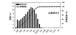
- Graphs showing the particle size distribution of the positive electrode active material of the comparative example are shown in FIGS.
- the vertical axis on the left side of the figure represents the frequency of the bar graph in the figure (%; how many particles having the particle size shown on the horizontal axis are present).
- the vertical axis on the right side of the figure represents the frequency of the line graph in the figure (%; cumulative value of the frequency of presence of particles having the particle size shown on the horizontal axis, which is 100% in total).
- the cumulative frequency of each positive electrode active material is shown in Table 1.
- the particle size distribution of the positive electrode active material of the comparative example is monodisperse having only one peak in the range of 1.5 to 5.5 ⁇ m in particle size.
- the volume cumulative frequency D50 of the positive electrode active material of the comparative example was about 1.7 to 1.9 ⁇ m and was outside the range of 2.0 to 15 ⁇ m.
- the particle size distribution of the positive electrode active material of the example is a polydispersion having a total of two peaks, one for each of the particle diameter range of 1.5 to 5.5 ⁇ m and the particle diameter range of 12 to 30 ⁇ m. is there.
- the volume cumulative frequency D50 of the positive electrode active material of the example was about 3.0 to 6.0 ⁇ m and in the range of 2.0 to 15 ⁇ m. From this result, the peak in the range of 1.5 to 5.5 ⁇ m in particle size is the peak of the mixture particle, and the peak in the range of 12 to 30 ⁇ m in particle size is the peak of secondary particles obtained by the heating and pressurizing step. It is guessed that. In addition, in the positive electrode active material of the example, it is considered that D50 is increased by the mixture particles forming secondary particles in the heating and pressurizing step.
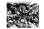
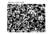
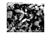
- the positive electrode active material of the example shown in FIGS. 9 and 10 has a large amount of aggregation of particles as compared with the positive electrode active material of the comparative example shown in FIGS. Also from this result, it is understood that the positive electrode active material of the example contains an aggregate of mixture particles, that is, secondary particles.
- the lithium secondary battery of the example has a smaller internal resistance than the lithium secondary battery of the comparative example. Specifically, while the internal resistance of the lithium secondary battery of the comparative example was 34.723 ⁇ , the internal resistance of the lithium secondary battery of the example was 27.62 ⁇ .
- the difference between the lithium secondary battery of the example and the lithium secondary battery of the comparative example is only the positive electrode active material, so it can be said that the positive electrode active material of the example has excellent conductivity compared to the positive electrode active material of the comparative example. That is, from this result, it is understood that by performing the mixing step and the heating and pressing step, the adhesion between the lithium silicate based compound and the carbon material can be improved, and a positive electrode active material excellent in conductivity can be manufactured.
- the lithium secondary battery of the example Since the difference between the lithium secondary battery of the example and the lithium secondary battery of the comparative example is only the positive electrode active material, it is considered that the difference between the positive electrode active material affects the charge and discharge capacity.
- the lithium ion secondary battery of the example has a lower average voltage at the time of initial charge as compared with the comparative example. For this reason, the lithium ion secondary battery of the embodiment is advantageous when performing charging and discharging with a reduced charging voltage for the purpose of reducing the load on the electrolytic solution. Therefore, from this result, by subjecting the lithium silicate compound and the carbon material to the mixing step and the heating and pressing step, a positive electrode active material having excellent conductivity can be produced, and a non-aqueous electrolyte secondary battery having a larger capacity is produced.
- the positive electrode active material of the present invention having the lithium silicate compound and the carbon material as materials and having two peaks in the particle size distribution is useful as a positive electrode active material for a non-aqueous electrolyte secondary battery.
Landscapes
- Chemical & Material Sciences (AREA)
- Chemical Kinetics & Catalysis (AREA)
- Electrochemistry (AREA)
- General Chemical & Material Sciences (AREA)
- Composite Materials (AREA)
- Engineering & Computer Science (AREA)
- Manufacturing & Machinery (AREA)
- Crystallography & Structural Chemistry (AREA)
- Inorganic Chemistry (AREA)
- Battery Electrode And Active Subsutance (AREA)
Abstract
Description
レーザー回折散乱式粒度分布測定法による粒径分布において2つのピークを持つことを特徴とする。
該混合工程後の混合物を、500~750℃、1~500MPaで1分~15時間加熱および加圧する加熱加圧工程と、を備えることを特徴とする。
混合工程においては、リチウムシリケート系化合物と炭素材料とをよく混合する。具体的には、これらの材料を、450~16000rpmで1分~10時間混合する。ここでいう回転数とは、攪拌子の回転数である。この工程によって、リチウムシリケート系化合物と炭素材料とに機械的エネルギーが作用し、これらの材料が互いに摩擦したり圧縮したりして(或いはその他の作用を受けて)複合化することで、粒子状の混合物が得られる。この工程で得られたリチウムシリケート系化合物と炭素材料との混合物を混合物粒子と呼ぶ。
メカノフュージョン処理は、複数の異なる粒子間に機械的エネルギー(機械的歪力)を加えて狭い隙間に繰り返し高速で通過させることにより、複数の異なる粒子が結着した混合物粒子を作製する処理方法である。本発明においては、リチウムシリケート系化合物(すなわち電極活物質)と炭素材料(すなわち導電材)とを含む原料混合物に少なくとも圧縮力と剪断力とを加えることによって、リチウムシリケート系化合物と炭素材料とを結着させ、混合物粒子を得る処理をいう。図1に一般的なメカノフュージョン装置の概略図を示す。以下、図1を基に、メカノフュージョン装置を説明する。
通電焼結法(通電接合法)としては、放電プラズマ焼結法(SPS;Spark Plasma Sintering)、放電焼結法、プラズマ活性化焼結法等と称される直流パルス電流を通電する加圧焼結法が知られている。具体的には、通電焼結法は、導電性を有する加熱加圧型に試料(本発明においては混合物粒子)を充填し、試料を加圧しながらパルス状ON-OFF直流電流を通電することによって、加圧下における通電焼結を行うものであれば良い。かかる通電焼結装置およびその作動原理は、例えば、特開平10-251070号公報に開示されている。
本発明の正極活物質は、リチウムシリケート系化合物と炭素材料とを含み、非水電解質二次電池正極用活物質として有効に使用できる。この正極活物質を含む正極は、通常の非水電解質二次電池用正極と同様の構造にできる。
上記した正極活物質を含む正極を用いる非水電解質二次電池は、公知の手法により製造することができる。例えば非水電解質二次電池がリチウム二次電池やリチウムイオン二次電池であれば、正極材料として上記した正極を使用し、負極材料(負極活物質)としてリチウムイオンを吸蔵および放出可能であってリチウムと合金化可能な元素および/またはリチウムと合金化可能な元素を含む元素化合物を用いれば良い。或いは、公知の金属リチウム、黒鉛等の炭素系材料、チタン酸リチウム等の酸化物材料を使用しても良い。
<正極活物質の製作>
[混合工程]
リチウムシリケート系化合物としてのLi2FeSiO4100質量部と、炭素材料としてのAB10質量部とを、メカノフュージョン装置(ホソカワミクロン株式会社製)で混合し、混合物粒子を得た。このときの処理条件は、隙間(クリアランス)1mm、6000rpm、キャリアーガス(N2)流量0.220L/分、処理時間10分間であった。
混合工程で得た混合物粒子を直径15mmのペレット状に成形した。このペレットをSPS装置(住友石炭鉱業株式会社[現社名;SPSシンテックス株式会社]製)を用いて加熱・加圧処理した。このときの処理条件は、処理温度700℃、処理時間5分間、圧力30MPa、通電電流480Aであった。なお、このとき昇温速度200℃/分で700℃まで加熱して、700℃で5分間保持した。この工程で、実施例の非水電解質二次電池用正極活物質を得た。
上記の工程で製造した正極活物質を用い、評価用のリチウム二次電池を製作した。
詳しくは、正極活物質:アセチレンブラック(AB):ポリテトラフルオロエチレン(PTFE)=17.1:4.7:1(質量比)の混合物を混練した後フィルム状にして、アルミニウム製の集電体に圧着して電極を製作し、140℃で3時間真空乾燥したものを正極として用いた。負極としては、金属リチウムを用いた。電解液としては、エチレンカーボネート(EC):ジメチレンカーボネート(DMC)=1:1にLiPF6を溶解して1mol/Lとした溶液を用いた。
比較例の正極活物質は、実施例の混合工程で得た混合物粒子であり、加熱加圧工程に供さなかったものである。比較例のリチウム二次電池は、正極活物質以外は実施例のリチウム二次電池と同じものである。
[嵩密度測定試験]
実施例の正極活物質および比較例の正極活物質について、メスシリンダーを用いて嵩密度(タップ密度)を測定した。その際、実施例の正極活物質および比較例の正極活物質について、質量およびメスシリンダーを振動させる回数を等しくした。その結果、混合工程のみを行った比較例の正極活物質のタップ密度は0.48g/cm3であったのに対し、混合工程と加熱加圧工程とを行った実施例の正極活物質のタップ密度は1.39g/cm3と非常に大きかった(約2.9倍)。この結果から、加熱加圧工程により正極活物質の嵩密度を大きくできることがわかる。
実施例の正極活物質および比較例の正極活物質について、レーザー回折散乱式粒度分布測定法により粒度分布(粒径分布および累積頻度)を測定した。装置としては日機装株式会社製のAEROTRAC SPR MODEL 7340を用いた。各試料につき3回ずつ粒度分布を測定した。実施例の正極活物質の粒度分布を表すグラフを図3~5に示す。比較例の正極活物質の粒度分布を表すグラフを図6~8に示す。なお、図中左側の縦軸は図中棒グラフの度数(%;横軸に示す粒径を持つ粒子が、それぞれどの程度存在するか)を表す。図中右側の縦軸は図中折れ線グラフの度数(%;横軸に示す粒径を持つ粒子が存在する頻度の累積値であり、全体で100%となる)を表す。各正極活物質の累積頻度を表1に示す。

実施例の正極活物質および比較例の正極活物質について、走査型電子顕微鏡(SEM;Scanning Electron Microscope)による表面観察を行った。実施例の正極活物質のSEM像を図9および10に示し、比較例の正極活物質のSEM像を図11および12に示す。なお、図9および11の倍率は10000倍であり、図10および12の倍率は20000倍である。
実施例および比較例のリチウム二次電池について、充電後の内部抵抗(インピーダンス)を測定した。具体的には、電気化学測定装置(Solarton社製 SI1280B)を用いて、0.1Hz~20000Hz、交流10mVで測定した。測定結果を図13に示す。
実施例および比較例のリチウム二次電池について30℃で繰り返し充放電を行った。各電池に、正極活物質の単位面積(1cm2)あたり0.05mAに相当する電流値で充放電を行った。その際の放電終止電圧は1.5V、充電終止電圧は4.5V(但し初回のみ4.8V)とした。実施例のリチウム二次電池の充放電曲線を図14に示し比較例のリチウム二次電池の充放電曲線を図15に示す。図14、15に示すように、実施例のリチウム二次電池は、比較例のリチウム二次電池に比べて充放電容量が大きい。実施例のリチウム二次電池と比較例のリチウム二次電池との違いは正極活物質のみであるため、正極活物質の違いが充放電容量に影響していると考えられる。また、実施例のリチウムイオン二次電池は、比較例に比べて、初期充電時の平均電圧が低い。このため、実施例のリチウムイオン二次電池は、電解液への負荷を低減させる目的で充電電圧を下げた充放電を行う場合に有利になる。したがってこの結果から、リチウムシリケート系化合物と炭素材料とに混合工程と加熱加圧工程とを施すことで、導電性に優れる正極活物質を製造でき、容量のさらに大きな非水電解質二次電池を製造できることがわかる。換言すると、リチウムシリケート系化合物と炭素材料とを材料とし、粒径分布において2つのピークを持つ本発明の正極活物質は、非水電解質二次電池用正極活物質として有用である。
Claims (9)
- リチウム(Li)、ケイ素(Si)、酸素(O)および2価の遷移金属元素を含むリチウムシリケート系化合物と、炭素(C)を含む炭素材料と、からなり、
レーザー回折散乱式粒度分布測定法による粒径分布において2つのピークを持つことを特徴とする非水電解質二次電池用正極活物質。 - 前記2価の遷移金属元素は鉄(Fe)、マンガン(Mn)、コバルト(Co)から選ばれる少なくとも一種である請求項1に記載の非水電解質二次電池用正極活物質。
- レーザー回折/散乱式粒度分布測定法による粒径分布において、1.5μm以上5.5μm以下の範囲、および、12μm以上30μm以下の範囲にピークを持つ請求項2に記載の非水電解質二次電池用正極活物質。
- 嵩密度が1.0g/cm3以上である請求項1~請求項3の何れか一つに記載の非水電解質二次電池用正極活物質。
- レーザー回折/散乱式粒度分布測定法による体積累積頻度D50の値は2.0μm以上15μm以下である請求項1~請求項4の何れか一つに記載の非水電解質二次電池用正極活物質。
- 請求項1~5の何れか一つに記載の正極活物質を正極に含むことを特徴とする非水電解質二次電池。
- 請求項6に記載の非水電解質二次電池を搭載していることを特徴とする車両。
- リチウム(Li)、ケイ素(Si)、酸素(O)および2価の遷移金属元素を含むリチウムシリケート系化合物と、炭素(C)を含む炭素材料と、を450~16000rpmで1分~10時間混合する混合工程と、
該混合工程後の混合物を、500~750℃、1~500MPaで1分~15時間加熱および加圧する加熱加圧工程と、を備えることを特徴とする非水電解質二次電池用正極活物質の製造方法。 - 前記混合工程および/または前記加熱加圧工程は、不活性雰囲気でおこなう請求項8に記載の非水電解質二次電池用正極活物質の製造方法。
Priority Applications (2)
| Application Number | Priority Date | Filing Date | Title |
|---|---|---|---|
| US14/122,023 US20140127585A1 (en) | 2011-05-26 | 2012-03-16 | Positive electrode active material for nonaqueous electrolyte secondary battery, nonaqueous electrolyte secondary battery, vehicle, and process for producing nonaqueous electrolyte secondary battery positive electrode active material |
| JP2013516172A JP5733805B2 (ja) | 2011-05-26 | 2012-03-16 | 非水電解質二次電池用正極活物質、および非水電解質二次電池用正極活物質の製造方法 |
Applications Claiming Priority (2)
| Application Number | Priority Date | Filing Date | Title |
|---|---|---|---|
| JP2011117854 | 2011-05-26 | ||
| JP2011-117854 | 2011-05-26 |
Publications (1)
| Publication Number | Publication Date |
|---|---|
| WO2012160738A1 true WO2012160738A1 (ja) | 2012-11-29 |
Family
ID=47216833
Family Applications (1)
| Application Number | Title | Priority Date | Filing Date |
|---|---|---|---|
| PCT/JP2012/001841 Ceased WO2012160738A1 (ja) | 2011-05-26 | 2012-03-16 | 非水電解質二次電池用正極活物質、非水電解質二次電池、車両、および非水電解質二次電池用正極活物質の製造方法 |
Country Status (4)
| Country | Link |
|---|---|
| US (1) | US20140127585A1 (ja) |
| JP (1) | JP5733805B2 (ja) |
| TW (1) | TW201304258A (ja) |
| WO (1) | WO2012160738A1 (ja) |
Cited By (4)
| Publication number | Priority date | Publication date | Assignee | Title |
|---|---|---|---|---|
| JP2013252995A (ja) * | 2012-06-07 | 2013-12-19 | National Institute Of Advanced Industrial Science & Technology | リチウムマンガン複合酸化物、及びその炭素複合体 |
| JP2014096345A (ja) * | 2012-10-12 | 2014-05-22 | Taiheiyo Cement Corp | 二次電池用正極材活物質の製造方法 |
| JP2016504727A (ja) * | 2012-12-14 | 2016-02-12 | ユミコア | 充電式電池用の低空隙率電極 |
| JPWO2021153077A1 (ja) * | 2020-01-31 | 2021-08-05 |
Families Citing this family (3)
| Publication number | Priority date | Publication date | Assignee | Title |
|---|---|---|---|---|
| JP6456630B2 (ja) * | 2013-09-18 | 2019-01-23 | 株式会社東芝 | 非水電解質電池 |
| KR20150134259A (ko) * | 2014-05-21 | 2015-12-01 | 주식회사 에너세라믹 | 리튬복합금속산화물 및 이를 포함하는 리튬이차전지 |
| CN119069621B (zh) * | 2023-05-31 | 2025-12-23 | 比亚迪股份有限公司 | 正极片及其制备方法、锂电池和车辆 |
Citations (6)
| Publication number | Priority date | Publication date | Assignee | Title |
|---|---|---|---|---|
| JP2007335325A (ja) * | 2006-06-16 | 2007-12-27 | Kyushu Univ | 非水電解質二次電池用正極活物質及び電池 |
| JP2008218303A (ja) * | 2007-03-07 | 2008-09-18 | Kyushu Univ | 二次電池用正極活物質の製造方法 |
| JP2008293661A (ja) * | 2007-05-22 | 2008-12-04 | Nec Tokin Corp | リチウム二次電池用正極及びそれを用いたリチウム二次電池 |
| JP2009076402A (ja) * | 2007-09-21 | 2009-04-09 | Sumitomo Electric Ind Ltd | リチウム電池 |
| JP2009283354A (ja) * | 2008-05-23 | 2009-12-03 | Panasonic Corp | 非水電解質二次電池用電極およびその製造方法ならびに非水電解質二次電池 |
| WO2010089931A1 (ja) * | 2009-02-04 | 2010-08-12 | 独立行政法人産業技術総合研究所 | リチウムシリケート系化合物の製造方法 |
Family Cites Families (2)
| Publication number | Priority date | Publication date | Assignee | Title |
|---|---|---|---|---|
| WO2008155989A1 (ja) * | 2007-06-21 | 2008-12-24 | Agc Seimi Chemical Co., Ltd. | リチウム含有複合酸化物粉末及びその製造方法 |
| US9431649B2 (en) * | 2009-11-23 | 2016-08-30 | Uchicago Argonne, Llc | Coated electroactive materials |
-
2012
- 2012-03-16 WO PCT/JP2012/001841 patent/WO2012160738A1/ja not_active Ceased
- 2012-03-16 US US14/122,023 patent/US20140127585A1/en not_active Abandoned
- 2012-03-16 JP JP2013516172A patent/JP5733805B2/ja not_active Expired - Fee Related
- 2012-05-25 TW TW101118628A patent/TW201304258A/zh unknown
Patent Citations (6)
| Publication number | Priority date | Publication date | Assignee | Title |
|---|---|---|---|---|
| JP2007335325A (ja) * | 2006-06-16 | 2007-12-27 | Kyushu Univ | 非水電解質二次電池用正極活物質及び電池 |
| JP2008218303A (ja) * | 2007-03-07 | 2008-09-18 | Kyushu Univ | 二次電池用正極活物質の製造方法 |
| JP2008293661A (ja) * | 2007-05-22 | 2008-12-04 | Nec Tokin Corp | リチウム二次電池用正極及びそれを用いたリチウム二次電池 |
| JP2009076402A (ja) * | 2007-09-21 | 2009-04-09 | Sumitomo Electric Ind Ltd | リチウム電池 |
| JP2009283354A (ja) * | 2008-05-23 | 2009-12-03 | Panasonic Corp | 非水電解質二次電池用電極およびその製造方法ならびに非水電解質二次電池 |
| WO2010089931A1 (ja) * | 2009-02-04 | 2010-08-12 | 独立行政法人産業技術総合研究所 | リチウムシリケート系化合物の製造方法 |
Cited By (7)
| Publication number | Priority date | Publication date | Assignee | Title |
|---|---|---|---|---|
| JP2013252995A (ja) * | 2012-06-07 | 2013-12-19 | National Institute Of Advanced Industrial Science & Technology | リチウムマンガン複合酸化物、及びその炭素複合体 |
| JP2014096345A (ja) * | 2012-10-12 | 2014-05-22 | Taiheiyo Cement Corp | 二次電池用正極材活物質の製造方法 |
| JP2016504727A (ja) * | 2012-12-14 | 2016-02-12 | ユミコア | 充電式電池用の低空隙率電極 |
| US10193151B2 (en) | 2012-12-14 | 2019-01-29 | Umicore | Low porosity electrodes for rechargeable batteries |
| US10862121B2 (en) | 2012-12-14 | 2020-12-08 | Umicore | Low porosity electrodes for rechargeable batteries |
| JPWO2021153077A1 (ja) * | 2020-01-31 | 2021-08-05 | ||
| JP7813998B2 (ja) | 2020-01-31 | 2026-02-16 | パナソニックIpマネジメント株式会社 | 二次電池用負極活物質およびその製造方法、ならびに二次電池 |
Also Published As
| Publication number | Publication date |
|---|---|
| TW201304258A (zh) | 2013-01-16 |
| US20140127585A1 (en) | 2014-05-08 |
| JPWO2012160738A1 (ja) | 2014-07-31 |
| JP5733805B2 (ja) | 2015-06-10 |
Similar Documents
| Publication | Publication Date | Title |
|---|---|---|
| JP5256403B2 (ja) | リチウム二次電池用負極活物質粒子と負極及びそれらの製造方法 | |
| TWI569497B (zh) | 鋰離子電池用之負極活性材料及使用該材料之鋰離子電池用之負極 | |
| JP5190916B2 (ja) | 電極用複合粉末及びその製造方法 | |
| JP4992128B2 (ja) | リチウム二次電池用負極活物質粒子および負極の製造方法 | |
| JP6944783B2 (ja) | 全固体電池用電極の製造方法および全固体電池の製造方法 | |
| JP5636526B2 (ja) | リチウムイオン二次電池及びその製造方法 | |
| JP5733805B2 (ja) | 非水電解質二次電池用正極活物質、および非水電解質二次電池用正極活物質の製造方法 | |
| JP5448555B2 (ja) | リチウムイオン二次電池用負極、それを用いたリチウムイオン二次電池、リチウムイオン二次電池用の負極作製用のスラリー、リチウムイオン二次電池用負極の製造方法 | |
| JPWO2018193994A1 (ja) | 全固体リチウムイオン二次電池 | |
| KR20170084271A (ko) | 리튬-철-인-황-탄소 복합체 및 그 제조 방법 | |
| KR20180003577A (ko) | 리튬 이온 이차 전지용 부극 활물질 및 리튬 이온 이차 전지 | |
| JP2019179731A (ja) | 全固体電池負極及び全固体型リチウム二次電池 | |
| JP2019186212A (ja) | 全固体電池負極及び全固体リチウム二次電池 | |
| TW201505241A (zh) | 蓄電裝置用Si系合金負極材料及使用其之電極 | |
| JP4997496B2 (ja) | 電極用複合粉末及びその製造方法 | |
| JP6926943B2 (ja) | 固体電池用負極活物質層 | |
| JP5071919B2 (ja) | 高密度アセチレンブラック及びその製造方法 | |
| JP6422017B2 (ja) | 水素吸蔵合金、電極及びニッケル水素蓄電池 | |
| JP7778420B2 (ja) | 硫化リチウム-鉄-炭素複合体 | |
| JP2025530180A (ja) | 固体電解質の製造方法および固体電解質 | |
| JP2022013953A (ja) | 電極及び固体型リチウムイオン二次電池 | |
| JP6485028B2 (ja) | 電気デバイス用負極活物質、およびこれを用いた電気デバイス | |
| JP4022742B2 (ja) | リチウム電池用負極材料及びその製造方法 | |
| KR101264324B1 (ko) | 리튬이차전지용 주석계 나노복합 음극 활물질의 제조방법 및 이를 이용한 리튬이차전지 | |
| JP7797056B2 (ja) | 鉄含有多硫化リチウム |
Legal Events
| Date | Code | Title | Description |
|---|---|---|---|
| 121 | Ep: the epo has been informed by wipo that ep was designated in this application |
Ref document number: 12789028 Country of ref document: EP Kind code of ref document: A1 |
|
| ENP | Entry into the national phase |
Ref document number: 2013516172 Country of ref document: JP Kind code of ref document: A |
|
| WWE | Wipo information: entry into national phase |
Ref document number: 14122023 Country of ref document: US |
|
| NENP | Non-entry into the national phase |
Ref country code: DE |
|
| 122 | Ep: pct application non-entry in european phase |
Ref document number: 12789028 Country of ref document: EP Kind code of ref document: A1 |