WO2012160779A1 - Pile à combustible - Google Patents
Pile à combustible Download PDFInfo
- Publication number
- WO2012160779A1 WO2012160779A1 PCT/JP2012/003199 JP2012003199W WO2012160779A1 WO 2012160779 A1 WO2012160779 A1 WO 2012160779A1 JP 2012003199 W JP2012003199 W JP 2012003199W WO 2012160779 A1 WO2012160779 A1 WO 2012160779A1
- Authority
- WO
- WIPO (PCT)
- Prior art keywords
- thick film
- electrolyte membrane
- film portion
- fuel cell
- conductive direction
- Prior art date
- Legal status (The legal status is an assumption and is not a legal conclusion. Google has not performed a legal analysis and makes no representation as to the accuracy of the status listed.)
- Ceased
Links
Images






Classifications
-
- H—ELECTRICITY
- H01—ELECTRIC ELEMENTS
- H01M—PROCESSES OR MEANS, e.g. BATTERIES, FOR THE DIRECT CONVERSION OF CHEMICAL ENERGY INTO ELECTRICAL ENERGY
- H01M8/00—Fuel cells; Manufacture thereof
- H01M8/10—Fuel cells with solid electrolytes
- H01M8/1016—Fuel cells with solid electrolytes characterised by the electrolyte material
- H01M8/1018—Polymeric electrolyte materials
- H01M8/1065—Polymeric electrolyte materials characterised by the form, e.g. perforated or wave-shaped
-
- H—ELECTRICITY
- H01—ELECTRIC ELEMENTS
- H01M—PROCESSES OR MEANS, e.g. BATTERIES, FOR THE DIRECT CONVERSION OF CHEMICAL ENERGY INTO ELECTRICAL ENERGY
- H01M8/00—Fuel cells; Manufacture thereof
- H01M8/10—Fuel cells with solid electrolytes
- H01M8/1016—Fuel cells with solid electrolytes characterised by the electrolyte material
- H01M8/1018—Polymeric electrolyte materials
- H01M8/1067—Polymeric electrolyte materials characterised by their physical properties, e.g. porosity, ionic conductivity or thickness
-
- Y—GENERAL TAGGING OF NEW TECHNOLOGICAL DEVELOPMENTS; GENERAL TAGGING OF CROSS-SECTIONAL TECHNOLOGIES SPANNING OVER SEVERAL SECTIONS OF THE IPC; TECHNICAL SUBJECTS COVERED BY FORMER USPC CROSS-REFERENCE ART COLLECTIONS [XRACs] AND DIGESTS
- Y02—TECHNOLOGIES OR APPLICATIONS FOR MITIGATION OR ADAPTATION AGAINST CLIMATE CHANGE
- Y02E—REDUCTION OF GREENHOUSE GAS [GHG] EMISSIONS, RELATED TO ENERGY GENERATION, TRANSMISSION OR DISTRIBUTION
- Y02E60/00—Enabling technologies; Technologies with a potential or indirect contribution to GHG emissions mitigation
- Y02E60/30—Hydrogen technology
- Y02E60/50—Fuel cells
Definitions
- the present invention relates to a fuel cell.
- Fuel cells are devices that generate electrical energy from hydrogen and oxygen, and can achieve high power generation efficiency.
- the main features of the fuel cell are direct power generation that does not go through the process of thermal energy and kinetic energy as in the conventional power generation method, so that high power generation efficiency can be expected even on a small scale, and there is little emission of nitrogen compounds, Noise and vibration are also small, so the environmental performance is good.
- the fuel cell can effectively use the chemical energy of fuel and has environmentally friendly characteristics, so it is expected as an energy supply system for the 21st century, from space use to automobiles and portable devices. It is attracting attention as a promising new power generation system that can be used for various applications from large-scale power generation to small-scale power generation, and technological development is in full swing toward practical application.
- the polymer electrolyte fuel cell is characterized by low operating temperature and high output density compared to other types of fuel cells.
- mobile devices cell phones, notebook personal computers, PDAs, It is expected to be used for power sources such as MP3 players, digital cameras, electronic dictionaries, and electronic books.
- a planar array type fuel cell in which a plurality of single cells are arranged in a planar shape is known.
- a planar array type fuel cell a configuration is known in which a current collecting member for obtaining electrical continuity with the electrodes (anode and cathode) of each single cell is provided not on the exposed surface of the electrode but on the peripheral portion of the electrode.
- the present invention has been made in view of these problems, and an object of the present invention is to provide a technique capable of suppressing a decrease in the conductivity of the electrode without impairing the power generation performance of the fuel cell.
- the fuel cell includes a membrane electrode assembly including an electrolyte membrane, an anode provided on one surface of the electrolyte membrane, and a cathode provided on the other surface of the electrolyte membrane, and a peripheral portion of the membrane electrode assembly.
- a thick film portion having a relatively large thickness is formed on the electrolyte membrane, and individual cracks formed on at least one of the anode and the cathode are formed on the electrolyte membrane.
- the formation of cracks is limited by the thick film portion so that the sum of the lengths of the components in the conductive direction toward the current collector is larger than the sum of the lengths of the components orthogonal to the conductive direction. .
- the deformation of the electrolyte membrane is suppressed by the thick film portion provided in the electrolyte membrane, and the crack generated in the electrode is formed in the conductive direction in the region between the adjacent thick film portions.
- the crack generated in the electrode is formed in the conductive direction in the region between the adjacent thick film portions.
- the thick film portions and the regions other than the thick film portions may be alternately arranged in the direction perpendicular to the conductive direction on the electrolyte membrane in the plane of the electrolyte membrane.
- the thick film portion in the plane of the electrolyte membrane and the regions other than the thick film portion are alternately arranged in the direction perpendicular to the conductive direction on the electrolyte membrane, and on the line perpendicular to the conductive direction, the thick film portion
- the maximum value Q of the length in which the other regions are continuous may be smaller than the length P of the electrolyte membrane in the conductive direction.
- the maximum value R of the length of the continuous thick film portion may be smaller than the maximum value Q on the line orthogonal to the conductive direction in the plane of the electrolyte membrane.
- the thick film portion is arranged in the conductive direction within the plane of the electrolyte membrane and is separated from one of the end portions, and the maximum value S of the separation distance is 1 of the maximum value Q or the length P of the electrolyte membrane in the conductive direction. / 3 may be smaller than the smaller one.
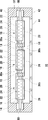
- FIG. 1 is an exploded perspective view showing a structure of a fuel cell according to Embodiment 1.
- FIG. 2 is a cross-sectional view of the fuel cell along the line AA in FIG. 1.
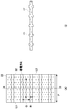
- FIG. 3A is a plan view showing the structure of the electrolyte membrane 22.
- FIG. 3B is a cross-sectional view taken along line BB in FIG.
- FIG. 3 is a plan view showing the generation direction of cracks generated in a catalyst layer according to Embodiment 1.
- 3 is a process diagram illustrating a method for producing a composite membrane used in the fuel cell according to Embodiment 1.
- FIG. 3 is a process diagram illustrating a method for producing a composite membrane used in the fuel cell according to Embodiment 1.
- FIG. 3 is a process diagram illustrating a method for producing a composite membrane used in the fuel cell according to Embodiment 1.
- FIG. 3 is a process diagram illustrating a method for producing a composite membrane used in the fuel cell according to Embodiment 1.
- FIG. 3 is a process diagram illustrating a method for producing a composite membrane used in the fuel cell according to Embodiment 1.
- FIG. 3 is a process diagram illustrating a method for producing a composite membrane used in the fuel cell according to Embodiment 1.
- FIG. 3 is a process diagram illustrating a method for producing a composite membrane used in the fuel cell according to Embodiment 1.
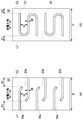
- FIG. 11A is a plan view of the electrolyte membrane according to the second exemplary embodiment.
- FIG. 11B is a plan view of the electrolyte membrane according to the second embodiment.
- FIG. 12A is a plan view of the electrolyte membrane according to the second exemplary embodiment.
- FIG. 12B is a plan view of the electrolyte membrane according to the second embodiment.
- FIG. 1 is an exploded perspective view showing the structure of the fuel cell according to Embodiment 1.
- FIG. FIG. 2 is a sectional view taken along line AA in FIG.
- the fuel cell 10 includes a composite membrane 12, an anode housing 40, and a cathode housing in which a membrane electrode assembly (MEA, also referred to as a catalyst-coated proton exchange membrane (CCM)) 20 is incorporated. 42 is provided. Further, a sealing member 50 described later is provided on the peripheral edge of the composite film 12.
- MEA membrane electrode assembly
- CCM catalyst-coated proton exchange membrane
- the composite film 12 includes a base material 14 and a plurality of membrane electrode assemblies 20.
- the base material 14 is formed of an insulating material such as polyacrylate.
- the base material 14 is provided with the same number of openings 16 as the membrane electrode assembly 20.
- the membrane electrode assembly 20 includes an electrolyte membrane 22, an anode catalyst layer 24 provided on one surface of the electrolyte membrane 22, and a cathode catalyst layer 26 provided on the other surface of the electrolyte membrane 22.
- the electrolyte membrane 22 is provided so as to fill the opening 16 provided in the base material 14. Hydrogen is supplied to the anode catalyst layer 24 as a fuel gas. On the other hand, air is supplied to the cathode catalyst layer 26 as an oxidant.
- a cell is configured by sandwiching the electrolyte membrane 22 between the pair of anode catalyst layer 24 and cathode catalyst layer 26, and each cell generates power by an electrochemical reaction between hydrogen and oxygen in the air.
- the cathode catalyst layer 26 is paired with the anode catalyst layer 24, and a plurality of cells are formed in a planar shape.
- the interconnector (current collecting member) 18 of the present embodiment is provided at the peripheral edge of the membrane electrode assembly 20, and is the main surface of the anode catalyst layer 24 on the side opposite to the electrolyte membrane 22 and the electrolyte membrane 22.
- the cathode catalyst layer 26 on the opposite side is exposed without being covered with the interconnector 18.
- the interconnector 18 is provided through the base material 14 between the adjacent membrane electrode assemblies 20.
- the anode catalyst layer 24 covered with the electrolyte membrane 22 of one cell is provided so as to extend toward the interconnector 18, and the interconnector 18 and the electrolyte membrane 22 of one cell are connected to each other.
- the substrate 14 in between is covered and connected to the interconnector 18.
- the cathode catalyst layer 26 covered with the electrolyte membrane 22 of the other cell is provided to extend toward the interconnector 18, and the electrolyte membrane 22 of the interconnector 18 and the other cell is provided.
- the base material 14 is covered with and connected to the interconnector 18.
- the interconnector 18 is formed of a conductive material, and for example, carbon is used. With the above configuration, adjacent cells are connected in series by the interconnector 18.
- the direction of the current flowing toward the interconnector 18 in the cathode catalyst layer 26 and the direction of the current flowing from the interconnector 18 toward the anode catalyst layer 24 are referred to as a conductive direction.
- the electrolyte membrane 22 preferably exhibits good ionic conductivity in a wet state, and functions as an ion exchange membrane that moves protons between the anode catalyst layer 24 and the cathode catalyst layer 26.
- the electrolyte membrane 22 is formed of a solid polymer material such as a fluorine-containing polymer or a non-fluorine polymer, and for example, a sulfonic acid type perfluorocarbon polymer, a polysulfone resin, a perfluorocarbon polymer having a phosphonic acid group or a carboxylic acid group. Etc. can be used.
- sulfonic acid type perfluorocarbon polymer examples include Nafion (manufactured by DuPont: registered trademark) 112.
- non-fluorine polymers include sulfonated aromatic polyetheretherketone and polysulfone.
- FIG. 3A is a plan view showing the structure of the electrolyte membrane 22.
- FIG. 3B is a cross-sectional view taken along line BB in FIG.
- the electrolyte membrane 22 is partially different in film thickness and has a thick film portion 23 having a relatively thick film thickness.
- the thick film portion 23 is in the form of a strip formed at a predetermined interval along the conductive direction, and the conductive direction from one side L1 of the electrolyte membrane 22 extending in the direction intersecting the conductive direction. And extends to the other side L2 of the electrolyte membrane 22 extending in the direction intersecting with.
- the thick film portion 23 is formed in a convex shape on both the anode side surface and the cathode side surface of the electrolyte membrane 22.
- the thickness of the thick film portion 23 is, for example, 30 to 50 ⁇ m, and the thickness of the electrolyte membrane 22 other than the thick film portion 23 is, for example, 15 to 30 ⁇ m.
- the thickness of the electrolyte membrane 22 is set to an optimum thickness for drawing out the performance of the fuel cell, and the thick film portion 23 is formed thicker than the electrolyte membrane 22 in a range that does not significantly impair the performance of the fuel cell.
- the maximum value Q of the length in which the region other than the thick film portion 23 continues on the line orthogonal to the conductive direction in the plane of the electrolyte membrane 22 is smaller than the length P of the electrolyte membrane 22 in the conductive direction (P / Q> 1).
- the maximum value Q corresponds to the distance between adjacent thick film portions 23.
- the maximum value Q is the maximum length among the intervals between the adjacent thick film portions 23.
- the maximum value R of the width in which the thick film portion 23 continues on the line orthogonal to the conductive direction is smaller than the maximum value Q (Q / R> 1).
- the maximum value R is the width of the thick film portion 23 itself.
- the maximum value R is the maximum width of the thick film portion 23.
- the anode catalyst layer 24 and the cathode catalyst layer 26 have ion-exchange resin, catalyst particles, and possibly carbon particles.
- the ion exchange resin included in the anode catalyst layer 24 and the cathode catalyst layer 26 connects the catalyst particles and the electrolyte membrane 22 and has a role of transmitting protons therebetween.
- This ion exchange resin may be formed of the same polymer material as the electrolyte membrane 22.
- catalyst metals include Sc, Y, Ti, Zr, V, Nb, Fe, Co, Ni, Ru, Rh, Pd, Pt, Os, Ir, alloys selected from lanthanoid series elements and actinoid series elements, A simple substance is mentioned.
- acetylene black, ketjen black, carbon nanotubes or the like may be used as the carbon particles.
- the ion exchange resin included in the anode catalyst layer 24 and the cathode catalyst layer 26 may have a smaller number of C—F bonds than the resin contained in the base material 14, for example, a hydrocarbon ion exchange resin. Good.
- a fuel storage portion 37 for storing fuel is formed by the anode housing 40.
- fuel supply port (not shown) in the anode housing 40, fuel can be appropriately replenished from a fuel cartridge or the like.
- the cathode housing 42 is provided with an air intake 44 for taking in air from the outside.
- the anode housing 40 and the cathode housing 42 are fastened by using fastening members (not shown) such as bolts and nuts via a sealing member 50 provided at the peripheral edge of the composite film 12. Thereby, pressure is applied to the sealing member 50 and the sealing performance by the sealing member 50 is enhanced.
- an insulating protective layer 30a is provided around the anode catalyst layer 24, particularly on the base material 14 between the adjacent anode catalyst layers 24.
- a protective layer 30 b is provided around the cathode catalyst layer 26, particularly on the base material 14 between the adjacent cathode catalyst layers 26.
- the protective layers 30a and 30b may be collectively referred to as the protective layer 30.
- the protective layer 30 for example, polyimide, Nafion, or the like can be used.
- the insulating property between the adjacent membrane electrode assemblies 20 is enhanced by the protective layer 30. As a result, even if the gap between the adjacent membrane electrode assemblies 20, in other words, the adjacent cells is narrowed, occurrence of a short circuit between the adjacent cells is suppressed.
- the deformation of the electrolyte membrane 22 is suppressed by providing the electrolyte membrane 22 with the thick film portion 23 having the above-described anisotropy, In the region between the adjacent thick film portions 23, it is limited to be formed in the conductive direction. In other words, a crack having anisotropy is formed such that the ratio of the conductive direction becomes longer than the ratio of the direction orthogonal to the conductive direction. For this reason, without using a member that does not contribute to power generation, it is possible to suppress the development of cracks in the direction orthogonal to the conductive direction in the electrode, and as a result, it is possible to more reliably secure the conductive path in the conductive direction.
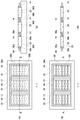
- FIGS. 5 to 10 are process diagrams showing a method of manufacturing the composite film 12 according to the first embodiment. 5 to 10, the left side (i) shows a plan view, and the right side (ii) shows a cross-sectional view along the line AA of the plan view.
- a base material 14 is prepared.
- the substrate 14 has a thickness of 20 to 150 ⁇ m.
- the base material 14 for example, polyacrylate can be used.
- a plurality of openings 16 and 17 are formed in the base material.
- the opening 17 is formed between the adjacent openings 16.
- the distance between the opening 16 and the opening 17 is 500 ⁇ m or less.
- a technique such as laser processing using an infrared laser, a visible light laser, or an ultraviolet laser or a punching method using a mold can be used.
- a protective layer 30a and a protective layer 30b are prepared.
- the protective layer 30a is provided with an opening 31a corresponding to a region where the anode catalyst layer is provided.
- the protective layer 30b is provided with an opening 31b corresponding to a region where the cathode is provided.
- a method for producing the protective layers 30a and 30b for example, a method of providing an opening in a sheet-like protective layer using a laser or a mold can be cited.
- the protective layer 30a and the protective layer 30b have shielding properties, heat resistance, and thermal conductivity with respect to a laser used in laser processing to be described later.
- materials for the protective layer 30a and the protective layer 30b for example, A phenol resin, a polyimide, and a cellulose are mentioned.
- a protective layer 30a is overlaid on one surface (anode formation side) of the substrate 14, and a protective layer 30b is disposed on the other surface (cathode formation side) of the substrate 14.
- the protective layers 30a and 30b are bonded to the base material 14 using a hot press or the like.
- the procedure for attaching the protective layer 30 having the opening formed in advance to the base material 14 is taken, but using a mask in which the region where the protective layer 30 is formed becomes an opening, A procedure of applying a resin as a material for the protective layer to the substrate 14 using a spray method or the like is also applicable.
- a pedestal 300 having a groove 302 having a pattern corresponding to the thick film portion 23 of the electrolyte membrane 22 is prepared, and the base material 14 is positioned in a predetermined region of the pedestal 300. Put them together.
- an electrolyte membrane 22 is formed in the opening 16 provided in the base material 14 (see FIG. 7A). Specifically, the opening 16 is filled with a Nafion solution. At this time, the groove 302 formed in the base 300 is also filled with the Nafion solution.
- the electrolyte film 22 having the thick film portion 23 is formed by evaporating the solvent.
- the surface tension acts on the Nafion solution, so that the thick film portion 23 becomes convex with respect to both main surfaces or one main surface of the electrolyte membrane 22.
- an opening 17 (see FIG. 7 (B)) provided in the base material 14 is filled with a paste such as a carbon paste.
- the interconnector 18 is formed by filling the paste and then drying it.
- a catalyst layer 80 is formed along the longitudinal direction of the base material 14 so as to straddle the plurality of electrolyte membranes 22 on one surface side of the base material 14.
- catalyst slurry is prepared by sufficiently stirring 10 g of water, 5 g of Nafion solution, 5 g of platinum black or platinum-supporting carbon, and 5 g of 1-propanol, and the catalyst layer 80 is formed by spraying this catalyst slurry.
- the catalyst layer 82 is formed along the longitudinal direction of the base material 14 so as to straddle the plurality of electrolyte membranes 22 on the other main surface side of the base material 14.
- the catalyst layer 82 is formed by spray coating the catalyst slurry described above.
- a protective layer 30a located in a predetermined region of the catalyst layer 80 provided on one surface side of the base material 14, that is, a region sandwiched between adjacent electrolyte membranes 22.
- the catalyst layer 80 corresponding to the above is partially removed using a laser such as an excimer laser (the width for removing the catalyst layer 80 is 1 to 500 ⁇ m, preferably 50 to 200 ⁇ m).
- the protective layer 30a is exposed in a region sandwiched between the adjacent electrolyte membranes 22, and the anode catalyst layer 24 is formed.
- a catalyst layer 82 corresponding to the protective layer 30b located in a predetermined region of the catalyst layer 82 provided on the other surface side of the base material 14, that is, a region sandwiched between the adjacent electrolyte membranes 22, is formed by an excimer laser or the like. Partial removal using a laser (the width for removing the catalyst layer 82 is 1 to 500 ⁇ m, preferably 50 to 200 ⁇ m). By dividing the catalyst layer 82, the protective layer 30b is exposed in a region sandwiched between the adjacent electrolyte membranes 22, and the cathode catalyst layer 26 is formed.
- a YAG third high frequency laser or a YVO 4 fourth high frequency green laser having an oscillation wavelength of 180 nm or more and 550 nm or less may be used as the laser used for removing the catalyst layer.
- the laser output only needs to be sufficient to completely remove the catalyst layer at the laser irradiation portion, and may be appropriately adjusted according to the material and thickness of the catalyst layer.
- the base material 14 is protected by the protective layer 30a when the catalyst layer 80 is partially removed by laser processing, deterioration of the base material 14 is suppressed. Moreover, since the base material 14 is protected by the protective layer 30b when the catalyst layer 82 is partially removed by laser processing, the deterioration of the base material 14 is suppressed.
- the composite membrane 12 incorporating the membrane electrode assembly 20 according to the first embodiment is produced.
- the same process is performed on the anode and the cathode in each process, and then the next process is performed.
- the process is performed on the cathode. May be applied.
- the step of forming the protective layer 30 may be after the base material 14 is filled with the electrolyte membrane 22 in advance.
- the thick film portion 23 of the electrolyte membrane 22 is formed in a linear strip shape, but the form of the thick film portion 23 is not limited to this and can take various forms. In the following embodiment, the thick film part 23 formed in the electrolyte membrane 22 is illustrated.
- FIG. 11A is a plan view showing an electrolyte membrane 22 according to the second embodiment.
- the thick film portions 23a and the thick film portions 23b are alternately formed at intervals in a direction orthogonal to the conductive direction.
- the thick film portion 23a and the thick film portion 23b are in the form of a band in which a transverse region and a curved region extending in the conductive direction are combined.
- One end of the thick film portion 23a (the end of the transverse region) reaches one side L1 of the electrolyte membrane 22 extending in the direction intersecting the conductive direction, and the other end of the thick film portion 23a.
- End of the curved region is separated from the other side L2 of the electrolyte membrane 22 extending in a direction intersecting the conductive direction.
- One end (the end of the transverse region) of the thick film portion 23b reaches the side L2, and the other end (the end of the curved region) of the thick film portion 23b is separated from the side L1.
- the bending direction of the curved region of the thick film part 23a is opposite to the bending direction of the curved region of the thick film part 23b in the direction orthogonal to the conductive direction.
- the distance between the end of the curved region of the thick film part 23a and the transverse region of the adjacent thick film part 23b is smaller than the distance between the transverse region of the thick film part 23a and the transverse region of the thick film part 23b. Yes. Further, the distance between the end of the curved region of the thick film part 23b and the transverse region of the adjacent thick film part 23a is narrower than the distance between the transverse region of the thick film part 23a and the transverse region of the thick film part 23b. It has become.
- FIG. 11B is a plan view showing the electrolyte membrane 22 according to the third embodiment.
- the thick film portion 23 has an S shape in which a transverse region and a curved region are combined, and one end portion thereof is close to the side L1 while being separated from the side L1. Further, the other end of the thick film portion 23 is close to the side L2 while being separated from the side L2.
- the transverse regions of the thick film portion 23 are arranged in parallel at a predetermined interval.
- FIG. 12A is a plan view showing the electrolyte membrane 22 according to the fourth embodiment.
- the thick film portion 23a and the thick film portion 23b have a U shape in which two transverse regions and a curved region are combined, and the curved region of the thick film portion 23a is separated from the side L1. It is close to the side L1. Further, the two transverse regions of the thick film portion 23a extend from the curved region toward the side L2, and the end portions of the transverse region are separated from the side L2. Further, the curved region of the thick film portion 23b is close to the side L2 while being separated from the side L2.
- the two transverse regions of the thick film portion 23b extend from the curved region toward the side L1, and the ends of the transverse region are separated from the side L1.
- the transverse region of the thick film part 23a and the transverse region of the thick film part 23b are arranged so as to overlap in a direction orthogonal to the conductive direction.
- Thick film portion 23 of Embodiments 2 to 4 does not extend from side L1 to side L2, and is separated from side L1 on side L1 side, separated from side L2 on side L2 side, or Both embodiments are different from the first embodiment in that the belt-like thick film portion 23 is curved.
- the larger one of the maximum length S1 from the side L1 to the thick film portion 23 and the maximum length S2 from the side L2 to the thick film portion 23 in the conductive direction within the surface of the electrolyte membrane 22 is Q or P / 3.
- the thick film portion 23 side does not need to extend from L1 to the side L2, and the thick film portion
- the 23 transverse regions need not be linear.
- the maximum value R in Embodiments 2 to 4 is defined as the maximum value of the width in which the thick film portion 23 continues on a line orthogonal to the conductive direction in a linear region extending in the conductive direction.
- FIG. 12B is a plan view showing the electrolyte membrane 22 according to the fifth embodiment.
- the thick film portion 23 of the present embodiment is in the form of a strip extending from the side L1 to the side L2, it is common to the electrolyte membrane 22 of the first embodiment, but the strip-shaped thick film portion 23 is wavy. This is different from the first embodiment.
- the thick film portion 23 does not have to be linear as long as the relationship of P / Q> 1 or Q / R> 1 is satisfied.
- the ratio of the conductive direction in both the anode catalyst layer 24 and the cathode catalyst layer 26 is dominant with respect to the ratio in the direction orthogonal to the conductive direction due to the thick film portion 23.
- cracks having such anisotropy are formed, even if such cracks are formed in one of the anode catalyst layer 24 and the cathode catalyst layer 26, the above-described effects are exhibited.
- the present invention can be used in the fuel cell field.
Landscapes
- Life Sciences & Earth Sciences (AREA)
- Engineering & Computer Science (AREA)
- Manufacturing & Machinery (AREA)
- Sustainable Development (AREA)
- Sustainable Energy (AREA)
- Chemical & Material Sciences (AREA)
- Chemical Kinetics & Catalysis (AREA)
- Electrochemistry (AREA)
- General Chemical & Material Sciences (AREA)
- Fuel Cell (AREA)
- Inert Electrodes (AREA)
Abstract
Priority Applications (2)
| Application Number | Priority Date | Filing Date | Title |
|---|---|---|---|
| US14/112,753 US9385389B2 (en) | 2011-05-20 | 2012-05-16 | Fuel cell |
| JP2013516193A JP6005635B2 (ja) | 2011-05-20 | 2012-05-16 | 燃料電池 |
Applications Claiming Priority (2)
| Application Number | Priority Date | Filing Date | Title |
|---|---|---|---|
| JP2011113545 | 2011-05-20 | ||
| JP2011-113545 | 2011-05-20 |
Publications (1)
| Publication Number | Publication Date |
|---|---|
| WO2012160779A1 true WO2012160779A1 (fr) | 2012-11-29 |
Family
ID=47216872
Family Applications (1)
| Application Number | Title | Priority Date | Filing Date |
|---|---|---|---|
| PCT/JP2012/003199 Ceased WO2012160779A1 (fr) | 2011-05-20 | 2012-05-16 | Pile à combustible |
Country Status (3)
| Country | Link |
|---|---|
| US (1) | US9385389B2 (fr) |
| JP (1) | JP6005635B2 (fr) |
| WO (1) | WO2012160779A1 (fr) |
Cited By (1)
| Publication number | Priority date | Publication date | Assignee | Title |
|---|---|---|---|---|
| JP2014530468A (ja) * | 2011-09-23 | 2014-11-17 | ソシエテ ビックSociete Bic | 複合材表面に燃料電池のアレイを形成する方法 |
Citations (3)
| Publication number | Priority date | Publication date | Assignee | Title |
|---|---|---|---|---|
| JP2005174770A (ja) * | 2003-12-11 | 2005-06-30 | Nec Corp | 燃料電池 |
| JP2005174620A (ja) * | 2003-12-09 | 2005-06-30 | Hitachi Ltd | 膜電極接合体及びこれを用いた燃料電池 |
| JP2006331720A (ja) * | 2005-05-24 | 2006-12-07 | Hitachi Ltd | 高分子膜およびその製造方法 |
Family Cites Families (5)
| Publication number | Priority date | Publication date | Assignee | Title |
|---|---|---|---|---|
| GB9708365D0 (en) | 1997-04-25 | 1997-06-18 | Johnson Matthey Plc | Proton conducting membranes |
| EP1689014A1 (fr) * | 2005-02-04 | 2006-08-09 | Paul Scherrer Institut | Procédé de fabrication d'une membrane pour l'ensemble electrode-membrane et ensemble membrane-électrode |
| JP2006252967A (ja) | 2005-03-10 | 2006-09-21 | Nissan Motor Co Ltd | 燃料電池用固体高分子電解質膜、および、これを用いた燃料電池 |
| JP2014102876A (ja) * | 2011-02-28 | 2014-06-05 | Sanyo Electric Co Ltd | 燃料電池 |
| US9935327B2 (en) * | 2011-03-14 | 2018-04-03 | Sanyo Electric Co., Ltd. | Fuel cell and method for producing the same |
-
2012
- 2012-05-16 WO PCT/JP2012/003199 patent/WO2012160779A1/fr not_active Ceased
- 2012-05-16 US US14/112,753 patent/US9385389B2/en not_active Expired - Fee Related
- 2012-05-16 JP JP2013516193A patent/JP6005635B2/ja not_active Expired - Fee Related
Patent Citations (3)
| Publication number | Priority date | Publication date | Assignee | Title |
|---|---|---|---|---|
| JP2005174620A (ja) * | 2003-12-09 | 2005-06-30 | Hitachi Ltd | 膜電極接合体及びこれを用いた燃料電池 |
| JP2005174770A (ja) * | 2003-12-11 | 2005-06-30 | Nec Corp | 燃料電池 |
| JP2006331720A (ja) * | 2005-05-24 | 2006-12-07 | Hitachi Ltd | 高分子膜およびその製造方法 |
Cited By (1)
| Publication number | Priority date | Publication date | Assignee | Title |
|---|---|---|---|---|
| JP2014530468A (ja) * | 2011-09-23 | 2014-11-17 | ソシエテ ビックSociete Bic | 複合材表面に燃料電池のアレイを形成する方法 |
Also Published As
| Publication number | Publication date |
|---|---|
| US20140038079A1 (en) | 2014-02-06 |
| JP6005635B2 (ja) | 2016-10-12 |
| US9385389B2 (en) | 2016-07-05 |
| JPWO2012160779A1 (ja) | 2014-07-31 |
Similar Documents
| Publication | Publication Date | Title |
|---|---|---|
| JP5430958B2 (ja) | 膜電極接合体および燃料電池 | |
| JP5442481B2 (ja) | 複合膜、燃料電池および複合膜の作製方法 | |
| US8900774B2 (en) | Fuel cell layer, fuel cell system and method for fabricating the fuel cell layer | |
| US8795919B2 (en) | Fuel cell layer | |
| US7875405B2 (en) | Side-by-side fuel cells | |
| JP5548474B2 (ja) | 複合膜および燃料電池 | |
| US20110294031A1 (en) | Composite membrane and fuel cell | |
| JP5838570B2 (ja) | 固体高分子形燃料電池における膜電極接合体 | |
| JP2011054301A (ja) | 複合膜、膜電極接合体、燃料電池、複合膜の作製方法および膜電極接合体の作製方法 | |
| JP6005635B2 (ja) | 燃料電池 | |
| JP5865346B2 (ja) | 燃料電池および燃料電池の製造方法 | |
| WO2012117661A1 (fr) | Pile à combustible | |
| JP2010238574A (ja) | 複合膜および燃料電池 | |
| US20130337362A1 (en) | Fuel cell and method for producing the same | |
| WO2013080421A1 (fr) | Pile à combustible à oxydation directe et procédé de production d'un ensemble de couches de membrane-catalyseur utilisé dans celle-ci | |
| WO2013080537A1 (fr) | Couche de piles à combustible | |
| JP2010086682A (ja) | 燃料電池 |
Legal Events
| Date | Code | Title | Description |
|---|---|---|---|
| 121 | Ep: the epo has been informed by wipo that ep was designated in this application |
Ref document number: 12789221 Country of ref document: EP Kind code of ref document: A1 |
|
| ENP | Entry into the national phase |
Ref document number: 2013516193 Country of ref document: JP Kind code of ref document: A |
|
| WWE | Wipo information: entry into national phase |
Ref document number: 14112753 Country of ref document: US |
|
| NENP | Non-entry into the national phase |
Ref country code: DE |
|
| 122 | Ep: pct application non-entry in european phase |
Ref document number: 12789221 Country of ref document: EP Kind code of ref document: A1 |