WO2012160816A1 - Bougie à incandescence et procédé pour fabriquer une bougie à incandescence - Google Patents
Bougie à incandescence et procédé pour fabriquer une bougie à incandescence Download PDFInfo
- Publication number
- WO2012160816A1 WO2012160816A1 PCT/JP2012/003350 JP2012003350W WO2012160816A1 WO 2012160816 A1 WO2012160816 A1 WO 2012160816A1 JP 2012003350 W JP2012003350 W JP 2012003350W WO 2012160816 A1 WO2012160816 A1 WO 2012160816A1
- Authority
- WO
- WIPO (PCT)
- Prior art keywords
- sheath tube
- glow plug
- seal
- heating element
- diameter
- Prior art date
- Legal status (The legal status is an assumption and is not a legal conclusion. Google has not performed a legal analysis and makes no representation as to the accuracy of the status listed.)
- Ceased
Links
Images


Classifications
-
- F—MECHANICAL ENGINEERING; LIGHTING; HEATING; WEAPONS; BLASTING
- F23—COMBUSTION APPARATUS; COMBUSTION PROCESSES
- F23Q—IGNITION; EXTINGUISHING-DEVICES
- F23Q7/00—Incandescent ignition; Igniters using electrically-produced heat, e.g. lighters for cigarettes; Electrically-heated glowing plugs
- F23Q7/001—Glowing plugs for internal-combustion engines
-
- H—ELECTRICITY
- H05—ELECTRIC TECHNIQUES NOT OTHERWISE PROVIDED FOR
- H05B—ELECTRIC HEATING; ELECTRIC LIGHT SOURCES NOT OTHERWISE PROVIDED FOR; CIRCUIT ARRANGEMENTS FOR ELECTRIC LIGHT SOURCES, IN GENERAL
- H05B3/00—Ohmic-resistance heating
- H05B3/40—Heating elements having the shape of rods or tubes
- H05B3/42—Heating elements having the shape of rods or tubes non-flexible
- H05B3/48—Heating elements having the shape of rods or tubes non-flexible heating conductor embedded in insulating material
-
- H—ELECTRICITY
- H05—ELECTRIC TECHNIQUES NOT OTHERWISE PROVIDED FOR
- H05B—ELECTRIC HEATING; ELECTRIC LIGHT SOURCES NOT OTHERWISE PROVIDED FOR; CIRCUIT ARRANGEMENTS FOR ELECTRIC LIGHT SOURCES, IN GENERAL
- H05B2203/00—Aspects relating to Ohmic resistive heating covered by group H05B3/00
- H05B2203/027—Heaters specially adapted for glow plug igniters
-
- Y—GENERAL TAGGING OF NEW TECHNOLOGICAL DEVELOPMENTS; GENERAL TAGGING OF CROSS-SECTIONAL TECHNOLOGIES SPANNING OVER SEVERAL SECTIONS OF THE IPC; TECHNICAL SUBJECTS COVERED BY FORMER USPC CROSS-REFERENCE ART COLLECTIONS [XRACs] AND DIGESTS
- Y10—TECHNICAL SUBJECTS COVERED BY FORMER USPC
- Y10T—TECHNICAL SUBJECTS COVERED BY FORMER US CLASSIFICATION
- Y10T29/00—Metal working
- Y10T29/49—Method of mechanical manufacture
- Y10T29/49002—Electrical device making
- Y10T29/49082—Resistor making
- Y10T29/49083—Heater type
Definitions
- the present invention relates to a glow plug for preheating a diesel engine and a method for manufacturing the glow plug.
- a conventional glow plug of a diesel engine will be described with reference to FIG.
- the glow plug 101 is used for preheating of a diesel engine, and the outer side in the radial direction of the sheath heater 102 is surrounded by a cylindrical metal shell 103.
- the sheath heater 102 includes a metal sheath tube 104, a heating element 105 disposed in the sheath tube 104, an insulating powder 106 filled in the sheath tube 104 and around the heating element 105, and the sheath tube 104.
- the sheathed tube 104 is positioned inside the shaft-shaped lead 107 inserted into the interior from the rear end side and connected to the rear end portion 105r of the heating element 105 at the front end, and the seal portion 104a at the rear end portion of the sheath tube 104.
- a seal member 108 such as silicon rubber that hermetically seals between the lead 107 and the lead 107.
- the heating element 105 and the lead 107 are arranged in the sheath tube 104 and filled with the insulating powder 106, and then the seal member 108 is loaded in the seal portion 104a, and then the diameter is reduced to a predetermined diameter by swaging. (See Patent Document 1).
- the seal portion 104a of the conventional sheath tube 104 has a limit in sealing performance because the portion fitted to the seal portion 104a of the seal member 108 is in a substantially straight cylindrical state.
- the sealing performance may be lowered due to the seal member 108 moving in the direction of removal.
- moisture and oil easily enter the sheath tube 104. If such moisture and oil enter, the sheath tube 104 swells or an oil short occurs when energized. Etc. may occur.
- the present invention has been made in view of the above, and an object of the present invention is to provide a glow plug that is excellent in sealing performance of the sealing member and that is difficult to remove, and a method for manufacturing the glow plug.
- the present invention provides a metal sheath tube having a cylindrical shape extending in the axial direction and having a closed tip, A heating element housed inside the sheath tube; Insulating powder filled inside the sheath tube and around the heating element; A metal lead connected to the heating element and inserted into the sheath tube from the rear end side of the sheath tube to form an axis; and A glow plug including a seal member positioned in a seal portion at a rear end portion of the sheath tube and hermetically sealing between the sheath tube and the lead,
- the sheath tube includes a formation range of the seal portion in the axial direction, and has an outer diameter that is substantially constant beyond the range, and a locking projection that is deformed to project radially inward in the seal portion.
- the seal member is configured such that the outer diameter ⁇ A and the front end side portion of the rear end side portion of the sheath tube are more than the outer diameter ⁇ B of the formation portion of the locking projection of the sheath tube.
- the glow plug according to claim 2 wherein the difference between the outer diameter ⁇ C of the tip side portion and the outer diameter ⁇ B of the portion where the locking projection is formed is 0.1 mm or more. provide.
- a metal sheath tube that extends in the axial direction and has a cylindrical shape with a closed tip, A heating element housed inside the sheath tube; Insulating powder filled inside the sheath tube and around the heating element; A metal lead connected to the heating element and inserted into the sheath tube from the rear end side of the sheath tube to form an axis; and
- a glow plug manufacturing method comprising: a seal member positioned in a seal portion at a rear end portion of the sheath tube and hermetically sealing between the sheath tube and the lead, The sheath tube is provided with a thick part thicker than a thickness of the whole seal part in a part of the seal part, After setting the heating element, the lead, and the insulating powder in the sheath tube, the seal member is disposed on the seal portion, and the seal portion is further deformed by a force from the outer peripheral direction, whereby the thick portion
- a method for manufacturing a glow plug is provided in which a locking projection that protrudes and deform
- the method of manufacturing a glow plug according to claim 4 wherein the thick portion protrudes from an outer periphery of the seal portion.
- the sheath tube includes at least: A precursor forming step of forming a cylindrical main portion and a tube precursor having a shape having a diameter-expanding portion that is larger than the outer diameter of the rear end portion of the main portion and extends in the radial direction behind the main portion; , The main part of the tube precursor is inserted into the shear hole of the die having an inner diameter greater than or equal to the outer diameter of the main part to support the enlarged diameter part at the rear end of the shear hole, and A shearing step of separating and removing the enlarged diameter portion by a shearing force generated by a punch arranged radially inward of the enlarged diameter portion moving coaxially with the shear hole toward the die; Formed by The method for manufacturing a glow plug according to any one of claims 4 to 6, wherein the thick portion of the sheath tube is a remaining portion in which a part of the enlarged diameter portion remains in the shearing step.
- the separation and removal of the enlarged diameter portion by the shearing process is performed in a portion of the enlarged diameter portion that gradually increases in diameter from the main portion toward the rear.
- the main part and the enlarged diameter part are formed from a plate-like metal material by deep drawing. A method of manufacturing the described glow plug is provided.
- the sheath tube has a through hole formed at a tip of the tube precursor before the heating element is welded, and the through hole welds the heating element. Is closed,
- the method for manufacturing a glow plug according to any one of claims 7 to 10, further comprising a punching step of forming the through hole by punching in the middle of the precursor forming step or after the precursor forming step. provide.
- the sealing portion of the sheath tube since the sealing portion of the sheath tube has the locking convex portion protruding and deformed inward in the radial direction, the sealing member is tightened by the locking convex portion, so that the sealing performance is improved. For this reason, since the penetration
- the outer diameter of the seal portion is formed substantially constant.
- the seal portion is reduced by swaging when manufacturing a glow plug.
- the seal portion may be formed in an outer peripheral surface having a slight inclination, that is, a slight taper shape, and such a diameter difference is included in “substantially constant” in the present invention.
- the outer diameter difference can be 10/100 mm or less.
- the formation position of the locking convex portion may be any as long as it exists in the seal portion where the seal member is disposed.
- the seal member is pressed and deformed by the locking projection, and the pressed and deformed portion of the seal member has a minimum outer diameter.
- the seal member is either one of the outer diameter ⁇ C of the distal end side portion or the outer diameter ⁇ A of the rear end side portion, rather than the outer diameter ⁇ B at the formation portion of the locking projection of the sheath tube. Stipulates that the condition is large. More preferably, the outer diameter ⁇ C of the front end side portion and the outer diameter ⁇ A of the rear end side portion are both large, that is, a state in which they are constricted by the locking projections. This is because high sealing performance is exhibited and the effect of preventing the seal member from moving in the removal direction is high.
- the difference ( ⁇ C ⁇ B) between the outer diameter ⁇ C at the distal end portion and the outer diameter ⁇ B at the portion where the locking projection is formed is 0.1 mm or more ( ⁇ C ⁇ B ⁇ 0.1 mm).
- the difference between ⁇ C and ⁇ B ( ⁇ C ⁇ B (unit: mm)) is the tip side.
- the difference between the outer diameter ⁇ C of the part and the outer diameter ⁇ D at the position where the lead seal member is arranged is smaller than the value obtained by subtracting 1 mm (( ⁇ C ⁇ D) ⁇ 1 (unit: mm)) ( ⁇ C ⁇ B ⁇ ( ⁇ C ⁇ ⁇ D) -1 (unit: mm)) is desirable.
- the locking projection can be formed easily and reliably.
- the inner peripheral surface may have the same inner diameter over the entire axial direction of the seal portion. That is, it is only necessary to form it on the outer peripheral surface without forming the engaging convex portion on the inner peripheral surface in advance, and also when the seal member is disposed in the sheath tube, the sealing member is placed on the engaging convex portion at the time of insertion. It is also possible to expect the effect of avoiding the situation where the insertion property is impaired due to being caught.
- the sealing member pressed by the locking projection has a constricted shape.
- the thick wall portion is formed at the rear end so that the locking convex portion is formed at the rear end of the sheath tube (seal portion).
- Various processing methods can be used for forming the thick portion. However, when forming the thick portion at the rear end of the sheath tube, the rear end is subjected to plastic working or heated and melted to increase the thickness. It is good also as forming a meat fusion part. In any case, since the object to be processed is an end, it can be easily processed.
- the generation of chips is extremely reduced compared to the step of removing unnecessary portions by cutting with a cutting tool or grinding with a grindstone.
- the die supports the enlarged diameter portion from the outside and the shear punch disposed inside the enlarged diameter portion slides coaxially with the shear hole of the die to shear the enlarged diameter portion, the sheath The risk of chips entering the inside of the tube is also reduced. Therefore, there is no need to worry about remaining chips that may cause a short circuit, so that a process and inspection for removing chips can be eliminated, and a highly reliable glow plug can be provided. Become.
- the shear surface of the cylindrical portion from which the enlarged diameter portion has been separated and removed can be formed with a mark along the axial direction uniformly in the circumferential direction. For this reason, it has the additional effect that there is little possibility of causing variation in the circumferential direction when the part is processed in a subsequent process.
- the diameter-expanded portion is not limited to a shape that expands in a radial shape perpendicular to the axial direction, and may have a shape that expands toward the front end or the rear end, or a combination thereof. .
- the separation and removal of the enlarged diameter portion is limited to shearing at a portion where the diameter is gradually enlarged from the cylindrical portion toward the rear.
- plastic working can be employed for forming the enlarged diameter portion (claim 9), and specifically, deep drawing may be used (claim 10).
- at least a portion following the enlarged diameter portion of the cylindrical portion may be processed in the same process together with the enlarged diameter portion. Accordingly, it is easy to form the cylindrical portion simultaneously with the formation of the enlarged diameter portion.
- (A)-(c) is sectional drawing which shows the shaping
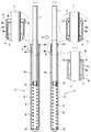
- (A) is the longitudinal cross-sectional view of the sheath heater which shows the state before swaging
- (b) is the longitudinal cross-sectional view of the sheath heater which shows the state after swaging
- (c) is an enlarged view which shows another embodiment. It shows the other form of a thick part, and is principal part sectional drawing of the sheath heater before swaging. It shows the other form of a thick part, and is principal part sectional drawing of the sheath heater before swaging. It is a longitudinal cross-sectional view of the glow plug which shows a prior art example.
- (A)-(c) is an expanded sectional view of the principal part regarding the modification of the enlarged diameter part of this invention.
- (A)-(c) is a principal part expanded sectional view which shows the related reference example.
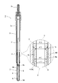
- a glow plug 1 shown in FIG. 1 is for preheating a diesel engine, and is formed by surrounding a sheath heater 2 in the radial direction with a cylindrical metal shell 3.
- the glow plug 1 is attached by screwing a male screw portion 3a formed on the metal shell 3 into a mounting hole (not shown) of the diesel engine, and a screw shaft 7a protruding from the rear end of the metal shell 3.
- a power cable (not shown) is connected to.
- the sheath heater 2 is made of a metal (for example, stainless alloy, nickel alloy, Inconel, etc.) sheath tube 4, a heating element 5 disposed in the sheath tube 4, and the inside of the sheath tube 4 around the heating element 5.
- the heating element 5 is a resistance coil, and has a distal end portion 5 f welded to the distal end of the sheath tube 4 and a rear end portion 5 r connected to the distal end of the lead 7.
- the sheath tube 4 has a cylindrical shape that extends in the axial direction and has a rear end opened and a through hole 4 b at the front end before the heating element 5 is welded. In the later state, as shown in FIGS. 6A and 6B, the through hole 4b is closed and the tip is closed. Moreover, the sheath tube 4 has the latching convex part 16 which protruded and deformed to radial direction inward in the seal part 4a, as shown in FIG.1, FIG.6 (b).
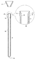
- the sheath tube 4 uses, for example, a disk-shaped metal material punched from an Inconel steel plate as a starting material, and a deep drawing process as shown in FIGS. 2 (a) to 2 (c) is performed as a precursor formation process. carry out.
- the plate material as the starting material is narrowed down to a small bowl shape having a bottomed cylindrical shape having a diameter larger than the depth as shown in FIG. 2A, and the depth as shown in FIG.
- the glass is squeezed into a cup shape having a bottomed cylindrical shape larger than the diameter, and further deeply squeezed into the shape of the sheath tube as shown in FIG.
- the enlarged diameter portion 11 is integrally formed at the rear end of the cup shape.
- the enlarged diameter portion 11 is formed in a tapered shape that gradually increases in diameter toward the rear.
- the through-hole 4b is provided in the front-end
- This through hole 4b forming step is performed simultaneously with the precursor forming step at the stage of FIG. 2C as in the embodiment, or separately after the precursor forming step of FIG. 2C. May be added.
- FIGS. 2 (a) to 2 (c) show an example of a part of the precursor formation process, and a plurality of processes are provided in the middle of each stage, and the process is gradually deepened. It is done. Further, in the precursor molding step, the diameter-enlarged portion 11 shown in FIG. 10 can be appropriately employed by appropriately increasing / decreasing the number of deep drawing processing steps or adding another plastic processing.
- the counterbore portion which is thinner than the main portion 4c occupying the longest region along the axial direction by expanding the inner diameter of the seal portion 4a at the rear end portion. Also referred to as “thin wall portion.”) 4d is formed, but the counterbore portion 4d can be formed by further adding a drawing process using a die and a punch after FIG. 2 (c).
- the precursor forming step may be completed in FIG.
- the work-in-process formed by the end of this precursor formation step corresponds to the “tube precursor” in the present invention.
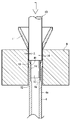
- the enlarged diameter portion 11 is separated and removed from the sheath tube 4 (tube precursor) with the enlarged diameter portion 11 formed in the precursor forming step in the shearing process of FIGS.
- the die 9 used in this shearing process has a shear hole 12 having an inner diameter of about 1.01d to 1.02d, which is slightly larger than the outer diameter d of the sheath tube 4, for example.
- the punch 10 has a tip convex shaft portion 13 entering the rear end of the sheath tube 4 and a shear shaft portion 14 following the tip convex shaft portion 13, and the outer diameter of the shear shaft portion 14 is the sheath. It is larger than the outer diameter d of the tube 4 and smaller than the shear hole 12, and an appropriate gap ⁇ (see FIG.
- the die 9 is the outer periphery of the sheath tube 4 and is disposed outside the radially expanded portion 11 in the radial direction.
- the punch 10 is disposed inside (inward) via the enlarged diameter portion 11 in order to shear the enlarged diameter portion 11 with the die 9.
- this outer diameter d refers to the outer diameter of the main part 4c in the sheath tube 4 with the enlarged diameter part 11 in a shearing process.
- the thickness of the entire seal portion 4a is increased.
- a thicker portion 4t can be formed.
- the rear end edge of the sheath tube 4 is drawn in a simple acute shape in order to express the shear in an easy-to-understand manner.
- the portion corresponding to the remaining portion 15 becomes a thick portion 4t that is thicker than the entire thickness of the seal portion 4a.
- the outer diameter of the shear hole 12 of the die 9, which is a processing jig to be used, the punch 10, and the adjustment of the gap ⁇ it is possible to manufacture so that the remaining portion 15 hardly remains. It is.
- the shape of the remaining portion 15 is slightly protruded in the radial direction accordingly. Yes.
- the sheath tube 4 of the present invention has the remaining part 15 of the enlarged diameter part 11 on the outer periphery of the counterbore part 4d as described above, and the part is a thick part 4t thicker than the entire counterbore part 4d,
- the thick portion 4t protrudes into the seal portion 4a as shown in FIG.
- the outer diameter of the portion (rear end side portion) of the seal member 8 that is exposed to the outside of the sheath tube 4 is ⁇ A (refer to the enlarged view of FIG.
- the diameter is ⁇ B and the outer diameter of the portion (tip side portion) fitted in the seal portion 4 a is ⁇ C, the relationship is ⁇ A> ⁇ B, ⁇ B ⁇ C. It is in a tight and tight state. Therefore, the sealing performance by the sealing member 8 is improved and there is almost no movement in the removal direction.
- the outer diameter of ⁇ B can be set to 45% to 95% when the larger one of ⁇ A and ⁇ C is 100%.
- the state of exceeding 95% means that the protruding amount of the locking projection 16 is very small, and the effect of suppressing the removal of the seal member 8 may not be obtained satisfactorily.
- it is less than 45% the sealing member 8 may be damaged, and sufficient airtightness may not be obtained.
- the outer diameter ⁇ A of the seal member 8 is the actual outer diameter of the seal member 8
- the ⁇ A, ⁇ B, and ⁇ C preferably satisfy ⁇ B ⁇ C ⁇ A.
- the seal member 8 fitted in the seal portion 4a elastically contracts and repels, and the repulsive force closely contacts the inner periphery of the seal portion 4a. Highly airtight.
- a portion (rear end side portion: outer diameter ⁇ A) of the seal member 8 that protrudes outside the sheath tube 4 does not exist. Also good.
- the difference ( ⁇ B ⁇ C) between the outer diameter ⁇ B and the outer diameter ⁇ C of the tip side portion at the position where the locking convex portion 16 is formed is 0.1 mm or more.
- a test was conducted to confirm the relationship between the difference ( ⁇ B ⁇ C) between the outer diameter ⁇ B at the formation position of the locking convex portion 16 and the outer diameter ⁇ C of the tip side portion and the airtightness.
- Seven types of sheath heaters (No. 1 to No. 7) having the same configuration as the sheath heater 2 shown in FIG. 6B and having a difference between ⁇ B and ⁇ C ( ⁇ B ⁇ C) were prepared. With these seven types of sheathed heaters placed in a thermostatic bath, after holding in an atmosphere at a temperature of 80 ° C. and a relative humidity of 90% for 30 minutes, holding in an atmosphere at a temperature of ⁇ 40 ° C. for 30 minutes within 120 minutes A cooling test was conducted with one cycle.
- the sheath heater was taken out of the thermostatic chamber every predetermined cycle of the cooling test, and an energization test was conducted in which the sheath heater was energized for 2 minutes at a voltage at which the sheath heater temperature was saturated between 900 ° C. and 1100 ° C. Then, the dimensions of each part of the sheath heater were measured using a micrometer before and after the energization test, and it was determined that the bulge occurred in the sheath heater when the bulge of 0.1 mm or more occurred.
- a sheath heater having a difference between ⁇ C and ⁇ B ( ⁇ C ⁇ B) of 0.1 mm or more ( ⁇ C ⁇ B ⁇ 0.1 mm) has an airtightness determination result of “A”, which is excellent It was confirmed that airtightness can be exhibited.
- the difference between ⁇ C and ⁇ B Is smaller than the value obtained by subtracting 1 mm from the difference between ⁇ C and ⁇ D (( ⁇ C ⁇ D) ⁇ 1 (unit: mm)) ( ⁇ C ⁇ B ⁇ ( ⁇ C ⁇ D) ⁇ 1 (unit: mm)).
- the swaging rate when swaging the sheath tube 4 (the cross-sectional area in the direction orthogonal to the axial direction of the sheath tube 4 after swaging relative to the cross-sectional area in the direction orthogonal to the axial direction of the sheath tube 4 before swaging) Is preferably set to 30% to 80%. By setting the swaging rate in this way, the excellent sealing performance of the seal member 8 can be exhibited in combination with the formation of the locking projections 16 on the sheath tube 4.
- the outer diameter of the seal portion 4a is formed to be substantially constant, the effect of improving the sealing property, the effect of improving the press-fit property, the effect of improving the ease of reducing the diameter, and the like are exhibited. .
- the sealing performance as a sheath heater is improved.
- the glow plug 1 is manufactured by press-fitting the sheath heater 2 manufactured as described above into the metal shell 3 and projecting the distal end side of the sheath tube 4 to the outside of the metal shell 3.
- the thick portion 4t is formed by leaving the remaining portion 15 in a projecting annular shape on the outer periphery of the rearmost end of the sheath tube 4, but the thick portion 4t is formed in the upper end of the seal portion 4a as shown in FIG. It may be formed radially inward on the circumference, or may be formed annularly on the intermediate outer circumference of the seal portion 4a as shown in FIG. Further, it may be formed in a shape that is discontinuous in the circumferential direction without being formed in an annular shape.
- the shape of the thick portion 4t can be variously modified without departing from the gist of the present invention, and the formation method is not limited to the deep drawing of the above embodiment, and the sheath tube 4 can be formed by upsetting. It may be formed by projecting the rear end portion outward or by cutting.
- the diameter reduction process of the seal part 4a is performed by a swaging machine.
- the caulking process having a caulking blade shorter than the axial length of the seal member 8 additionally or independently, and to form the locking convex portion 16 projecting radially inward.
- FIGS. 11A to 11C it is possible to obtain an effect of suppressing the movement of the seal member 8 in the removal direction (FIGS. 11A to 11C).
- a machining mark of the caulking blade remains on the outer peripheral surface of the seal portion 4a, so that it is not formed with a constant outer diameter.
Landscapes
- Engineering & Computer Science (AREA)
- Chemical & Material Sciences (AREA)
- Combustion & Propulsion (AREA)
- Mechanical Engineering (AREA)
- General Engineering & Computer Science (AREA)
- Resistance Heating (AREA)
Abstract
Priority Applications (3)
| Application Number | Priority Date | Filing Date | Title |
|---|---|---|---|
| US14/119,603 US9664388B2 (en) | 2011-05-25 | 2012-05-22 | Glow plug and method for manufacturing glow plug |
| JP2012538113A JP5503015B2 (ja) | 2011-05-25 | 2012-05-22 | グロープラグ及びそのグロープラグの製造方法 |
| EP12790308.6A EP2716975B1 (fr) | 2011-05-25 | 2012-05-22 | Bougie de préchauffage et procédé pour fabriquer une bougie de préchauffage |
Applications Claiming Priority (4)
| Application Number | Priority Date | Filing Date | Title |
|---|---|---|---|
| JP2011116832 | 2011-05-25 | ||
| JP2011-116831 | 2011-05-25 | ||
| JP2011-116832 | 2011-05-25 | ||
| JP2011116831 | 2011-05-25 |
Publications (1)
| Publication Number | Publication Date |
|---|---|
| WO2012160816A1 true WO2012160816A1 (fr) | 2012-11-29 |
Family
ID=47216907
Family Applications (1)
| Application Number | Title | Priority Date | Filing Date |
|---|---|---|---|
| PCT/JP2012/003350 Ceased WO2012160816A1 (fr) | 2011-05-25 | 2012-05-22 | Bougie à incandescence et procédé pour fabriquer une bougie à incandescence |
Country Status (4)
| Country | Link |
|---|---|
| US (1) | US9664388B2 (fr) |
| EP (1) | EP2716975B1 (fr) |
| JP (1) | JP5503015B2 (fr) |
| WO (1) | WO2012160816A1 (fr) |
Cited By (4)
| Publication number | Priority date | Publication date | Assignee | Title |
|---|---|---|---|---|
| JP2014169800A (ja) * | 2013-03-01 | 2014-09-18 | Ngk Spark Plug Co Ltd | グロープラグおよびその製造方法 |
| JP2014169799A (ja) * | 2013-03-01 | 2014-09-18 | Ngk Spark Plug Co Ltd | グロープラグおよびその製造方法 |
| JP2015141858A (ja) * | 2014-01-30 | 2015-08-03 | 京セラ株式会社 | ヒータ |
| JP2019184086A (ja) * | 2018-04-02 | 2019-10-24 | 日本特殊陶業株式会社 | ヒータの製造方法及びヒータ |
Families Citing this family (3)
| Publication number | Priority date | Publication date | Assignee | Title |
|---|---|---|---|---|
| DE102013104992A1 (de) * | 2013-05-15 | 2014-12-04 | Borgwarner Beru Systems Gmbh | Glühkerze |
| USD906383S1 (en) * | 2018-08-17 | 2020-12-29 | Hotset Gmbh | Electrical heater for injection-molding machine |
| CN119277578A (zh) * | 2024-11-07 | 2025-01-07 | 浙江绿储科技有限公司 | 一种电热管封口结构及封口方法 |
Citations (8)
| Publication number | Priority date | Publication date | Assignee | Title |
|---|---|---|---|---|
| US3252122A (en) * | 1962-09-28 | 1966-05-17 | Gen Electric | Sheathed electric heating unit |
| US3476916A (en) * | 1967-12-11 | 1969-11-04 | American Standard Inc | Electrical heater |
| JPS5465227A (en) * | 1977-10-15 | 1979-05-25 | Bosch Gmbh Robert | Cylindrical glow plug of internal combustion engine |
| JPH059698B2 (fr) * | 1983-04-08 | 1993-02-05 | Ueruman Saamaru Shisutemusu Corp | |
| JP2003133035A (ja) | 2001-10-26 | 2003-05-09 | Ngk Spark Plug Co Ltd | シーズ封入型電子機器の製造方法及びシーズ封入型電子機器の製造装置 |
| JP2009092291A (ja) * | 2007-10-05 | 2009-04-30 | Ngk Spark Plug Co Ltd | グロープラグおよびその製造方法 |
| JP2010159936A (ja) * | 2009-01-09 | 2010-07-22 | Ngk Spark Plug Co Ltd | シースヒータ用シースチューブの製造方法 |
| JP2010249354A (ja) * | 2009-04-13 | 2010-11-04 | Bosch Corp | ディーゼルエンジン用のメタルグロープラグのシース製造方法及びメタルグロープラグの製造方法、並びに、ディーゼルエンジン用のメタルグロープラグのシース及びディーゼルエンジン用のメタルグロープラグ |
Family Cites Families (5)
| Publication number | Priority date | Publication date | Assignee | Title |
|---|---|---|---|---|
| US3234633A (en) | 1962-09-28 | 1966-02-15 | Gen Electric | Method of making a sheathed electric heating unit |
| US4592134A (en) | 1983-04-08 | 1986-06-03 | Wellman Thermal Systems Corporation | Glow plug |
| US6064039A (en) * | 1998-04-15 | 2000-05-16 | Ngk Spark Plug Co., Ltd. | Glow plug with small-diameter sheath tube enclosing heating and control coils |
| JP5009698B2 (ja) | 2007-06-22 | 2012-08-22 | 花王株式会社 | 塗工紙の製造方法 |
| JP5170894B2 (ja) | 2009-01-15 | 2013-03-27 | 日本特殊陶業株式会社 | グロープラグ用のヒータチューブの製造方法及びグロープラグ |
-
2012
- 2012-05-22 WO PCT/JP2012/003350 patent/WO2012160816A1/fr not_active Ceased
- 2012-05-22 JP JP2012538113A patent/JP5503015B2/ja active Active
- 2012-05-22 US US14/119,603 patent/US9664388B2/en not_active Expired - Fee Related
- 2012-05-22 EP EP12790308.6A patent/EP2716975B1/fr active Active
Patent Citations (8)
| Publication number | Priority date | Publication date | Assignee | Title |
|---|---|---|---|---|
| US3252122A (en) * | 1962-09-28 | 1966-05-17 | Gen Electric | Sheathed electric heating unit |
| US3476916A (en) * | 1967-12-11 | 1969-11-04 | American Standard Inc | Electrical heater |
| JPS5465227A (en) * | 1977-10-15 | 1979-05-25 | Bosch Gmbh Robert | Cylindrical glow plug of internal combustion engine |
| JPH059698B2 (fr) * | 1983-04-08 | 1993-02-05 | Ueruman Saamaru Shisutemusu Corp | |
| JP2003133035A (ja) | 2001-10-26 | 2003-05-09 | Ngk Spark Plug Co Ltd | シーズ封入型電子機器の製造方法及びシーズ封入型電子機器の製造装置 |
| JP2009092291A (ja) * | 2007-10-05 | 2009-04-30 | Ngk Spark Plug Co Ltd | グロープラグおよびその製造方法 |
| JP2010159936A (ja) * | 2009-01-09 | 2010-07-22 | Ngk Spark Plug Co Ltd | シースヒータ用シースチューブの製造方法 |
| JP2010249354A (ja) * | 2009-04-13 | 2010-11-04 | Bosch Corp | ディーゼルエンジン用のメタルグロープラグのシース製造方法及びメタルグロープラグの製造方法、並びに、ディーゼルエンジン用のメタルグロープラグのシース及びディーゼルエンジン用のメタルグロープラグ |
Cited By (5)
| Publication number | Priority date | Publication date | Assignee | Title |
|---|---|---|---|---|
| JP2014169800A (ja) * | 2013-03-01 | 2014-09-18 | Ngk Spark Plug Co Ltd | グロープラグおよびその製造方法 |
| JP2014169799A (ja) * | 2013-03-01 | 2014-09-18 | Ngk Spark Plug Co Ltd | グロープラグおよびその製造方法 |
| JP2015141858A (ja) * | 2014-01-30 | 2015-08-03 | 京セラ株式会社 | ヒータ |
| JP2019184086A (ja) * | 2018-04-02 | 2019-10-24 | 日本特殊陶業株式会社 | ヒータの製造方法及びヒータ |
| JP7004456B2 (ja) | 2018-04-02 | 2022-01-21 | 日本特殊陶業株式会社 | ヒータの製造方法及びヒータ |
Also Published As
| Publication number | Publication date |
|---|---|
| EP2716975A4 (fr) | 2014-11-05 |
| EP2716975A1 (fr) | 2014-04-09 |
| US9664388B2 (en) | 2017-05-30 |
| JPWO2012160816A1 (ja) | 2014-07-31 |
| US20140090618A1 (en) | 2014-04-03 |
| EP2716975B1 (fr) | 2017-11-08 |
| JP5503015B2 (ja) | 2014-05-28 |
Similar Documents
| Publication | Publication Date | Title |
|---|---|---|
| JP5503015B2 (ja) | グロープラグ及びそのグロープラグの製造方法 | |
| EP2662623B1 (fr) | Bougie de préchauffage et son procédé de fabrication | |
| JP4897467B2 (ja) | グロープラグおよびその製造方法 | |
| JP2012063078A (ja) | グロープラグ及びその製造方法 | |
| JP2002367760A (ja) | ヒータ及びグロープラグ | |
| JP2011017478A (ja) | グロープラグ | |
| CN106716753A (zh) | 绝缘体以及火花塞 | |
| JP5352296B2 (ja) | シースヒータ及びグロープラグ並びにシースヒータの製造方法 | |
| JP5965179B2 (ja) | グロープラグ及びその製造方法 | |
| JP5329984B2 (ja) | シースヒータ用シースチューブの製造方法 | |
| JP4865375B2 (ja) | グロープラグ | |
| JP5965182B2 (ja) | グロープラグ及びその製造方法 | |
| JP5351236B2 (ja) | グロープラグ | |
| JP5965181B2 (ja) | グロープラグ及びその製造方法 | |
| JP2007032877A (ja) | グロープラグおよびその製造方法 | |
| JP5965180B2 (ja) | グロープラグ及びその製造方法 | |
| JP4960183B2 (ja) | グロープラグの製造方法 | |
| JP2008261577A (ja) | グロープラグ及びその製造方法 | |
| JP5639227B2 (ja) | グロープラグ | |
| JP6511315B2 (ja) | 複合部材の製造方法、およびグロープラグの製造方法 | |
| JP6101145B2 (ja) | ヒータモジュールの製造方法、および、グロープラグの製造方法 |
Legal Events
| Date | Code | Title | Description |
|---|---|---|---|
| ENP | Entry into the national phase |
Ref document number: 2012538113 Country of ref document: JP Kind code of ref document: A |
|
| 121 | Ep: the epo has been informed by wipo that ep was designated in this application |
Ref document number: 12790308 Country of ref document: EP Kind code of ref document: A1 |
|
| REEP | Request for entry into the european phase |
Ref document number: 2012790308 Country of ref document: EP |
|
| WWE | Wipo information: entry into national phase |
Ref document number: 14119603 Country of ref document: US |
|
| NENP | Non-entry into the national phase |
Ref country code: DE |