WO2012160822A1 - Électrode, son procédé de fabrication, dispositif énergétique la comprenant, matériel électronique et dispositif de transport - Google Patents
Électrode, son procédé de fabrication, dispositif énergétique la comprenant, matériel électronique et dispositif de transport Download PDFInfo
- Publication number
- WO2012160822A1 WO2012160822A1 PCT/JP2012/003391 JP2012003391W WO2012160822A1 WO 2012160822 A1 WO2012160822 A1 WO 2012160822A1 JP 2012003391 W JP2012003391 W JP 2012003391W WO 2012160822 A1 WO2012160822 A1 WO 2012160822A1
- Authority
- WO
- WIPO (PCT)
- Prior art keywords
- electrode
- group
- carbon
- conductive fiber
- current collector
- Prior art date
- Legal status (The legal status is an assumption and is not a legal conclusion. Google has not performed a legal analysis and makes no representation as to the accuracy of the status listed.)
- Ceased
Links
Images





Classifications
-
- H—ELECTRICITY
- H01—ELECTRIC ELEMENTS
- H01G—CAPACITORS; CAPACITORS, RECTIFIERS, DETECTORS, SWITCHING DEVICES, LIGHT-SENSITIVE OR TEMPERATURE-SENSITIVE DEVICES OF THE ELECTROLYTIC TYPE
- H01G11/00—Hybrid capacitors, i.e. capacitors having different positive and negative electrodes; Electric double-layer [EDL] capacitors; Processes for the manufacture thereof or of parts thereof
- H01G11/22—Electrodes
- H01G11/30—Electrodes characterised by their material
- H01G11/32—Carbon-based
- H01G11/36—Nanostructures, e.g. nanofibres, nanotubes or fullerenes
-
- H—ELECTRICITY
- H01—ELECTRIC ELEMENTS
- H01G—CAPACITORS; CAPACITORS, RECTIFIERS, DETECTORS, SWITCHING DEVICES, LIGHT-SENSITIVE OR TEMPERATURE-SENSITIVE DEVICES OF THE ELECTROLYTIC TYPE
- H01G11/00—Hybrid capacitors, i.e. capacitors having different positive and negative electrodes; Electric double-layer [EDL] capacitors; Processes for the manufacture thereof or of parts thereof
- H01G11/22—Electrodes
-
- H—ELECTRICITY
- H01—ELECTRIC ELEMENTS
- H01G—CAPACITORS; CAPACITORS, RECTIFIERS, DETECTORS, SWITCHING DEVICES, LIGHT-SENSITIVE OR TEMPERATURE-SENSITIVE DEVICES OF THE ELECTROLYTIC TYPE
- H01G11/00—Hybrid capacitors, i.e. capacitors having different positive and negative electrodes; Electric double-layer [EDL] capacitors; Processes for the manufacture thereof or of parts thereof
- H01G11/22—Electrodes
- H01G11/26—Electrodes characterised by their structure, e.g. multi-layered, porosity or surface features
- H01G11/28—Electrodes characterised by their structure, e.g. multi-layered, porosity or surface features arranged or disposed on a current collector; Layers or phases between electrodes and current collectors, e.g. adhesives
-
- H—ELECTRICITY
- H01—ELECTRIC ELEMENTS
- H01G—CAPACITORS; CAPACITORS, RECTIFIERS, DETECTORS, SWITCHING DEVICES, LIGHT-SENSITIVE OR TEMPERATURE-SENSITIVE DEVICES OF THE ELECTROLYTIC TYPE
- H01G11/00—Hybrid capacitors, i.e. capacitors having different positive and negative electrodes; Electric double-layer [EDL] capacitors; Processes for the manufacture thereof or of parts thereof
- H01G11/66—Current collectors
-
- H—ELECTRICITY
- H01—ELECTRIC ELEMENTS
- H01M—PROCESSES OR MEANS, e.g. BATTERIES, FOR THE DIRECT CONVERSION OF CHEMICAL ENERGY INTO ELECTRICAL ENERGY
- H01M4/00—Electrodes
- H01M4/02—Electrodes composed of, or comprising, active material
- H01M4/62—Selection of inactive substances as ingredients for active masses, e.g. binders, fillers
- H01M4/624—Electric conductive fillers
- H01M4/625—Carbon or graphite
-
- H—ELECTRICITY
- H01—ELECTRIC ELEMENTS
- H01M—PROCESSES OR MEANS, e.g. BATTERIES, FOR THE DIRECT CONVERSION OF CHEMICAL ENERGY INTO ELECTRICAL ENERGY
- H01M4/00—Electrodes
- H01M4/02—Electrodes composed of, or comprising, active material
- H01M4/64—Carriers or collectors
- H01M4/66—Selection of materials
- H01M4/663—Selection of materials containing carbon or carbonaceous materials as conductive part, e.g. graphite, carbon fibres
-
- H—ELECTRICITY
- H01—ELECTRIC ELEMENTS
- H01M—PROCESSES OR MEANS, e.g. BATTERIES, FOR THE DIRECT CONVERSION OF CHEMICAL ENERGY INTO ELECTRICAL ENERGY
- H01M4/00—Electrodes
- H01M4/02—Electrodes composed of, or comprising, active material
- H01M4/64—Carriers or collectors
- H01M4/66—Selection of materials
- H01M4/665—Composites
- H01M4/667—Composites in the form of layers, e.g. coatings
-
- B—PERFORMING OPERATIONS; TRANSPORTING
- B82—NANOTECHNOLOGY
- B82Y—SPECIFIC USES OR APPLICATIONS OF NANOSTRUCTURES; MEASUREMENT OR ANALYSIS OF NANOSTRUCTURES; MANUFACTURE OR TREATMENT OF NANOSTRUCTURES
- B82Y30/00—Nanotechnology for materials or surface science, e.g. nanocomposites
-
- H—ELECTRICITY
- H01—ELECTRIC ELEMENTS
- H01M—PROCESSES OR MEANS, e.g. BATTERIES, FOR THE DIRECT CONVERSION OF CHEMICAL ENERGY INTO ELECTRICAL ENERGY
- H01M10/00—Secondary cells; Manufacture thereof
- H01M10/05—Accumulators with non-aqueous electrolyte
- H01M10/052—Li-accumulators
- H01M10/0525—Rocking-chair batteries, i.e. batteries with lithium insertion or intercalation in both electrodes; Lithium-ion batteries
-
- Y—GENERAL TAGGING OF NEW TECHNOLOGICAL DEVELOPMENTS; GENERAL TAGGING OF CROSS-SECTIONAL TECHNOLOGIES SPANNING OVER SEVERAL SECTIONS OF THE IPC; TECHNICAL SUBJECTS COVERED BY FORMER USPC CROSS-REFERENCE ART COLLECTIONS [XRACs] AND DIGESTS
- Y02—TECHNOLOGIES OR APPLICATIONS FOR MITIGATION OR ADAPTATION AGAINST CLIMATE CHANGE
- Y02E—REDUCTION OF GREENHOUSE GAS [GHG] EMISSIONS, RELATED TO ENERGY GENERATION, TRANSMISSION OR DISTRIBUTION
- Y02E60/00—Enabling technologies; Technologies with a potential or indirect contribution to GHG emissions mitigation
- Y02E60/10—Energy storage using batteries
-
- Y—GENERAL TAGGING OF NEW TECHNOLOGICAL DEVELOPMENTS; GENERAL TAGGING OF CROSS-SECTIONAL TECHNOLOGIES SPANNING OVER SEVERAL SECTIONS OF THE IPC; TECHNICAL SUBJECTS COVERED BY FORMER USPC CROSS-REFERENCE ART COLLECTIONS [XRACs] AND DIGESTS
- Y02—TECHNOLOGIES OR APPLICATIONS FOR MITIGATION OR ADAPTATION AGAINST CLIMATE CHANGE
- Y02E—REDUCTION OF GREENHOUSE GAS [GHG] EMISSIONS, RELATED TO ENERGY GENERATION, TRANSMISSION OR DISTRIBUTION
- Y02E60/00—Enabling technologies; Technologies with a potential or indirect contribution to GHG emissions mitigation
- Y02E60/13—Energy storage using capacitors
-
- Y—GENERAL TAGGING OF NEW TECHNOLOGICAL DEVELOPMENTS; GENERAL TAGGING OF CROSS-SECTIONAL TECHNOLOGIES SPANNING OVER SEVERAL SECTIONS OF THE IPC; TECHNICAL SUBJECTS COVERED BY FORMER USPC CROSS-REFERENCE ART COLLECTIONS [XRACs] AND DIGESTS
- Y02—TECHNOLOGIES OR APPLICATIONS FOR MITIGATION OR ADAPTATION AGAINST CLIMATE CHANGE
- Y02T—CLIMATE CHANGE MITIGATION TECHNOLOGIES RELATED TO TRANSPORTATION
- Y02T10/00—Road transport of goods or passengers
- Y02T10/60—Other road transportation technologies with climate change mitigation effect
- Y02T10/70—Energy storage systems for electromobility, e.g. batteries
-
- Y—GENERAL TAGGING OF NEW TECHNOLOGICAL DEVELOPMENTS; GENERAL TAGGING OF CROSS-SECTIONAL TECHNOLOGIES SPANNING OVER SEVERAL SECTIONS OF THE IPC; TECHNICAL SUBJECTS COVERED BY FORMER USPC CROSS-REFERENCE ART COLLECTIONS [XRACs] AND DIGESTS
- Y10—TECHNICAL SUBJECTS COVERED BY FORMER USPC
- Y10S—TECHNICAL SUBJECTS COVERED BY FORMER USPC CROSS-REFERENCE ART COLLECTIONS [XRACs] AND DIGESTS
- Y10S977/00—Nanotechnology
- Y10S977/70—Nanostructure
- Y10S977/734—Fullerenes, i.e. graphene-based structures, such as nanohorns, nanococoons, nanoscrolls or fullerene-like structures, e.g. WS2 or MoS2 chalcogenide nanotubes, planar C3N4, etc.
- Y10S977/742—Carbon nanotubes, CNTs
- Y10S977/745—Carbon nanotubes, CNTs having a modified surface
- Y10S977/746—Modified with biological, organic, or hydrocarbon material
-
- Y—GENERAL TAGGING OF NEW TECHNOLOGICAL DEVELOPMENTS; GENERAL TAGGING OF CROSS-SECTIONAL TECHNOLOGIES SPANNING OVER SEVERAL SECTIONS OF THE IPC; TECHNICAL SUBJECTS COVERED BY FORMER USPC CROSS-REFERENCE ART COLLECTIONS [XRACs] AND DIGESTS
- Y10—TECHNICAL SUBJECTS COVERED BY FORMER USPC
- Y10S—TECHNICAL SUBJECTS COVERED BY FORMER USPC CROSS-REFERENCE ART COLLECTIONS [XRACs] AND DIGESTS
- Y10S977/00—Nanotechnology
- Y10S977/902—Specified use of nanostructure
- Y10S977/932—Specified use of nanostructure for electronic or optoelectronic application
- Y10S977/948—Energy storage/generating using nanostructure, e.g. fuel cell, battery
-
- Y—GENERAL TAGGING OF NEW TECHNOLOGICAL DEVELOPMENTS; GENERAL TAGGING OF CROSS-SECTIONAL TECHNOLOGIES SPANNING OVER SEVERAL SECTIONS OF THE IPC; TECHNICAL SUBJECTS COVERED BY FORMER USPC CROSS-REFERENCE ART COLLECTIONS [XRACs] AND DIGESTS
- Y10—TECHNICAL SUBJECTS COVERED BY FORMER USPC
- Y10T—TECHNICAL SUBJECTS COVERED BY FORMER US CLASSIFICATION
- Y10T156/00—Adhesive bonding and miscellaneous chemical manufacture
- Y10T156/10—Methods of surface bonding and/or assembly therefor
Definitions
- the present invention relates to an electrode including conductive fibers such as carbon nanotubes, a manufacturing method thereof, an energy device including the same, an electronic apparatus, and a transport device.
- nanowires such as nanowires, nanotubes, and nanohorns
- materials constituting the nanowires silver, silicon, gold, copper, zinc oxide, titanium oxide, gallium nitride, and the like have been studied.
- Carbon nanotubes are known as nanotubes
- carbon nanohorns are known as nanohorns.
- the most promising carbon nanotube as a conductive material has a structure in which a graphite sheet is rolled into a cylindrical shape.
- the material has a hollow structure having a diameter of about 0.7 to 100 nm and a length of several ⁇ m to several mm.
- the electrical properties of carbon nanotubes show semiconducting properties from metals depending on the diameter and chirality. Furthermore, since it does not have dangling bonds, it is chemically stable. It is also attracting attention as a material with low environmental impact because it consists of carbon atoms only.
- carbon nanotubes have the properties described above, they are expected to be applied as electron emission sources for flat panel displays, electrode materials for lithium batteries, electrode materials for electric double layer capacitors, and probe probes. .
- Carbon nanotubes can be synthesized by an arc discharge method using a carbon electrode, a benzene pyrolysis method, a laser deposition method, or the like.
- impurities such as graphite and carbon nanoparticles are synthesized together with the carbon nanotubes. Therefore, when the carbon nanotube is applied to the above-described electron emission source, battery electrode, probe probe, etc., it is necessary to remove impurities such as graphite and carbon nanoparticles in advance.
- carbon nanotubes of various lengths are synthesized in random directions, the characteristics as an electron emission source are limited.
- An electric double layer capacitor is a capacitor that uses an electric double layer generated between an electrode active material and an electrolytic solution, and has been used as a backup power source. Rapid growth is expected.
- the electrode active material of an electric double layer capacitor which activated carbon is used are widely known (e.g., see Patent Document 1) is, the carbon nanotube external surface area than the 2600 ⁇ 3000m 2 / g and the activated carbon
- the electric double layer capacitor using carbon nanotubes as an electrode active material has attracted attention because it is much larger and exhibits extremely tough mechanical properties and excellent electronic properties.
- the electric double layer capacitor has as much stored energy as possible. For this reason, methods for increasing the capacitor capacity by performing some kind of treatment on the electrode active material have been studied.
- Patent Document 2 two or more electrodes made of an active material powder, a conductive auxiliary agent (carbon powder), and an organic binder are disposed opposite to each other via a separator, and an aqueous electrolyte is injected between the electrode and the separator.
- a quinone compound is dissolved in the aqueous electrolyte solution.
- Patent Document 3 a carbon material / conductive polymer composite having a structure in which the surface of a carbon material (carbon black or activated carbon) having a high specific surface area is coated with a conductive polymer that causes a specific oxidation-reduction reaction, It is described that it is used for electrodes for power storage elements such as capacitors.
- Patent Document 4 is not related to an increase in capacitor capacity, but in a capacitor composition, in addition to carbon materials such as activated carbon, graphite, and conductive carbon, an organic dye derivative having a basic functional group, an anthraquinone derivative, and an acridone derivative Or a technique for achieving dispersion stabilization by blending a triazine derivative, an organic dye derivative having an acidic functional group, or a triazine derivative.
- Patent Document 5 describes a method of purifying carbon nanotubes by decomposing and removing impurities by irradiating ultraviolet light in an oxygen-containing atmosphere (air or oxygen atmosphere).
- Japanese Patent Publication No. 2-847 Japanese Patent Laid-Open No. 2002-1000039 JP 2003-109875 A JP 2010-62335 A JP 2004-345918 A
- Patent Documents 2 to 4 various materials are blended in a capacitor using carbon powder or the like as an electrode material to improve the capacitor characteristics.
- conductive fibers made of carbon such as carbon nanotubes are used. The use as an electrode active material is not described.
- Patent Document 5 is merely for the purpose of purifying carbon nanotubes, and is intended to irradiate ultraviolet light in a simple oxygen-containing atmosphere and does not introduce specific functional groups into carbon nanotubes. Absent.
- the present invention is an electrode containing conductive fibers made of carbon, such as carbon nanotubes, as an electrode active material, an electrode that exhibits high capacity when used in an energy device, a manufacturing method thereof, and the electrode It is an object to provide an energy device, an electronic device, and a transportation device.
- the present invention is an electrode including a current collector and a plurality of conductive fibers erected so that one end is electrically connected to the surface of the current collector, wherein the conductive fiber is carbon. And an electrode to which a functional group containing a carboxyl group is added.
- the present invention is an electrode including a current collector and a plurality of conductive fibers erected so that one end is electrically connected to the surface of the current collector, wherein the conductive fiber is carbon. And an electrode having a functional group containing an oxo group and a functional group containing a hydroxy group.
- a quinone group-containing compound is supported on the conductive fiber.
- the present invention is also a method for producing the electrode, the step of adding a carboxyl group to a conductive fiber made of carbon that is erected so that one end is electrically connected to the surface of the current collector. It is also a method including.
- the present invention is also a method for producing the electrode, wherein the functional group containing an oxo group with respect to the conductive fiber made of carbon is provided so that one end thereof is electrically connected to the surface of the current collector. And adding a functional group containing a hydroxy group.
- the method for producing an electrode of the present invention preferably further includes a step of supporting a quinone group-containing compound on the conductive fiber.
- the present invention includes a positive electrode, a separator, and a negative electrode laminated in this order, at least one of the positive electrode and the negative electrode is the electrode, and a space between the positive electrode and the negative electrode is filled with an electrolyte solution. It is also an energy device.
- the present invention is an electronic device that includes the energy device and an electric circuit, and is supplied with current from the energy device to the electric circuit, and further includes the energy device and a drive unit. It is also a transport device in which current is supplied to the drive unit.
- an energy device having a higher capacity can be provided.
- Electrode 1 an electrode including a conductive fiber to which a functional group is added and a manufacturing method thereof will be described.
- the electrode of the present embodiment includes a current collector and a plurality of conductive fibers erected on the surface of the current collector. One end of the conductive fiber is electrically connected to the surface of the current collector, but the other end is not connected to the surface.
- the current collector is a plate-like material formed from a conductive material.
- the conductive material include, but are not limited to, silicon, stainless steel, iron, aluminum, nickel, titanium, copper, and the like.
- aluminum is used as a current collector of an electric double layer capacitor using activated carbon as an electrode active material, and can be particularly preferably used in the present invention. This is because aluminum forms a thin passive film on the surface, so that aluminum does not melt even when a high voltage is applied.
- the conductive fiber used in the present invention is a cylindrical hollow member made of carbon.
- the diameter is preferably 0.1 to 100 nm.
- the conductive fibers can be erected at high density on the current collector, and an electrode with high energy density can be configured.
- Examples of conductive fibers made of carbon include, but are not limited to, carbon nanotubes, carbon nanohorns, activated carbon fibers, and the like. Carbon nanotubes are preferred because of the ease of orientation synthesis.
- nanowires made of metal such as silver, gold, copper, silicon, zinc oxide, titanium oxide, or gallium nitride are known. It is considered that the same effect as that of the present invention can be achieved by adding a group.
- Carbon nanotubes are extremely fine tube (tube) -like substances having a hole diameter of nanometers and formed by bonding carbon atoms in a network.
- the carbon nanotubes used in the present embodiment may be single-walled carbon nanotubes or multi-walled carbon nanotubes.
- Multi-walled carbon nanotubes consist of a plurality of concentric carbon tubes with different diameters. In the present invention, it is preferable to use multi-walled carbon nanotubes. When multi-walled carbon nanotubes are used, the shape of the carbon nanotubes is easily maintained during the introduction of functional groups described later, and the physical properties of the electrode are unlikely to deteriorate. Multi-walled carbon nanotubes are preferable for electrode applications because they are excellent in conductivity.
- the diameter of the carbon nanotube is not particularly limited, but when used for an electrode of an electric double layer capacitor or a lithium ion secondary battery, lithium ions having an ion radius of 0.074 nm and electrolyte ions having an ion radius of about 0.5 nm are used. Since it is assumed to enter the inside, the range of 0.1 nm to 10 nm is preferable, and the range of 0.1 nm to 3 nm is more preferable.
- the distance between the carbon nanotubes is preferably short. However, it is desirable that the distance between the carbon nanotubes is sufficient for the electrolyte ions in the electrolytic solution to move.
- the carbon nanotubes are preferably erected on the surface of the current collector through the catalyst metal particles. That is, one end of the carbon nanotube is in contact with one of the catalyst metal particles dispersed and arranged on the current collector surface.
- the carbon nanotubes are synthesized so as to stand on the surface of the current collector through the catalyst metal particles.
- a carboxyl group (—COOH) is added as a functional group including a carboxyl group to the outer surface of the conductive fiber as a functional group.
- the carbon atoms constituting the conductive fiber and the carbon atoms in the carboxyl group are chemically bonded.
- the capacity of the energy device including the electrode of this embodiment is remarkably improved.
- one carboxyl group may be added to one carbon nanotube, or a plurality of carboxyl groups may be added.
- the content of the functional group in the electrode of the present embodiment is not particularly limited and can be appropriately determined according to a desired electrode capacity.
- the amount of carbon constituting the conductive fiber (however, included in the functional group)
- the weight ratio with respect to 1 is preferably 0.19 or more and 0.56 or less, excluding the mass of carbon.
- the content can be calculated from the intensity ratio of a peak indicating carbon constituting the carbon nanotube and a peak indicating carbon constituting the carboxyl group by XPS.
- the manufacturing method includes a step of preparing a current collector having a plurality of conductive fibers erected so that one end is electrically connected to the surface, and a step of adding a carboxyl group to the conductive fibers; ,including.
- a method for standing conductive fibers on the current collector surface will be described.
- Various types of conductive fibers can be used as described above.
- a method of standing a plurality of carbon nanotubes on the surface of the current collector will be described in the case where the conductive fibers are carbon nanotubes.
- Carbon nanotubes can be formed by a transfer method. However, from the viewpoint of obtaining carbon nanotubes with good orientation, a method of growing carbon nanotubes directly on a current collector (direct synthesis method) is preferable. In this method, carbon nanotubes are synthesized starting from catalytic metal particles attached to the surface of the current collector.
- Examples of the material constituting the catalyst metal particles include metals such as nickel, iron, cobalt, zinc, molybdenum, gold, silver, and copper; alloys containing two or more of these metals; oxides or carbides of these metals. However, it can be appropriately selected depending on the desired carbon nanotube diameter and its synthesis method.
- the catalyst metal particles on the surface of the current collector are enlarged by heating at the time of carbon nanotube synthesis or preheating before synthesis. It is said that there is a correlation between the catalyst metal particle diameter and the synthesized carbon nanotube diameter. Therefore, when a carbon nanotube diameter of 1 to 100 nm is desired, the catalyst metal particle diameter is desirably adjusted to 1 to 100 nm.
- a vapor phase chemical vapor deposition (CVD) method As a method of directly synthesizing the standing carbon nanotubes on the current collector, a vapor phase chemical vapor deposition (CVD) method, a laser ablation method, an arc discharge, an in-solution electrolytic synthesis method, or the like can be used.
- the method is preferred.
- CVD methods There are two main types of CVD methods: a thermal CVD method that thermally decomposes a source gas and a plasma CVD method that decomposes a source gas with plasma.
- Carbon nanotubes can be synthesized by a CVD method at a temperature of 550 ° C. to 750 ° C. and a pressure of 200 Pa.
- a hydrocarbon gas such as methane, ethylene or acetylene, or an alcohol such as methanol is introduced into the chamber as a carbon source, and the carbon is placed on a current collector on which catalyst metal particles are arranged on the surface.
- a gas such as argon, nitrogen, or hydrogen may be used as a carrier gas for the carbon source.
- the carbon nanotube synthesis time is adjusted according to the length of the target carbon nanotube. Since the growth rate varies depending on the synthesis temperature, gas pressure, and the type of carbon source used, the synthesis time cannot be generally described. However, in the range of the above conditions, for example, in order to synthesize carbon nanotubes having a length of 100 ⁇ m, the synthesis time Can be about 10 minutes to 4 hours.
- a carboxyl group is added to the conductive fibers erected on the current collector surface. Addition of a carboxyl group to the conductive fiber is possible by immersing the conductive fiber in nitric acid. However, in this method, there is a possibility that the acid corrodes the current collector or the catalyst, or the conductive fibers are peeled off from the current collector. Therefore, it is preferable to add a carboxyl group to the conductive fiber by oxidizing a part of the conductive fiber made of carbon by irradiating the conductive fiber with ultraviolet rays in an ozone-containing atmosphere. For ultraviolet irradiation, for example, a low-pressure mercury lamp can be used.
- Intensity of ultraviolet irradiation may be, for example, 3 mW / cm 2 or more 20 mW / cm 2 or less.
- the current collector is preferably heated. This is because the carboxyl group addition reaction may be promoted.
- a carboxyl group is not introduce
- the electrode of this embodiment obtained as described above can be used as it is as an electrode included in the energy device, and can also be used as the electrode of Embodiment 2 by supporting a quinone group-containing compound.
- Electrode 2 an electrode including a conductive fiber to which a functional group including a carboxyl group is added, and a quinone group-containing compound supported on the conductive fiber, and a method for manufacturing the electrode will be described.
- the electrode of this embodiment is the same as the electrode of Embodiment 1 except that the quinone group-containing compound is supported on conductive fibers. Explanation of the same points is omitted.
- the capacity of the energy device can be improved synergistically with the added carboxyl group by supporting the quinone group-containing compound on the conductive fiber.
- the carrying means that the quinone group-containing compound is physically or chemically bonded or adsorbed to the conductive fiber.
- the quinone group-containing compound interacts with an electrolyte component having a cation. As a result, since more cations are attracted to the electrode carrying the quinone group-containing compound, the capacity of the negative electrode is particularly greatly increased.
- the quinone group-containing compound is present on the surface of the current collector on which the conductive fiber to which a functional group containing a carboxyl group is added is erected.
- a functional group containing a carboxyl group is added and in addition to a carbon nanotube carrying a quinone group-containing compound, a functional group containing a carboxyl group is added.
- a carbon nanotube that is not supported a carbon nanotube that is supported by a quinone group-containing compound but has no carboxyl group-containing functional group, or a carbon nanotube that has neither a carboxyl group-containing functional group nor a quinone group-containing compound. May also be present.
- the quinone group-containing compound is not particularly limited.
- the quinone group-containing compound has a large effect of improving the capacity of the energy device, it is preferably a compound having no amino group.
- the quinone group-containing compound is preferably not a polymer but a monomer. This is because, when the conductive fiber described later is compressed after supporting the quinone group-containing compound, the compression becomes difficult if the quinone group-containing compound is a polymer.
- the monomer means a low molecular weight compound that does not contain a repeating structure as contained in a polymer.
- the amount of the quinone group-containing compound supported on the conductive fiber is not particularly limited. However, in this embodiment, since the conductive fiber has a carboxyl group, more quinone group-containing compounds can be supported. This allows the conductive fiber to carry a larger amount of the quinone group-containing compound as compared with the case where the carboxyl group does not have a carboxyl group by the interaction of the carboxyl group with the quinone group-containing compound. As a result, the capacity can be greatly improved by the synergistic action of the carboxyl group and the quinone group-containing compound.
- the manufacturing method includes a step of preparing a current collector having a plurality of conductive fibers erected so that one end is electrically connected to the surface, and a functional group containing a carboxyl group with respect to the conductive fibers. And a step of supporting a quinone group-containing compound on the conductive fiber to which the functional group including the carboxyl group has been added. Description of the steps already described for the first embodiment is omitted.
- the step of supporting the quinone group-containing compound on the conductive fiber is performed by bringing the liquid containing the quinone group-containing compound into contact with the conductive fiber to which a functional group containing a carboxyl group is added, which is erected on the current collector surface.
- a quinone group-containing compound is dissolved or dispersed in a solvent or dispersion medium to obtain a solution or dispersion of the quinone group-containing compound, and then the conductive fiber is brought into contact with the solution or dispersion.
- the contact can be performed by immersing the current collector in the solution or dispersion, or by applying or spraying the solution or dispersion on the surface of the current collector. It is preferable to remove the solvent or the dispersion medium by drying after the contact.
- the solvent for dissolving or dispersing the quinone group-containing compound may be appropriately selected from those suitable for dissolving or dispersing the compound to be used, and is not particularly limited. Examples include water and organic solvents such as ethanol, acetone, chloroform, propylene carbonate, and tetrahydrofuran.
- a procedure in which a functional group containing a carboxyl group is added to the conductive fiber after the quinone group-containing compound is supported on the conductive fiber on the surface of the current collector may be considered.
- the supported quinone group-containing compound is oxidized and further decomposed at the time of adding the carboxyl group, the desired effect may not be achieved. Therefore, it is preferable to support the quinone group-containing compound after adding the carboxyl group. .
- FIG. 1A is a conceptual diagram of the electric double layer capacitor of the present embodiment.
- the electric double layer capacitor 10 includes a separator 15 and a positive electrode 16 and a negative electrode 17 that are disposed to face each other with the separator 15 interposed therebetween.
- the positive electrode 16 includes a current collector 11 and a plurality of conductive fibers 12 provided upright on the current collector 11.
- the negative electrode 17 includes a current collector 13 and a plurality of conductive fibers 14 erected on the current collector 13.
- the separator 15 is in contact with the conductive fiber 12 on one side and in contact with the conductive fiber 14 on the other side.
- the electrode according to Embodiment 1 or Embodiment 2 can be used. In particular, since the electrode of the present invention can attract cations, it is preferably used as the negative electrode 17.
- the separator 15 is a material that separates both electrodes by being disposed between the positive electrode and the negative electrode, and retains the electrolytic solution to ensure ion conductivity between the positive electrode and the negative electrode.
- Examples of the material constituting the separator include cellulose, polypropylene, polytetrafluoroethylene, and the like, but are not particularly limited.
- the space between the positive electrode and the negative electrode is filled with an electrolytic solution, and the electrolytic solution is held by a separator.
- the electrolytic solution one composed of a solvent and an electrolyte can be used.
- the solvent of the electrolytic solution is not particularly limited.
- the electrolyte of the electrolytic solution is not particularly limited, but for example, selected from tetraethylammonium tetrafluoroborate, triethylmethylammonium tetrafluoroborate, triethylmethylammonium bis, tetraethylammonium hexafluorophosphate, and tetraethylammonium bis One or more combinations can be used.
- an ionic liquid imidazolium-based, pyridinium-based, aliphatic-based, pyrrolidinium-based, ammonium-based, phosphonium-based, or sulfonium-based compound or a combination of a plurality of compounds should be used. You can also.
- the capacity per unit volume (F / cm 3 ) is proportional to the density of the active material. Therefore, in an electrode in which the active material is made of conductive fibers, it is considered that the density and the capacity are proportional as long as the surface area of the active material does not change. Therefore, it is considered that increasing the density of the active material increases the energy per unit volume (energy density).
- the maximum density of the conductive fiber layer achieved by synthesis is not necessarily the ideal maximum density as the active material layer (per unit volume for ion adsorption / desorption). It is not always the density that maximizes the surface area of In order to approach the ideal maximum density, in the present invention, by compressing in a state where the separator is laminated on the conductive fiber layer, the density of the conductive fiber layer is increased, and the electrode and the separator are pressure-bonded, It may be integrated. Accordingly, the density of the conductive fiber layer can be increased without causing problems such as peeling of the conductive fiber layer, and the energy density of the electric double layer capacitor can be improved. Moreover, since the electrode and the separator are integrated, handling is easy when they are stored in a container.
- two electrode plates (a positive electrode and a negative electrode) and a separator are prepared. Any one of the two electrode plates may be the electrode of the present invention, and the other electrode plate may be another electrode as conventionally known.
- the covering step the surface of the electrode plate (the surface on the side where the electrode active material is present) is covered with a separator to form a laminate composed of the electrode plate and the separator.
- An energy storage device can be manufactured by impregnating the laminate obtained as described above with an electrolytic solution and finally storing it in a container.
- the coating step can be performed after impregnating the separator or the electrode plate with the electrolytic solution.
- the wound energy device is shown, but the present invention is not limited to this.
- the energy device according to the embodiment of the present invention may be of a stacked type including electrode members stacked without winding.
- the electrode of the present invention is an energy storage device such as an electrochemical capacitor, a lithium ion capacitor, a lithium ion secondary battery, an organic battery, a metal oxide, or a pseudocapacitor capacitor using a conductive polymer. It can be applied as an electrode in general.
- at least one of the electrodes included in the energy storage device may be the electrode of the present invention.
- the electrode of the present invention for both positive and negative electrodes.
- lithium metal oxides such as lithium cobaltate, silicon compounds, or lithium metals are usually used as the positive electrode active material, and graphite or the like is used as the negative electrode active material.
- the electrode of the present invention can be used instead of the electrode containing graphite.
- the positive electrode it is possible to use conductive fibers as the active material support material. That is, the electrode of the present invention carrying the above-described positive electrode active material can be used as the positive electrode.
- the electrode of the present invention can be used as either one or both of the positive and negative electrodes.
- the electrode of the present invention carrying an active material can be used as at least one of positive and negative electrodes.
- the conductive fiber included in the electrode of the present invention may function as an electrode active material, or may function as a support material for other electrode active materials. It may be a thing.
- the energy device according to the present embodiment is mounted on a portable device having a wireless communication function typified by a mobile phone, an electronic device such as an information processing terminal typified by a notebook computer, or a transport device typified by a hybrid vehicle. be able to.
- FIG. 7 is a conceptual diagram showing an example of an electronic apparatus equipped with the energy device according to this embodiment.
- the electronic device 20 includes an energy device and an electric circuit, and current is supplied from the energy device to the electric circuit.
- the electronic device 20 is, for example, a mobile phone.
- the electric circuit is, for example, an LED flash.
- FIG. 8 is a conceptual diagram showing an example of a transportation device equipped with the energy device according to the present embodiment.
- the transport device 30 includes an energy device and a drive unit, and current is supplied from the energy device to the drive unit.
- the transport device 30 is, for example, an electric vehicle.
- the drive unit is, for example, an electric motor.
- Example 1 an electrode in which a carboxyl group was added to the conductive fiber standing on the surface of the current collector was produced. Carbon nanotubes were used as the conductive fibers.
- the current collector was set in an EB vapor deposition machine, and Al was deposited as a catalyst material in a layer thickness of 0.5 nm, and further Fe was deposited in a thickness of 1 nm.
- the degree of vacuum before vapor deposition was 1.2E ⁇ 5 Pa.
- the deposition rate of Al and Fe was 1 nm / s.
- the current collector was heat-treated at 300 ° C. for 30 minutes in a vacuum to form catalytic metal particles on the current collector surface.
- carbon nanotubes were synthesized.
- Plasma CVD was used for the synthesis of carbon nanotubes.
- CH 4 was used as a reaction gas and hydrogen was used as a carrier gas.
- a current collector having catalytic metal particles on the surface was set in the chamber, and evacuation was performed using a rotary pump and a turbo molecular pump. The ultimate vacuum was 5E -4 Pa.
- CH 4 and hydrogen were allowed to flow into the chamber. The flow rates were 25 sccm and 40 sccm, respectively.
- the microwave output was 80 W.
- the reaction temperature was 645 ° C. and synthesis was performed for 70 minutes.
- carbon nanotubes having an average length of 150 ⁇ m standing on the surface of the current collector were synthesized.
- TEM transmission electron microscope
- the surface of the current collector after the synthesis of carbon nanotubes was irradiated with ultraviolet rays in an ozone atmosphere to add carboxyl groups to the carbon nanotubes.
- a low-pressure mercury lamp was used for ultraviolet irradiation.
- Ozone was generated in the chamber while flowing oxygen at a flow rate of 100 ml / min through a chamber having a volume of 1250 cm 3 .
- the influence on the carbon nanotube can be suppressed by setting the flow rate of oxygen to 120 ml / min or less.
- a carboxyl group addition reaction can fully be accelerated
- the current collector was heated to 110 ° C.
- the ultraviolet irradiation time was changed in the range of 5 to 60 minutes.
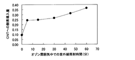
- FIG. 2 shows the measurement results of the amount of oxygen introduced into the carbon nanotubes (O1s / C1s intensity ratio) with respect to the ultraviolet irradiation time in an ozone atmosphere. It can be seen that the oxygen introduction amount increases as the ultraviolet irradiation time increases.
- a carboxyl group as a functional group added to a conductive fiber such as a carbon nanotube, but the present invention is not limited to this.
- a peak indicating a double bond between a carbon atom and an oxygen atom and a peak indicating a single bond between a carbon atom and an oxygen atom are detected.
- the functional group added to the conductive fiber has both a functional group containing an oxo group ( ⁇ O) and a functional group containing a hydroxy group (—OH).
- the relationship between the amount of the functional group and the capacity is the same as that of the conductive fiber having a functional group containing a carboxyl group. It is done.
- the conductive fiber to which both the functional group containing an oxo group and the functional group containing a hydroxy group are added can be produced in the same manner as the conductive fiber to which a functional group containing a carboxyl group is added.
- Comparative Example 1 an electrode was produced by carrying a quinone group-containing compound on conductive fibers standing on the surface of a current collector, and the electric double layer capacitor characteristics were measured. Carbon nanotubes were used as the conductive fibers. Naphthoquinone was used as the quinone group-containing compound.
- the method for producing the carbon nanotubes standing on the surface of the current collector is the same as in Example 1. Next, naphthoquinone was supported on the carbon nanotube.
- naphthoquinone was dissolved in acetone until saturated. Carbon nanotubes standing on the surface of the current collector were immersed in this solution for 6 hours. After pulling up, the current collector surface was washed with acetone. As a result, naphthoquinone was supported on the carbon nanotube.
- the capacitance as an electric double layer capacitor was measured.
- the measurement was performed by a three-electrode system using an Ag / Ag + type reference electrode.
- As the electrolytic solution a solution obtained by dissolving tetraethylammonium tetrafluoroborate in propylene carbonate was used. The concentration of tetraethylammonium tetrafluoroborate was 0.7 mol / l.
- the electrode which is a current collector after acetone washing, was immersed in the electrolytic solution, and then the pressure was reduced to such an extent that the electrolytic solution did not boil, so that the electrolytic solution penetrated into the details of the electrode active material.
- Example 2 In this example, a carboxyl group was added to the conductive fiber standing on the surface of the current collector, and an electrode was manufactured by supporting a quinone group-containing compound, and the electric double layer capacitor characteristics were measured. Carbon nanotubes were used as the conductive fibers. Naphthoquinone was used as the quinone group-containing compound.
- the method for producing the carbon nanotube standing on the surface of the current collector and the method for adding the carboxyl group are the same as in Example 1.
- the number of carboxyl groups added to one carbon six-membered ring constituting the carbon nanotube was changed in the range of 0 to 0.675 by changing the ultraviolet irradiation time.
- the method for supporting the quinone group-containing compound on the carbon nanotubes is the same as in Comparative Example 1.
- FIG. 4 shows the result of measuring the capacitor capacity when the electrode of this example is used by the method described in Comparative Example 1.
- FIG. 4 also shows the results of measuring the capacitor capacity when using the electrode of Example 1 (carboxyl group added but not quinone group-containing compound supported).
- the capacitor capacity on the vertical axis is shown as a relative ratio to the capacitor capacity when no carboxyl group is added.
- Example 1 that did not carry naphthoquinone, the maximum value of the increase in capacity was 1.9 times, whereas in Example 2 that supported naphthoquinone, the maximum value of the increase in capacity was 3.3 times. From this result, it can be seen that when a carboxyl group is present, the capacitance of the capacitor is greatly increased by further supporting naphthoquinone.
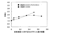
- Example 3 This example is the same as Example 2 except that 1,4-diaminoanthraquinone was used as the quinone group-containing compound.
- FIG. 5 also shows the measurement results of Example 1.
- the effect of increasing the capacity by supporting 1,4-diaminoanthraquinone was observed.
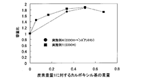
- Example 4 In this example, benzanthrone (a compound having only one oxygen double bond in the benzene ring) was used as a material having one oxygen double bond in the benzene ring instead of the quinone group-containing compound. Except this point, the second embodiment is the same as the second embodiment.
- FIG. 6 also shows the measurement results of Example 1.
- the increase in capacity is suppressed as compared with the first embodiment. From this result, it was found that when a compound having only one oxygen double bond was supported on a benzene ring instead of a quinone group-containing compound, the capacity increasing effect due to carboxyl group addition was inhibited.
- the energy device using the electrode according to the present invention has a high capacity and can improve the energy density, the energy of a mobile terminal device such as a mobile phone or a portable computer, or a mobile device such as an automobile, a bicycle, or a train. Useful as a source.
Landscapes
- Engineering & Computer Science (AREA)
- Power Engineering (AREA)
- Chemical & Material Sciences (AREA)
- Microelectronics & Electronic Packaging (AREA)
- Materials Engineering (AREA)
- Chemical Kinetics & Catalysis (AREA)
- Electrochemistry (AREA)
- General Chemical & Material Sciences (AREA)
- Nanotechnology (AREA)
- Crystallography & Structural Chemistry (AREA)
- Composite Materials (AREA)
- Electric Double-Layer Capacitors Or The Like (AREA)
- Battery Electrode And Active Subsutance (AREA)
- Cell Electrode Carriers And Collectors (AREA)
Abstract
Priority Applications (3)
| Application Number | Priority Date | Filing Date | Title |
|---|---|---|---|
| JP2013516217A JP6004198B2 (ja) | 2011-05-25 | 2012-05-24 | 電極、その製造方法、それを含むエネルギーデバイス、電子機器および輸送デバイス |
| CN201280021151.4A CN103503100B (zh) | 2011-05-25 | 2012-05-24 | 电极、其制造方法、含有其的能量器件、电子设备和输送设备 |
| US14/118,154 US9269504B2 (en) | 2011-05-25 | 2012-05-24 | Electrode, method for producing electrode, and energy device, electronic device, and transportation device including electrode |
Applications Claiming Priority (2)
| Application Number | Priority Date | Filing Date | Title |
|---|---|---|---|
| JP2011-116629 | 2011-05-25 | ||
| JP2011116629 | 2011-05-25 |
Publications (1)
| Publication Number | Publication Date |
|---|---|
| WO2012160822A1 true WO2012160822A1 (fr) | 2012-11-29 |
Family
ID=47216912
Family Applications (1)
| Application Number | Title | Priority Date | Filing Date |
|---|---|---|---|
| PCT/JP2012/003391 Ceased WO2012160822A1 (fr) | 2011-05-25 | 2012-05-24 | Électrode, son procédé de fabrication, dispositif énergétique la comprenant, matériel électronique et dispositif de transport |
Country Status (4)
| Country | Link |
|---|---|
| US (1) | US9269504B2 (fr) |
| JP (1) | JP6004198B2 (fr) |
| CN (1) | CN103503100B (fr) |
| WO (1) | WO2012160822A1 (fr) |
Cited By (8)
| Publication number | Priority date | Publication date | Assignee | Title |
|---|---|---|---|---|
| CN105247639A (zh) * | 2013-03-28 | 2016-01-13 | 国立大学法人东北大学 | 蓄电装置及其电极材料 |
| KR20160144756A (ko) * | 2015-06-09 | 2016-12-19 | 주식회사 엘지화학 | 리튬 황 전지 및 이의 제조 방법 |
| JP2017073267A (ja) * | 2015-10-07 | 2017-04-13 | セイコーエプソン株式会社 | 電池用電極、電池用電極の製造方法、電池 |
| KR101738273B1 (ko) * | 2015-11-18 | 2017-05-23 | 포항공과대학교 산학협력단 | 리튬 유기 전지 및 그 제조 방법 |
| JP2018521495A (ja) * | 2015-10-15 | 2018-08-02 | エルジー・ケム・リミテッド | 負極活物質及びこれを含む二次電池 |
| JP2021527295A (ja) * | 2018-05-22 | 2021-10-11 | モレキュラー レバー デザイン,エルエルシー | 高表面積ナノチューブを使用する向上したリチウムイオン電池 |
| WO2023148868A1 (fr) * | 2022-02-03 | 2023-08-10 | スペースリンク株式会社 | Pâte d'électrode, électrode, dispositif de stockage d'énergie et procédé de fabrication |
| JP2023546283A (ja) * | 2020-10-15 | 2023-11-01 | ユニバーシティ オブ サウス-イースタン ノルウェー | スーパーキャパシタ用途向けの微細構造を有する金属基板上での架橋型カーボンナノチューブの直接成長 |
Families Citing this family (6)
| Publication number | Priority date | Publication date | Assignee | Title |
|---|---|---|---|---|
| US9099241B1 (en) * | 2013-04-10 | 2015-08-04 | Mainstream Engineering Corporation | Enhanced charge-storage electrochemical double layer capacitors with nanoscale electrolyte confinement tunability, and a method for production thereof to obtain axi-symmetric, high surface area electrode growth |
| JP2013243205A (ja) * | 2012-05-18 | 2013-12-05 | Seiko Instruments Inc | 電気化学セル |
| KR20140075836A (ko) * | 2012-11-27 | 2014-06-20 | 삼성전기주식회사 | 전극 구조체 및 그 제조 방법, 그리고 상기 전극 구조체를 구비하는 에너지 저장 장치 |
| CN107978732B (zh) * | 2014-06-20 | 2020-03-27 | 东莞新能源科技有限公司 | 极片及电池 |
| KR102385549B1 (ko) * | 2017-08-16 | 2022-04-12 | 삼성전자주식회사 | 반도체 패키지 및 반도체 패키지의 제조 방법 |
| US20240352607A1 (en) * | 2021-12-27 | 2024-10-24 | Electric Hydrogen Co. | Multilayer coatings on porous transport layers |
Citations (5)
| Publication number | Priority date | Publication date | Assignee | Title |
|---|---|---|---|---|
| JP2004535349A (ja) * | 2001-05-18 | 2004-11-25 | ハイピリオン カタリシス インターナショナル インコーポレイテッド | 過酸素化合物で酸化する事に依るカーボンナノチューブの改質 |
| JP2005050669A (ja) * | 2003-07-28 | 2005-02-24 | Tdk Corp | 電極、及び、それを用いた電気化学素子 |
| JP2006222175A (ja) * | 2005-02-09 | 2006-08-24 | Sumitomo Metal Mining Co Ltd | 電気2重層キャパシタ電極の製造方法、得られる電気2重層キャパシタ電極、及びそれを用いた電気2重層キャパシタ |
| JP2008517863A (ja) * | 2004-10-22 | 2008-05-29 | ハイピリオン カタリシス インターナショナル インコーポレイテッド | カーボンナノチューブの改善されたオゾン分解 |
| JP2009088394A (ja) * | 2007-10-02 | 2009-04-23 | Panasonic Corp | 構造体、電極体、およびそれらの製造方法 |
Family Cites Families (13)
| Publication number | Priority date | Publication date | Assignee | Title |
|---|---|---|---|---|
| JPH02847B2 (fr) | 1980-09-16 | 1990-01-09 | Matsushita Electric Ind Co Ltd | |
| US20010020927A1 (en) * | 1998-08-24 | 2001-09-13 | Kyoko Ikawa | Secondary cell using system |
| JP2000123825A (ja) * | 1998-10-15 | 2000-04-28 | Mitsubishi Heavy Ind Ltd | 高分子電極 |
| JP2002100398A (ja) | 2000-09-20 | 2002-04-05 | Nec Corp | 二次電池及び電気化学キャパシタ並びにそれらの製造方法 |
| JP2003109875A (ja) | 2001-10-01 | 2003-04-11 | Katsuhiko Naoi | 電極材料およびその使用 |
| TWI236778B (en) * | 2003-01-06 | 2005-07-21 | Hon Hai Prec Ind Co Ltd | Lithium ion battery |
| JP2004345918A (ja) | 2003-05-23 | 2004-12-09 | Sharp Corp | カーボンナノチューブの精製方法 |
| CN101189373A (zh) * | 2004-10-22 | 2008-05-28 | 海珀里昂催化国际有限公司 | 改进的碳纳米管臭氧分解 |
| CN101243566B (zh) * | 2005-09-06 | 2010-05-19 | Lg化学株式会社 | 包含碳纳米管的复合物粘合剂以及使用该粘合剂的锂二次电池 |
| JP2007122927A (ja) * | 2005-10-25 | 2007-05-17 | Bussan Nanotech Research Institute Inc | 導電性シート |
| JP5136303B2 (ja) | 2008-09-03 | 2013-02-06 | 東洋インキScホールディングス株式会社 | キャパシタ用組成物 |
| US8735313B2 (en) * | 2008-12-12 | 2014-05-27 | Massachusetts Institute Of Technology | High charge density structures, including carbon-based nanostructures and applications thereof |
| US8456073B2 (en) * | 2009-05-29 | 2013-06-04 | Massachusetts Institute Of Technology | Field emission devices including nanotubes or other nanoscale articles |
-
2012
- 2012-05-24 CN CN201280021151.4A patent/CN103503100B/zh not_active Expired - Fee Related
- 2012-05-24 WO PCT/JP2012/003391 patent/WO2012160822A1/fr not_active Ceased
- 2012-05-24 JP JP2013516217A patent/JP6004198B2/ja not_active Expired - Fee Related
- 2012-05-24 US US14/118,154 patent/US9269504B2/en not_active Expired - Fee Related
Patent Citations (5)
| Publication number | Priority date | Publication date | Assignee | Title |
|---|---|---|---|---|
| JP2004535349A (ja) * | 2001-05-18 | 2004-11-25 | ハイピリオン カタリシス インターナショナル インコーポレイテッド | 過酸素化合物で酸化する事に依るカーボンナノチューブの改質 |
| JP2005050669A (ja) * | 2003-07-28 | 2005-02-24 | Tdk Corp | 電極、及び、それを用いた電気化学素子 |
| JP2008517863A (ja) * | 2004-10-22 | 2008-05-29 | ハイピリオン カタリシス インターナショナル インコーポレイテッド | カーボンナノチューブの改善されたオゾン分解 |
| JP2006222175A (ja) * | 2005-02-09 | 2006-08-24 | Sumitomo Metal Mining Co Ltd | 電気2重層キャパシタ電極の製造方法、得られる電気2重層キャパシタ電極、及びそれを用いた電気2重層キャパシタ |
| JP2009088394A (ja) * | 2007-10-02 | 2009-04-23 | Panasonic Corp | 構造体、電極体、およびそれらの製造方法 |
Cited By (11)
| Publication number | Priority date | Publication date | Assignee | Title |
|---|---|---|---|---|
| CN105247639A (zh) * | 2013-03-28 | 2016-01-13 | 国立大学法人东北大学 | 蓄电装置及其电极材料 |
| CN105247639B (zh) * | 2013-03-28 | 2018-01-23 | 国立大学法人东北大学 | 蓄电装置及其电极材料 |
| KR20160144756A (ko) * | 2015-06-09 | 2016-12-19 | 주식회사 엘지화학 | 리튬 황 전지 및 이의 제조 방법 |
| KR101976169B1 (ko) | 2015-06-09 | 2019-05-09 | 주식회사 엘지화학 | 리튬 황 전지 및 이의 제조 방법 |
| JP2017073267A (ja) * | 2015-10-07 | 2017-04-13 | セイコーエプソン株式会社 | 電池用電極、電池用電極の製造方法、電池 |
| JP2018521495A (ja) * | 2015-10-15 | 2018-08-02 | エルジー・ケム・リミテッド | 負極活物質及びこれを含む二次電池 |
| US10573892B2 (en) | 2015-10-15 | 2020-02-25 | Lg Chem, Ltd. | Negative electrode active material and secondary battery including the same |
| KR101738273B1 (ko) * | 2015-11-18 | 2017-05-23 | 포항공과대학교 산학협력단 | 리튬 유기 전지 및 그 제조 방법 |
| JP2021527295A (ja) * | 2018-05-22 | 2021-10-11 | モレキュラー レバー デザイン,エルエルシー | 高表面積ナノチューブを使用する向上したリチウムイオン電池 |
| JP2023546283A (ja) * | 2020-10-15 | 2023-11-01 | ユニバーシティ オブ サウス-イースタン ノルウェー | スーパーキャパシタ用途向けの微細構造を有する金属基板上での架橋型カーボンナノチューブの直接成長 |
| WO2023148868A1 (fr) * | 2022-02-03 | 2023-08-10 | スペースリンク株式会社 | Pâte d'électrode, électrode, dispositif de stockage d'énergie et procédé de fabrication |
Also Published As
| Publication number | Publication date |
|---|---|
| US20140093773A1 (en) | 2014-04-03 |
| CN103503100A (zh) | 2014-01-08 |
| CN103503100B (zh) | 2016-08-17 |
| US9269504B2 (en) | 2016-02-23 |
| JP6004198B2 (ja) | 2016-10-05 |
| JPWO2012160822A1 (ja) | 2014-07-31 |
Similar Documents
| Publication | Publication Date | Title |
|---|---|---|
| JP6004198B2 (ja) | 電極、その製造方法、それを含むエネルギーデバイス、電子機器および輸送デバイス | |
| JP5281100B2 (ja) | 電気二重層キャパシタ及びその製造方法 | |
| Cherusseri et al. | Vertically aligned graphene–carbon fiber hybrid electrodes with superlong cycling stability for flexible supercapacitors | |
| KR101817260B1 (ko) | 그래핀-나노소재 복합체, 이를 채용한 전극 및 전기소자, 및 상기 그래핀-나노소재 복합체의 제조방법 | |
| Lin et al. | A novel core–shell multi-walled carbon nanotube@ graphene oxide nanoribbon heterostructure as a potential supercapacitor material | |
| US9978534B2 (en) | Electrode structure having rolled graphene film | |
| US9734954B2 (en) | Conducting polymer/graphene-based material composites, and methods for preparing the composites | |
| CN102292288B (zh) | 碳纳米管形成用基板、碳纳米管复合体、能量设备、其制造方法及搭载该能量设备的装置 | |
| JP2018131381A (ja) | ウルトラキャパシタのためのエネルギー貯蔵媒体 | |
| Park et al. | Highly exfoliated and functionalized single-walled carbon nanotubes as fast-charging, high-capacity cathodes for rechargeable lithium-ion batteries | |
| Hyder et al. | Vacuum-assisted layer-by-layer nanocomposites for self-standing 3D mesoporous electrodes | |
| JP5500547B2 (ja) | 電気二重層キャパシタ | |
| JP5757173B2 (ja) | 蓄電デバイス | |
| Salehi et al. | Application of RGO/CNT nanocomposite as cathode material in lithium-air battery | |
| JP2009021400A (ja) | 構造体 | |
| Pajootan et al. | Plasma-functionalized multi-walled carbon nanotubes directly grown on stainless steel meshes as supercapacitor electrodes | |
| Peng et al. | Optimization strategy of molecular modified graphene films for high-performance aqueous zinc-ion hybrid supercapacitors | |
| Thirumal et al. | Direct growth of multilayered graphene nanofibers by chemical vapour deposition and their binder-free electrodes for symmetric supercapacitor devices | |
| NO20201116A1 (fr) | ||
| Jiang et al. | Unusual increase in the electric double-layer capacitance with charge–discharge cycles of nitrogen doped single-walled carbon nanotubes | |
| Azam et al. | Lithium-Ion supercapacitor using vertically-aligned carbon nanotubes from direct growth technique, and its electrochemical characteristics | |
| Shi et al. | Highly flexible and free-standing carbon nanotube/hollow carbon nanocage hybrid films for high-performance supercapacitors | |
| Eom et al. | Effects of the chemical etching of single-walled carbon nanotubes on their lithium storage properties | |
| WO2009101806A1 (fr) | Condensateur à double couche électrique et son procédé de fabrication | |
| Mao | Fabrication of Lithium-Ion Battery with Vertically Aligned Carbon Nanotubes on Three-Dimensional Ni Foam |
Legal Events
| Date | Code | Title | Description |
|---|---|---|---|
| 121 | Ep: the epo has been informed by wipo that ep was designated in this application |
Ref document number: 12789658 Country of ref document: EP Kind code of ref document: A1 |
|
| ENP | Entry into the national phase |
Ref document number: 2013516217 Country of ref document: JP Kind code of ref document: A |
|
| WWE | Wipo information: entry into national phase |
Ref document number: 14118154 Country of ref document: US |
|
| NENP | Non-entry into the national phase |
Ref country code: DE |
|
| 122 | Ep: pct application non-entry in european phase |
Ref document number: 12789658 Country of ref document: EP Kind code of ref document: A1 |