WO2012160853A1 - Dispositif de transporteur - Google Patents
Dispositif de transporteur Download PDFInfo
- Publication number
- WO2012160853A1 WO2012160853A1 PCT/JP2012/055467 JP2012055467W WO2012160853A1 WO 2012160853 A1 WO2012160853 A1 WO 2012160853A1 JP 2012055467 W JP2012055467 W JP 2012055467W WO 2012160853 A1 WO2012160853 A1 WO 2012160853A1
- Authority
- WO
- WIPO (PCT)
- Prior art keywords
- dust
- dust removing
- conveyor
- supported
- cover body
- Prior art date
- Legal status (The legal status is an assumption and is not a legal conclusion. Google has not performed a legal analysis and makes no representation as to the accuracy of the status listed.)
- Ceased
Links
Images




Classifications
-
- B—PERFORMING OPERATIONS; TRANSPORTING
- B65—CONVEYING; PACKING; STORING; HANDLING THIN OR FILAMENTARY MATERIAL
- B65G—TRANSPORT OR STORAGE DEVICES, e.g. CONVEYORS FOR LOADING OR TIPPING, SHOP CONVEYOR SYSTEMS OR PNEUMATIC TUBE CONVEYORS
- B65G45/00—Lubricating, cleaning, or clearing devices
- B65G45/10—Cleaning devices
- B65G45/18—Cleaning devices comprising brushes
-
- B—PERFORMING OPERATIONS; TRANSPORTING
- B08—CLEANING
- B08B—CLEANING IN GENERAL; PREVENTION OF FOULING IN GENERAL
- B08B1/00—Cleaning by methods involving the use of tools
- B08B1/20—Cleaning of moving articles, e.g. of moving webs or of objects on a conveyor
-
- B—PERFORMING OPERATIONS; TRANSPORTING
- B08—CLEANING
- B08B—CLEANING IN GENERAL; PREVENTION OF FOULING IN GENERAL
- B08B15/00—Preventing escape of dirt or fumes from the area where they are produced; Collecting or removing dirt or fumes from that area
- B08B15/04—Preventing escape of dirt or fumes from the area where they are produced; Collecting or removing dirt or fumes from that area from a small area, e.g. a tool
-
- B—PERFORMING OPERATIONS; TRANSPORTING
- B08—CLEANING
- B08B—CLEANING IN GENERAL; PREVENTION OF FOULING IN GENERAL
- B08B5/00—Cleaning by methods involving the use of air flow or gas flow
- B08B5/02—Cleaning by the force of jets, e.g. blowing-out cavities
- B08B5/023—Cleaning travelling work
-
- B—PERFORMING OPERATIONS; TRANSPORTING
- B08—CLEANING
- B08B—CLEANING IN GENERAL; PREVENTION OF FOULING IN GENERAL
- B08B5/00—Cleaning by methods involving the use of air flow or gas flow
- B08B5/04—Cleaning by suction, with or without auxiliary action
Definitions
- the present invention relates to a conveyor device for transporting an object to be transported such as a cassette containing a plurality of semiconductor wafers in a clean room, for example.
- the conveyor device described in Patent Document 1 includes a plurality of transport rollers that transport a transported object having a bottom surface provided with a slightly adhesive material, a brush roller that scrapes dust trapped by the slightly adhesive material between the transport rollers, And a dust collecting air intake device that takes in the dust scraped off by the brush roller through an opening disposed below the brush roller.
- an object of the present invention is to provide a conveyor device that can prevent dust from diffusing into the surrounding atmosphere when dust is removed from an object to be conveyed.
- a conveyor device is a conveyor device including a conveyor unit that conveys an object to be conveyed along a conveyance path, and a cleaning unit that cleans a predetermined portion of the object to be conveyed on the conveyance path, the cleaning unit Is a cover body having an opening formed so as to face a predetermined portion through a predetermined gap, and dust that is attached to the cover body so as to contact the predetermined portion in the opening and removes dust from the predetermined portion It has a removal part, and the dust suction part which attracts
- a dust removing unit that removes dust from a predetermined portion of the object to be transported is attached to the cover body, and abuts against the predetermined portion of the object to be transported at the opening of the cover body.
- the dust removed by the dust removing unit is suppressed from diffusing outside the cover body, and is sucked by the dust suction unit communicating with the inside of the cover body. Therefore, according to this conveyor apparatus, when dust is removed from the conveyed object, it is possible to prevent the dust from diffusing into the surrounding atmosphere.
- a conveyor part has a support part which contacts the 1st surface of a predetermined part, and supports a to-be-conveyed object, and a dust removal part is in the 1st surface in opening. You may have the 1st dust removal part which contact
- the conveyor unit further includes a regulating unit that abuts against the second surface of the predetermined part and regulates the movement of the object to be conveyed in a direction substantially perpendicular to the conveyance direction
- the dust removing unit may further include a second dust removing part that contacts the second surface in the opening.
- the second dust removing portion may be supported by an elastic member arranged so as to face the second surface. According to this configuration, even if the transported object shakes or shakes in a direction substantially perpendicular to the transport direction, such movement of the transported object is absorbed by the elastic member. Dust can be more accurately removed from the second surface.
- a to-be-conveyed object has a 3rd surface adjacent to a 2nd surface, and a dust removal part is the 3rd dust removal part which contact
- a conveyor part does not contact directly, it can remove dust exactly from the 3rd surface of the to-be-conveyed object to which dust adheres easily due to adjoining with the 2nd surface.
- a to-be-conveyed object has a accommodating part which accommodates articles
- the surface may be a lower surface of the supported portion, the second surface may be a side surface of the supported portion, and the third surface may be an upper surface of the supported portion. According to this configuration, the dust can be collectively removed from the upper surface, the side surface, and the lower surface of the supported portion where the dust easily adheres to the conveyed object.
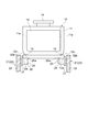
- FIG. 3 is a cross-sectional view of a conveyor section taken along line III-III in FIG. 2.
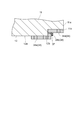
- FIG. 5 is a cross-sectional view of the cleaning unit along line VV in FIG. 4.
- FIG. 6 is a cross-sectional view of the cleaning unit along line VI-VI in FIG. 5.
- It is sectional drawing of the conveyor part of the conveyor apparatus of other embodiment of this invention. It is sectional drawing of the cleaning part of the conveyor apparatus of FIG. It is a perspective view of the cleaning part of another conveyor apparatus.
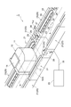
- the transport system 100 includes a conveyor device 1 that transports the transported object 10 along the transport path R, and a storage device (so-called stocker) 2 that stores the transported object 10. Yes.
- the conveyor apparatus 1 is installed in a clean room for manufacturing semiconductor devices.
- the transported object 10 is a cassette (so-called FOUP (Front Opening Unified Pod)) containing a plurality of semiconductor wafers.
- a direction changing device 3 that changes the transport direction of the object to be transported 10 is installed. Further, at a predetermined position on the transport path R, the unloading port 4 for unloading the transported object 10 from the transport path R into the storage apparatus 2 and the transported object from the storage apparatus 2 onto the transport path R. A carry-in port 5 for carrying 10 is installed. Further, at a predetermined position on the transport path R, an unloading port 6 for unloading the transport object 10 from the transport path R to the outside of the transport system 100, and a transport object on the transport path R from the outside of the transport system 100. A carry-in port 7 for carrying 10 is installed. In addition, when the to-be-conveyed object 10 is conveyed between the conveyance system 100 and another conveyance system via the ports 6 and 7, an overhead traveling type automatic guided vehicle, an automatic guided vehicle, a tracked automatic guided vehicle Etc. are used.
- the conveyor apparatus 1 includes a conveyor unit 20 that conveys the object to be conveyed 10 along the conveyance path R, and a cleaning unit 30 that cleans a predetermined portion of the object to be conveyed 10 on the conveyance path R.
- the object to be conveyed 10 includes an accommodating part 11 that accommodates a plurality of semiconductor wafers (articles), and a direction (here, substantially perpendicular to the conveying direction A from the bottom of the accommodating part 11. And a pair of supported portions (predetermined portions) 12 projecting in the left and right sides with respect to the transport direction A.
- the accommodating part 11 is formed in a substantially rectangular parallelepiped box shape.
- a lid 13 for taking in and out the semiconductor wafer is detachably provided on the front surface of the accommodating portion 11.
- the front end portion of the accommodating portion 11 provided with the lid 13 is widened in a direction substantially perpendicular to the transport direction A, and the bottom thereof is substantially the same width as the side surface 11a of the opposing accommodating portion 11 in the direction. It is narrowed down to.
- a flange portion 14 that is chucked by the overhead traveling automatic guided vehicle is provided on the upper surface of the housing portion 11.
- Each of the pair of supported portions 12 is formed in a substantially rectangular plate shape having the transport direction A as a longitudinal direction, and includes a lower surface (first surface) 12a, a side surface (second surface) 12b, and an upper surface (third). Surface) 12c.
- the conveyor unit 20 includes a pair of conveyor units 21 arranged on one side and the other side (here, left and right sides) in the transport direction A in the transport path R. It is comprised by connecting along.
- the pair of conveyor units 21 has a pair of support plates 22 erected substantially in parallel along the transport direction A. Inside each support plate 22, a drive pulley 23, a driven pulley 24 and a plurality of support rollers 25 are rotatably mounted.
- An endless annular belt (support portion) 26 is attached to the pulleys 23, 24 and the rollers 25. It is hung.
- a flange portion (regulating portion) 27 is integrally formed on the outer edge portion of the belt 26 so as to be erected with respect to the conveying surface 26 a of the belt 26.
- the driving pulley 23 is driven, so that the driven pulley 24 and the plurality of support rollers 25 are driven and the belt 26 circulates.
- the lower surface 12 a of one supported portion 12 of the object to be conveyed 10 is in contact with one belt 26, and the other supported of the object to be conveyed 10 is in contact with the other belt 26.
- the lower surface 12a of the part 12 contacts.
- the belt 26 contacts the lower surface 12a of the supported portion 12 and supports the conveyed object 10.
- the flange portion 27 of one belt 26 is in contact with the side surface 12b of one supported portion 12 of the object to be conveyed 10
- the flange portion 27 of the other belt 26 is in contact with the other object to be conveyed 10 of the other object.
- the side surface 12b of the support part 12 contacts.
- the flange portion 27 abuts on the side surface 12b of the supported portion 12 and restricts the movement of the conveyed object 10 in a direction substantially perpendicular to the conveying direction A.
- the cleaning unit 30 includes a pair of cleaning units 31 arranged on one side and the other side (here, both left and right sides) with respect to the transport direction A. It is configured by being installed at a position. As shown in FIG. 1, the position where the cleaning unit 30 is installed is a position immediately before the carry-out ports 4 and 6. More specifically, as shown in FIG. 2, the cleaning unit 30 is disposed between the free rollers 29 and 29 of the length adjustment unit 28 installed immediately before the conveyor unit 21 serving as the unloading port 4 (or unloading port 6). The cleaning unit 31 is installed.
- the length adjustment unit 28 is disposed between the pair of conveyor units 21 that serve as the carry-out ports 4 and the pair of conveyor units 21 that are adjacent to each other (that is, upstream in the transport direction A).
- each cleaning unit 31 includes a cover body 32 that is formed so as to cover a part of the supported portion 12 of the conveyed object 10 from above, below, and from the side.
- the cover body 32 is supported via an opening 33a formed so as to face the lower surface 12a of the supported portion 12 through a predetermined gap G1 (for example, 1 mm to 2 mm) and a predetermined gap G2 (for example, 4 mm to 8 mm).
- An opening 33b formed so as to face the side surface 12b of the portion 12, and an opening 33c formed so as to face the upper surface 12c of the supported portion 12 via a predetermined gap G3 (for example, 1 mm to 2 mm).
- the openings 33a, 33b, and 33c are formed continuously.
- a dust removing member (first dust removing portion) 34a is attached to the cover body 32 so as to contact the lower surface 12a of the supported portion 12 at the opening 33a. Further, a dust removing member (second dust removing portion) 34b is attached to the cover body 32 so as to contact the side surface 12b of the supported portion 12 at the opening 33b. Furthermore, a dust removing member (third dust removing portion) 34c is attached to the cover body 32 so as to contact the upper surface 12c of the supported portion 12 at the opening 33c.
- These dust removing members 34a, 34b, and 34c constitute a dust removing portion 34 that removes dust from the supported portion 12 of the conveyed object 10.
- a continuous space S is formed so as to surround the upstream and downstream sides of the dust removing unit 34 in the transport direction A and the outside of the dust removing unit 34.
- Each dust removing member 34a, 34b, 34c is made of a brush-like member (eg, pile, moquette, etc.) in which fine hairs are planted at a high density on a sheet so that fine dust can be swept away. Yes.
- the hair of each dust removing member 34a, 34b, 34c is made of nylon, polyethylene, PET (polyethylene terephthalate), or the like.
- the dust removing members 34a, 34b, 34c Nylon, polyethylene, PET, or the like, which is a hair material, may be subjected to conductive treatment, or carbon or stainless steel may be added.
- the dust removing member 34 a is fixed to the lower holding member 35 so that the hair contacts the lower surface 12 a of the supported portion 12. Further, the dust removing member 34 c is fixed to the upper holding member 36 so that the hair thereof contacts the upper surface 12 c of the supported portion 12.
- Each holding member 35, 36 is disposed in the cover body 32 and is fixed to the inner surface of the cover body 32. Further, the dust removing member 34 b is fixed to the elastic member 37 so that the hair contacts the side surface 12 b of the supported portion 12.
- the elastic member 37 is made of an elastic body such as sponge, and is held between the holding members 35 and 36 in a state of facing the side surface 12 b of the supported portion 12.
- the dust removing member 34 b is supported by the elastic member 37 disposed so as to face the side surface 12 b of the supported portion 12.
- at least an upstream end in the transport direction A (here, an upstream end and a downstream end in the transport direction A) has a convex curved shape when viewed from above. It is chamfered.
- the front end portion 38 a of the duct 38 is connected to the cover body 32, and the front end portion 38 a is open to the space S in the cover body 32.
- the base end portion of the duct 38 is connected to a dust suction portion 39 as shown in FIG. Thereby, the dust suction part 39 communicates with the inside of the cover body 32.
- the dust suction unit 39 sucks the dust removed by the dust removal unit 34 together with the surrounding atmosphere by forming a predetermined negative pressure, and collects the sucked dust by a filter provided in the dust suction unit 39.
- the auxiliary brush 40 is provided so as to sweep the area where the dust removing member 34c does not reach on the upper surface 12c.
- the dust on the upper surface 12 c swept by the auxiliary brush 40 is covered by the cover body 32 immediately after being swept and sucked by the dust suction portion 39.
- the dust removing member 34a comes into contact with the lower surface 12a of the supported portion 12 when the conveyed object 10 conveyed by the conveyor portion 20 passes through the cleaning portion 30.
- the dust removing member 34 b comes into contact with the side surface 12 b of the supported portion 12, and the dust removing member 34 c comes into contact with the upper surface 12 c of the supported portion 12. Thereby, dust is removed from the lower surface 12a, the side surface 12b, and the upper surface 12c of the supported portion 12.
- the dust removing members 34 a, 34 b and 34 c are attached to the cover body 32, and come into contact with the supported portion 12 of the conveyed object 10 at the openings 33 a, 33 b and 33 c of the cover body 32.
- the dust removed by the dust removing members 34 a, 34 b, 34 c is suppressed from diffusing outside the cover body 32, and is sucked into the dust suction part 39 through the space S in the cover body 32. Therefore, according to the conveyor apparatus 1, when removing dust from the to-be-conveyed object 10, the spreading
- the cleaning portion 30 having the dust removing member 34a indicates that the conveyed object 10 This is effective in accurately removing dust from the water.
- the cleaning portion 30 may include the dust removing member 34b. This is effective in accurately removing dust from the water.
- the components of the conveyor unit 20 are not in direct contact, dust adheres to the upper surface 12c of the supported portion 12 adjacent to the side surface 12b of the supported portion 12 due to an increase in the conveying speed of the object to be conveyed 10 or the like. Therefore, the cleaning unit 30 having the dust removing member 34c is also effective in accurately removing dust from the transported object 10.
- the dust removing members 34 a, 34 b, 34 c are attached to one cover body 32, so that dust adheres to the transported object 10 while reducing the size of the cleaning unit 30. Dust can be removed from the lower surface 12a, the side surface 12b, and the upper surface 12c of the supported portion 12 easily.
- the cleaning unit 30 is installed at a position immediately before the carry-out ports 4 and 6 in the transport system 100. Therefore, the object 10 to which the dust is attached is prevented from being carried out from the conveying path R into the storage device 2 and from the conveying path R to the outside of the conveying system 100. That is, it is possible to prevent dust adhering to the object to be transported 10 in the conveyor device 1 from being brought into the storage device 2 or another transport system.
- the dust removing member 34b is supported by an elastic member 37 disposed so as to face the side surface 12b of the supported portion 12. As a result, even if the transported object 10 shakes or shakes in a direction substantially perpendicular to the transport direction A, such movement of the transported object 10 is absorbed by the elastic member 37 and the supported portion 12 Dust is accurately removed from the side surface 12b. Further, in the dust removing member 34b, at least the upstream end in the transport direction A is chamfered into a convex curved surface. Thereby, even if the conveyed object 10 shakes or shakes in a direction substantially perpendicular to the conveying direction A, the conveyed object 10 is prevented from being caught by the dust removing member 34b.
- an auxiliary brush 40 is provided in front of the cover body 32.
- region which the dust removal member 34c does not reach on the upper surface 12c of the supported part 12 is swept away.
- the dust that has been swept by the auxiliary brush 40 is covered by the cover body 32 immediately after being swept away, and is prevented from diffusing into the surrounding atmosphere, and is transferred to the dust suction portion 39 via the space S in the cover body 32. Sucked.
- the side surface 11 a of the accommodating portion 11 is formed in a substantially flat shape, and the side surface 12 b of the supported portion 12 is positioned inside the side surface 11 a of the accommodating portion 11. You may do it.
- the cleaning unit 31 is configured as follows. That is, as shown in FIG. 8, the cleaning unit 31 is provided with a dust removing member (third dust removing portion) 34d instead of the dust removing member 34c.
- the dust removing unit 34 is configured by the dust removing members 34a, 34b, and 34d.
- the dust removing member 34d is attached to the cover body 32 such that the hair contacts the lower surface 11c of the accommodating portion 11 at the opening of the cover body 32.
- the structural member of the conveyor part 20 does not contact directly, it can remove dust from the lower surface 11c of the accommodating part 11 to which dust adheres easily due to adjoining with the side surface 12b of the supported part 12.
- the conveyor unit 20 is not limited to the belt type conveyor as described above, and may be a roller type conveyor. Further, a roller may be used in place of the flange portion 27 formed integrally with the belt 26 as a restricting portion that restricts the movement of the conveyed object 10 in a direction substantially perpendicular to the conveying direction A.
- the dust removing members 34a, 34b, 34c are brush-like members (for example, piles) in which thin hairs are planted at high density on the sheet. , Moquette, etc.) may be formed integrally.
- the length of the hair of the dust removing member 34b may be longer than the length of the hair of the dust removing members 34a and 34c.
- the conveyor device 1 is not limited to a device installed in a clean room for manufacturing semiconductor devices, and the object to be transferred 10 is not limited to a cassette containing a plurality of semiconductor wafers.
- the present invention can be applied to a cassette containing a photomask (reticle), a glass substrate, or the like. And not only the material and shape mentioned above but various materials and shapes can be applied to the material and shape of the component of the conveyor apparatus 1 and the to-be-conveyed object 10.
- a spray nozzle 41 and a suction nozzle 42 may be provided instead of the cleaning unit 31 or the auxiliary brush 40 described above or together with the cleaning unit 31.
- the spray nozzle 41 and the suction nozzle 42 are configured as follows. That is, the spray nozzle 41 is disposed obliquely so that the injection hole 41a faces the part of the supported portion 12 from the upstream side and the outside in the transport direction A.
- the suction nozzle 42 is disposed obliquely so that the suction port 42a faces the part of the supported portion 12 from the downstream side and the outside in the transport direction A.
- gas such as air injected from the injection hole 41a of the spray nozzle 41
- gas is sprayed on the supported part 12 in a state facing the transport direction A.
- the dust removed from the supported portion 12 is sucked into the suction port 42a of the suction nozzle 42 together with the gas while preventing diffusion to the surrounding atmosphere.
Landscapes
- Engineering & Computer Science (AREA)
- Mechanical Engineering (AREA)
- Container, Conveyance, Adherence, Positioning, Of Wafer (AREA)
- Cleaning In General (AREA)
Abstract
L'invention porte sur un dispositif de transporteur, qui comporte : une unité de transporteur qui transfère, le long d'une trajectoire de transfert, un sujet à transférer (10) ; et une unité de nettoyage (30) qui nettoie, sur la trajectoire de transfert, une partie à supporter (12), ladite partie étant une partie du sujet à transférer (10). L'unité de nettoyage (30) a un corps de revêtement (32), une unité de retrait de poussière (34) et une unité d'aspiration de poussière. Le corps de revêtement (32) comporte des ouvertures (33a, 33b, 33c) qui sont formées de façon à faire face à la partie à supporter (12) par le fait d'avoir des espaces prédéterminés (G1, G2, G3) entre celles-ci. L'unité de retrait de poussière (34) est attachée au corps de revêtement (32) de sorte que l'unité de retrait de poussière soit en contact, dans les ouvertures (33a, 33b, 33c), avec la partie à supporter (12), et l'unité de retrait de poussière retire de la poussière à partir de la partie à supporter (12). L'unité d'aspiration de poussière communique avec l'intérieur du corps de revêtement (32), et aspire la poussière qui a été retirée à l'aide de l'unité de retrait de poussière (34).
Applications Claiming Priority (2)
| Application Number | Priority Date | Filing Date | Title |
|---|---|---|---|
| JP2011-115748 | 2011-05-24 | ||
| JP2011115748A JP2014141311A (ja) | 2011-05-24 | 2011-05-24 | コンベア装置 |
Publications (1)
| Publication Number | Publication Date |
|---|---|
| WO2012160853A1 true WO2012160853A1 (fr) | 2012-11-29 |
Family
ID=47216942
Family Applications (1)
| Application Number | Title | Priority Date | Filing Date |
|---|---|---|---|
| PCT/JP2012/055467 Ceased WO2012160853A1 (fr) | 2011-05-24 | 2012-03-02 | Dispositif de transporteur |
Country Status (3)
| Country | Link |
|---|---|
| JP (1) | JP2014141311A (fr) |
| TW (1) | TW201302580A (fr) |
| WO (1) | WO2012160853A1 (fr) |
Cited By (10)
| Publication number | Priority date | Publication date | Assignee | Title |
|---|---|---|---|---|
| WO2015174981A1 (fr) * | 2014-05-15 | 2015-11-19 | Applied Materials, Inc. | Dispositif d'élimination de particules et son procédé de fonctionnement |
| CN106540892A (zh) * | 2015-09-17 | 2017-03-29 | 杨家军 | 电池极片分条机双毛刷辊除尘机构 |
| CN107170667A (zh) * | 2017-05-25 | 2017-09-15 | 昆山国显光电有限公司 | 基板湿制程工艺方法及基板湿制程工艺装置 |
| CN107640509A (zh) * | 2017-10-10 | 2018-01-30 | 徐美琴 | 一种自动传输物品的设备 |
| CN108480254A (zh) * | 2018-05-03 | 2018-09-04 | 安吉县大志家具制造有限公司 | 一种用于家具加工中的板材刷灰装置 |
| CN108672330A (zh) * | 2018-05-03 | 2018-10-19 | 安吉县大志家具制造有限公司 | 一种家具加工中的板材刷灰装置 |
| JP2019071447A (ja) * | 2018-12-19 | 2019-05-09 | アプライド マテリアルズ インコーポレイテッドApplied Materials,Incorporated | 粒子除去デバイス、及び粒子除去デバイスを操作する方法 |
| WO2019220636A1 (fr) * | 2018-05-18 | 2019-11-21 | ヤマハ発動機株式会社 | Dispositif de transport de substrat et dispositif de montage de composant |
| WO2022128113A1 (fr) * | 2020-12-17 | 2022-06-23 | Applied Materials, Inc. | Tête de nettoyage de support pour nettoyage de support se déplaçant le long d'une direction de transport, système de traitement de substrat, procédé de maintien de système de traitement de substrat et procédé de fabrication de dispositif |
| WO2022128112A1 (fr) * | 2020-12-17 | 2022-06-23 | Applied Materials, Inc. | Rouleau pour ensemble de transport de support, système de traitement de substrat, procédé de maintenance d'un système de traitement de substrat, et procédé de fabrication d'un dispositif |
Families Citing this family (1)
| Publication number | Priority date | Publication date | Assignee | Title |
|---|---|---|---|---|
| CN108435623A (zh) * | 2018-05-03 | 2018-08-24 | 安吉县大志家具制造有限公司 | 一种家具加工中板材的清灰装置 |
Citations (10)
| Publication number | Priority date | Publication date | Assignee | Title |
|---|---|---|---|---|
| JPS51125764U (fr) * | 1975-04-02 | 1976-10-12 | ||
| JPS55145582A (en) * | 1979-04-28 | 1980-11-13 | Keibunsha Seisakusho | Device for automatically washing seedling raising box |
| JPS56129879U (fr) * | 1980-03-03 | 1981-10-02 | ||
| JPS58224188A (ja) * | 1982-06-23 | 1983-12-26 | Yamamoto Kanematsu | 鋼矢板の連続泥、錆等除去装置 |
| JPH03127627U (fr) * | 1990-04-06 | 1991-12-24 | ||
| JPH078867A (ja) * | 1992-11-27 | 1995-01-13 | Satzinger Gmbh & Co | ことに鎖、軌条の塗布、浄化装置 |
| JP2006273442A (ja) * | 2005-03-28 | 2006-10-12 | Ishino Seisakusho Co Ltd | 循環型飲食容器搬送装置用清掃装置 |
| JP2006282285A (ja) * | 2005-03-31 | 2006-10-19 | Asyst Shinko Inc | ローラ式コンベアにおける塵埃処理装置 |
| US20090223781A1 (en) * | 2008-03-05 | 2009-09-10 | Basil Andrews | Drive chain or belt brush cleaner and method |
| JP2010013269A (ja) * | 2008-07-07 | 2010-01-21 | Nix Inc | コンベアクリーナ及びダスト除去装置 |
-
2011
- 2011-05-24 JP JP2011115748A patent/JP2014141311A/ja not_active Withdrawn
-
2012
- 2012-03-02 WO PCT/JP2012/055467 patent/WO2012160853A1/fr not_active Ceased
- 2012-05-21 TW TW101118010A patent/TW201302580A/zh unknown
Patent Citations (10)
| Publication number | Priority date | Publication date | Assignee | Title |
|---|---|---|---|---|
| JPS51125764U (fr) * | 1975-04-02 | 1976-10-12 | ||
| JPS55145582A (en) * | 1979-04-28 | 1980-11-13 | Keibunsha Seisakusho | Device for automatically washing seedling raising box |
| JPS56129879U (fr) * | 1980-03-03 | 1981-10-02 | ||
| JPS58224188A (ja) * | 1982-06-23 | 1983-12-26 | Yamamoto Kanematsu | 鋼矢板の連続泥、錆等除去装置 |
| JPH03127627U (fr) * | 1990-04-06 | 1991-12-24 | ||
| JPH078867A (ja) * | 1992-11-27 | 1995-01-13 | Satzinger Gmbh & Co | ことに鎖、軌条の塗布、浄化装置 |
| JP2006273442A (ja) * | 2005-03-28 | 2006-10-12 | Ishino Seisakusho Co Ltd | 循環型飲食容器搬送装置用清掃装置 |
| JP2006282285A (ja) * | 2005-03-31 | 2006-10-19 | Asyst Shinko Inc | ローラ式コンベアにおける塵埃処理装置 |
| US20090223781A1 (en) * | 2008-03-05 | 2009-09-10 | Basil Andrews | Drive chain or belt brush cleaner and method |
| JP2010013269A (ja) * | 2008-07-07 | 2010-01-21 | Nix Inc | コンベアクリーナ及びダスト除去装置 |
Cited By (16)
| Publication number | Priority date | Publication date | Assignee | Title |
|---|---|---|---|---|
| JP2017520112A (ja) * | 2014-05-15 | 2017-07-20 | アプライド マテリアルズ インコーポレイテッドApplied Materials,Incorporated | 粒子除去デバイス、及び粒子除去デバイスを操作する方法 |
| WO2015174981A1 (fr) * | 2014-05-15 | 2015-11-19 | Applied Materials, Inc. | Dispositif d'élimination de particules et son procédé de fonctionnement |
| CN106540892A (zh) * | 2015-09-17 | 2017-03-29 | 杨家军 | 电池极片分条机双毛刷辊除尘机构 |
| CN107170667A (zh) * | 2017-05-25 | 2017-09-15 | 昆山国显光电有限公司 | 基板湿制程工艺方法及基板湿制程工艺装置 |
| CN107170667B (zh) * | 2017-05-25 | 2020-07-28 | 昆山国显光电有限公司 | 基板湿制程工艺方法及基板湿制程工艺装置 |
| CN107640509B (zh) * | 2017-10-10 | 2020-06-19 | 徐美琴 | 一种自动传输物品的设备 |
| CN107640509A (zh) * | 2017-10-10 | 2018-01-30 | 徐美琴 | 一种自动传输物品的设备 |
| WO2019071936A1 (fr) * | 2017-10-10 | 2019-04-18 | 徐美琴 | Équipement pour la transmission automatique d'articles |
| CN108480254A (zh) * | 2018-05-03 | 2018-09-04 | 安吉县大志家具制造有限公司 | 一种用于家具加工中的板材刷灰装置 |
| CN108672330A (zh) * | 2018-05-03 | 2018-10-19 | 安吉县大志家具制造有限公司 | 一种家具加工中的板材刷灰装置 |
| JPWO2019220636A1 (ja) * | 2018-05-18 | 2021-02-12 | ヤマハ発動機株式会社 | 基板搬送装置及び部品実装装置 |
| WO2019220636A1 (fr) * | 2018-05-18 | 2019-11-21 | ヤマハ発動機株式会社 | Dispositif de transport de substrat et dispositif de montage de composant |
| JP2019071447A (ja) * | 2018-12-19 | 2019-05-09 | アプライド マテリアルズ インコーポレイテッドApplied Materials,Incorporated | 粒子除去デバイス、及び粒子除去デバイスを操作する方法 |
| WO2022128113A1 (fr) * | 2020-12-17 | 2022-06-23 | Applied Materials, Inc. | Tête de nettoyage de support pour nettoyage de support se déplaçant le long d'une direction de transport, système de traitement de substrat, procédé de maintien de système de traitement de substrat et procédé de fabrication de dispositif |
| WO2022128112A1 (fr) * | 2020-12-17 | 2022-06-23 | Applied Materials, Inc. | Rouleau pour ensemble de transport de support, système de traitement de substrat, procédé de maintenance d'un système de traitement de substrat, et procédé de fabrication d'un dispositif |
| CN116635994A (zh) * | 2020-12-17 | 2023-08-22 | 应用材料公司 | 用于载体运输组件的辊子、基板处理系统、维护基板处理系统的方法、以及制造装置的方法 |
Also Published As
| Publication number | Publication date |
|---|---|
| JP2014141311A (ja) | 2014-08-07 |
| TW201302580A (zh) | 2013-01-16 |
Similar Documents
| Publication | Publication Date | Title |
|---|---|---|
| WO2012160853A1 (fr) | Dispositif de transporteur | |
| JP3919464B2 (ja) | 搬送装置、洗浄装置及び現像装置 | |
| CN108878314A (zh) | 基板清洗装置、基板处理装置及基板清洗方法 | |
| JP5445762B2 (ja) | 画像形成装置 | |
| JP2013045877A (ja) | 基板処理装置 | |
| WO2011108215A1 (fr) | Dispositif de stockage de substrats | |
| TW201310568A (zh) | 基板處理裝置 | |
| JP2006294786A (ja) | 基板搬送システム | |
| TW201017804A (en) | Processing system | |
| CN118213309A (zh) | 基板处理装置 | |
| KR20040060713A (ko) | 판 형상체의 반송 장치 | |
| KR101568050B1 (ko) | 기판 처리 장치 | |
| KR101073546B1 (ko) | 스토커 | |
| JP3067752B2 (ja) | 板状部品塵埃除去装置 | |
| KR20110062531A (ko) | 기판 세정 유닛, 상기 유닛을 포함하는 기판 처리 장치 및 상기 장치를 이용한 기판 처리 방법 | |
| JP4062437B2 (ja) | 基板洗浄装置および基板処理施設 | |
| JP4280075B2 (ja) | 基板の処理装置 | |
| KR100741153B1 (ko) | 기판반송장치 | |
| JP2004273696A (ja) | 切断装置 | |
| JPS62128539A (ja) | ウエハの搬送装置 | |
| JP4663919B2 (ja) | 基板乾燥装置 | |
| JP4213805B2 (ja) | 乾燥処理装置 | |
| JP4509613B2 (ja) | 基板処理装置 | |
| KR101877428B1 (ko) | 기판 처리 장치 | |
| KR102936727B1 (ko) | 초박형 유리 기판의 기판 세정 장치 및 이에 사용되는 기판 캐리어 |
Legal Events
| Date | Code | Title | Description |
|---|---|---|---|
| 121 | Ep: the epo has been informed by wipo that ep was designated in this application |
Ref document number: 12789561 Country of ref document: EP Kind code of ref document: A1 |
|
| DPE1 | Request for preliminary examination filed after expiration of 19th month from priority date (pct application filed from 20040101) | ||
| NENP | Non-entry into the national phase |
Ref country code: DE |
|
| 122 | Ep: pct application non-entry in european phase |
Ref document number: 12789561 Country of ref document: EP Kind code of ref document: A1 |
|
| NENP | Non-entry into the national phase |
Ref country code: JP |