WO2012160948A1 - Système de notification et dispositif de notification - Google Patents
Système de notification et dispositif de notification Download PDFInfo
- Publication number
- WO2012160948A1 WO2012160948A1 PCT/JP2012/061361 JP2012061361W WO2012160948A1 WO 2012160948 A1 WO2012160948 A1 WO 2012160948A1 JP 2012061361 W JP2012061361 W JP 2012061361W WO 2012160948 A1 WO2012160948 A1 WO 2012160948A1
- Authority
- WO
- WIPO (PCT)
- Prior art keywords
- battery
- notification
- voltage
- equal
- unit
- Prior art date
- Legal status (The legal status is an assumption and is not a legal conclusion. Google has not performed a legal analysis and makes no representation as to the accuracy of the status listed.)
- Ceased
Links
Images


Classifications
-
- H—ELECTRICITY
- H04—ELECTRIC COMMUNICATION TECHNIQUE
- H04M—TELEPHONIC COMMUNICATION
- H04M1/00—Substation equipment, e.g. for use by subscribers
- H04M1/72—Mobile telephones; Cordless telephones, i.e. devices for establishing wireless links to base stations without route selection
- H04M1/724—User interfaces specially adapted for cordless or mobile telephones
- H04M1/72403—User interfaces specially adapted for cordless or mobile telephones with means for local support of applications that increase the functionality
- H04M1/72418—User interfaces specially adapted for cordless or mobile telephones with means for local support of applications that increase the functionality for supporting emergency services
Definitions
- the present invention relates to a notification system, and in particular, a notification system and a notification including a transmission terminal that transmits a notification command and a notification device that performs predetermined notification processing according to the notification command received from the transmission terminal It relates to the device.
- an emergency notification command is sent to a notification device that is wirelessly connected to the transmission terminal.
- An emergency notification system has been developed in which a notification device that transmits an emergency notification command and sends an emergency notification to an emergency notification reception center or the like via a telephone line or the like.
- an emergency notification command is sent to the notification device when the voltage of the battery falls below a predetermined threshold. It becomes impossible to send.
- the battery voltage is monitored, and when it is detected that the voltage has become equal to or lower than a predetermined threshold necessary for driving the transmission terminal, the notification device is informed that the battery has run out. There is something that has been.
- the internal impedance of the battery built in the transmitter terminal changes greatly depending on the environmental temperature used, and when the emergency notification command is transmitted to the reporting device, the voltage fluctuates greatly. It is difficult to detect in a stable state.
- Patent Document 1 Japanese Patent Laid-Open No. 2001-228221
- the charge of a lithium battery for driving a small wireless transmitter as a transmitting terminal is changed to a lithium battery. It is configured to detect the decrease in capacity of the lithium battery in a stable state with high accuracy by measuring the voltage of the lithium battery based on this electric charge.
- a battery capacity reduction detection circuit and a small wireless transmitter are disclosed.
- An object of the present invention is to eliminate the above-mentioned problems.
- the state is appropriately determined.
- the purpose is to provide a notification system and a notification device for reporting to the Internet.
- the first invention of the present application is a reporting system comprising: a transmitting terminal that transmits a notification command; and a reporting device that performs a reporting process according to the notification command received from the transmitting terminal.
- Voltage determination means for determining whether or not the voltage of the battery driving the transmitting terminal is equal to or lower than a predetermined threshold, and the number of times that the voltage is determined to be lower than or equal to the threshold in a predetermined time range
- a number-of-times determining means for determining whether or not the number of times is equal to or greater than a predetermined number of times, and a process of notifying that the battery is dead when the number of times that the voltage is equal to or less than the threshold is determined to be equal to or greater than the predetermined number of times
- a notification processing means for determining whether or not the voltage of the battery driving the transmitting terminal is equal to or lower than a predetermined threshold, and the number of times that the voltage is determined to be lower than or equal to the threshold in a predetermined time range
- the voltage determination means determines whether or not the voltage of the battery is equal to or lower than the threshold at a first time interval that is the time interval, When it is determined that the voltage is equal to or lower than the threshold value, it is determined whether the voltage of the battery is equal to or lower than the threshold value based on a second time interval that is the time interval shorter than the first time interval.
- the notification processing means performs a process of notifying that the battery is dead within a predetermined time zone. It is characterized by.
- the fourth invention of the present application is the notification system according to the third invention, wherein the time zone is a time zone excluding a specific time zone.
- the transmission terminal has a voltage of a battery that drives the transmission terminal equal to or lower than a predetermined threshold value.
- a transmission terminal comprising voltage determination means for determining whether or not there is a predetermined time interval, wherein the notification device has a predetermined number of times that the voltage is determined to be less than or equal to the threshold value within a predetermined time range.
- a number of times determination means for determining whether or not the number of times when the voltage is equal to or less than the threshold is determined to be greater than or equal to the predetermined number of times
- a notification processing means for performing a process of reporting that the battery is dead, It is characterized by providing.
- a sixth invention of the present application is a notification device that performs notification processing according to the notification command received from the transmission terminal that transmits the voltage of the battery that drives the transmission terminal and transmits the notification command
- the notification device includes the transmission Voltage determination means for determining whether or not the battery voltage received from the terminal is equal to or less than a predetermined threshold, and a predetermined number of times that the voltage is determined to be equal to or less than the threshold in a predetermined time range Number of times determination means for determining whether or not the number of times is not less than, and a notification process for performing a process of notifying that the battery is out of battery when the number of times that the voltage is equal to or less than the threshold is determined to be equal to or more than the predetermined number And means.
- the voltage determining means determines whether or not the voltage of the battery driving the transmitting terminal is equal to or lower than a predetermined threshold at a predetermined time interval, and the frequency determining means determines the voltage within a predetermined time range. Determining whether or not the number of times that the voltage is determined to be equal to or less than the threshold is greater than or equal to a predetermined number of times, and when the notification processing means determines that the number of times that the voltage is equal to or less than the threshold is equal to or greater than the predetermined number of times, A process for reporting that the battery is dead is performed.
- the voltage of the battery driving the transmitting terminal can be accurately determined in a stable state based on the averaged voltage. Can do. And when it determines with a voltage being below a predetermined threshold value, it can report appropriately that it is out of a battery.
- the battery voltage is determined at the first time interval, and when it is determined that the battery is dead, the battery is charged at a second time interval shorter than the first time interval.
- the reporting system when it is determined that the battery has run out, an inappropriate time is obtained by performing a process of reporting the battery running out within a predetermined time zone. It is possible to avoid the situation where the notification process is performed in the belt.
- the reporting time zone in the reporting system according to the third invention, by setting the reporting time zone to a specific time zone other than the time zone such as nighttime, for example, the notification is performed at night, so that it is sleeping The situation where the user's sleep is disturbed can be avoided.
- reporting apparatus which comprises the alerting
- FIG. 2 is a configuration block diagram of a receiving adapter constituting the notification system shown in FIG. 1.
- FIG. 2 is a configuration block diagram of a telephone unit constituting the notification system shown in FIG. 1.
- It is a process flowchart of the pendant part which comprises the notification system shown in FIG.
- It is a process flowchart of the telephone part which comprises the notification system shown in FIG.
- It is a timing chart of a battery exhaustion notification process in the telephone part which comprises the notification system shown in FIG.
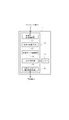
- FIG. 1 is a block diagram showing the configuration of a notification system 10 according to an embodiment of the present invention.
- the notification system 10 includes a pendant unit 11 that is a transmission terminal carried by a user, a reception adapter 12 that receives a command transmitted from the pendant unit 11 by wireless communication, and a USB connection to the reception adapter 12. Based on a command transmitted via the receiving adapter 12, a predetermined notification process is performed, and a telephone unit 13 which is a notification device having a function as an IP-TV telephone is provided.
- the telephone unit 13 is configured to be connectable to a transmission destination 15 set corresponding to the pendant unit 11 via a network 14 such as an optical communication network. Note that a plurality of pendant units 11 that can be individually identified by the ID information can be connected to the receiving adapter 12.
- FIG. 2 is a configuration block diagram of the pendant unit 11 constituting the notification system 10.
- the pendant unit 11 includes a control unit 17 that controls the operation of the pendant unit 11 with electric power supplied from a battery 16 such as a built-in lithium battery.
- the control unit 17 includes a button press monitoring unit 18, a timer monitoring unit 19, a voltage monitoring unit 20, and a data transmission control unit 21.
- the button press monitoring unit 18 monitors, for example, whether or not the button 22 is pressed by the user in an emergency.
- the timer monitoring unit 19 controls the start (time measurement start), reset, and switching of the first timer 23 and the second timer 24 having different set time over times T1 and T2, and monitors the time measurement.
- the voltage monitoring unit 20 is connected to the battery 16 when the battery 16 is inserted into the pendant unit 11, when the user presses the button 22, or when the time measured by the first timer 23 or the second timer 24 has expired. Monitor the voltage.
- the data transmission control unit 21 performs control to generate an emergency notification command together with ID information for specifying the pendant unit 11 and wirelessly transmit it to the reception adapter 12.
- the data transmission control unit 21 functions as a voltage determination unit that determines whether or not the voltage of the battery 16 monitored by the voltage monitoring unit 20 is equal to or lower than a predetermined threshold, and the voltage of the battery 16 is equal to or lower than the predetermined threshold. When it is determined, the battery control unit generates a battery deadline notification command together with the ID information and performs wireless transmission to the receiving adapter 12.
- FIG. 3 is a block diagram showing the configuration of the receiving adapter 12 constituting the notification system 10.
- the reception adapter 12 includes a control unit 25.
- the control unit 25 includes a wireless data reception control unit 26, an operation state monitoring unit 27, a setting data storage unit 28, an LED control unit 29, and a USB message transmission / reception control unit 30.
- the wireless data reception control unit 26 performs control to receive ID information, an emergency notification command, and a battery exhaustion notification command that are wirelessly transmitted from the pendant unit 11.
- the operation state monitoring unit 27 monitors the registration state of the reception adapter 12 with respect to the telephone unit 13, the registration state of the pendant unit 11 with respect to the reception adapter 12, and the transmission state of data from the pendant unit 11.
- the setting data storage unit 28 stores the ID information of the receiving adapter 12, the ID information of the pendant unit 11 connected to the receiving adapter 12, and the number of registered units.
- the LED control unit 29 performs control to display each state monitored by the operation state monitoring unit 27 according to lighting, blinking, lighting, and blinking time intervals of the LED 31.
- the USB message transmission / reception control unit 30 performs control to transmit the ID information, the emergency notification command, and the battery exhaustion notification command of the pendant unit 11 wirelessly transmitted from the pendant unit 11 to the telephone unit 13 via the USB cable.
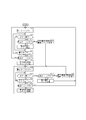
- FIG. 4 is a configuration block diagram of the telephone unit 13 constituting the notification system 10.
- the telephone unit 13 includes a control unit 32.
- the control unit 32 includes a USB message transmission / reception control unit 33, a display / key control unit 34, a setting data storage unit 35, a log storage unit 36, a notification operation determination unit 37, a notification operation control unit 38 and a telephone control unit 39.
- the USB message transmission / reception control unit 33 transmits / receives a signal to / from the reception adapter 12, and transmits the ID information of the pendant unit 11, an emergency notification command, and a battery exhaustion notification command transmitted from the pendant unit 11 through the reception adapter 12. Control to receive.
- the display / key control unit 34 controls the display unit 40 and the key 41 to display various functions as an IP-TV telephone and to control key input, and also to an emergency call start command and / or a battery deadline report start command. Based on the notification image display control.
- the setting data storage unit 35 stores the ID information of the receiving adapter 12, the ID information of the pendant unit 11 connected to the receiving adapter 12, and the registered number of the same as the setting data storage unit 28 of the receiving adapter 12. In addition, the setting data storage unit 35 stores the telephone number of the transmission destination 15 that transmits an emergency call from the user carrying the pendant unit 11 in association with the ID information of the pendant unit 11.
- the log storage unit 36 includes an emergency notification command that is an operation request command transmitted from the pendant unit 11 via the reception adapter 12, a battery exhaustion notification command, and a log for the year, month, and date when the command is received. 11 together with ID information.
- the notification operation determination unit 37 and the notification operation control unit 38 operate as follows and function as notification processing means.
- the notification operation determination unit 37 analyzes the operation request command and determines whether the notification operation can be executed. For example, when an emergency notification command is transmitted from the pendant unit 11, the notification operation determination unit 37 issues an emergency notification start command to make an emergency notification. Further, the notification operation determination unit 37 checks the log of the battery exhaustion notification command transmitted from the pendant unit 11 and stored in the log storage unit 36, and the number (number of times) of battery exhaustion commands in a predetermined time range is predetermined.
- predetermined number it is determined whether or not the number (predetermined number) or more, and when it is equal to or greater than the predetermined number (predetermined number), it functions as a number-of-times determination unit that issues a battery deadline notification start command in order to report the battery dead.
- the notification operation control unit 38 controls the display / key control unit 34 according to the notification start command issued by the notification operation determination unit 37, and executes an emergency notification and / or a battery exhaustion notification control operation. Furthermore, the notification operation control unit 38 can perform notification according to the emergency notification and / or the battery exhaustion notification via the speaker 42.
- the telephone control unit 39 selects the destination 15 set corresponding to the ID information of the pendant unit 11 that has transmitted the emergency notification command from the setting data storage unit 35 in accordance with the emergency notification control operation by the notification operation control unit 38. Then, emergency information is sent to the destination 15 by telephone.
- FIG. 5 is a process flowchart in the pendant unit 11
- FIG. 6 is a process flowchart in the telephone unit 13.
- the timer monitoring unit 19 of the pendant unit 11 starts the first timer 23 and starts measuring time (step S101).
- step S102 the button pressing monitoring unit 18 detects that the emergency notification button 22 has been pressed by the user carrying the pendant unit 11 (step S102: YES)
- step S102 the button pressing monitoring unit 18 notifies the voltage monitoring unit 20 that the button 22 has been pressed.
- the voltage monitoring unit 20 supplies voltage data of the battery 16 at that time to the data transmission control unit 21.
- the data transmission control unit 21 determines whether or not the voltage of the battery 16 that is the data supplied from the voltage monitoring unit 20 is equal to or lower than a predetermined threshold that prevents the pendant unit 11 from operating normally. If it is determined that the value is higher than the threshold (step S103: YES), an emergency notification command based on pressing of the button 22 is generated and transmitted to the receiving adapter 12 together with the ID information of the pendant unit 11 (step S104).
- step S103 NO
- step S103 the data transmission control unit 21 determines that the voltage of the battery 16 is equal to or lower than the threshold
- step S105 the data transmission control unit 21 generates an emergency notification command and a battery exhaustion notification command, and displays these notification commands as a pendant.
- step S105 After being transmitted to the receiving adapter 12 together with the ID information of the unit 11 (step S105), the process proceeds to the process of step S109 described later (starting time measurement by the second timer 24).
- step S103 when the voltage of the battery 16 is higher than the predetermined threshold (step S103: YES), or when the button 22 is not pressed (step S102: NO), the processing from step S102 is repeated (step S106: NO). ).
- step S106 When the button 22 is not pressed and the time measured by the first timer 23 reaches the time over time T1 (for example, 168 hours) (step S106: YES), the data transmission control unit 21 monitors the voltage monitoring unit 20. The voltage of the battery 16 is compared with a predetermined threshold value. When it is determined that the voltage of the battery 16 is higher than the threshold (step S107: YES), the timer monitoring unit 19 resets the first timer 23 and then restarts the time measurement by the first timer 23 (step S101). ), The process from step S102 is repeated.
- step S106 When the time-over time T1 of the first timer 23 has elapsed (step S106: YES), the data transmission control unit 21 determines whether or not the voltage of the battery 16 is equal to or lower than a predetermined threshold, and is determined to be equal to or lower than the threshold. In such a case (step S107: NO), the data transmission control unit 21 generates a battery exhaustion notification command and transmits it to the reception adapter 12 together with the ID information of the pendant unit 11 (step S108).
- step S108 or S105 when the battery deadline notification command is transmitted to the receiving adapter 12, the timer monitoring unit 19 starts the second timer 24 and starts measuring time (step S109).
- the time over time T2 of the second timer 24 is set to a time shorter than the time over time T1 of the first timer 23 (for example, 12 hours).
- step S110: YES the voltage is monitored.
- the monitoring unit 20 is notified that the button 22 has been pressed, and the voltage monitoring unit 20 supplies the data of the voltage of the battery 16 at that time to the data transmission control unit 21.
- the data transmission control unit 21 determines whether or not the voltage of the battery 16 that is the data supplied from the voltage monitoring unit 20 is equal to or lower than a predetermined threshold that prevents the pendant unit 11 from operating normally. If it is determined that the value is higher than the threshold (step S111: YES), an emergency notification command based on pressing of the button 22 is generated and transmitted to the reception adapter 12 together with the ID information of the pendant unit 11 (step S112). Next, the timer monitoring unit 19 starts the first timer 23 again (step S101), and repeats the processing from step S102.
- step S111: NO when the data transmission control unit 21 determines that the voltage of the battery 16 is equal to or lower than the threshold (step S111: NO), the data transmission control unit 21 generates an emergency notification command and a battery exhaustion notification command, and sends these notification commands to the pendant unit 11.
- the ID information is transmitted to the receiving adapter 12 (step S113).
- step S109 the timer monitoring unit 19 restarts the time measurement by the second timer 24 (step S109), and repeats the processing from step S110. If the button 22 is not pressed after the second timer 24 is started (step S110: NO), the processing from step S110 is repeated (step S114: NO).
- step S114 When the button 22 is not pressed and the time measured by the second timer 24 reaches the time over time T2 (for example, 12 hours) (step S114: YES), the data transmission control unit 21 monitors the voltage monitoring unit 20. The voltage of the battery 16 is compared with a predetermined threshold value. When it is determined that the voltage of the battery 16 is higher than the threshold (step S115: YES), the timer monitoring unit 19 switches from the second timer 24 to the first timer 23, and starts the time measurement by the first timer 23 again. (Step S101), the processing from Step S102 is repeated.
- step S115 the case where it is determined in step S115 that the voltage of the battery 16 is higher than the threshold is, for example, the voltage of the battery 16 temporarily in a low-temperature environment or other fluctuation factors during the previous voltage check. Is lowered, and then the voltage returns to a normal value due to an increase in environmental temperature or the like.
- step S115 when it is determined that the voltage of the battery 16 is equal to or lower than the predetermined threshold (step S115: NO), the data transmission control unit 21 generates a battery deadline notification command and receives it together with the ID information of the pendant unit 11. It transmits to the adapter 12 (step S116). Next, the timer monitoring unit 19 restarts the second timer 24 (step S109) and repeats the processing from step S110.
- the notification operation determination unit 37 of the telephone unit 13 analyzes the operation request command transmitted from the reception adapter 12 and, based on pressing of the button 22 by the user carrying the pendant unit 11, the pendant unit via the reception adapter 12. If it is determined that an emergency notification command has been received from 11 (step S201: YES), the emergency notification command and the logs for the year, month, and date that received the emergency notification command are stored in the log storage unit 36 together with the ID information of the pendant unit 11 (step S201). S202). Next, the notification operation determination unit 37 issues an emergency notification start command according to the received emergency notification command (step S203), and supplies it to the notification operation control unit 38.
- the notification operation control unit 38 Upon receiving the emergency call start command, the notification operation control unit 38 executes an emergency call control operation. For example, the notification operation control unit 38 controls the display / key control unit 34 to notify that an emergency notification is transmitted from the user of the pendant unit 11 using the display unit 40 and drives the speaker 42. Then, an alarm for an emergency notification is notified. Furthermore, the notification operation control unit 38 selects the telephone number of the destination 15 stored in the setting data storage unit 35 according to the ID information of the pendant unit 11 that has transmitted the emergency notification command, and via the network 14, An emergency call is transmitted to the selected destination 15. The emergency notification may be sent to the family of the user who owns the pendant unit 11, or may be an emergency call reception server of a medical center provided in the area if the environment is in place.
- the notification operation determination unit 37 of the telephone unit 13 analyzes the operation request command transmitted from the reception adapter 12 and outputs a battery exhaustion notification command indicating that the voltage of the battery 16 of the pendant unit 11 is equal to or lower than the threshold value. If it is determined that it has been received (step S204: YES), the battery storage notification command and the logs for the year, month, and date that received it are stored in the log storage unit 36 together with the ID information of the pendant unit 11 (step S205). When the battery exhaustion notification command has not been received (step S204: NO), the processing from step S201 is repeated.
- the notification operation determination unit 37 determines whether or not the emergency notification command is received together with the battery running notification command. That is, the pendant unit 11 checks the voltage of the battery 16 when the user presses the button 22 (steps S103 and S111). Therefore, when both the emergency notification command and the battery exhaustion notification command are received (step S206: YES), the notification operation determination unit 37 issues a battery exhaustion notification start command according to the received battery exhaustion notification command (step S209). The notification operation control unit 38 is supplied.
- the notification operation control unit 38 that has received the battery low notification start command together with the emergency notification command executes a battery low notification control operation.
- the notification operation control unit 38 controls the display / key control unit 34 and uses the display unit 40 to notify that the battery 16 of the pendant unit 11 may run out of battery, and also drives the speaker 42. Then, the alarm of battery exhaustion is notified.
- the notification operation control unit 38 selects the telephone number of the call destination 15 stored in the setting data storage unit 35 according to the ID information of the pendant unit 11 that has transmitted the battery deadline notification command, and via the network 14. Then, a battery exhaustion notice is transmitted to the selected destination 15.
- step S201 when only the battery exhaustion notification command is received from the pendant unit 11 via the reception adapter 12 (step S201: NO, S206: NO), the notification operation determination unit 37 is a time zone in which the current time is a night time (for example, , 22:00 to 7:00).
- step S207 When it is determined that it is a night time zone (step S207: YES), the process from step S201 is repeated without performing the battery exhaustion notification process.
- step S207: NO the notification operation determination unit 37 logs the year, month, day, and time when the battery deadline notification command stored in the log storage unit 36 is received. Based on the above, it is determined whether or not the telephone unit 13 has received a battery exhaustion notification command N times or more (for example, four times or more) from the same pendant unit 11 within a predetermined time (for example, within 49 hours). If it is determined that the number of battery-out notification commands within the predetermined time is less than N (step S208: NO), the process from step S201 is repeated without performing the battery-out notification process.
- N for example, four times or more
- the notification operation determination unit 37 issues a battery deadline notification start command according to the received battery deadline notification command.
- the notification operation control unit 38 is supplied.
- the notification operation control unit 38 which has received the battery start notification start command controls the display / key control unit 34 and uses the display unit 40 to notify that the battery 16 of the pendant unit 11 may run out of battery,
- the speaker 42 is driven to notify a battery exhaustion alarm.
- the notification operation control unit 38 selects the telephone number of the call destination 15 stored in the setting data storage unit 35 according to the ID information of the pendant unit 11 that has transmitted the battery deadline notification command, and via the network 14. Then, a battery exhaustion notice is transmitted to the selected destination 15.
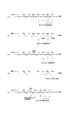
- FIG. 7 is a timing chart in the case where it is determined that the battery 16 has naturally deteriorated and the battery has run out, and a battery running notification is started.
- the pendant unit 11 checks the voltage of the battery 16 when the time measured by the first timer 23 has exceeded the time over time T1 (for example, 168 hours), and determines that the voltage is equal to or lower than a predetermined threshold value. Is sent to the telephone unit 13.
- This battery exhaustion notification command NG1 is stored in the log storage unit 36 of the telephone unit 13 together with the logs for the year, month, and date when the command is received.
- the pendant unit 11 checks the voltage of the battery 16 when a time-over time T2 (for example, 12 hours) shorter than the time-over time T1 elapses by the time measured by the second timer 24.
- a time-over time T2 for example, 12 hours
- T1 time-over time
- the voltage continues to be equal to or lower than the predetermined threshold value, and therefore the pendant unit 11 transmits a second battery exhaustion notification command NG2 to the telephone unit 13.
- This battery exhaustion notification command NG2 is stored in the log storage unit 36 together with a log for the year, month, and date when the command is received.
- the pendant unit 11 checks the voltage of the battery 16 every time the time-over time T2 elapses, determines that the voltage is not more than a predetermined threshold value, and notifies the third time, the fourth time,.
- Commands NG3, NG4,... Are transmitted to the telephone unit 13.
- These battery exhaustion notification commands NG3, NG4,... are sequentially stored in the log storage unit 36 together with the logs for the year, month, and date when the command is received.
- the telephone unit 13 determines whether or not the battery exhaustion notification commands NG1, NG2,... Received within a predetermined time are N times or more based on the logs for the year, month, day and time when the command is received, and N times When the above is reached (for example, four times or more), a battery exhaustion notification start command is issued, and then a battery exhaustion notification is made every time the battery exhaustion notification commands NG5, NG6,.
- (B) of FIG. 7 is a timing chart in the case of avoiding the time zone of the battery exhaustion notification at night, for example, 22:00 to 7:00.
- the telephone unit 13 receives the Nth battery exhaustion notification command within a predetermined time and reports the battery exhaustion, for example, the time when the fifth battery exhaustion notification command NG5 is received is 22:00 to When it is a night time zone in the range of 7:00, the battery exhaustion notification command NG5 is stored in the log storage unit 36, but the battery exhaustion notification based on the battery exhaustion notification command NG5 is not performed. Thereby, it is possible to avoid a situation in which a sleeping user or the like is bothered by reporting that the battery has run out at night. Note that the telephone unit 13 notifies the battery exhaustion when the sixth battery exhaustion notification command NG6 is received after the night time period has elapsed.
- (C) of FIG. 7 is a timing chart when reception of the battery exhaustion notification command from the pendant unit 11 fails.
- the telephone unit 13 allows a predetermined time for receiving the battery deadline notification command to be allowed to fail to receive one battery deadline notification command, and considers an error in signal transmission timing from the pendant unit 11,
- the battery exhaustion can be reported based on the received battery exhaustion notification commands NG4, NG5,... After the Nth (for example, the fourth) reception.
- (D) of FIG. 7 is a timing chart when the voltage of the battery 16 of the pendant unit 11 is restored in a low temperature environment and then recovered due to a temperature rise.
- the voltage of the battery 16 may temporarily decrease, and the pendant unit 11 may transmit a battery deadline notification command to the telephone unit 13.
- the pendant unit 11 determines that the battery has run out due to a voltage drop due to low temperature at the time when the time-over time T1 (for example, 168 hours) of the first timer 23 has elapsed, the pendant unit 11 transmits the battery running notification command NG1 to the telephone unit 13. .
- the pendant unit 11 switches the first timer 23 to the second timer 24 and checks the voltage of the battery 16 again after a time over time T2 (for example, 12 hours) by the second timer 24 has elapsed.
- the pendant unit 11 does not transmit a battery exhaustion notification command (OK).
- the voltage of the battery 16 is checked again. If it is determined that the battery has run out at this time, the pendant unit 11 transmits the battery running notification command NG1 to the telephone unit 13 and then switches to the second timer 24 to check the voltage in the same manner as described above.
- battery deadline notification commands NG2, NG3,... are sequentially transmitted to the telephone unit 13.
- the telephone unit 13 determines whether or not the battery exhaustion notification command NG1 (second battery exhaustion notification command NG1), NG2,. When it becomes N times or more (for example, 4 times or more), a battery low notification start command is issued, and then a battery low notification is received every time the battery low notification commands NG5, NG6,. I do.
- the telephone unit 13 subsequently increases the environmental temperature of the pendant unit 11 in the daytime and the voltage is increased.
- the first battery exhaustion notification command NG1 is excluded from the number of battery exhaustion notification commands received within (T2 ⁇ N + 1) hours. It is possible to avoid a situation where the battery is detected and an inappropriate battery exhaustion notification is made.
- (E) of FIG. 7 is a timing chart including the case where the button 22 of the pendant part 11 is pressed by the user.
- the pendant unit 11 checks the voltage of the battery 16, and when it is determined that the battery is exhausted, the pendant unit 11 transmits the battery exhaustion notification command to the telephone unit 13 together with the emergency notification command.
- the telephone unit 13 makes an emergency call and a battery deadline notification based on the battery deadline notification command transmitted together with the emergency notification command.
- the battery exhaustion notification since it is necessary to notify the emergency call even if the current time is midnight, it is not inconvenient to report the battery exhaustion at the same time.
- the number of times of the battery exhaustion notification command from the time when the time over time T1 switches to T2 is counted, and the battery exhaustion notification is notified when the number of times reaches N or more. The user can be notified without delay that the battery 16 of the pendant unit 11 is out of battery.
- this invention is not limited to the Example mentioned above, It can change in the range which does not deviate from the summary of this invention.
- the voltage check of the battery 16 in the pendant unit 11 is not performed when the user presses the button 22 or the first timer 23 and the second timer 24 are over, but the battery 16 is inserted into the pendant unit 11. It is preferable to do it on occasion.
- the voltage check of the battery 16 has been described as being performed by the pendant unit 11, but the voltage data monitored by the voltage monitoring unit 20 of the pendant unit 11 is transmitted to the telephone unit 13, and the voltage is checked by the telephone unit 13. You may make it check by comparing with a predetermined threshold value.
- the number N of battery-notification notification commands for reporting a battery exhaustion is as follows. May be set arbitrarily.
Landscapes
- Engineering & Computer Science (AREA)
- Business, Economics & Management (AREA)
- Emergency Management (AREA)
- Human Computer Interaction (AREA)
- Computer Networks & Wireless Communication (AREA)
- Signal Processing (AREA)
- Telephonic Communication Services (AREA)
- Alarm Systems (AREA)
- Telephone Function (AREA)
Abstract
L'invention concerne un système de notification qui détermine de manière stable et précise la tension d'un accumulateur qui alimente un terminal d'émission et qui, s'il est déterminé que l'accumulateur est épuisé, notifie cette situation de manière adéquate. Un système de notification (10) comprend : un terminal d'émission (11) destiné à émettre une instruction de notification; et un dispositif de notification (13) destiné à exécuter le traitement de notification en fonction de l'instruction de notification reçue du terminal d'émission (11). Le système de notification comprend en outre : un moyen de détermination de tension destiné à déterminer, sur une période de temps prédéterminée, si la tension d'un accumulateur qui alimente le terminal d'émission (11) est inférieure ou égale à un seuil prédéterminé; un moyen de détermination de fréquence destiné à déterminer si la fréquence à laquelle la tension est déterminée comme inférieure ou égale au seuil prédéterminé est égale ou supérieure à une fréquence prédéterminée, au cours d'une période de temps prédéterminée; et un moyen de traitement de notification destiné à exécuter le traitement afin de fournir une notification de l'épuisement de l'accumulateur, si la fréquence à laquelle la tension est inférieure ou égale au seuil est déterminée comme étant égale ou supérieure à la fréquence prédéterminée.
Applications Claiming Priority (2)
| Application Number | Priority Date | Filing Date | Title |
|---|---|---|---|
| JP2011-117978 | 2011-05-26 | ||
| JP2011117978A JP2012247909A (ja) | 2011-05-26 | 2011-05-26 | 通報システム |
Publications (1)
| Publication Number | Publication Date |
|---|---|
| WO2012160948A1 true WO2012160948A1 (fr) | 2012-11-29 |
Family
ID=47217031
Family Applications (1)
| Application Number | Title | Priority Date | Filing Date |
|---|---|---|---|
| PCT/JP2012/061361 Ceased WO2012160948A1 (fr) | 2011-05-26 | 2012-04-27 | Système de notification et dispositif de notification |
Country Status (2)
| Country | Link |
|---|---|
| JP (1) | JP2012247909A (fr) |
| WO (1) | WO2012160948A1 (fr) |
Cited By (2)
| Publication number | Priority date | Publication date | Assignee | Title |
|---|---|---|---|---|
| US9616835B2 (en) | 2013-03-21 | 2017-04-11 | Denso Corporation | Vehicle-mounted emergency report device |
| US11374412B2 (en) * | 2017-04-14 | 2022-06-28 | Parker House Mfg. Co., Inc. | Furniture power management system |
Families Citing this family (2)
| Publication number | Priority date | Publication date | Assignee | Title |
|---|---|---|---|---|
| JP6825259B2 (ja) * | 2016-08-04 | 2021-02-03 | いすゞ自動車株式会社 | 異常通知装置及び異常通知方法 |
| JP6841353B2 (ja) * | 2020-02-05 | 2021-03-10 | カシオ計算機株式会社 | 情報通知方法、情報通知装置、及びプログラム |
Citations (2)
| Publication number | Priority date | Publication date | Assignee | Title |
|---|---|---|---|---|
| JPH0954885A (ja) * | 1995-08-16 | 1997-02-25 | Nohmi Bosai Ltd | 火災警報器 |
| JP2010121361A (ja) * | 2008-11-19 | 2010-06-03 | Denso Corp | 電子キーシステム及び携帯機 |
Family Cites Families (1)
| Publication number | Priority date | Publication date | Assignee | Title |
|---|---|---|---|---|
| JP5156563B2 (ja) * | 2008-09-25 | 2013-03-06 | パナソニック株式会社 | 警報器 |
-
2011
- 2011-05-26 JP JP2011117978A patent/JP2012247909A/ja active Pending
-
2012
- 2012-04-27 WO PCT/JP2012/061361 patent/WO2012160948A1/fr not_active Ceased
Patent Citations (2)
| Publication number | Priority date | Publication date | Assignee | Title |
|---|---|---|---|---|
| JPH0954885A (ja) * | 1995-08-16 | 1997-02-25 | Nohmi Bosai Ltd | 火災警報器 |
| JP2010121361A (ja) * | 2008-11-19 | 2010-06-03 | Denso Corp | 電子キーシステム及び携帯機 |
Cited By (2)
| Publication number | Priority date | Publication date | Assignee | Title |
|---|---|---|---|---|
| US9616835B2 (en) | 2013-03-21 | 2017-04-11 | Denso Corporation | Vehicle-mounted emergency report device |
| US11374412B2 (en) * | 2017-04-14 | 2022-06-28 | Parker House Mfg. Co., Inc. | Furniture power management system |
Also Published As
| Publication number | Publication date |
|---|---|
| JP2012247909A (ja) | 2012-12-13 |
Similar Documents
| Publication | Publication Date | Title |
|---|---|---|
| CN101413992B (zh) | 降低夜间安保服务的低电量电池报告的特征 | |
| WO2003032271A1 (fr) | Procede de gestion d'un systeme de reseau a capteurs, programme de gestion dudit systeme, support d'enregistrement ayant un programme enregistre servant a gerer le systeme de reseau a capteurs, appareil de gestion du systeme de reseau a capteurs, procede de gestion du reseau de relais, programme destine a la gestion du rese | |
| JP2013009531A (ja) | 蓄電池監視システム及び蓄電池監視方法、サーバ装置及び蓄電池制御装置並びにサーバ装置用プログラム及び蓄電池制御装置用プログラム | |
| US20130343202A1 (en) | Access point synchronization in wi-fi fire detection systems | |
| WO2006070895A1 (fr) | Systeme de detection a distance et unite de capteur | |
| WO2012160948A1 (fr) | Système de notification et dispositif de notification | |
| JP4372800B2 (ja) | 電池切れ検出システム | |
| JP2015162967A (ja) | エネルギー管理システム、及びプログラム | |
| CN111293742B (zh) | 带有充电提醒的通信设备及方法 | |
| JP6641176B2 (ja) | 警備業務支援システムおよび警備装置 | |
| JP2009159679A (ja) | 管理システム及びそれに用いられるコンセント部 | |
| WO2013067794A1 (fr) | Procédé, dispositif, terminal et système d'avertissement avant la perte d'une communication en champ proche | |
| JP2004275272A (ja) | 生体情報端末、情報管理装置、生体情報収集システム、及び生体情報異常評価方法 | |
| JP2010029006A (ja) | アンテナ整流装置対応充電器 | |
| JP2009156639A (ja) | 管理システム | |
| JP2009159102A (ja) | 管理システム | |
| JP2005258600A (ja) | 火災報知設備のリモート監視用インタフェース装置および顧客サービスセンタ | |
| JP2021089500A (ja) | サーバ装置及びプログラム | |
| JP2007108884A (ja) | ワイヤレスセンサ及びこれを用いたワイヤレス監視システム | |
| CN113064088A (zh) | 物联网装置及电池电量检测方法 | |
| JP2014157440A (ja) | 火災報知設備 | |
| JP5251665B2 (ja) | 生活支援報知システム | |
| JP2009140457A (ja) | 無線式警報器 | |
| JP4966182B2 (ja) | 管理システム | |
| KR102035568B1 (ko) | 화재감지기 체결형 스마트 어댑터를 이용한 화재관리시스템 |
Legal Events
| Date | Code | Title | Description |
|---|---|---|---|
| 121 | Ep: the epo has been informed by wipo that ep was designated in this application |
Ref document number: 12790295 Country of ref document: EP Kind code of ref document: A1 |
|
| NENP | Non-entry into the national phase |
Ref country code: DE |
|
| 122 | Ep: pct application non-entry in european phase |
Ref document number: 12790295 Country of ref document: EP Kind code of ref document: A1 |