WO2012160991A1 - Antenne de vitre de véhicule - Google Patents
Antenne de vitre de véhicule Download PDFInfo
- Publication number
- WO2012160991A1 WO2012160991A1 PCT/JP2012/062095 JP2012062095W WO2012160991A1 WO 2012160991 A1 WO2012160991 A1 WO 2012160991A1 JP 2012062095 W JP2012062095 W JP 2012062095W WO 2012160991 A1 WO2012160991 A1 WO 2012160991A1
- Authority
- WO
- WIPO (PCT)
- Prior art keywords
- antenna
- line
- glass
- antennas
- horizontal
- Prior art date
- Legal status (The legal status is an assumption and is not a legal conclusion. Google has not performed a legal analysis and makes no representation as to the accuracy of the status listed.)
- Ceased
Links
Images


Classifications
-
- H—ELECTRICITY
- H01—ELECTRIC ELEMENTS
- H01Q—ANTENNAS, i.e. RADIO AERIALS
- H01Q1/00—Details of, or arrangements associated with, antennas
- H01Q1/12—Supports; Mounting means
- H01Q1/1271—Supports; Mounting means for mounting on windscreens
- H01Q1/1278—Supports; Mounting means for mounting on windscreens in association with heating wires or layers
-
- H—ELECTRICITY
- H01—ELECTRIC ELEMENTS
- H01Q—ANTENNAS, i.e. RADIO AERIALS
- H01Q9/00—Electrically-short antennas having dimensions not more than twice the operating wavelength and consisting of conductive active radiating elements
- H01Q9/04—Resonant antennas
- H01Q9/30—Resonant antennas with feed to end of elongated active element, e.g. unipole
- H01Q9/42—Resonant antennas with feed to end of elongated active element, e.g. unipole with folded element, the folded parts being spaced apart a small fraction of the operating wavelength
Definitions
- the present invention relates to a glass antenna which is provided in a defogger upper margin of a rear glass attached to a rear gate of an automobile and is suitable for diversity reception of FM broadcast waves.
- the frequency band for FM radio broadcasting is 76 MHz to 90 MHz in Japan, and 88 MHz to 108 MHz outside Japan.
- the antenna When an antenna is provided in a car, the antenna is electrically influenced by the vehicle body, and therefore it is generally difficult to obtain isotropic directivity with respect to reception sensitivity. Therefore, a plurality of antennas having different directivity characteristics are arranged at spatially separated positions, and diversity reception is performed by the plurality of antennas, thereby improving reception performance.
- the rear glass has a larger mounting angle to the vehicle body than a sedan type car, and therefore a car equipped with a rear gate.
- the vertical dimension of the rear glass is smaller than the vertical dimension of the rear glass of a sedan type automobile. Therefore, in the case of an automobile equipped with a rear gate, the space in the upper and lower margins of the rear glass defogger becomes small, and it becomes difficult to dispose a plurality of antennas on the rear glass.
- JP-A-2-42802 discloses a glass antenna disposed on a defogger of a rear glass, a horizontal wire, a vertical wire connected to the horizontal wire and extending upward, and an end of the rear glass.
- an FM antenna comprising a power feeding portion disposed on the feeder, and a feeder wire connecting the upper end of the vertical wire and the power feeding portion.
- the horizontal line is brought close to the uppermost heating line of the defogger to capacitively couple with the defogger to improve reception performance (Patent Document 2).
- JP 2009-105665 A Japanese Patent Laid-Open No. 2-42802
- the antenna for receiving FM broadcast waves in an automobile equipped with a rear gate described in Patent Document 1 one of the two antennas provided in the automobile is disposed in a blank portion below the rear glass defogger. Since another antenna is disposed on the roof of the automobile, each antenna must be connected to a feeder line extending from the receiver separately, which increases the number of steps for assembling the automobile. there were.
- the antenna described in Patent Document 2 can obtain relatively good reception sensitivity even when the space of the upper margin of the rear glass is small by capacitively coupling the glass antenna to the defogger.
- the glass antennas electrically interfere with each other, and the respective antennas Since the directivity characteristics of the reception sensitivity of the receiver are almost the same, there is a problem that the effect of diversity reception cannot be obtained.
- the present invention seeks to solve these problems. That is, even when two glass antennas are provided in the upper margin of the rear glass defogger attached to the rear gate when receiving FM broadcast waves in a car equipped with a rear gate, the two glass antennas are satisfactory.
- the purpose is to make it possible to receive a variety of diversity.
- the present invention relates to a vehicle glass for diversity reception of FM broadcast waves arranged in the upper margin of the defogger of a rear glass having a defogger composed of a bus bar and a plurality of heating wires connected to the bus bar. It is an antenna, and is a glass antenna for vehicles which consists of two antennas, a first antenna for FM broadcast waves and a second antenna for FM broadcast waves.
- the first antenna and the second antenna are respectively a power feeding unit disposed on the upper end portion of the rear glass so as to be separated from each other left and right, a vertical wire connected to the power feeding unit and suspended, and the vertical antenna.
- a horizontal line connected to the lower end of the line.
- the horizontal filaments of the two antennas are disposed in proximity to the uppermost heating horizontal filament of the defogger, and are capacitively coupled to the uppermost heating horizontal filament.
- At least one auxiliary line for adjusting directivity is connected to at least one of the two antennas of the two antennas or the feeder.
- auxiliary wires provided in the two antennas overlap with the horizontal wires connected to any one of the two antennas at an interval in the vertical direction.
- the interval is preferably 10 mm or more.
- At least one auxiliary wire is connected to each of the two antennas, and of the auxiliary wires connected to each antenna, the auxiliary wire is extended in the direction of the center line of the rear glass.
- the gap is 10 mm or more.
- an auxiliary wire for adjusting directivity can be connected to at least one end portion of the horizontal wires provided in the two antennas.
- a feeding section provided in at least one of the two antennas includes a feeding line extending in a horizontal direction, and a tip of the feeding line is connected to an upper end of the vertical line of the antenna. May be.
- the above-described vehicle glass antenna and a vehicle to which the vehicle glass antenna is attached may include an AM broadcast wave antenna to construct an antenna system that can receive FM broadcast waves and AM broadcast waves.
- a glass antenna disposed in a side window of the vehicle may be used.
- the AM broadcast wave antenna may be provided in the roof, rear spoiler, or bumper of the vehicle.
- the glass antenna for a vehicle for FM broadcast waves according to the present invention is disposed in a margin part of the upper portion of the defogger of the rear glass attached to the rear gate when receiving FM broadcast waves by an automobile equipped with a rear gate. Since the directivity characteristics of the reception sensitivity of the two antennas can be made different from each other, good diversity reception can be performed and two antennas for diversity reception are arranged on the rear glass, so that the number of assembly steps of the automobile It is also possible to reduce this.
- a side view and a rear view of the automobile when a rear glass provided with the antenna pattern according to the first embodiment of the present invention and a side glass provided with an AM broadcast wave glass antenna are attached to the rear gate of the wagon type automobile.
- positioned, and the rear spoiler which incorporated the antenna for AM broadcast waves were attached to the rear gate of a wagon type motor vehicle.
- the antenna of the present invention has an upper margin of the defogger 4 even when the upper margin of the defogger 4 is narrow because the vertical width f of the rear glass is narrow like the rear glass 1 shown in FIGS.
- the first antenna 2 and the second antenna 3 are disposed in the glass antenna, and FM broadcast waves can be satisfactorily received by these two antennas.
- the antenna of the present invention is a rear gate (opening / closing portion provided at the rear of the automobile) such as a wagon type or SUV (Sport Utility Vehicle) as in the automobile 6 shown in FIGS.
- a rear gate opening / closing portion provided at the rear of the automobile
- SUV Sport Utility Vehicle
- the antenna of the present invention is a glass antenna provided in an upper margin part of a defogger 4 of a rear glass 1, and a first antenna 2 and a second antenna 3 are provided in the upper margin part.
- the FM broadcast wave is diversity-received by these two antennas.
- the basic configuration of both the first antenna 2 and the second antenna 3 is a glass antenna as shown in FIGS. 13 and 14, for example.
- both the first antenna 2 and the second antenna 3 are the first antenna power supply unit 21 and the second antenna power supply unit 31 disposed at the upper end of the rear glass, and the first antenna power supply unit.
- 21 and the second antenna feed unit 31 are connected to the first antenna feed unit 21 and the second antenna feed unit 31, respectively.
- the basis is composed of the horizontal strips 33.
- the first antenna power supply unit 21 and the second antenna power supply unit 31 are disposed apart from each other on the left and right sides of the rear glass 1.
- Both the first antenna horizontal line 23 and the second antenna horizontal line 33 are arranged close to the uppermost heating horizontal line 42 of the heating horizontal lines 42 of the defogger 4, This is a case where the uppermost heating horizontal line 42 and the horizontal line 23 of the first antenna and the horizontal line 33 of the second antenna are capacitively coupled, so that the vertical width of the upper margin of the defogger 4 is narrow. Also, good reception sensitivity can be obtained.
- the distance d and the distance d ′ between the horizontal line 23 of the first antenna and the horizontal line 33 of the second antenna and the uppermost heating horizontal line 42 of the heating horizontal lines 42 of the defogger 4 may be 10 mm or less. .
- the length of each of the horizontal stripes 23 of the first antenna and the horizontal stripes 33 of the second antenna, the connection position of the vertical stripes 22 of the first antenna of the horizontal stripes 23 of the first antenna, and the second By adjusting the connection position of the horizontal line 33 of the second antenna to the vertical line 32 of the second antenna and the length of the vertical line 22 of the first antenna and the length of the vertical line 32 of the second antenna,
- the input impedance of the antenna can be matched with the characteristic impedance of the feed line connected to the feed points 21 and 31 to the frequency of the desired FM broadcast wave, and good reception sensitivity can be obtained.
- the first antenna power supply unit 21 and the second antenna power supply unit 31 are provided in a region where black ceramic called a black frame on the peripheral edge of the rear glass is printed and fired, and an upper margin of the defogger 4. Since the vertical width of the part is determined by the automobile, there is little room for changing the lengths of the vertical stripes 22 of the first antenna and the vertical stripes 32 of the second antenna. Therefore, like the first antenna power supply unit 21 and the second antenna power supply unit 31 shown in FIGS. 10 and 11, the respective power supply units are connected to the first antenna vertical line 22 and the second antenna power supply.
- the vertical line 21 of the first antenna and the power supply of the second antenna are fed from the power supply unit 21 of the first antenna and the power supply unit 31 of the second antenna, respectively.
- the first antenna vertical line 22 and the second antenna vertical line 32 are arranged, so that the first antenna power supply unit 21 and the second antenna power supply unit 31 are connected to the upper end of the rear glass. Therefore, the power feeding units can be made inconspicuous. That is, the peripheral portion including the upper end portion of the rear glass usually has a region where black ceramic called a black frame is printed and baked. Therefore, if each of the power supply portions can be disposed on the upper end portion of the rear glass, Since the part is hidden by the black frame, when the antenna of the present invention is viewed from the outside of the vehicle, the power feeding part 21 of the first antenna and the power feeding part 31 of the second antenna become inconspicuous. In general, the periphery of the rear glass including the upper end of the rear glass is covered with the interior material, so that the first antenna power supply unit 21 and the second antenna power supply unit 31 can be seen from the vehicle inner side. Can be eliminated.
- the first antenna 2 and the second antenna 3 have the basic configuration described above, that is, as shown in FIGS. 13 and 14, the first antenna 2 and the second antenna 3 are respectively The first antenna feed section 21 and the second antenna feed section 31, the first antenna vertical stripe 22 and the second antenna vertical stripe 32, and the first antenna horizontal stripe 23 and the second antenna
- the first antenna 2 and the second antenna 3 electrically affect each other via the defogger 4 to which the respective antennas are capacitively coupled, and receive each other.
- the directivity characteristics for sensitivity are almost the same.
- the antenna of the present invention has the first antenna 2 and the second antenna 3 with the first antenna vertical stripe 22 or the second antenna vertical stripe 32.
- the reception sensitivity can be improved.
- the directivity characteristic is changed so that the directivity characteristics regarding the reception sensitivity of the first antenna 2 and the second antenna 3 are different.
- the auxiliary wire is connected to the tip of the horizontal line 33 of the first antenna, like the second antenna 3 shown in FIG.
- An auxiliary wire 34 for changing the directivity can be connected to one of the ends of the horizontal wire 33 of the second antenna.
- the auxiliary filament is one of the first antenna 2 and the second antenna 3 as shown in FIGS. 1, 2, 4, 6, 7, 7, 8, 9, 10 and 11, for example.
- the auxiliary filaments 24 and 34 may be connected to both the first antenna 2 and the second antenna 3.
- the number of the auxiliary wires connected to the first antenna 2 and the second antenna 3 increases, the number of elements for adjusting the directivity increases.
- the auxiliary filaments come close to each other, so that the auxiliary filaments easily affect each other electrically. For this reason, even if the number of the auxiliary wires is increased and the length of each auxiliary wire and the connection position with the vertical wire and the power feeding part are adjusted, the directivity characteristics cannot be changed greatly. End up.
- the horizontal line and the auxiliary line are arranged with respect to the vertical line.
- the antenna connects a plurality of auxiliary wires, and each auxiliary wire overlaps with a certain interval in the vertical direction, if the interval is narrow, the plurality of auxiliary wires are Because of capacitive coupling, the change in directivity when the second auxiliary wire is connected is smaller than when the first auxiliary wire is connected.
- auxiliary filaments is connected to the antenna to which the auxiliary filament is connected as shown in FIGS. 1, 2, 4, 8, 9, and 10.
- the two antennas pass through the overlapping portion. Therefore, the change in directivity is small compared to the case where the overlapping portion does not exist or the interval e between the overlapping portions is wide.
- auxiliary wires is like the first auxiliary wire 24 of the first antenna and the first auxiliary wire 34 of the second antenna in FIG.
- the two antennas overlap each other. Therefore, the change in directivity is small as compared with the case where the overlapping portion does not exist or the interval e between the overlapping portions is wide.
- the interval e is set to 10 mm or more.
- the shape of the auxiliary wire is horizontal in FIGS. 1 to 7 and 10, but it is bent and arranged like the second auxiliary wire 34 ′ of the second antenna 3 in FIGS. It doesn't matter.
- a grounding point (not shown) is provided on the vehicle body in the vicinity of the power feeding unit 21 of the first antenna and the power feeding unit 31 of the second antenna, and a coaxial from the receiver (not shown) to the grounding point is not shown.
- the outer side of the coaxial cable is grounded, the core side of the coaxial cable is connected to an AV line (not shown), and the power feeding unit 21 of the first antenna and the power feeding unit of the second antenna from the ground point Up to 31 are connected.
- the antenna of the present invention can use the same conductive ceramic paste as that used to form the defogger 4 and can be printed in the same manner as the defogger 4 and baked in a heating furnace. can do.
- the antenna of the present invention can be used by pasting an antenna printed on a transparent film with a conductive paint on the upper margin of the defogger 4 of the rear glass 1.
- the antenna of the present invention is an antenna for FM broadcast waves, for example, when different bands such as AM broadcast waves and digital terrestrial television broadcast waves are to be received by an automobile, an antenna according to the application is installed in the automobile. There is a need.
- the AM broadcast wave antenna 7 for the side glass is disposed on the side glass 63 as shown in FIG. 27, or the rear bumper of the automobile or the rear as shown in FIG.
- An AM broadcast wave antenna can be incorporated in the spoiler 65.
- a glass antenna or a film antenna for digital terrestrial broadcasting can be disposed on the windshield or the side glass 63.
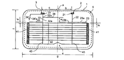
- FIG. 1 is a front view of an antenna pattern according to Embodiment 1 of the present invention as viewed from the vehicle exterior side.
- the antenna according to the first embodiment includes a pair of bus bars 41 disposed at the left and right ends of the rear glass 1 and a plurality of bus bars disposed between the pair of bus bars and both ends thereof connected to the bus bar. Arranged in the upper margin of the defogger 4 composed of the heating filament 42.
- the antenna of this embodiment is composed of a first antenna 2 and a second antenna 3.
- the first antenna power supply unit 21 and the second antenna power supply unit 31 are respectively disposed on the upper side of the rear glass 1 at positions spaced laterally.
- the first antenna 2 includes a first antenna power supply unit 21, a first antenna vertical line 22, and a first antenna horizontal line 23.
- the vertical line 22 of the first antenna has an upper end connected to the power feeding unit 21 of the first antenna, and a lower end connected to a middle part of the horizontal line 23 of the first antenna.
- the horizontal line 23 of the first antenna is disposed so as to be close to the uppermost heating horizontal line 42 of the defogger 4 and is capacitively coupled to the uppermost heating horizontal line 42.
- the second antenna 3 includes a feeding portion 31 of the second antenna, a vertical strip 32 of the second antenna, a horizontal strip 33 of the second antenna, and a first auxiliary strip 34 of the second antenna. It consists of and.
- the vertical line 32 of the second antenna has an upper end connected to the power feeding portion 31 of the second antenna, and a lower end connected to the right end of the horizontal line 33 of the second antenna.
- One end of the first auxiliary wire 34 of the second antenna is connected to a middle portion of the vertical wire 32 of the second antenna, and is horizontally extended in the right direction.
- the horizontal line 33 of the second antenna is disposed so as to be close to the uppermost heating horizontal line 42 of the defogger 4 and is capacitively coupled to the uppermost heating horizontal line 42.
- Rear glass 1 vertical width f 500 mm
- Rear glass 1 lateral width g 1300 mm
- the lateral distance b from the center line a of the rear glass 1 to the feeding portion 21 of the first antenna b 140 mm
- the lateral distance c from the center line a of the rear glass 1 to the feeding portion 31 of the second antenna c 140 mm
- the distance between the upper edge of the flange 5 and the feeding portion 21 of the first antenna 10 mm
- the distance between the upper edge of the flange 5 and the feeding portion 31 of the second antenna 10 mm
- Size of the feeding portion 21 of the first antenna: width X length 22 mm X 10 mm
- Length of vertical line 22 of the first antenna 60 mm
- the length of the horizontal line 23 of the first antenna 240 mm
- the length of the right side 23a from the connecting portion of the horizontal line 23 of the first antenna to the vertical line 22 of the first antenna 90 mm
- the outer conductor of the coaxial cable was grounded at a ground point where a coaxial cable extending from a tuner (not shown) was provided on the vehicle body in the vicinity of each feeding point, and the core wire side of the coaxial cable was connected to the AV line.
- FIG. 15 shows the average value of the reception sensitivity in all directions of the antennas of 76 MHz to 108 MHz in this embodiment, the solid line is the measurement result of the first antenna 2, and the broken line is the second antenna 3. It is a measurement result.
- FIG. 16 shows a directivity characteristic diagram regarding the reception sensitivity at 90 MHz of the antenna of the present embodiment.
- the solid line indicates the measurement result of the first antenna 2, and the broken line indicates the measurement result of the second antenna 3.
- FIG. 23 shows the average value of the reception sensitivity at each frequency of 76 MHz to 108 MHz of the antenna of Comparative Example 1 which is a comparative example of the present embodiment, and the solid line shows the measurement result of the first antenna 2.
- the broken line is the measurement result of the second antenna 3.
- FIG. 24 shows a directional characteristic diagram regarding the reception sensitivity at 90 MHz of the antenna of Comparative Example 1 which is a comparative example of the present embodiment.
- the solid line indicates the measurement result of the first antenna 2, and the broken line indicates the second result. It is a measurement result of the antenna 3.
- the antenna of the present example was able to perform diversity reception well in the frequency band outside Japan.
- Rear glass 1 vertical width f 500 mm
- Rear glass 1 lateral width g 1300 mm
- the lateral distance b from the center line a of the rear glass 1 to the feeding portion 21 of the first antenna b 140 mm
- the lateral distance c from the center line a of the rear glass 1 to the feeding portion 31 of the second antenna c 140 mm
- the distance between the upper edge of the flange 5 and the feeding portion 21 of the first antenna 10 mm
- the distance between the upper edge of the flange 5 and the feeding portion 31 of the second antenna 10 mm
- the length of the right side 23a from the connecting portion of the horizontal line 23 of the first antenna to the vertical line 22 of the first antenna 240 mm
- the outer conductor of the coaxial cable was grounded at a ground point where a coaxial cable extending from a tuner (not shown) was provided on the vehicle body in the vicinity of each feeding point, and the core wire side of the coaxial cable was connected to the AV line.
- FIG. 17 shows an average value of the reception sensitivity in each direction of 76 MHz to 108 MHz of the antenna of the present embodiment, the solid line is the measurement result of the first antenna 2, and the broken line is the second antenna 3. It is a measurement result.
- FIG. 18 shows a directivity characteristic diagram regarding the reception sensitivity at 78 MHz of the antenna of the present embodiment.
- the solid line indicates the measurement result of the first antenna 2, and the broken line indicates the measurement result of the second antenna 3.
- the directivity of the first antenna 2 has a large sensitivity on the left side
- the directivity of the second antenna 3 has a large sensitivity on the right side. It can be seen that the directivity characteristics are greatly different.
- the antenna of this example was able to perform diversity reception well in the domestic band.
- FIG. 2 is a front view of the antenna pattern according to the second embodiment of the present invention viewed from the outside of the vehicle.
- the lower end of the vertical strip 32 of the second antenna is connected to the middle portion of the horizontal strip 33 of the second antenna, and each of the first antenna 2 and the second antenna 3 is configured. Except for adjusting the length of the line and the connection position between the lines so that the input impedance of the first antenna 2 and the second antenna 3 can be matched between the feed line and the frequency band outside Japan.
- the configuration is the same as that of the antenna of the first embodiment.
- the antenna of the present example is printed on the rear glass 1 with a conductive ceramic paste so that the width of each filament is 0.7 mm, dried, and then baked in a heating furnace, An AV line is attached to each of the power feeding portions 31 of the second antenna and then attached to the vehicle body. Then, the outer conductor of the coaxial cable was grounded at a ground point where a coaxial cable extending from a tuner (not shown) was provided on the vehicle body in the vicinity of each feeding point, and the core wire side of the coaxial cable was connected to the AV line.
- the first antenna 2 and the second antenna 3 are different as in the first embodiment. Directional characteristics were obtained, and it was found that it was at a practical level.
- the first antenna 2 and the second antenna 3 are adjusted by adjusting the lengths of the wires constituting the first antenna 2 and the second antenna 3 of the present embodiment and the connecting positions of the wires. If the input impedance of the power supply line is matched with the characteristic impedance of the feeder line in the frequency band in Japan, as in the case where this embodiment is adjusted to the frequency band outside Japan, in the frequency band in Japan, With the antenna of this embodiment, the effect of diversity reception can be obtained.
- FIG. 3 is a front view of an antenna pattern according to the third embodiment of the present invention as viewed from the vehicle exterior side.
- the horizontal line 23 of the first antenna is connected to the lower end of the vertical line 22 of the first antenna at the left end, and is extended in the right direction.
- the first auxiliary wire 24 of the first antenna is connected to the middle portion of the strip 22, and the configuration differs from that of the first embodiment in that it extends in the left direction.
- the dimensions were as follows when it was adapted to be suitable for receiving FM bands outside Japan (88 MHz to 108 MHz).
- Rear glass 1 vertical width f 500 mm
- Rear glass 1 lateral width g 1300 mm
- the lateral distance b from the center line a of the rear glass 1 to the feeding portion 21 of the first antenna b 140 mm
- the lateral distance c from the center line a of the rear glass 1 to the feeding portion 31 of the second antenna c 140 mm
- the distance between the upper edge of the flange 5 and the feeding portion 21 of the first antenna 10 mm
- the distance between the upper edge of the flange 5 and the feeding portion 31 of the second antenna 10 mm
- the length of the lower side 22a of the vertical line 22 of the first antenna from the connecting portion of the first antenna with the first auxiliary line 24 of the first antenna 10 mm
- the outer conductor of the coaxial cable was grounded at a ground point where a coaxial cable extending from a tuner (not shown) was provided on the vehicle body in the vicinity of each feeding point, and the core wire side of the coaxial cable was connected to the AV line.
- FIG. 19 shows an average value of reception sensitivity in all directions of each frequency of 76 MHz to 108 MHz of the antenna of the present embodiment.
- the solid line indicates the measurement result of the first antenna 2 and the broken line indicates the second antenna 3. It is a measurement result.
- FIG. 20 shows a directional characteristic diagram for the reception sensitivity at 90 MHz of the antenna of the present embodiment, where the solid line is the measurement result of the first antenna 2 and the broken line is the measurement result of the second antenna 3.
- Example 25 and 26 include the antenna of Comparative Example 2 shown in FIG. 14 described later (the first auxiliary wire 24 of the first antenna and the first auxiliary wire 34 of the second antenna). This is a measurement result under the same measurement conditions as in Example 3) (antenna having a configuration different from that of Example 3).
- FIG. 25 shows the average value of the reception sensitivity at each frequency of 76 MHz to 108 MHz of the antenna of Comparative Example 2 which is a comparative example of the present embodiment, and the solid line shows the measurement result of the first antenna 2.
- the broken line is the measurement result of the second antenna 3.
- FIG. 26 shows a directivity characteristic diagram regarding the reception sensitivity at 90 MHz of the antenna of the comparative example 2 which is a comparative example of the present embodiment.
- the solid line indicates the measurement result of the first antenna 2, and the broken line indicates the second result. It is a measurement result of the antenna 3.
- the antenna of the present example was able to perform diversity reception well in the frequency band outside Japan.
- the distance e between the first auxiliary filament 24 of the first antenna and the first auxiliary filament 34 of the second antenna is 10 mm.
- the distance e is made smaller than 10 mm, the directivity characteristics of the reception sensitivities of the first antenna 2 and the second antenna 3 become similar, so that the distance e becomes 10 mm or more. It is preferable to constitute the antenna of the present invention.
- the first antenna 2 and the second antenna 3 are adjusted by adjusting the lengths of the wires constituting the first antenna 2 and the second antenna 3 of the present embodiment and the connecting positions of the wires. If the input impedance of the power supply line is matched with the characteristic impedance of the feeder line in the frequency band in Japan, as in the case where this embodiment is adjusted to the frequency band outside Japan, in the frequency band in Japan, With the antenna of this embodiment, the effect of diversity reception can be obtained.
- FIG. 4 is a front view of an antenna pattern according to Embodiment 4 of the present invention as viewed from the outside of the vehicle.
- the antenna of the fourth embodiment adjusts the configuration of the filaments that respectively configure the first antenna 2 and the second antenna in the first embodiment, and the characteristic impedance of the feeder line in the FM frequency band outside of Japan
- the first antenna 2 is moved to a position that is line-symmetric with respect to the center line a, and is newly set as the second antenna 3.
- the second antenna 3 is moved to a position that is line symmetric with respect to the center line a, so that the first antenna 2 is newly formed.
- the antenna of the present example is printed on the rear glass 1 with a conductive ceramic paste so that the width of each filament is 0.7 mm, dried, and then baked in a heating furnace, An AV line is attached to each of the power feeding portions 31 of the second antenna and then attached to the vehicle body. Then, the outer conductor of the coaxial cable was grounded at a ground point where a coaxial cable extending from a tuner (not shown) was provided on the vehicle body in the vicinity of each feeding point, and the core wire side of the coaxial cable was connected to the AV line.
- the first antenna 2 and the second antenna 3 were similar to the first example. It was found that different directivity characteristics were obtained and it was at a practical level.
- the directivity characteristic of the first antenna 2 of the present embodiment is obtained by inverting the directivity characteristic regarding the reception sensitivity of the second antenna 3 of the first embodiment to the left and right, and the second antenna of the present embodiment.
- the directional characteristics of 3 are obtained by inverting the directional characteristics of the reception sensitivity of the first antenna 2 of Example 1 to the left and right.
- the configuration of the filaments constituting the first antenna 2 and the second antenna 3 in the FM frequency band in Japan in the first embodiment is adjusted, and the input of the two antennas is adjusted. Even when the impedance and the characteristic impedance of the feeder line are matched, when the two antennas are moved to positions that are symmetric with respect to the center line a as in this embodiment, Similar to the case where the present embodiment is adjusted to the frequency band outside Japan, the antenna of the present embodiment can achieve the effect of diversity reception in the frequency band in Japan.
- FIG. 5 is a front view of an antenna pattern according to Embodiment 5 of the present invention as viewed from the vehicle outer side.
- the horizontal line 33 of the second antenna has its left end connected to the lower end of the vertical line 32 of the second antenna and is extended in the right direction.
- the vertical line of the second antenna The first auxiliary wire 34 of the second antenna connected to the middle portion of the strip 32 extends leftward, and the first antenna first wire 34 extends to the middle portion of the vertical strip 22 of the first antenna.
- the auxiliary wire 24 is connected and extended in the right direction, and the length of each wire constituting each of the first antenna 2 and the second antenna 3 and the connection position of each wire are adjusted, Except that the input impedance of the antenna 2 and the second antenna 3 is matched with the characteristic impedance of the feeder line in the FM frequency band outside Japan, the configuration is the same as that of the antenna of the first embodiment.
- the antenna of the present example is printed on the rear glass 1 with a conductive ceramic paste so that the width of each filament is 0.7 mm, dried, and then baked in a heating furnace, An AV line is attached to each of the power feeding portions 31 of the second antenna and then attached to the vehicle body. Then, the outer conductor of the coaxial cable was grounded at a ground point where a coaxial cable extending from a tuner (not shown) was provided on the vehicle body in the vicinity of each feeding point, and the core wire side of the coaxial cable was connected to the AV line.
- the first antenna 2 and the second antenna 3 are different as in the first embodiment. Directional characteristics were obtained, and it was found that it was at a practical level.
- the first antenna 2 and the second antenna 3 are adjusted by adjusting the lengths of the wires constituting the first antenna 2 and the second antenna 3 of the present embodiment and the connecting positions of the wires. If the input impedance is matched with the characteristic impedance of the feeder in the frequency band in Japan, the frequency band in Japan is the same as in the case of adjusting the present embodiment to the frequency band outside Japan. With the antenna of the embodiment, the effect of diversity reception can be obtained.
- FIG. 6 is a front view of an antenna pattern according to Embodiment 6 of the present invention as viewed from the vehicle outer side.
- the antenna of the sixth embodiment is the second auxiliary line 34 of the second antenna at the same connection position as the first auxiliary line 34 of the second antenna in the middle of the vertical line 32 of the second antenna. 'Is added and extended to the left side, and the length of the filaments constituting each of the first antenna 2 and the second antenna 3 and the connection position between the filaments are adjusted, and the first antenna 2 and the second antenna 2
- the antenna 3 has the same configuration as that of the antenna of Example 1 except that the input impedance of the antenna 3 is matched with the characteristic impedance of the feeder line in the FM frequency band outside Japan.
- the antenna of the present example is printed on the rear glass 1 with a conductive ceramic paste so that the width of each filament is 0.7 mm, dried, and then baked in a heating furnace, An AV line is attached to each of the power feeding portions 31 of the second antenna and then attached to the vehicle body. Then, the outer conductor of the coaxial cable was grounded at a ground point where a coaxial cable extending from a tuner (not shown) was provided on the vehicle body in the vicinity of each feeding point, and the core wire side of the coaxial cable was connected to the AV line.
- the first antenna 2 and the second antenna 3 are different as in the first embodiment. Directional characteristics were obtained, and it was found that it was at a practical level.
- the first antenna 2 and the second antenna 3 are adjusted by adjusting the lengths of the wires constituting the first antenna 2 and the second antenna 3 of the present embodiment and the connecting positions of the wires. If the input impedance is matched with the characteristic impedance of the feeder in the frequency band in Japan, the frequency band in Japan is the same as in the case of adjusting the present embodiment to the frequency band outside Japan. With the antenna of the embodiment, the effect of diversity reception can be obtained.
- FIG. 7 is the front view seen from the vehicle outer side of the antenna pattern which concerns on Example 7 of this invention.
- the antenna of Example 7 is connected to the connection position of the second auxiliary wire 34 ′ of the second antenna connected to the middle portion of the vertical wire 32 of the second antenna and the vertical wire 32 of the second antenna.
- the connection position of the first auxiliary wire 34 of the connected second antenna is not the same place but a different place, so that the wire constituting each of the first antenna 2 and the second antenna 3
- the input impedances of the first antenna 2 and the second antenna 3 are connected to the power feeding unit 21 of the first antenna and the power feeding unit 31 of the second antenna by adjusting the length and the connection position of the filaments.
- the configuration is the same as that of the antenna of the sixth embodiment except that the characteristic impedance of the feeder line is matched with the FM frequency band outside Japan.
- the antenna of the present example is printed on the rear glass 1 with a conductive ceramic paste so that the width of each filament is 0.7 mm, dried, and then baked in a heating furnace, An AV line is attached to each of the power feeding portions 31 of the second antenna and then attached to the vehicle body. Then, the outer conductor of the coaxial cable was grounded at a ground point where a coaxial cable extending from a tuner (not shown) was provided on the vehicle body in the vicinity of each feeding point, and the core wire side of the coaxial cable was connected to the AV line.
- the first antenna 2 and the second antenna 3 are different as in the first embodiment. Directional characteristics were obtained, and it was found that it was at a practical level.
- the first antenna 2 and the second antenna 3 are adjusted by adjusting the lengths of the wires constituting the first antenna 2 and the second antenna 3 of the present embodiment and the connecting positions of the wires. If the input impedance of the power supply line is matched with the characteristic impedance of the feeder line in the frequency band in Japan, as in the case where this embodiment is adjusted to the frequency band outside Japan, in the frequency band in Japan, With the antenna of this embodiment, the effect of diversity reception can be obtained.
- FIG. 8 is a front view of an antenna pattern according to the eighth embodiment of the present invention as viewed from the vehicle outer side.
- the second auxiliary line 34 ′ of the second antenna is connected to the left end of the horizontal line 33 of the second antenna, and the second auxiliary line 34 ′ of the second antenna is connected to the second antenna.
- Bending part 34'a of the 2nd auxiliary filament of the 2nd antenna is formed in the middle, the length of the filament which constitutes each of the 1st antenna 2 and the 2nd antenna 3, and
- the input impedances of the first antenna 2 and the second antenna 3 are connected to the power feeding unit 21 of the first antenna and the power feeding unit 31 of the second antenna.
- the configuration is the same as that of the antenna of the first embodiment except that the characteristic impedance is matched with the FM frequency band outside Japan.
- the antenna of the present example is printed on the rear glass 1 with a conductive ceramic paste so that the width of each filament is 0.7 mm, dried, and then baked in a heating furnace, An AV line is attached to each of the power feeding portions 31 of the second antenna and then attached to the vehicle body. Then, the outer conductor of the coaxial cable was grounded at a ground point where a coaxial cable extending from a tuner (not shown) was provided on the vehicle body in the vicinity of each feeding point, and the core wire side of the coaxial cable was connected to the AV line.
- the first antenna 2 and the second antenna 3 are different as in the first embodiment. Directional characteristics were obtained, and it was found that it was at a practical level.
- the first antenna 2 and the second antenna 3 are adjusted by adjusting the lengths of the wires constituting the first antenna 2 and the second antenna 3 of the present embodiment and the connecting positions of the wires. If the input impedance of the power supply line is matched with the characteristic impedance of the feeder line in the frequency band in Japan, as in the case where this embodiment is adjusted to the frequency band outside Japan, in the frequency band in Japan, With the antenna of this embodiment, the effect of diversity reception can be obtained.
- FIG. 9 is a front view of an antenna pattern according to the ninth embodiment of the present invention viewed from the vehicle outer side.
- the right end of the second auxiliary line 34 ′ of the second antenna is connected to the power feeding portion 31 of the second antenna, is extended to the left side, and is bent in the middle of the second antenna.
- the second auxiliary wire bend 34'a is formed, and the length of the wire constituting each of the first antenna 2 and the second antenna 3 and the connection position between the wires are adjusted.
- the input impedance of the first antenna 2 and the second antenna 3 is changed to the characteristic impedance of the feed line connected to the feed unit 21 of the first antenna and the feed unit 31 of the second antenna and the FM frequency outside Japan.
- the configuration is the same as that of the antenna according to the first embodiment except that the band is matched.
- the antenna of the present example is printed on the rear glass 1 with a conductive ceramic paste so that the width of each filament is 0.7 mm, dried, and then baked in a heating furnace, An AV line is attached to each of the power feeding portions 31 of the second antenna and then attached to the vehicle body. Then, the outer conductor of the coaxial cable was grounded at a ground point where a coaxial cable extending from a tuner (not shown) was provided on the vehicle body in the vicinity of each feeding point, and the core wire side of the coaxial cable was connected to the AV line.
- the first antenna 2 and the second antenna 3 are different as in the first embodiment. Directional characteristics were obtained, and it was found that it was at a practical level.
- the first antenna 2 and the second antenna 3 are adjusted by adjusting the lengths of the wires constituting the first antenna 2 and the second antenna 3 of the present embodiment and the connecting positions of the wires. If the input impedance of the power supply line is matched with the characteristic impedance of the feeder line in the frequency band in Japan, as in the case where this embodiment is adjusted to the frequency band outside Japan, in the frequency band in Japan, With the antenna of this embodiment, the effect of diversity reception can be obtained.
- FIG. 10 is a front view of an antenna pattern according to Example 10 of the present invention viewed from the vehicle exterior side.
- the left end of the feeding line 211 of the first antenna and the feeding of the second antenna are respectively connected to the upper ends of the vertical strip 22 of the first antenna and the vertical strip 32 of the second antenna.
- the right end of the wire strip 311 is connected, extended to the right side and the left side, respectively, the feed section 21 is connected to the right end of the feed line strip 211 of the first antenna, and the second end is connected to the left end of the feed line strip 311 of the second antenna.
- the first and second antennas 2 and 2 are connected to each other by adjusting the lengths of the wires constituting the first antenna 2 and the second antenna 3 and the connecting positions of the wires. Except that the input impedance of the antenna 3 is matched with the characteristic impedance of the feeder connected to the feeder 21 of the first antenna and the feeder 31 of the second antenna in the FM frequency band outside Japan. ,Example The same configuration as that of the antenna.
- the antenna of the present example is printed on the rear glass 1 with a conductive ceramic paste so that the width of each filament is 0.7 mm, dried, and then baked in a heating furnace, An AV line is attached to each of the power feeding portions 31 of the second antenna and then attached to the vehicle body. Then, the outer conductor of the coaxial cable was grounded at a ground point where a coaxial cable extending from a tuner (not shown) was provided on the vehicle body in the vicinity of each feeding point, and the core wire side of the coaxial cable was connected to the AV line.
- the first antenna 2 and the second antenna 3 are different as in the first embodiment. Directional characteristics were obtained, and it was found that it was at a practical level.
- the first antenna 2 and the second antenna 3 are adjusted by adjusting the lengths of the wires constituting the first antenna 2 and the second antenna 3 of the present embodiment and the connecting positions of the wires. If the input impedance of the power supply line is matched with the characteristic impedance of the feeder line in the frequency band in Japan, as in the case where this embodiment is adjusted to the frequency band outside Japan, in the frequency band in Japan, With the antenna of this embodiment, the effect of diversity reception can be obtained.
- FIG. 11 is the front view seen from the vehicle outer side of the antenna pattern which concerns on Example 11 of this invention.
- the right end of the first antenna feed line 211 and the second antenna feed are respectively provided at the upper ends of the first antenna vertical line 22 and the second antenna vertical line 32.
- the left end of the wire strip 311 is connected, extended to the left and right sides, respectively, the power feeding section 21 is connected to the left end of the power feed strip 211 of the first antenna, and the second end is connected to the right end of the power feed strip 311 of the second antenna.
- the first and second antennas 2 and 2 are connected to each other by adjusting the lengths of the wires constituting the first antenna 2 and the second antenna 3 and the connecting positions of the wires. Except that the input impedance of the antenna 3 is matched with the characteristic impedance of the feeder connected to the feeder 21 of the first antenna and the feeder 31 of the second antenna in the FM frequency band outside Japan. ,Example The same configuration as that of the antenna.
- the antenna of the present example is printed on the rear glass 1 with a conductive ceramic paste so that the width of each filament is 0.7 mm, dried, and then baked in a heating furnace, An AV line is attached to each of the power feeding portions 31 of the second antenna and then attached to the vehicle body. Then, the outer conductor of the coaxial cable was grounded at a ground point where a coaxial cable extending from a tuner (not shown) was provided on the vehicle body in the vicinity of each feeding point, and the core wire side of the coaxial cable was connected to the AV line.
- the first antenna 2 and the second antenna 3 are different as in the first embodiment. Directional characteristics were obtained, and it was found that it was at a practical level.
- the first antenna 2 and the second antenna 3 are adjusted by adjusting the lengths of the wires constituting the first antenna 2 and the second antenna 3 of the present embodiment and the connecting positions of the wires. If the input impedance of the power supply line is matched with the characteristic impedance of the feeder line in the frequency band in Japan, as in the case where this embodiment is adjusted to the frequency band outside Japan, in the frequency band in Japan, With the antenna of this embodiment, the effect of diversity reception can be obtained.
- FIG. 27 shows a side view and a rear view of the automobile 6 when the rear glass 1 provided with the antenna pattern according to the first embodiment of the present invention is attached to the rear gate 64 of the wagon type automobile 6. .
- FM broadcast waves are diversity-received by the first antenna 2 and the second antenna 3 that are the antennas according to the first embodiment of the present invention, and the AM broadcast waves for the side glass printed on the side glass 63 are received.
- the AM antenna wave is received by the glass antenna 7 for use.
- the first antenna 2 and the second antenna 3, which are antennas according to the first embodiment of the present invention, and the AM broadcast wave glass antenna 7 for the side glass are respectively connected to separate feed lines, and each feed line is an automobile. 6 is connected to a receiver (not shown).
- the side glass AM broadcast wave glass antenna 7 is provided at the feed point 71 of the side glass AM broadcast wave glass antenna and the side glass AM broadcast wave glass antenna. It is comprised from the filament part 72 of the glass antenna for AM broadcast waves for the side glass connected.
- an AM broadcast wave glass antenna for a side glass that is generally used for a side glass of an automobile can be used.
- the AM broadcast wave antenna and the FM broadcast wave antenna can all be formed of glass antennas, and the design of the automobile can be improved.
- FIG. 28 also shows a side view and a rear view of the automobile 6 when the rear glass 1 provided with the antenna pattern according to the first embodiment of the present invention is attached to the rear gate 64 of the wagon type automobile 6. .
- the AM broadcast wave is different from that of the twelfth embodiment in that the AM broadcast wave is received by an AM broadcast wave antenna (not shown) built in the rear spoiler 65.
- the first antenna 2 and the second antenna 3 that are the antennas according to the first embodiment of the present invention and the AM broadcast wave antenna (not shown) built in the rear spoiler 65 are connected to separate feeding lines. Each feeder line is connected to a receiver (not shown) provided in the automobile 6.
- AM broadcast wave antenna (not shown) built in the rear spoiler 65, one that is generally used in automobiles can be used.
- This configuration makes it possible to receive not only FM broadcast waves but also AM broadcast waves.
- Example 13 the antenna built in the rear spoiler 65 was used as the AM broadcast wave antenna.
- the AM broadcast wave antenna does not need to be built in the rear spoiler 65, and is built in a bumper of an automobile. It can be arranged at various places such as at the bottom of an automobile or at the roof of an automobile.
- FIG. 12 is a front view of an antenna pattern according to a reference example of the present invention as viewed from the vehicle outer side.
- the antenna of the present reference example is obtained by removing the second antenna 3 from the antennas of the first embodiment and leaving only the first antenna 2.
- the dimensions of the first antenna 2 of the present reference example are as follows.
- the dimensions of the first antenna 2 and the dimensions of the first antenna 2 in Comparative Example 1 are the same as in Example 1 when matched to the FM frequency band outside Japan. That is, the dimensions are as follows.
- Rear glass 1 vertical width f 500 mm
- Rear glass 1 lateral width g 1300 mm
- the lateral distance b from the center line a of the rear glass 1 to the feeding portion 21 of the first antenna b 140 mm
- the distance between the upper edge of the flange 5 and the feeding portion 21 of the first antenna 10 mm
- Size of the feeding portion 21 of the first antenna: width X length 22 mm X 10 mm
- Length of vertical line 22 of the first antenna 60 mm
- the length of the horizontal line 23 of the first antenna 240 mm
- the length of the right side 23a from the connecting portion of the horizontal line 23 of the first antenna to the vertical line 22 of the first antenna 90 mm
- the length of the left side 23b from the connecting portion of the horizontal line 23 of the first antenna to the vertical line 22 of the first antenna 150 mm
- the distance d 10 mm between the heating horizontal filament 42 at the top of the defogger 4 and the horizontal filament 23 of the first antenna
- FIG. 21 shows an average value of the reception sensitivity in each direction of the frequency of 76 MHz to 108 MHz of the antenna of this reference example, and the solid line is the measurement result of the first antenna 2.
- FIG. 22 shows a directional characteristic diagram of the reception sensitivity at 90 MHz of the antenna of this reference example, and the solid line is the measurement result of the first antenna 2.
- the average value of the reception sensitivity in the 88 MHz to 108 MHz in the outer band of Japan of this reference example in FIG. 21 is the first indicated by the solid line when the dimensions are matched to the outer band of Japan in Example 1 in FIG. It can be seen that the value is larger than the measurement result related to the antenna 2 of FIG.
- the directivity characteristics are depressed at two locations indicated by arrows, and when the antenna dimensions are adjusted to the outer band of Japan in Example 1 in FIG.
- the measurement results for the first antenna 2 indicated by the solid line and the measurement results for the first antenna 2 indicated by the solid line of Comparative Example 1 in FIG. It can be seen that the directivity characteristic regarding the reception sensitivity is substantially the same as the directivity characteristic regarding the reception sensitivity of the first antenna 2 of the first comparative example 1 shown in FIG.
- the first antenna 2 of the present reference example is further provided with the second antenna feeding portion 31, the second antenna vertical stripe 32, and the second antenna horizontal stripe. If only the second antenna 3 composed of only 33 is added, when receiving FM broadcast waves with two antennas, the antenna is compared with the case of receiving with one antenna as in this reference example. As a result, there is a concern that the reception performance will deteriorate.
- FIG. 13 is a front view of the antenna pattern of Comparative Example 1, which is a comparative example according to Example 1 of the present invention, as viewed from the vehicle exterior side.
- the antenna of this comparative example is obtained by removing the first auxiliary filament 34 of the second antenna from the second antenna 3 of the antennas of the first embodiment whose dimensions are adjusted to the band outside Japan. This is the same as the antenna of the first embodiment. That is, the dimensions are as follows.
- Rear glass 1 vertical width f 500 mm
- Rear glass 1 lateral width g 1300 mm
- the lateral distance b from the center line a of the rear glass 1 to the feeding portion 21 of the first antenna b 140 mm
- the lateral distance c from the center line b of the rear glass 1 to the feeding portion 31 of the second antenna c 140 mm
- the distance between the upper edge of the flange 5 and the feeding portion 21 of the first antenna 10 mm
- the distance between the upper edge of the flange 5 and the feeding portion 31 of the second antenna 10 mm
- Size of the feeding portion 21 of the first antenna: width X length 22 mm X 10 mm
- Length of vertical line 22 of the first antenna 60 mm
- the length of the horizontal line 23 of the first antenna 240 mm
- the length of the right side 23a from the connecting portion of the horizontal line 23 of the first antenna to the vertical line 22 of the first antenna 90 mm
- FIG. 23 shows the average value of the reception sensitivity in all directions of the antennas of 76 MHz to 108 MHz of the antenna of this embodiment.
- the solid line indicates the measurement result of the first antenna 2 and the broken line indicates the second antenna 3. It is a measurement result.
- FIG. 24 shows a directional characteristic diagram for the reception sensitivity at 90 MHz of the antenna of the present embodiment, where the solid line is the measurement result of the first antenna 2 and the broken line is the measurement result of the second antenna 3.
- the directivity characteristic regarding the reception sensitivity of the first antenna 2 and the directivity characteristic regarding the reception sensitivity of the second antenna 3 are similar to each other. It can be understood that when neither the second antenna 3 nor the second antenna 3 has the auxiliary filament, good diversity reception with respect to the FM broadcast wave cannot be performed.
- FIG. 14 is a front view of the antenna pattern of Comparative Example 2, which is a comparative example according to Example 3 of the present invention, as viewed from the vehicle exterior side.
- the first auxiliary wire 24 of the first antenna is removed from the first antenna 2 of the antennas of the third embodiment, and the first antenna of the second antenna 3 is further removed from the second antenna 3.
- the auxiliary wire 34 is removed, and the other points are the same as those of the antenna of the third embodiment. That is, the dimensions are as follows.
- Rear glass 1 vertical width f 500 mm
- Rear glass 1 lateral width g 1300 mm
- the lateral distance b from the center line a of the rear glass 1 to the feeding portion 21 of the first antenna b 140 mm
- the lateral distance c from the center line b of the rear glass 1 to the feeding portion 31 of the second antenna c 140 mm
- the distance between the upper edge of the flange 5 and the feeding portion 21 of the first antenna 10 mm
- the distance between the upper edge of the flange 5 and the feeding portion 31 of the second antenna 10 mm
- FIG. 25 shows the average value of the reception sensitivity in all directions of the antennas of 76 MHz to 108 MHz in this embodiment, the solid line is the measurement result of the first antenna 2, and the broken line is the second antenna 3. It is a measurement result.
- FIG. 26 shows a directional characteristic diagram for the reception sensitivity at 90 MHz of the antenna of the present embodiment.
- the solid line indicates the measurement result of the first antenna 2, and the broken line indicates the measurement result of the second antenna 3.
- FIG. 26 shows that the directivity characteristic for the reception sensitivity of the first antenna 2 and the directivity characteristic for the reception sensitivity of the second antenna 3 are similar to each other. It can be understood that when neither the second antenna 3 nor the second antenna 3 has the auxiliary filament, good diversity reception with respect to the FM broadcast wave cannot be performed.
Landscapes
- Details Of Aerials (AREA)
- Variable-Direction Aerials And Aerial Arrays (AREA)
Abstract
L'invention vise à procurer une antenne de vitre de véhicule, dans laquelle une onde de radiodiffusion à modulation de fréquence peut être reçue en diversité de façon favorable par la disposition de deux antennes dans un espace au-dessus d'un désembueur de la lunette arrière du véhicule même lorsque l'espace est étroit. A cet effet, l'invention porte sur une antenne de vitre de véhicule, laquelle antenne comprend deux antennes d'ondes de radiodiffusion à modulation de fréquence disposées dans un espace au-dessus d'un désembueur de la lunette arrière du véhicule, et chacune des antennes comporte une unité d'alimentation disposée séparément vis-à-vis de l'autre sur le côté gauche/droit à l'extrémité supérieure de la lunette arrière, une ligne verticale connectée à ladite unité d'alimentation et s'étendant vers le bas, et une ligne horizontale connectée à l'extrémité inférieure de ladite ligne verticale. Lesdites lignes horizontales respectives comprises dans lesdites deux antennes sont disposées au voisinage de la ligne horizontale chauffante la plus haute dans ledit désembueur, de sorte que les lignes horizontales soient couplées de façon capacitive à ladite ligne horizontale chauffante la plus haute. Au moins une ligne auxiliaire pour régler des caractéristiques directionnelles est connectée à ladite ligne verticale ou à ladite unité d'alimentation dans au moins une antenne parmi lesdites deux antennes.
Applications Claiming Priority (2)
| Application Number | Priority Date | Filing Date | Title |
|---|---|---|---|
| JP2011117670A JP2012248981A (ja) | 2011-05-26 | 2011-05-26 | 車両用ガラスアンテナ |
| JP2011-117670 | 2011-05-26 |
Publications (1)
| Publication Number | Publication Date |
|---|---|
| WO2012160991A1 true WO2012160991A1 (fr) | 2012-11-29 |
Family
ID=47217071
Family Applications (1)
| Application Number | Title | Priority Date | Filing Date |
|---|---|---|---|
| PCT/JP2012/062095 Ceased WO2012160991A1 (fr) | 2011-05-26 | 2012-05-11 | Antenne de vitre de véhicule |
Country Status (2)
| Country | Link |
|---|---|
| JP (1) | JP2012248981A (fr) |
| WO (1) | WO2012160991A1 (fr) |
Cited By (1)
| Publication number | Priority date | Publication date | Assignee | Title |
|---|---|---|---|---|
| CN109149077A (zh) * | 2017-06-27 | 2019-01-04 | Agc株式会社 | 玻璃天线和车辆用窗玻璃 |
Families Citing this family (3)
| Publication number | Priority date | Publication date | Assignee | Title |
|---|---|---|---|---|
| JP6379504B2 (ja) * | 2014-02-07 | 2018-08-29 | セントラル硝子株式会社 | ガラスアンテナ |
| JP6863697B2 (ja) * | 2015-10-29 | 2021-04-21 | 日本板硝子株式会社 | 車両用窓ガラス |
| JP2025031401A (ja) | 2023-08-25 | 2025-03-07 | 日本板硝子株式会社 | 車両用ガラスアンテナ |
Citations (3)
| Publication number | Priority date | Publication date | Assignee | Title |
|---|---|---|---|---|
| JP2000059124A (ja) * | 1998-06-03 | 2000-02-25 | Nippon Sheet Glass Co Ltd | 自動車用ガラスアンテナ装置 |
| JP2008022430A (ja) * | 2006-07-14 | 2008-01-31 | Nippon Antenna Co Ltd | 車載用アンテナ装置 |
| JP2010109958A (ja) * | 2008-10-02 | 2010-05-13 | Central Glass Co Ltd | 車両用のガラスアンテナ |
-
2011
- 2011-05-26 JP JP2011117670A patent/JP2012248981A/ja not_active Withdrawn
-
2012
- 2012-05-11 WO PCT/JP2012/062095 patent/WO2012160991A1/fr not_active Ceased
Patent Citations (3)
| Publication number | Priority date | Publication date | Assignee | Title |
|---|---|---|---|---|
| JP2000059124A (ja) * | 1998-06-03 | 2000-02-25 | Nippon Sheet Glass Co Ltd | 自動車用ガラスアンテナ装置 |
| JP2008022430A (ja) * | 2006-07-14 | 2008-01-31 | Nippon Antenna Co Ltd | 車載用アンテナ装置 |
| JP2010109958A (ja) * | 2008-10-02 | 2010-05-13 | Central Glass Co Ltd | 車両用のガラスアンテナ |
Cited By (2)
| Publication number | Priority date | Publication date | Assignee | Title |
|---|---|---|---|---|
| CN109149077A (zh) * | 2017-06-27 | 2019-01-04 | Agc株式会社 | 玻璃天线和车辆用窗玻璃 |
| CN109149077B (zh) * | 2017-06-27 | 2021-10-22 | Agc株式会社 | 玻璃天线和车辆用窗玻璃 |
Also Published As
| Publication number | Publication date |
|---|---|
| JP2012248981A (ja) | 2012-12-13 |
Similar Documents
| Publication | Publication Date | Title |
|---|---|---|
| JP5428847B2 (ja) | 自動車用のガラスアンテナ | |
| JP4941171B2 (ja) | 車両用ガラスアンテナ | |
| JP5299276B2 (ja) | 自動車用高周波ガラスアンテナ | |
| JP5339710B2 (ja) | 自動車用のガラスアンテナ | |
| JP4941158B2 (ja) | 車両用ガラスアンテナ | |
| JP6094334B2 (ja) | 車両用ガラスアンテナ | |
| JP6413429B2 (ja) | ガラスアンテナ及びバックドア | |
| JPWO2015137108A1 (ja) | 自動車用ガラスアンテナ | |
| JP6221779B2 (ja) | ガラスアンテナ | |
| JP6123457B2 (ja) | 自動車用ガラスアンテナ | |
| JP2016043842A (ja) | バックドア | |
| JP5671971B2 (ja) | 車両用アンテナ | |
| WO2012160991A1 (fr) | Antenne de vitre de véhicule | |
| JP2009164678A (ja) | 車両用ガラスアンテナ | |
| JP5387317B2 (ja) | 車両用ガラスアンテナ | |
| JP5338377B2 (ja) | ガラスアンテナ | |
| JP5742509B2 (ja) | 車両用ガラスアンテナ | |
| KR101340742B1 (ko) | 차량용 유리 안테나 | |
| JP5332895B2 (ja) | 車両用ガラスアンテナ | |
| JP2023023135A (ja) | 車両用窓ガラス | |
| JP5316230B2 (ja) | ガラスアンテナ | |
| JP6601312B2 (ja) | 車両用ガラスアンテナ及び該車両用ガラスアンテナを備える後部窓ガラス | |
| JP2016058946A (ja) | 自動車用ガラスアンテナ | |
| JP5532942B2 (ja) | ガラスアンテナ |
Legal Events
| Date | Code | Title | Description |
|---|---|---|---|
| 121 | Ep: the epo has been informed by wipo that ep was designated in this application |
Ref document number: 12789942 Country of ref document: EP Kind code of ref document: A1 |
|
| NENP | Non-entry into the national phase |
Ref country code: DE |
|
| 122 | Ep: pct application non-entry in european phase |
Ref document number: 12789942 Country of ref document: EP Kind code of ref document: A1 |