WO2012161016A1 - Simulateur de course, maître-cylindre équipé d'un simulateur de course et système de frein utilisant un maître-cylindre - Google Patents
Simulateur de course, maître-cylindre équipé d'un simulateur de course et système de frein utilisant un maître-cylindre Download PDFInfo
- Publication number
- WO2012161016A1 WO2012161016A1 PCT/JP2012/062303 JP2012062303W WO2012161016A1 WO 2012161016 A1 WO2012161016 A1 WO 2012161016A1 JP 2012062303 W JP2012062303 W JP 2012062303W WO 2012161016 A1 WO2012161016 A1 WO 2012161016A1
- Authority
- WO
- WIPO (PCT)
- Prior art keywords
- stroke
- simulator
- input shaft
- hydraulic pressure
- brake
- Prior art date
- Legal status (The legal status is an assumption and is not a legal conclusion. Google has not performed a legal analysis and makes no representation as to the accuracy of the status listed.)
- Ceased
Links
Images


Classifications
-
- B—PERFORMING OPERATIONS; TRANSPORTING
- B60—VEHICLES IN GENERAL
- B60T—VEHICLE BRAKE CONTROL SYSTEMS OR PARTS THEREOF; BRAKE CONTROL SYSTEMS OR PARTS THEREOF, IN GENERAL; ARRANGEMENT OF BRAKING ELEMENTS ON VEHICLES IN GENERAL; PORTABLE DEVICES FOR PREVENTING UNWANTED MOVEMENT OF VEHICLES; VEHICLE MODIFICATIONS TO FACILITATE COOLING OF BRAKES
- B60T13/00—Transmitting braking action from initiating means to ultimate brake actuator with power assistance or drive; Brake systems incorporating such transmitting means, e.g. air-pressure brake systems
- B60T13/10—Transmitting braking action from initiating means to ultimate brake actuator with power assistance or drive; Brake systems incorporating such transmitting means, e.g. air-pressure brake systems with fluid assistance, drive, or release
- B60T13/12—Transmitting braking action from initiating means to ultimate brake actuator with power assistance or drive; Brake systems incorporating such transmitting means, e.g. air-pressure brake systems with fluid assistance, drive, or release the fluid being liquid
- B60T13/14—Transmitting braking action from initiating means to ultimate brake actuator with power assistance or drive; Brake systems incorporating such transmitting means, e.g. air-pressure brake systems with fluid assistance, drive, or release the fluid being liquid using accumulators or reservoirs fed by pumps
- B60T13/142—Systems with master cylinder
- B60T13/145—Master cylinder integrated or hydraulically coupled with booster
- B60T13/146—Part of the system directly actuated by booster pressure
-
- B—PERFORMING OPERATIONS; TRANSPORTING
- B60—VEHICLES IN GENERAL
- B60T—VEHICLE BRAKE CONTROL SYSTEMS OR PARTS THEREOF; BRAKE CONTROL SYSTEMS OR PARTS THEREOF, IN GENERAL; ARRANGEMENT OF BRAKING ELEMENTS ON VEHICLES IN GENERAL; PORTABLE DEVICES FOR PREVENTING UNWANTED MOVEMENT OF VEHICLES; VEHICLE MODIFICATIONS TO FACILITATE COOLING OF BRAKES
- B60T11/00—Transmitting braking action from initiating means to ultimate brake actuator without power assistance or drive or where such assistance or drive is irrelevant
- B60T11/10—Transmitting braking action from initiating means to ultimate brake actuator without power assistance or drive or where such assistance or drive is irrelevant transmitting by fluid means, e.g. hydraulic
- B60T11/16—Master control, e.g. master cylinders
- B60T11/20—Tandem, side-by-side, or other multiple master cylinder units
-
- B—PERFORMING OPERATIONS; TRANSPORTING
- B60—VEHICLES IN GENERAL
- B60T—VEHICLE BRAKE CONTROL SYSTEMS OR PARTS THEREOF; BRAKE CONTROL SYSTEMS OR PARTS THEREOF, IN GENERAL; ARRANGEMENT OF BRAKING ELEMENTS ON VEHICLES IN GENERAL; PORTABLE DEVICES FOR PREVENTING UNWANTED MOVEMENT OF VEHICLES; VEHICLE MODIFICATIONS TO FACILITATE COOLING OF BRAKES
- B60T13/00—Transmitting braking action from initiating means to ultimate brake actuator with power assistance or drive; Brake systems incorporating such transmitting means, e.g. air-pressure brake systems
- B60T13/10—Transmitting braking action from initiating means to ultimate brake actuator with power assistance or drive; Brake systems incorporating such transmitting means, e.g. air-pressure brake systems with fluid assistance, drive, or release
- B60T13/66—Electrical control in fluid-pressure brake systems
- B60T13/662—Electrical control in fluid-pressure brake systems characterised by specified functions of the control system components
-
- B—PERFORMING OPERATIONS; TRANSPORTING
- B60—VEHICLES IN GENERAL
- B60T—VEHICLE BRAKE CONTROL SYSTEMS OR PARTS THEREOF; BRAKE CONTROL SYSTEMS OR PARTS THEREOF, IN GENERAL; ARRANGEMENT OF BRAKING ELEMENTS ON VEHICLES IN GENERAL; PORTABLE DEVICES FOR PREVENTING UNWANTED MOVEMENT OF VEHICLES; VEHICLE MODIFICATIONS TO FACILITATE COOLING OF BRAKES
- B60T13/00—Transmitting braking action from initiating means to ultimate brake actuator with power assistance or drive; Brake systems incorporating such transmitting means, e.g. air-pressure brake systems
- B60T13/10—Transmitting braking action from initiating means to ultimate brake actuator with power assistance or drive; Brake systems incorporating such transmitting means, e.g. air-pressure brake systems with fluid assistance, drive, or release
- B60T13/66—Electrical control in fluid-pressure brake systems
- B60T13/68—Electrical control in fluid-pressure brake systems by electrically-controlled valves
- B60T13/686—Electrical control in fluid-pressure brake systems by electrically-controlled valves in hydraulic systems or parts thereof
-
- B—PERFORMING OPERATIONS; TRANSPORTING
- B60—VEHICLES IN GENERAL
- B60T—VEHICLE BRAKE CONTROL SYSTEMS OR PARTS THEREOF; BRAKE CONTROL SYSTEMS OR PARTS THEREOF, IN GENERAL; ARRANGEMENT OF BRAKING ELEMENTS ON VEHICLES IN GENERAL; PORTABLE DEVICES FOR PREVENTING UNWANTED MOVEMENT OF VEHICLES; VEHICLE MODIFICATIONS TO FACILITATE COOLING OF BRAKES
- B60T7/00—Brake-action initiating means
- B60T7/02—Brake-action initiating means for personal initiation
- B60T7/04—Brake-action initiating means for personal initiation foot actuated
- B60T7/042—Brake-action initiating means for personal initiation foot actuated by electrical means, e.g. using travel or force sensors
-
- B—PERFORMING OPERATIONS; TRANSPORTING
- B60—VEHICLES IN GENERAL
- B60T—VEHICLE BRAKE CONTROL SYSTEMS OR PARTS THEREOF; BRAKE CONTROL SYSTEMS OR PARTS THEREOF, IN GENERAL; ARRANGEMENT OF BRAKING ELEMENTS ON VEHICLES IN GENERAL; PORTABLE DEVICES FOR PREVENTING UNWANTED MOVEMENT OF VEHICLES; VEHICLE MODIFICATIONS TO FACILITATE COOLING OF BRAKES
- B60T7/00—Brake-action initiating means
- B60T7/02—Brake-action initiating means for personal initiation
- B60T7/08—Brake-action initiating means for personal initiation hand actuated
- B60T7/085—Brake-action initiating means for personal initiation hand actuated by electrical means, e.g. travel, force sensors
-
- B—PERFORMING OPERATIONS; TRANSPORTING
- B60—VEHICLES IN GENERAL
- B60T—VEHICLE BRAKE CONTROL SYSTEMS OR PARTS THEREOF; BRAKE CONTROL SYSTEMS OR PARTS THEREOF, IN GENERAL; ARRANGEMENT OF BRAKING ELEMENTS ON VEHICLES IN GENERAL; PORTABLE DEVICES FOR PREVENTING UNWANTED MOVEMENT OF VEHICLES; VEHICLE MODIFICATIONS TO FACILITATE COOLING OF BRAKES
- B60T8/00—Arrangements for adjusting wheel-braking force to meet varying vehicular or ground-surface conditions, e.g. limiting or varying distribution of braking force
- B60T8/32—Arrangements for adjusting wheel-braking force to meet varying vehicular or ground-surface conditions, e.g. limiting or varying distribution of braking force responsive to a speed condition, e.g. acceleration or deceleration
- B60T8/34—Arrangements for adjusting wheel-braking force to meet varying vehicular or ground-surface conditions, e.g. limiting or varying distribution of braking force responsive to a speed condition, e.g. acceleration or deceleration having a fluid pressure regulator responsive to a speed condition
- B60T8/40—Arrangements for adjusting wheel-braking force to meet varying vehicular or ground-surface conditions, e.g. limiting or varying distribution of braking force responsive to a speed condition, e.g. acceleration or deceleration having a fluid pressure regulator responsive to a speed condition comprising an additional fluid circuit including fluid pressurising means for modifying the pressure of the braking fluid, e.g. including wheel driven pumps for detecting a speed condition, or pumps which are controlled by means independent of the braking system
- B60T8/4072—Systems in which a driver input signal is used as a control signal for the additional fluid circuit which is normally used for braking
- B60T8/4077—Systems in which the booster is used as an auxiliary pressure source
Definitions
- the present invention relates to a technical field of a stroke simulator that generates a reaction force based on a stroke of an input shaft used in a brake system or the like, a technical field of a master cylinder having the stroke simulator, and a technology of a brake system using the master cylinder. It is related to the field.
- the relationship between the front and rear directions is that the direction in which the input shaft moves when the brake pedal is depressed is “front”, and the direction in which the input shaft returns when the brake pedal is released is “rear”. .
- This regenerative cooperative brake system detects the depression stroke of the brake pedal, and based on the detected stroke, the control unit (Electric control unit: ECU) calculates the braking force by the regenerative brake and the braking force by the friction brake, The vehicle is braked with the calculated braking force.
- ECU Electronic control unit
- the control unit determines the braking force based on the depression stroke of the brake pedal, so that the reaction force corresponding to the depression stroke of the brake pedal is not transmitted to the driver. Therefore, in order to enable the driver to recognize a reaction force according to the depression stroke of the brake pedal, a master cylinder having a pedal feel simulator unit has been proposed (for example, see Patent Document 1).
- FIG. 5 is a diagram schematically showing a master cylinder having a pedal feel simulator portion described in Patent Document 1.
- 1 is a master cylinder
- 2 is a tandem master cylinder portion for generating a brake fluid pressure of a friction brake
- 3 is a pedal feel simulator portion integrally provided in the tandem master cylinder portion
- 4 is a brake pedal (FIG. 5).
- An input shaft that strokes in response to depression of the input shaft 5, a stroke sensor that detects the stroke of the input shaft 4, and a reservoir tank that stores brake fluid.
- the tandem master cylinder portion 2 has a primary piston 7, a secondary piston 8, a primary hydraulic chamber 9 defined by the primary piston 7 and the secondary piston 8, and a secondary defined by the secondary piston 8, as in the known tandem master cylinder.
- the hydraulic chamber 10 includes a primary spring 11 that constantly biases the primary piston 7 toward the non-operating position, and a secondary spring 12 that biases the secondary piston 8 toward the non-operating position.
- the primary hydraulic chamber 9 is connected to a brake cylinder (not shown in FIG. 4) of one brake system and communicates with the reservoir tank 6 at a non-operating position of the illustrated primary piston 7.
- the primary hydraulic chamber 9 is disconnected from the reservoir tank 6 when the primary piston 7 moves forward, and a brake hydraulic pressure is generated in the primary hydraulic chamber 9.
- the secondary hydraulic chamber 10 is connected to a brake cylinder (not shown in FIG. 4) of the other brake system, and communicates with the reservoir tank 6 at a non-operating position of the illustrated secondary piston 8.
- the secondary hydraulic pressure chamber 10 is disconnected from the reservoir tank 6 when the secondary piston 8 moves forward, and a brake hydraulic pressure is generated in the secondary hydraulic pressure chamber 10.
- the tandem master cylinder portion 2 has a power chamber 13 between the primary piston 7 and the cylinder wall.
- the power chamber 13 is supplied with hydraulic fluid from a power source (not shown) when the brake is operated.
- the hydraulic fluid is supplied so that the hydraulic pressure in the power chamber 13 becomes a hydraulic pressure corresponding to the braking force by the friction brake calculated by the control unit.
- the pedal sensation simulator unit 3 is a stroke simulator that simulates a reaction force against a pedal stroke.
- the pedal sensation simulator unit 3 includes a simulator operating piston 14 that operates (strokes) by a stroke of the input shaft 4, a simulator operating hydraulic chamber 15 that generates simulator operating hydraulic pressure by the operation of the simulator operating piston 14, and the simulator operating piston 14. It has a simulator operating piston return spring 16 composed of a coil spring that is always biased toward a non-operating position, and a pedal feel simulator cartridge 17. Further, the pedal feel simulator cartridge 17 constantly biases the first reaction force simulator piston 18 and the first reaction force simulator piston 18 to which the simulator operation hydraulic pressure in the simulator operation hydraulic pressure chamber 15 is applied toward the non-operation position.
- the first and second reaction force simulator springs 19 and 21 act on the first reaction force simulator piston 18 as a reaction force with a force corresponding to the amount of bending thereof.
- a control unit (not shown) drives and controls the power source based on the stroke of the input shaft 4 from the stroke sensor 5 (that is, the depression stroke of the brake pedal). Thereby, hydraulic fluid is supplied from the power source to the power chamber 13, and the primary piston 7 and the secondary piston 8 move forward. Then, both the primary hydraulic pressure chamber 9 and the secondary hydraulic pressure chamber 10 are disconnected from the reservoir tank 6, and brake hydraulic pressure is generated in the primary hydraulic pressure chamber 9 and the secondary hydraulic pressure chamber 10. These brake fluid pressures are respectively supplied to two corresponding brake cylinders, and the corresponding wheels of the automobile are braked.
- the control unit stops the power source. Then, both the primary piston 7 and the secondary piston 8 are stopped, and the brake fluid pressure in the primary fluid pressure chamber 9 and the secondary fluid pressure chamber 10 both becomes a fluid pressure corresponding to the depression stroke of the brake pedal. That is, the brake is applied to the wheel with a braking force corresponding to the depression stroke of the brake pedal.
- the input shaft 4 strokes backward (in the non-actuated position), and the stroke of the input shaft 4 is detected by the stroke sensor 5.
- the control unit controls a control valve (not shown) based on the stroke detected by the stroke sensor 5 and discharges the hydraulic fluid in the power chamber 13 to the reservoir tank 6. Thereby, the hydraulic pressure in the power chamber 13 is lowered, and the primary piston 7 and the secondary piston 8 are moved backward by the urging force of the primary spring 11 and the secondary spring 12, respectively.
- the hydraulic pressure in the power chamber 13 becomes atmospheric pressure, the primary piston 7 and the secondary piston 8 are both in the inoperative position shown in FIG. 5, and the brakes of the wheels are released.
- the simulator operating piston 14 moves backward by the biasing force of the simulator operating piston return spring 16 as the input shaft 4 strokes backward.
- the simulator operating hydraulic pressure chamber 15 communicates with the reservoir tank 6 and the simulator operating hydraulic pressure in the simulator operating hydraulic pressure chamber 15 decreases.
- the hydraulic pressure in the simulator operating hydraulic pressure chamber 15 is atmospheric pressure.
- the pedal sensation simulator unit 3 described in Patent Document 1 has a plurality of springs including a simulator operation piston return spring 16, a first reaction force simulator spring 19, and a second reaction force simulator spring 21.
- the plurality of springs must be bent by the depression stroke of the brake pedal and the simulator operation piston 14 must operate.
- the force for starting the operation of the simulator operating piston 14 increases. That is, the rising load of the pedal feeling simulator unit 3 is increased. Therefore, it is difficult to smoothly start the operation of the stroke simulation function.
- the load on the brake pedal becomes heavy and a feeling of resistance occurs due to the spring force of multiple springs, it is a better pedal than a conventional brake system in which the reaction force of the brake force is transmitted to the brake pedal. It is difficult to get a feeling.
- the pedal feel simulator cartridge 17 of the pedal feel simulator section 3 is provided, not only the master cylinder becomes large, but also a problem that a space for mounting the pedal feel simulator cartridge 17 of the pedal feel simulator section 3 is required. is there.
- the present invention has been made in view of such circumstances, and an object of the present invention is to make it possible to obtain a good pedal feeling by performing the operation start of the stroke simulation function more smoothly and to make it compact. It is to provide a stroke simulator that can be used, a master cylinder having the stroke simulator, and a brake system using the master cylinder.
- a stroke simulator includes an input shaft that is stroked by input, a simulator operating piston that strokes by the stroke of the input shaft, and a stroke of the simulator operating piston, A simulator working fluid pressure chamber for generating a simulator working fluid pressure for applying a reaction force based on the stroke of the input shaft to the simulator working piston, and supplying and discharging the working fluid to the simulator working fluid pressure chamber for controlling the simulator And a hydraulic pressure control device for controlling the hydraulic pressure based on the stroke of the input shaft.
- the hydraulic pressure control device discharges the hydraulic fluid in the simulator hydraulic pressure chamber and the first flow rate control valve that supplies hydraulic fluid to the simulator hydraulic pressure chamber. And a second flow control valve.
- the valve opening amount of the first flow control valve is controlled based on the stroke of the input shaft
- the valve opening amount of the second flow control valve is controlled by the input shaft. It is characterized in that it is controlled based on the stroke.
- the stroke simulator according to the present invention is characterized in that when the input shaft makes a stroke with the input applied, the first flow control valve is closed and the second flow control valve is opened. .
- the valve opening amount of the second flow control valve is set to a very small first valve opening amount when the stroke of the input shaft becomes the first stroke
- the second valve opening amount is set to be larger than the first valve opening amount
- the stroke of the input shaft is further set to the first valve opening amount.
- the second stroke is set so as to become smaller from the second valve opening amount as the stroke of the input shaft is further increased from when the second stroke is larger than the second stroke.
- the stroke simulator according to the present invention is characterized in that when the input shaft makes a return stroke, the first flow control valve is opened and the second flow control valve is closed.
- the master cylinder according to the present invention operates with a stroke simulator that outputs a reaction force based on the input of the input shaft, and a hydraulic pressure based on the input of the input shaft by operating with the hydraulic fluid from the hydraulic pressure operation control device.
- a master cylinder having a generated master cylinder piston is characterized in that the stroke simulator is any one of the above-described stroke simulators of the present invention.
- the brake system includes a brake pedal, a master cylinder that generates brake fluid pressure based on depression of the brake pedal by causing an input shaft to stroke based on depression of the brake pedal, and the master cylinder
- the brake system includes a brake cylinder that generates a braking force with the brake fluid pressure generated in step 1.
- the master cylinder is the above-described master cylinder of the present invention.
- the hydraulic pressure operation control device has a stroke simulation function.
- the pedal feeling simulator cartridge described in Patent Document 1 for performing the stroke simulation function becomes unnecessary.
- the some spring provided in the pedal feeling simulator cartridge of patent document 1 is not provided, the starting load of a stroke simulator can be made small. Therefore, the stroke simulator of the present invention can smoothly start the operation of the stroke simulation function.
- a simulator working fluid pressure is generated in the simulator working fluid pressure chamber that applies a reaction force based on the stroke of the input shaft to the simulator working piston that strokes with the stroke of the input shaft.
- the hydraulic fluid supplied to the simulator hydraulic fluid pressure chamber moves while the flow rate is controlled by the first and second flow control valves, a response delay occurs due to the volume movement of the hydraulic fluid.
- the response delay of the hydraulic fluid substitutes for the response delay of the conventional general negative pressure brake system, it is possible to realize a pedal feeling like the conventional negative pressure brake system.
- the pedal-like simulator cartridge described in Patent Document 1 since the pedal-like simulator cartridge described in Patent Document 1 is not provided, the stroke simulator and the master cylinder can be formed in a compact and compact manner, and the space for mounting them can be reduced.
- the volume change amount and the volume change speed of the simulator hydraulic chamber can be controlled. Therefore, the hydraulic pressure, that is, the reaction force of the hydraulic fluid in the simulator hydraulic chamber can be easily controlled based on the stroke of the input shaft.
- the reaction force characteristics with respect to the stroke of the input shaft can be easily adjusted to the desired characteristics by setting the opening amounts of the first and second flow control valves to the desired magnitude. Become.
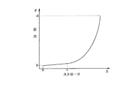
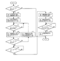
- FIG. 2 is a block diagram for controlling brake operation in the brake system of the example shown in FIG. 1. It is a characteristic line figure of reaction force to the stroke of a brake pedal. It is a figure which shows the flow for performing reaction force control by a stroke simulator. It is a figure which shows typically the master cylinder which has the conventional pedal feeling simulator part described in patent document 1.
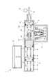
- FIG. 1 It is a figure showing typically a master cylinder which has an example of an embodiment of a stroke simulator concerning the present invention, and a brake system using this master cylinder.
- FIG. 2 is a block diagram for controlling brake operation in the brake system of the example shown in FIG. 1. It is a characteristic line figure of reaction force to the stroke of a brake pedal. It is a figure which shows the flow for performing reaction force control by a stroke simulator. It is a figure which shows typically the master cylinder which has the conventional pedal feeling simulator part described in patent document 1.
- FIG. 1 is a diagram schematically showing a master cylinder having an example of an embodiment of a stroke simulator according to the present invention, and a brake system using the master cylinder.
- symbol is attached
- the master cylinder 1 is used for the brake system 22 of this example.
- the primary hydraulic chamber 9 communicates with one system of brake cylinders 23 and 24, and the secondary hydraulic chamber 10 communicates with the other system of brake cylinders 25 and 26. Communicate.
- the hydraulic pressure operation control device 28 performs a stroke simulation function. Therefore, in the master cylinder 1 of this example, the pedal feel simulator cartridge 17 described in Patent Document 1 for performing the stroke simulation function is not provided.
- a normally closed second electromagnetic flow control valve 41 disposed in a passage 40 that communicates only with the simulator operating hydraulic pressure chamber 15 of the pedal sensation simulator unit 3, and a first pressure that detects the hydraulic pressure of the accumulator 33. It has a pressure sensor 42, a second pressure sensor 43 that detects the hydraulic pressure in the power chamber 13, and a third pressure sensor 44 that detects the hydraulic pressure in the simulator working hydraulic pressure chamber 15.
- the first electromagnetic flow rate control valve 39 can control the flow rate of the hydraulic fluid by controlling the valve opening amount, and the simulator of the pedal feeling simulator unit 3 from the discharge side of the hydraulic pumps 29, 30, 31. This is a one-way valve that allows only the flow of hydraulic fluid toward the hydraulic fluid pressure chamber 15.
- the second electromagnetic flow rate control valve 41 can also control the flow rate of the hydraulic fluid by controlling the valve opening amount, and the hydraulic pump 29 from the simulator hydraulic pressure chamber 15 of the pedal sensation simulator unit 3. , 30, 31 are one-way valves that allow only the flow of hydraulic fluid toward the suction side. Note that the suction sides of the hydraulic pumps 29, 30, 31 communicate with the reservoir tank 6.
- the ECU 45 controls the driving of the pump drive motor 32 based on the hydraulic pressure signal of the accumulator 33 from the first pressure sensor 42 so that the preset hydraulic pressure set in the accumulator 33 is always accumulated. It has become. Further, the ECU 45 controls the operation of the first and second electromagnetic opening / closing valves 35 and 37 based on the stroke signal from the stroke sensor 5, thereby supplying the hydraulic pressure from the accumulator 33 to the power chamber 13 and the reservoir. The hydraulic pressure is discharged to the tank 6.
- the primary piston 7 of the tandem master cylinder section 2 is operated by the hydraulic pressure supplied to the power chamber 13 to generate brake hydraulic pressure in the primary hydraulic pressure chamber 9 and the secondary piston 8 is operated to activate the secondary hydraulic pressure chamber. 10 generates a brake fluid pressure.
- the brake cylinders 23, 24, 25, and 26 By supplying these brake fluid pressures to the brake cylinders 23, 24, 25, and 26, the brake cylinders 23, 24, 25, and 26 generate brake forces, and the brakes are applied to the wheels by these brake forces. It can be applied.
- the ECU 45 sets the brake force so that the brake force becomes a brake force corresponding to the pedal stroke of the brake pedal 27 based on the stroke signal from the stroke sensor 5 and the hydraulic pressure signal of the power chamber 13 from the second pressure sensor 43.
- the first and second electromagnetic opening / closing valves 35 and 37 are controlled to operate.
- the ECU 45 controls the operation of the first and second electromagnetic flow control valves 39 and 41 based on the stroke signal from the stroke sensor 5, so that the hydraulic pressure from the accumulator 33 is controlled with respect to the simulator hydraulic pressure chamber 15. Supply and discharge of the hydraulic pressure to the reservoir tank 6 are performed.
- the reaction force is transmitted to the brake pedal 27 via the simulator operation piston 14 and the input shaft 4 by the hydraulic pressure supplied to the simulator operation hydraulic pressure chamber 15, and the driver recognizes this reaction force.
- the ECU 45 reacts with the reaction force corresponding to the pedal stroke of the brake pedal 27 based on the stroke signal from the stroke sensor 5 and the hydraulic pressure signal of the simulator hydraulic pressure chamber 15 from the third pressure sensor 44.
- the valve opening amounts of the first and second electromagnetic flow control valves 39 and 41 are controlled.
- the relationship between the stroke S of the input shaft 4 and the reaction force F due to the fluid pressure in the simulator working fluid pressure chamber 15 is the characteristic line of the reaction force F with respect to the stroke S of the input shaft 4 shown in FIG. It is set as shown. That is, when the brake pedal 27 is depressed, that is, the stroke of the input shaft 4, the first electromagnetic flow control valve 39 is always closed and the stroke S of the input shaft 4 is changed to the first stroke a (the first shaft 4 of the present invention). The second electromagnetic flow rate control valve 41 is closed until it corresponds to the stroke of Therefore, when the stroke of the input shaft 4 starts (that is, when the brake pedal 27 starts to be depressed), the reaction force F is not substantially generated.
- the second electromagnetic flow control valve 41 is always closed and the first electromagnetic flow control valve 39 is opened.
- the simulator operating piston 14 moves backward, the volume of the simulator operating hydraulic chamber 15 increases, and the hydraulic pressure in the simulator operating hydraulic chamber 15 decreases.
- the hydraulic fluid is supplied from the accumulator 33 to the simulator hydraulic chamber 15 through the first electromagnetic flow control valve 39.
- the ECU 45 controls the hydraulic pressure in the simulator hydraulic pressure chamber 15 by controlling the valve opening amount of the first electromagnetic flow control valve 39 so that the braking force is gradually reduced.
- the relationship with the force F is a characteristic having an appropriate hysteresis with respect to the forward stroke of the input shaft 4 (that is, when the brake pedal 27 is depressed).
- FIG. 4 is a diagram illustrating a flow for performing reaction force control by the stroke simulator.
- step S1 it is determined whether or not the brake pedal 2 is depressed. If it is determined that the brake pedal 2 has not been depressed, the reaction force control ends. If it is determined in step S1 that the brake pedal 2 has been depressed, in step S2, the first electromagnetic switching valve 35 is opened and the second electromagnetic switching valve 37 is closed. In step S3, the second electromagnetic flow control valve 41 is opened while the valve opening amount is controlled (at this time, the first electromagnetic flow control valve 39 is in an initial state and is closed).
- step S4 it is determined whether or not the depression of the brake pedal 2 has been stopped halfway. If it is determined that the depression of the brake pedal 2 is not stopped halfway, the process of step S4 is continued as it is. If it is determined in step S4 that the depression of the brake pedal 2 has been stopped, the first electromagnetic on-off valve 35 is closed and the second electromagnetic flow control valve 41 is closed in step S5. As a result, the brake hydraulic pressure is held at a hydraulic pressure corresponding to the stroke of the brake pedal 2 at that time, and the hydraulic pressure in the simulator hydraulic pressure chamber 15 is held at the hydraulic pressure at that time.
- the hydraulic operation control device 28 has a stroke simulation function.
- the pedal feeling simulator cartridge 17 shown in FIG. 5 described in Patent Document 1 for performing the stroke simulation function becomes unnecessary.
- the some spring provided in the pedal feeling simulator cartridge 17 of patent document 1 is not provided, the standing load of the pedal feeling simulator part 3 can be made small. Therefore, the operation of the stroke simulation function can be started smoothly.
- the load on the brake pedal 27 can be reduced, and the feeling of resistance due to the spring force of a plurality of springs can be reduced.
- a good pedal feeling similar to that of a general brake system in which the reaction force of the brake force is transmitted to the brake pedal.
- the hydraulic fluid moves while the flow rate is controlled by the first and second electromagnetic flow control valves 39 and 41, a response delay due to the volume movement of the hydraulic fluid occurs.
- This response delay is a response of the conventional negative pressure brake system. Since it becomes an alternative to the delay, it is possible to realize a pedal feeling like a conventional negative pressure brake system.
- the opening amount of the first and second electromagnetic flow control valves 39 and 41 is controlled according to the pedal stroke of the brake pedal 27, thereby controlling the volume change amount and the volume change speed of the simulator hydraulic pressure chamber 15. can do. Therefore, the hydraulic pressure, that is, the reaction force of the hydraulic fluid in the simulator hydraulic chamber 15 can be easily controlled according to the pedal stroke. Moreover, the reaction force characteristics with respect to the stroke of the brake pedal 27 can be easily adjusted to the desired characteristics by setting the valve opening amounts of the first and second electromagnetic flow control valves 39 and 41 to the desired magnitude. It becomes possible.
- a stroke simulator, a master cylinder, and a brake system according to the present invention use a stroke simulator that generates a reaction force simulated based on a stroke of an input shaft, a master cylinder having the stroke simulator, and the master cylinder, respectively. It can be suitably used for a brake system.
Landscapes
- Engineering & Computer Science (AREA)
- Transportation (AREA)
- Mechanical Engineering (AREA)
- Physics & Mathematics (AREA)
- Fluid Mechanics (AREA)
- Regulating Braking Force (AREA)
- Braking Systems And Boosters (AREA)
- Transmission Of Braking Force In Braking Systems (AREA)
Abstract
L'invention a pour but d'obtenir une bonne sensation à la pédale dans l'opération de démarrage d'une fonction de simulation de course plus progressive et de former un simulateur de course compact. A cet effet, selon l'invention, une unité simulateur de sensation à la pédale (3) qui sert de simulateur de course comprend : une tige d'entrée (4) qui subit un mouvement de course lors de l'addition d'une entrée ; un piston de commande du simulateur (14) qui subit un mouvement de course dû à la course de l'arbre d'entrée (4) ; une chambre de pression de liquide de commande de simulateur (15) dans laquelle, sous l'effet de la course du piston de commande du simulateur (14), une pression de liquide de commande du simulateur est engendrée de telle sorte qu'une force de réaction basée sur la course de la tige d'entrée (4) est ajoutée au piston de commande du simulateur (14) ; et un dispositif de commande de fonctionnement de la pression de liquide (28) qui commande la pression de liquide de manœuvre du simulateur sur la base de la course de la tige d'entrée (4) en commandant l'amenée du liquide de fonctionnement à la chambre de pression de liquide de commande du simulateur (15) et sa décharge hors de cette chambre.
Priority Applications (2)
| Application Number | Priority Date | Filing Date | Title |
|---|---|---|---|
| CN201280024833.0A CN103547494B (zh) | 2011-05-23 | 2012-05-14 | 行程仿真器、具有该行程仿真器的主缸、以及使用该主缸的制动系统 |
| EP12788898.0A EP2716513B1 (fr) | 2011-05-23 | 2012-05-14 | Simulateur de course, maître-cylindre équipé d'un simulateur de course et système de frein utilisant un maître-cylindre |
Applications Claiming Priority (2)
| Application Number | Priority Date | Filing Date | Title |
|---|---|---|---|
| JP2011-114594 | 2011-05-23 | ||
| JP2011114594A JP2012240601A (ja) | 2011-05-23 | 2011-05-23 | ストロークシミュレータ、このストロークシミュレータを有するマスタシリンダ、およびこのマスタシリンダを用いたブレーキシステム |
Publications (1)
| Publication Number | Publication Date |
|---|---|
| WO2012161016A1 true WO2012161016A1 (fr) | 2012-11-29 |
Family
ID=47217096
Family Applications (1)
| Application Number | Title | Priority Date | Filing Date |
|---|---|---|---|
| PCT/JP2012/062303 Ceased WO2012161016A1 (fr) | 2011-05-23 | 2012-05-14 | Simulateur de course, maître-cylindre équipé d'un simulateur de course et système de frein utilisant un maître-cylindre |
Country Status (4)
| Country | Link |
|---|---|
| EP (1) | EP2716513B1 (fr) |
| JP (1) | JP2012240601A (fr) |
| CN (1) | CN103547494B (fr) |
| WO (1) | WO2012161016A1 (fr) |
Families Citing this family (3)
| Publication number | Priority date | Publication date | Assignee | Title |
|---|---|---|---|---|
| CN104118415B (zh) * | 2014-08-05 | 2015-04-08 | 吉林大学 | 挂车气压制动迟滞补偿装置 |
| US20180093648A1 (en) * | 2016-09-30 | 2018-04-05 | GM Global Technology Operations LLC | Brake pedal emulator of a brake-by-wire system |
| CN107139911A (zh) * | 2017-04-24 | 2017-09-08 | 浙江零跑科技有限公司 | 一种智能化制动主缸 |
Citations (8)
| Publication number | Priority date | Publication date | Assignee | Title |
|---|---|---|---|---|
| JPH04283157A (ja) * | 1991-03-07 | 1992-10-08 | Nissin Kogyo Kk | 流体圧倍力装置 |
| JPH11334577A (ja) * | 1998-05-29 | 1999-12-07 | Tokico Ltd | アキュムレータ |
| JP2000280877A (ja) * | 1999-03-31 | 2000-10-10 | Tokico Ltd | ストロークシミュレータ装置 |
| JP2001301591A (ja) * | 2000-04-05 | 2001-10-31 | Bayerische Motoren Werke Ag | 「ブレーキバイワイヤ」式の自動車両用制動装置のための操作装置 |
| JP2004528214A (ja) * | 2000-09-27 | 2004-09-16 | コンティネンタル・テーベス・アクチエンゲゼルシヤフト・ウント・コンパニー・オッフェネ・ハンデルスゲゼルシヤフト | 車両操作装置用の操作ストロークシミュレータ |
| JP2005112034A (ja) * | 2003-10-03 | 2005-04-28 | Nissan Motor Co Ltd | ブレーキ装置の反力特性制御装置 |
| JP2006248473A (ja) * | 2005-03-14 | 2006-09-21 | Toyota Motor Corp | ブレーキ操作装置および車両用ブレーキ装置 |
| JP4510388B2 (ja) | 2002-02-25 | 2010-07-21 | ロバート ボッシュ ゲゼルシャフト ミット ベシュレンクテル ハフツング | 改良されたペダル感覚シミュレーション手段を備える電気油圧制動システム用のマスターシリンダと、このようなマスターシリンダを備えた電気油圧制動システム |
Family Cites Families (6)
| Publication number | Priority date | Publication date | Assignee | Title |
|---|---|---|---|---|
| JP4075102B2 (ja) * | 1997-07-17 | 2008-04-16 | アイシン精機株式会社 | 車両ブレーキ制御装置 |
| DE60037967T2 (de) * | 2000-07-01 | 2009-03-26 | Robert Bosch Gmbh | Verfahren und Gerät zur Berechnung der Ansteuerung einer hydraulischen FDR/ESP Unterbaugruppe zur Reduzierung hydraulischer Geräusche |
| EP1418105B1 (fr) * | 2002-11-05 | 2006-03-22 | Ford Global Technologies, LLC | Dispositif et procédé de simulation de la caractéristique d'une pédale |
| US20060186733A1 (en) * | 2003-07-11 | 2006-08-24 | Continal Teves Ag & Co. Ohg | Electrohydraulic brake system for motor vehicles |
| FR2874881B1 (fr) * | 2004-09-08 | 2006-12-15 | Bosch Gmbh Robert | Dispositif de freinage pour vehicule automobile |
| CN100577484C (zh) * | 2004-10-15 | 2010-01-06 | 大陆-特韦斯贸易合伙股份公司及两合公司 | 用于机动车辆的制动设备 |
-
2011
- 2011-05-23 JP JP2011114594A patent/JP2012240601A/ja not_active Withdrawn
-
2012
- 2012-05-14 EP EP12788898.0A patent/EP2716513B1/fr active Active
- 2012-05-14 WO PCT/JP2012/062303 patent/WO2012161016A1/fr not_active Ceased
- 2012-05-14 CN CN201280024833.0A patent/CN103547494B/zh not_active Expired - Fee Related
Patent Citations (8)
| Publication number | Priority date | Publication date | Assignee | Title |
|---|---|---|---|---|
| JPH04283157A (ja) * | 1991-03-07 | 1992-10-08 | Nissin Kogyo Kk | 流体圧倍力装置 |
| JPH11334577A (ja) * | 1998-05-29 | 1999-12-07 | Tokico Ltd | アキュムレータ |
| JP2000280877A (ja) * | 1999-03-31 | 2000-10-10 | Tokico Ltd | ストロークシミュレータ装置 |
| JP2001301591A (ja) * | 2000-04-05 | 2001-10-31 | Bayerische Motoren Werke Ag | 「ブレーキバイワイヤ」式の自動車両用制動装置のための操作装置 |
| JP2004528214A (ja) * | 2000-09-27 | 2004-09-16 | コンティネンタル・テーベス・アクチエンゲゼルシヤフト・ウント・コンパニー・オッフェネ・ハンデルスゲゼルシヤフト | 車両操作装置用の操作ストロークシミュレータ |
| JP4510388B2 (ja) | 2002-02-25 | 2010-07-21 | ロバート ボッシュ ゲゼルシャフト ミット ベシュレンクテル ハフツング | 改良されたペダル感覚シミュレーション手段を備える電気油圧制動システム用のマスターシリンダと、このようなマスターシリンダを備えた電気油圧制動システム |
| JP2005112034A (ja) * | 2003-10-03 | 2005-04-28 | Nissan Motor Co Ltd | ブレーキ装置の反力特性制御装置 |
| JP2006248473A (ja) * | 2005-03-14 | 2006-09-21 | Toyota Motor Corp | ブレーキ操作装置および車両用ブレーキ装置 |
Also Published As
| Publication number | Publication date |
|---|---|
| EP2716513A4 (fr) | 2016-03-30 |
| EP2716513A1 (fr) | 2014-04-09 |
| CN103547494A (zh) | 2014-01-29 |
| CN103547494B (zh) | 2016-06-22 |
| EP2716513B1 (fr) | 2018-04-25 |
| JP2012240601A (ja) | 2012-12-10 |
Similar Documents
| Publication | Publication Date | Title |
|---|---|---|
| CN102933440B (zh) | 用于控制机动车的制动系统的方法和控制电路 | |
| JP6063824B2 (ja) | ブレーキ制御装置 | |
| US9254827B2 (en) | Operation of a brake booster as a pedal simulator | |
| EP2048569B1 (fr) | Appareil de freinage | |
| CN105492270B (zh) | 制动控制装置以及制动控制方法 | |
| KR101878110B1 (ko) | 브레이크 장치 | |
| CN104512397B (zh) | 车辆制动系统 | |
| CN103003115A (zh) | 用于机动车的制动系统以及用于运行用于机动车的制动系统的方法 | |
| US20100219679A1 (en) | Brake apparatus | |
| CN106864442A (zh) | 电子液压制动系统 | |
| JP4407396B2 (ja) | 電磁弁制御装置および車両用制動装置 | |
| US20060186733A1 (en) | Electrohydraulic brake system for motor vehicles | |
| WO2012157609A1 (fr) | Simulateur de course, maître cylindre le comportant et système de freinage utilisant le maître cylindre | |
| WO2018096978A1 (fr) | Dispositif de freinage et procédé de commande de dispositif de freinage | |
| CN107074223A (zh) | 车辆的制动装置 | |
| JP2007533542A (ja) | 自動車ブレーキシステムのブレーキ作動ユニットを操作する方法 | |
| WO2012161016A1 (fr) | Simulateur de course, maître-cylindre équipé d'un simulateur de course et système de frein utilisant un maître-cylindre | |
| JP5566873B2 (ja) | 車両用ブレーキ装置 | |
| JP2003025985A (ja) | 車両用ブレーキ液圧発生装置、及び該液圧発生装置を備えた液圧ブレーキ装置 | |
| KR20190096146A (ko) | 전자식 브레이크 시스템 | |
| JP2009513411A (ja) | 自動車用電気油圧式ブレーキシステム | |
| JP2012035737A (ja) | 電動制動装置 | |
| JP5565008B2 (ja) | 制動制御装置 | |
| JP2013049369A (ja) | ストロークシミュレータ、このストロークシミュレータを有するマスタシリンダ、およびこのマスタシリンダを用いたブレーキシステム | |
| JP2012035735A (ja) | 電動制動装置 |
Legal Events
| Date | Code | Title | Description |
|---|---|---|---|
| 121 | Ep: the epo has been informed by wipo that ep was designated in this application |
Ref document number: 12788898 Country of ref document: EP Kind code of ref document: A1 |
|
| WWE | Wipo information: entry into national phase |
Ref document number: 2012788898 Country of ref document: EP |
|
| NENP | Non-entry into the national phase |
Ref country code: DE |