WO2012161069A1 - 基板シートの製造方法 - Google Patents
基板シートの製造方法 Download PDFInfo
- Publication number
- WO2012161069A1 WO2012161069A1 PCT/JP2012/062606 JP2012062606W WO2012161069A1 WO 2012161069 A1 WO2012161069 A1 WO 2012161069A1 JP 2012062606 W JP2012062606 W JP 2012062606W WO 2012161069 A1 WO2012161069 A1 WO 2012161069A1
- Authority
- WO
- WIPO (PCT)
- Prior art keywords
- sheet member
- sheet
- substrate
- small piece
- direction along
- Prior art date
- Legal status (The legal status is an assumption and is not a legal conclusion. Google has not performed a legal analysis and makes no representation as to the accuracy of the status listed.)
- Ceased
Links
Images


Classifications
-
- G—PHYSICS
- G01—MEASURING; TESTING
- G01N—INVESTIGATING OR ANALYSING MATERIALS BY DETERMINING THEIR CHEMICAL OR PHYSICAL PROPERTIES
- G01N1/00—Sampling; Preparing specimens for investigation
- G01N1/28—Preparing specimens for investigation including physical details of (bio-)chemical methods covered elsewhere, e.g. G01N33/50, C12Q
- G01N1/2813—Producing thin layers of samples on a substrate, e.g. smearing, spinning-on
-
- G—PHYSICS
- G01—MEASURING; TESTING
- G01N—INVESTIGATING OR ANALYSING MATERIALS BY DETERMINING THEIR CHEMICAL OR PHYSICAL PROPERTIES
- G01N1/00—Sampling; Preparing specimens for investigation
- G01N1/28—Preparing specimens for investigation including physical details of (bio-)chemical methods covered elsewhere, e.g. G01N33/50, C12Q
- G01N1/286—Preparing specimens for investigation including physical details of (bio-)chemical methods covered elsewhere, e.g. G01N33/50, C12Q involving mechanical work, e.g. chopping, disintegrating, compacting, homogenising
- G01N2001/2873—Cutting or cleaving
Definitions
- the present invention relates to a method for producing a substrate sheet, and more particularly to a substrate sheet for separating minute fragments from a thin section of a living tissue.
- Patent Document 1 since the method of Patent Document 1 requires large-scale equipment and skilled techniques, it is not suitable for general use.
- a technique similar to Patent Document 1 an original substrate such as a cover glass is pasted in an adhesive sheet that can be extended in a state of being divided into small pieces without any gaps, and a tissue section is stuck on the small pieces.
- a method is used in which a tissue section is divided into fragments along the outline of each small piece by extending the sheet and separating the small pieces from each other.
- the small piece group is arranged without gaps on the pressure-sensitive adhesive sheet by manually dividing it using glass cutting with the original substrate attached to the pressure-sensitive adhesive sheet.
- This invention is made in view of the situation mentioned above, Comprising: It provides the manufacturing method of the board
- the present invention provides the following means.
- a cutting step of cutting the original substrate having the one end face bonded to the first sheet member into small pieces, and the other end face of the small pieces after the cutting step A second sheet member that can be contracted in a direction along the surface is adhered, and the first sheet member is peeled off from the one end face of the small piece group, whereby the small piece group is attached to the second sheet member.
- a substrate sheet manufacturing method comprising: a transfer step of transferring; and a contraction step of contracting the second sheet member in a direction along the surface after the transfer step.
- the original substrate is cut into small pieces on the first sheet member in the cutting step, and transferred to the second sheet member with these small pieces arranged in the transfer step. Thereafter, by shrinking the second sheet member in the shrinking step, the gaps between the small pieces generated at the time of cutting can be closed, and the small piece groups can be arranged without gaps.
- the second sheet member is extendable in a direction along the surface, and the transfer step transfers the small piece group in a state where the second sheet member is extended.
- the contraction step may contract the second sheet member by releasing a tensile force in a direction along the surface of the second sheet member.
- the second sheet member may have heat shrinkability, and the shrinking step may shrink the second sheet member by heating. By doing in this way, the 2nd sheet member can be shrunk simply.
- a cutting step of cutting the original substrate having the one end face bonded to the first sheet member capable of contracting in the direction along the surface thereof into small pieces and after the cutting step, A shrinking step of shrinking the first sheet member in a direction along the surface; and after the shrinking step, a second sheet member is bonded to the other end surface of the small piece group, and the first sheet member is And a transfer step of transferring the small piece group to the second sheet member by peeling from the one end face of the small piece group.
- the first sheet member is extendable in a direction along the surface, and the cutting step cuts the small piece group in a state where the first sheet member is extended.
- the shrinking step may shrink the first sheet member by releasing a tensile force in a direction along the surface of the first sheet.
- the first sheet member may have heat shrinkability, and the shrinking step may shrink the first sheet member by heating.
- the original substrate is bonded to the first sheet member with an ultraviolet peelable adhesive whose adhesive strength is reduced by irradiation of ultraviolet rays, and the transfer step includes the first step.
- the first sheet member may be peeled off from the one end face of the small piece group by irradiating the sheet member with ultraviolet rays.
- the original substrate is bonded to the first sheet member with a temperature-sensitive adhesive whose adhesive force is reduced by a temperature change, and the transfer step includes the first step.
- the first sheet member may be peeled off from the one end face of the small piece group by heating or cooling the sheet member. By doing in this way, a 1st sheet
- the transfer step may adhere the second sheet member to the other end surface of the small piece group with a stronger adhesive force than the first sheet member. .
- a 1st sheet member can be easily peeled from a small piece group, making the small piece group adhere to the 2nd sheet member which has adhered with greater power.
- the transfer step transfers small pieces in different regions of the small piece group to the plurality of second sheet members. May be.
- seat is manufactured by one cutting step, and manufacturing efficiency can be improved.
- by changing the arrangement and number of small pieces transferred to the second sheet member it is possible to easily manufacture a substrate sheet in which small pieces are arranged in an arbitrary shape.
- the first sheet member is extendable in a direction along the surface, and the cutting step cuts the small piece group in a state where the first sheet member is extended.
- the contraction step may contract the first sheet member by releasing a tensile force in a direction along the surface of the first sheet member.
- the first sheet member may have heat shrinkability, and the shrinking step may shrink the first sheet member by heating.
- the group of small pieces of the divided original substrate can be arranged on the sheet without a gap by a simple method.
- FIG. 1 It is a flowchart which shows the manufacturing method of the board
- the substrate sheet manufacturing method includes a flat base substrate 1 on which one tissue section can be attached to one end face, and a shrinkable sheet (first sheet member).
- the cutting step S1 is a group of small pieces 1a in the shape of ridges having substantially the same dimensions in a state where one end face is adhered to the surface of the shrinkable sheet 2 as shown in FIG. This is done by cutting into pieces.
- a cutting apparatus such as a dicer used for cutting a wafer in a semiconductor manufacturing process is used for cutting the original substrate 1.
- the small pieces 1a remain in an aligned state on the shrinkable sheet 2, and a gap having a width corresponding to the thickness of the blade of the cutting device is left between the small pieces 1a. A is formed.
- the size of one side of the small piece 1a is preferably a size suitable for an operation such as gene analysis, for example, about 0.1 mm to 5 mm that can be accommodated in each well of the microplate.
- the thickness of the original substrate 1 may be any thickness that can be easily cut by a cutting device and can be easily handled, and is preferably about 0.05 mm to 0.5 mm.
- the original substrate 1 a material that can be cut relatively easily by a cutting device, for example, a glass, silicon, metal, or resin is used.
- the surface of at least one end face of the original substrate 1 may be subjected to a surface treatment such as silanization in order to improve the adhesion with the tissue section.
- the shrinkable sheet 2 is made of a thermoplastic resin such as polyvinyl chloride or polyester and has heat shrinkability, and the adhesive B is applied to the surface.
- Adhesive B is an ultraviolet peelable adhesive that loses its adhesive strength when irradiated with ultraviolet rays.
- the small pieces 1a may be cleaned with ultrasonic waves or the like while being adhered on the shrinkable sheet 2.
- the shrinking step S2 is performed by heating the shrinkable sheet 2. Thereby, as shown in (c) in FIG. 2, the shrinkable sheet 2 shrinks in the direction along the surface thereof, and the adjacent small pieces 1 a come into close contact with each other, and the gap A is closed.
- the transfer step S3 is performed using the extensible sheet 3 that is coated with the ultraviolet peelable adhesive B on the surface in the same manner as the shrinkable sheet 2 and can be extended in the direction along the surface. That is, after the shrinkable sheet 2 is irradiated with ultraviolet light to sufficiently reduce the adhesive force of the adhesive B, the surface of the extensible sheet 3 is made of small pieces 1a as shown in FIG. Then, the shrinkable sheet 2 is peeled off from one end face of the small piece 1a group, as shown in (e) of FIG. As a result, the group of small pieces 1a on the shrinkable sheet 2 is moved onto the extensible sheet 3 while being aligned, and the substrate sheet 10 in which the small pieces 1a are aligned on the extensible sheet 3 without gaps A is manufactured. Can do.
- channel conventionally performed manually by the operator using glass cutting is unnecessary, and is easy.
- the small pieces 1a can be arranged on the sheets 2 and 3 without a gap A by only a simple operation.
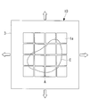
- the substrate sheet 10 thus manufactured is used as follows. First, as shown in FIG. 3A, a tissue section C is pasted on the small piece 1a group of the substrate sheet 10, and the extensible sheet 3 is extended in a direction along the surface thereof. Thereby, as FIG. 3B shows, the small pieces 1a are mutually pulled apart and the clearance gap A opens. At this time, the tissue slice C is also pulled in the direction along the surface, so that it is divided along the lattice-shaped gap A into pieces having substantially the same shape as one end face of the small piece 1a. The user can collect the fragments of the tissue section C together with the small pieces 1a by peeling the small pieces 1a from the extensible sheet 3.
- the UV-peelable adhesive is used as the adhesive B, but instead of this, a temperature-sensitive adhesive that loses its adhesive force by heating or cooling may be used. Good.
- the shrinkable sheet 2 is heated or cooled instead of the ultraviolet irradiation. Even if it does in this way, the contractible sheet 2 can be easily peeled from the small pieces 1a group without disturbing the alignment of the small pieces 1a group.
- an adhesive having a sufficiently stronger adhesive force than the adhesive applied to the shrinkable sheet 2 may be used as the adhesive applied to the extensible sheet 3. Even in this case, the shrinkable sheet 2 can be easily peeled from the small piece 1a group while leaving the small piece 1a group on the surface of the extensible sheet 3 bonded with a stronger adhesive force without being displaced. Can do.
- the shrinkable sheet 2 and the extensible sheet 3 it is possible to use a combination of dicing adhesive tapes and masking tapes that protect the surface of the material, which have different adhesive strengths.
- SV-224 adheresive strength: 1.1 N / 20 mm
- UE-111AJ adheresive strength: 8.3 N / 20 mm
- Nitto Denko can be used as the shrinkable sheet 2 and the extensible sheet 3, respectively.
- UE-1088JM asdhesive strength: 6.0 N / 20 mm
- UE-111AJ manufactured by Nitto Denko can also be used as the shrinkable sheet 2 and the extensible sheet 3, respectively.
- the original substrate 1 is a substrate that can be pasted with a single tissue section.
- a substrate having a size that can be pasted with a plurality of tissue sections may be used. Good.
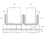
- the transfer step S3 is performed by covering the end surface of the columnar pressing member 4 with the extensible sheet 3 and pressing the end surface of the pressing member 4 against the small piece 1a group. Is called. Thereby, small pieces of different regions in the small piece 1 a group are transferred to the plurality of extensible sheets 3.
- the extensibility sheet 3 may be protected by a protective sheet 5 that does not adhere to each other, except for the area where the small pieces 1a are adhered.
- the protective sheet a thin resin sheet such as a polypropylene sheet is preferable.
- the substrate sheet 10 in which the small pieces 1a group are arranged in an arbitrary size and shape can be easily manufactured.
- the cutting step S1 for manufacturing the plurality of substrate sheets 10 may be performed once, and the manufacturing efficiency can be improved.
- the shrinkable sheet 2 a sheet that can be reversibly stretched in the direction along the surface thereof is used, and the substrate sheet 10 in which the small pieces 1a are arranged on the shrinkable sheet 2 is manufactured. May be.
- the shrinkable sheet 2 for example, a sheet made of an elastic material such as rubber is used.
- the original substrate 1 is cut in a state where the shrinkable sheet 2 is pulled and extended in the direction along the surface.
- the shrinkable sheet 2 is shrunk by the self-shrinking force by releasing from the external force that has been pulled. And when dividing
- the transfer step S3 is performed after the contraction step S2, but instead, as shown in FIG. 5, the contraction step S21 is performed after the transfer steps S31 to S33. Good.
- the sheet member (first sheet member) used in the cutting step S11 is not particularly limited as long as the original substrate 1 can be bonded.
- the transfer sheet member (second sheet member) used in the transfer steps S31 to S33 has a property of contracting to the original shape without being plastically deformed with respect to extension within a certain range.
- An adhesive sheet member is used.
- step S33 by transferring the small piece group in a state where the elastic sheet member is extended (step S32) (step S33), only the tensile force applied to the elastic sheet member in the contraction step S21 is released.
- the elastic sheet member can be contracted to close the gap between the small pieces.
- a means for extending the stretchable sheet member for example, a wafer expander used when expanding the interval between chips after dicing a semiconductor wafer into chips can be suitably used.
- the transfer sheet member may be any material that can contract, such as the contractible sheet 2 described above.
- resins such as polyvinyl chloride, polyolefin, polyethylene terephthalate, etc. used for semiconductor dicing tape are suitable.
- an adhesive applied to the stretchable sheet member an ultraviolet peelable adhesive generally used for a semiconductor dicing tape is preferably used.
- an adhesive applied to the stretchable sheet member is stronger than the adhesive applied to the sheet member used in the cutting step S11, the small piece 1a group can be transferred. Can be made easier.
- the small sheet group is transferred to a stretchable sheet member (second sheet member) previously stretched as shown in FIG. 5, and the stretchable sheet member is contracted by releasing from the stretched state after the transfer.
- a method for closing the interval between the small pieces will be described.
- an 18 mm square cover glass made of matsunami glass
- a dicing tape (UE-111AJ, made by Nitto Denko) as the first sheet member.
- UE-111AJ made by Nitto Denko
- the adhesive force of the adhesive applied to the first sheet member was reduced by irradiating the first sheet member with ultraviolet rays.
- the ultraviolet light source an ultraviolet light emitting diode light source composed of ZUV-C10 (control device, manufactured by OMRON) and ZUV-H10 (LED head, manufactured by OMRON) was used.
- the output of ultraviolet rays at this time was 150 mW at a wavelength of 365 nm.
- the ultraviolet irradiation was performed for 60 seconds at 100% output while moving the head on the back side of the first sheet member so that all the small pieces were uniformly irradiated with the ultraviolet rays.
- seat made from polyethylene was affixed on the part where the small piece group of the surface of the 1st sheet member is not affixed, and it protected so that it could not expose except the part which affixed the small piece group.
- the dicing tape (UE-111AJ) as the second sheet member was extended using a wafer expander and held in the extended state. At this time, the second sheet member extended about 6% in the surface direction.
- the second sheet member is covered with the first sheet member whose adhesive strength has been lowered so that the small piece group is sandwiched between the second sheet member and the rubber. The small piece group was sufficiently adhered to the second sheet member by rolling the roller behind the first sheet member. Next, the small sheet group was transferred to the second sheet member by slowly peeling off the first sheet member.
- the second sheet member to which the small piece group was transferred was removed from the wafer expander and released from the extended state, whereby the second sheet member was contracted. And when the whole magnitude
Landscapes
- Immunology (AREA)
- Pathology (AREA)
- Life Sciences & Earth Sciences (AREA)
- Chemical & Material Sciences (AREA)
- Analytical Chemistry (AREA)
- Biochemistry (AREA)
- Health & Medical Sciences (AREA)
- General Health & Medical Sciences (AREA)
- Physics & Mathematics (AREA)
- General Physics & Mathematics (AREA)
- Laminated Bodies (AREA)
- Sampling And Sample Adjustment (AREA)
- Dicing (AREA)
- Re-Forming, After-Treatment, Cutting And Transporting Of Glass Products (AREA)
- Container, Conveyance, Adherence, Positioning, Of Wafer (AREA)
- Shaping By String And By Release Of Stress In Plastics And The Like (AREA)
Abstract
Description
本発明の第1の態様は、第1のシート部材に前記一方の端面が接着された元基板を小片群に切断する切断ステップと、該切断ステップの後に、前記小片群の他方の端面に、その表面に沿う方向に収縮可能な第2のシート部材を接着し、前記第1のシート部材を前記小片群の前記一方の端面から剥離することにより、前記小片群を前記第2のシート部材に転写する転写ステップと、該転写ステップの後に、前記第2のシート部材を前記表面に沿う方向に収縮させる収縮ステップとを備える基板シートの製造方法である。
このようにすることで、第2のシート部材を簡便に収縮させることができる。
上記第2の態様においては、前記第1のシート部材が、熱収縮性を有し、前記収縮ステップが、加熱によって前記第1のシート部材を収縮させることとしてもよい。
このようにすることで、第1のシート部材を小片群から容易に剥離することができる。
このようにすることで、より大きな力で接着している第2のシート部材に小片群を接着させたまま第1のシート部材を小片群から容易に剥離することができる。
このようにすることで、一度の切断ステップで複数の基板シートが製造され、製造効率を向上することができる。また、第2のシート部材に転写する小片の配列や数を変更することにより、容易に任意の形状に小片群が配列された基板シートを製造することができる。
上記第3の態様においては、前記第1のシート部材が、熱収縮性を有し、前記収縮ステップが、加熱によって前記第1のシート部材を収縮させてもよい。
本実施形態に係る基板シートの製造方法は、図1に示されるように、一方の端面に1枚の組織切片を貼り付け可能な平板状の元基板1を収縮性シート(第1のシート部材)2上において切断する切断ステップS1と、収縮性シート2を収縮させる収縮ステップS2と、切断された元基板1を収縮性シート2から伸展性シート(第2のシート部材)3に転写する転写ステップS3とを備えている。
収縮ステップS2は、収縮性シート2を加熱することにより行われる。これにより、図2中の(c)に示されるように、収縮性シート2がその表面に沿う方向に収縮して隣接する小片1a同士が密着し、隙間Aが閉じられる。
まず、図3Aに示されるように、基板シート10の小片1a群上に組織切片Cを貼り付け、伸展性シート3をその表面に沿う方向に伸展させる。これにより、図3Bに示されるように、小片1a同士が互いに引き離されて隙間Aが開く。このときに、組織切片Cも表面に沿う方向に引っ張られることにより、格子状の隙間Aに沿って小片1aの一方の端面と略同一の形状の断片に分割される。使用者は、伸展性シート3から小片1aを剥離することにより、該小片1aとともに組織切片Cの断片を回収することができる。
このようにしても、小片1a群の整列を乱すことなく収縮性シート2を小片1a群から容易に剥離することができる。
例えば、日東電工製のSV-224(接着力:1.1N/20mm)とUE-111AJ(接着力:8.3N/20mm)とをそれぞれ収縮性シート2および伸展性シート3として使用することができる。また、日東電工製のUE-1088JM(接着力:6.0N/20mm)とUE-111AJとをそれぞれ収縮性シート2および伸展性シート3として使用することもできる。
このようにすることで、転写ステップS3を省いてさらに簡便に基板シート10を製造することができる。
この場合には、切断ステップS11において使用されるシート部材(第1のシート部材)は、元基板1を接着可能であれば特に制限はない。
本実施例では、図5に示される、予め伸展させた伸縮性シート部材(第2のシート部材)に小片群を転写し、転写後に伸展状態から解放することにより伸縮性シート部材を収縮させて小片の間隔を閉塞する方法について示す。
まず、0.13mmから0.17mmの厚さを有する18mm角のカバーガラス(マツナミガラス製)を、水洗した後に、第1のシート部材であるダイシングテープ(UE-111AJ、日東電工製)に貼り付け、ダイシングソーにより約1mmの間隔で小片群に切断した。これにより、カバーガラスは、一辺当たり19個に分割するダイシングがなされた。このときに小片間に形成された切りしろは、約80μmであった。
1a 小片
2 収縮性シート(第1のシート部材)
3 伸展性シート(第2のシート部材)
4 押し当て部材
5 保護シート
10 基板シート
S1,S11 切断ステップ
S2,S21 収縮ステップ
S3,S31,S32,S33 転写ステップ
A 隙間
B 接着剤
Claims (13)
- 第1のシート部材に一方の端面が接着された元基板を小片群に切断する切断ステップと、
該切断ステップの後に、前記小片群の他方の端面に、その表面に沿う方向に収縮可能な第2のシート部材を接着し、前記第1のシート部材を前記小片群の前記一方の端面から剥離することにより、前記小片群を前記第2のシート部材に転写する転写ステップと、
該転写ステップの後に、前記第2のシート部材を前記表面に沿う方向に収縮させる収縮ステップとを備える基板シートの製造方法。 - 前記第2のシート部材が、前記表面に沿う方向に伸展可能であり、
前記転写ステップが、前記第2のシート部材を伸展させた状態で前記小片群を転写し、
前記収縮ステップが、前記第2のシート部材の前記表面に沿う方向の引張力を解除することにより前記第2のシート部材を収縮させる請求項1に記載の基板シートの製造方法。 - 前記第2のシート部材が、熱収縮性を有し、
前記収縮ステップが、加熱によって前記第2のシート部材を収縮させる請求項1に記載の基板シートの製造方法。 - その表面に沿う方向に収縮可能な第1のシート部材に一方の端面が接着された元基板を小片群に切断する切断ステップと、
該切断ステップの後に、前記第1のシート部材を前記表面に沿う方向に収縮させる収縮ステップと、
該収縮ステップの後に、前記小片群の他方の端面に第2のシート部材を接着し、前記第1のシート部材を前記小片群の前記一方の端面から剥離することにより、前記小片群を前記第2のシート部材に転写する転写ステップとを備える基板シートの製造方法。 - 前記第1のシート部材が、前記表面に沿う方向に伸展可能であり、
前記切断ステップが、前記第1のシート部材を伸展させた状態で前記小片群を切断し、
前記収縮ステップが、前記第1のシートの前記表面に沿う方向の引張力を解除することにより前記第1のシート部材を収縮させる請求項4に記載の基板シートの製造方法。 - 前記第1のシート部材が、熱収縮性を有し、
前記収縮ステップが、加熱によって前記第1のシート部材を収縮させる請求項4に記載の基板シートの製造方法。 - 前記元基板が、紫外線の照射によって接着力が低下する紫外線剥離性接着剤により前記第1のシート部材に接着され、
前記転写ステップが、前記第1のシート部材に紫外線を照射することにより該第1のシート部材を前記小片群の前記一方の端面から剥離する請求項1から請求項6のいずれかに記載の基板シートの製造方法。 - 前記元基板が、温度変化によって接着力が低下する感温性接着剤により前記第1のシート部材に接着され、
前記転写ステップが、前記第1のシート部材を加熱または冷却することにより該第1のシート部材を前記小片群の前記一方の端面から剥離する請求項1から請求項6のいずれかに記載の基板シートの製造方法。 - 前記転写ステップが、前記第2のシート部材を、前記第1のシート部材よりも強い接着力で前記小片群の前記他方の端面に接着する請求項1から請求項6のいずれかに記載の基板シートの製造方法。
- 前記第2のシート部材が、複数であって、
前記転写ステップが、前記小片群のうち異なる領域の小片を前記複数の第2のシート部材に転写する請求項1から請求項9のいずれかに記載の基板シートの製造方法。 - その表面に沿う方向に収縮可能な第1のシート部材に一方の端面が接着された元基板を小片群に切断する切断ステップと、
該切断ステップの後に、前記第1のシート部材を前記表面に沿う方向に収縮させる収縮ステップとを備える基板シートの製造方法。 - 前記第1のシート部材が、前記表面に沿う方向に伸展可能であり、
前記切断ステップが、前記第1のシート部材を伸展させた状態で前記小片群を切断し、
前記収縮ステップが、前記第1のシート部材の前記表面に沿う方向の引張力を解除することにより前記第1のシート部材を収縮させる請求項11に記載の基板シートの製造方法。 - 前記第1のシート部材が、熱収縮性を有し、
前記収縮ステップが、加熱によって前記第1のシート部材を収縮させる請求項11に記載の基板シートの製造方法。
Priority Applications (4)
| Application Number | Priority Date | Filing Date | Title |
|---|---|---|---|
| CN201280023190.8A CN103547905B (zh) | 2011-05-20 | 2012-05-17 | 基板片的制造方法 |
| JP2013516322A JP5907959B2 (ja) | 2011-05-20 | 2012-05-17 | 基板シートの製造方法 |
| EP12788956.6A EP2711683B1 (en) | 2011-05-20 | 2012-05-17 | Method of manufacturing base sheet |
| US14/069,521 US9274033B2 (en) | 2011-05-20 | 2013-11-01 | Substrate-sheet fabricating method |
Applications Claiming Priority (2)
| Application Number | Priority Date | Filing Date | Title |
|---|---|---|---|
| JP2011-113361 | 2011-05-20 | ||
| JP2011113361 | 2011-05-20 |
Related Child Applications (1)
| Application Number | Title | Priority Date | Filing Date |
|---|---|---|---|
| US14/069,521 Continuation US9274033B2 (en) | 2011-05-20 | 2013-11-01 | Substrate-sheet fabricating method |
Publications (1)
| Publication Number | Publication Date |
|---|---|
| WO2012161069A1 true WO2012161069A1 (ja) | 2012-11-29 |
Family
ID=47217147
Family Applications (1)
| Application Number | Title | Priority Date | Filing Date |
|---|---|---|---|
| PCT/JP2012/062606 Ceased WO2012161069A1 (ja) | 2011-05-20 | 2012-05-17 | 基板シートの製造方法 |
Country Status (5)
| Country | Link |
|---|---|
| US (1) | US9274033B2 (ja) |
| EP (1) | EP2711683B1 (ja) |
| JP (1) | JP5907959B2 (ja) |
| CN (1) | CN103547905B (ja) |
| WO (1) | WO2012161069A1 (ja) |
Cited By (1)
| Publication number | Priority date | Publication date | Assignee | Title |
|---|---|---|---|---|
| WO2015125343A1 (ja) * | 2014-02-18 | 2015-08-27 | オリンパス株式会社 | 細胞分取方法 |
Families Citing this family (3)
| Publication number | Priority date | Publication date | Assignee | Title |
|---|---|---|---|---|
| JP6351490B2 (ja) * | 2014-11-26 | 2018-07-04 | 株式会社ディスコ | パッケージ基板の分割方法 |
| PL239754B1 (pl) * | 2017-12-12 | 2022-01-03 | Piotrowska Anna Ars Hw Spolka Cywilna | Sposob ustalania polozenia pretow zbrojenia w elementach zelbetowych oraz listwa dystansowa do realizacji sposobu |
| EP3974173A4 (en) * | 2020-02-17 | 2023-07-19 | Yoneshimafelt Co., Ltd. | LAMINATE, METHOD FOR MAKING INTERMEDIATE SHEET AND METHOD FOR MAKING COMPOSITE MATERIAL |
Citations (6)
| Publication number | Priority date | Publication date | Assignee | Title |
|---|---|---|---|---|
| JPH11148887A (ja) * | 1997-11-17 | 1999-06-02 | Japan Science & Technology Corp | 生体サンプルの切断方法および切断片回収方法、 並びにそのための装置 |
| JP2002202229A (ja) * | 2000-10-31 | 2002-07-19 | Fuji Photo Film Co Ltd | 生体試料の切断方法およびそれに用いる装置 |
| JP2002286592A (ja) * | 2001-03-22 | 2002-10-03 | Olympus Optical Co Ltd | サンプルからその一部分を選抜する方法、その選抜方法に用いる担体、その選抜用担体の製造方法およびその選抜を行う装置 |
| JP2003521685A (ja) * | 2000-01-25 | 2003-07-15 | エスエル マイクロテスト ビッセンシャフトリケ ゲレーテ ゲーエムベーハー | 生物学的材料層の一部を単離する方法 |
| JP2005335020A (ja) * | 2004-05-27 | 2005-12-08 | Nano Photonics Kenkyusho:Kk | 微小物体加工装置 |
| JP3786711B2 (ja) | 1997-02-07 | 2006-06-14 | アークテュラス エンジニアリング インコーポレイテッド | レーザー捕捉顕微解剖法と装置 |
Family Cites Families (31)
| Publication number | Priority date | Publication date | Assignee | Title |
|---|---|---|---|---|
| US3448510A (en) * | 1966-05-20 | 1969-06-10 | Western Electric Co | Methods and apparatus for separating articles initially in a compact array,and composite assemblies so formed |
| SE383229B (sv) | 1968-01-10 | 1976-03-01 | Western Electric Co | Sett att hantera halvbrickor och apparat for genomforande av settet. |
| US3932220A (en) | 1970-08-11 | 1976-01-13 | Liotta Lance A | Method for isolating bacterial colonies |
| JPS54121696A (en) * | 1978-03-14 | 1979-09-20 | Sumitomo Electric Ind Ltd | Superconductive electromagnet |
| JPS5946429B2 (ja) | 1978-12-22 | 1984-11-12 | 株式会社東芝 | 発光表示装置の製造方法 |
| ATE33717T1 (de) | 1983-02-25 | 1988-05-15 | Winfried Dr Med Stoecker | Verfahren und vorrichtungen fuer untersuchungen an unbeweglich gemachtem biologischem material. |
| US4752347A (en) | 1986-10-03 | 1988-06-21 | Rada David C | Apparatus for preparing tissue sections |
| JPH01104682A (ja) * | 1987-10-19 | 1989-04-21 | Modern Plast Kogyo Kk | 熱収縮性粘着シート |
| JPH05259277A (ja) * | 1992-03-11 | 1993-10-08 | Nec Kyushu Ltd | 半導体装置の製造方法 |
| ES2152258T3 (es) * | 1992-07-31 | 2001-02-01 | Du Pont | Metodo y producto para montaje de particulas. |
| JP2967806B2 (ja) * | 1994-12-19 | 1999-10-25 | 日東電工株式会社 | 貼着材及びその製造方法 |
| WO1997029354A1 (de) | 1996-02-05 | 1997-08-14 | Bayer Aktiengesellschaft | Verfahren und vorrichtung zum sortieren und zur gewinnung von planar ausgebrachten biologischen objekten wie biologische zellen bzw. zellorganellen, histologischen schnitten, chromosomenteilchen etc. mit laserstrahlen |
| JP3604108B2 (ja) | 1997-02-17 | 2004-12-22 | 株式会社シチズン電子 | チップ型光半導体の製造方法 |
| JP3955659B2 (ja) * | 1997-06-12 | 2007-08-08 | リンテック株式会社 | 電子部品のダイボンディング方法およびそれに使用されるダイボンディング装置 |
| JPH11163006A (ja) | 1997-11-27 | 1999-06-18 | Hitachi Ltd | ペレットボンディング方法 |
| JP2004537712A (ja) | 2000-10-18 | 2004-12-16 | バーチャル・アレイズ・インコーポレーテッド | 多重細胞分析システム |
| CA2424176A1 (en) | 2000-10-18 | 2002-05-16 | Virtual Arrays, Inc. | Multiplexed cell analysis system |
| US6733987B2 (en) | 2000-10-31 | 2004-05-11 | Fuji Photo Film Co., Ltd. | Method for cutting a biological sample and a device used therefor |
| CA2411524C (en) | 2000-12-08 | 2007-02-27 | Flexcell International Corporation | Method and apparatus to grow and mechanically condition cell cultures |
| JP2003007652A (ja) | 2001-06-26 | 2003-01-10 | Mitsubishi Electric Corp | 半導体チップの製造方法 |
| JP2003152056A (ja) | 2001-11-08 | 2003-05-23 | Sony Corp | 半導体素子保持具及びその製造方法 |
| JP2004180521A (ja) * | 2002-11-29 | 2004-07-02 | Yoshio Inoue | 麺線間拡縮装置 |
| JP2005034058A (ja) | 2003-07-15 | 2005-02-10 | Nitto Denko Corp | 微生物または細胞の試験方法及び該方法に使用する粘着シート |
| FR2878859B1 (fr) | 2004-12-02 | 2007-03-23 | Alphelys Sarl | Dispositif de prelevement de carottes pour tissue array |
| US8122804B2 (en) | 2006-11-01 | 2012-02-28 | Kurume University | Slicing guide device for preparing texture slices, texture slices preparing device, and method for preparing texture slices |
| JP2008286528A (ja) | 2007-05-15 | 2008-11-27 | Commercial Resource Ltd | マイクロナイフとマイクロナイフ製造方法 |
| JP2009044123A (ja) | 2007-07-19 | 2009-02-26 | Citizen Finetech Miyota Co Ltd | 電子部品の製造方法および電子部品。 |
| JP5710098B2 (ja) | 2008-03-27 | 2015-04-30 | 日立化成株式会社 | 半導体装置の製造方法 |
| JP5493460B2 (ja) | 2008-08-20 | 2014-05-14 | 日立化成株式会社 | 半導体装置の製造方法及びダイシングテープ一体型接着シート |
| IT1394333B1 (it) * | 2009-04-14 | 2012-06-06 | Del Sarto | Elemento adesivo per prova di adesione e relativo procedimento di prova |
| JP5715125B2 (ja) | 2010-05-28 | 2015-05-07 | オリンパス株式会社 | 細胞分取装置、細胞分取システムおよび細胞分取方法 |
-
2012
- 2012-05-17 WO PCT/JP2012/062606 patent/WO2012161069A1/ja not_active Ceased
- 2012-05-17 EP EP12788956.6A patent/EP2711683B1/en not_active Not-in-force
- 2012-05-17 JP JP2013516322A patent/JP5907959B2/ja active Active
- 2012-05-17 CN CN201280023190.8A patent/CN103547905B/zh active Active
-
2013
- 2013-11-01 US US14/069,521 patent/US9274033B2/en active Active
Patent Citations (6)
| Publication number | Priority date | Publication date | Assignee | Title |
|---|---|---|---|---|
| JP3786711B2 (ja) | 1997-02-07 | 2006-06-14 | アークテュラス エンジニアリング インコーポレイテッド | レーザー捕捉顕微解剖法と装置 |
| JPH11148887A (ja) * | 1997-11-17 | 1999-06-02 | Japan Science & Technology Corp | 生体サンプルの切断方法および切断片回収方法、 並びにそのための装置 |
| JP2003521685A (ja) * | 2000-01-25 | 2003-07-15 | エスエル マイクロテスト ビッセンシャフトリケ ゲレーテ ゲーエムベーハー | 生物学的材料層の一部を単離する方法 |
| JP2002202229A (ja) * | 2000-10-31 | 2002-07-19 | Fuji Photo Film Co Ltd | 生体試料の切断方法およびそれに用いる装置 |
| JP2002286592A (ja) * | 2001-03-22 | 2002-10-03 | Olympus Optical Co Ltd | サンプルからその一部分を選抜する方法、その選抜方法に用いる担体、その選抜用担体の製造方法およびその選抜を行う装置 |
| JP2005335020A (ja) * | 2004-05-27 | 2005-12-08 | Nano Photonics Kenkyusho:Kk | 微小物体加工装置 |
Non-Patent Citations (1)
| Title |
|---|
| See also references of EP2711683A4 * |
Cited By (1)
| Publication number | Priority date | Publication date | Assignee | Title |
|---|---|---|---|---|
| WO2015125343A1 (ja) * | 2014-02-18 | 2015-08-27 | オリンパス株式会社 | 細胞分取方法 |
Also Published As
| Publication number | Publication date |
|---|---|
| CN103547905A (zh) | 2014-01-29 |
| JPWO2012161069A1 (ja) | 2014-07-31 |
| US9274033B2 (en) | 2016-03-01 |
| US20140080174A1 (en) | 2014-03-20 |
| CN103547905B (zh) | 2015-09-09 |
| EP2711683A1 (en) | 2014-03-26 |
| EP2711683A4 (en) | 2014-12-03 |
| EP2711683B1 (en) | 2016-08-03 |
| JP5907959B2 (ja) | 2016-04-26 |
Similar Documents
| Publication | Publication Date | Title |
|---|---|---|
| JP4447280B2 (ja) | 表面保護用シートおよび半導体ウエハの研削方法 | |
| CN110047745B (zh) | 处理晶圆的方法 | |
| CN109417049B (zh) | 处理背面上具有突出物的晶片的方法 | |
| TW201501222A (zh) | 半導體晶片之製造方法 | |
| JP2016171262A (ja) | 半導体ウェハの処理方法、半導体チップおよび表面保護テープ | |
| JP2010073897A (ja) | レーザーダイシングシートおよび半導体チップの製造方法 | |
| JP5907959B2 (ja) | 基板シートの製造方法 | |
| JP4476848B2 (ja) | レーザーダイシングシートおよびレーザーダイシング方法 | |
| WO2016107630A1 (en) | Protective sheeting for use in processing a semiconductor-sized wafer and semiconductor-sized wafer processing method | |
| JP5522773B2 (ja) | 半導体ウエハの保持方法、チップ体の製造方法、およびスペーサ | |
| JP6067348B2 (ja) | ウェーハの加工方法 | |
| JP4757442B2 (ja) | チップ体製造用粘着シート | |
| US11842926B2 (en) | Method of processing a substrate | |
| KR102181999B1 (ko) | 확장 시트, 확장 시트의 제조 방법 및 확장 시트의 확장 방법 | |
| JP2015076422A (ja) | 粘接着剤層付き半導体チップの製造方法 | |
| JP2019096801A (ja) | ウェーハの加工方法 | |
| JP6423569B2 (ja) | 接着シートおよびその使用方法 | |
| JP2016213282A (ja) | 保護テープの剥離方法 | |
| JP5149779B2 (ja) | 半導体ウエハの保持方法、ダイシング方法、およびスペーサ | |
| US20230268185A1 (en) | Manufacturing method of semiconductor device | |
| JP6029481B2 (ja) | レーザーダイシングシートおよび半導体チップの製造方法 | |
| JP2014152287A (ja) | 粘着シートの貼着方法 | |
| CN201436147U (zh) | 晶片研磨及切割保护结构 | |
| JP2010239030A (ja) | 半導体ウエハの加工方法 | |
| KR101930258B1 (ko) | 유리기판 척에 대한 유연 기판의 척킹 및 디척킹 방법 |
Legal Events
| Date | Code | Title | Description |
|---|---|---|---|
| 121 | Ep: the epo has been informed by wipo that ep was designated in this application |
Ref document number: 12788956 Country of ref document: EP Kind code of ref document: A1 |
|
| ENP | Entry into the national phase |
Ref document number: 2013516322 Country of ref document: JP Kind code of ref document: A |
|
| NENP | Non-entry into the national phase |
Ref country code: DE |
|
| REEP | Request for entry into the european phase |
Ref document number: 2012788956 Country of ref document: EP |
|
| WWE | Wipo information: entry into national phase |
Ref document number: 2012788956 Country of ref document: EP |