WO2012161087A1 - Ensemble boîte d'entrée de véhicule - Google Patents
Ensemble boîte d'entrée de véhicule Download PDFInfo
- Publication number
- WO2012161087A1 WO2012161087A1 PCT/JP2012/062662 JP2012062662W WO2012161087A1 WO 2012161087 A1 WO2012161087 A1 WO 2012161087A1 JP 2012062662 W JP2012062662 W JP 2012062662W WO 2012161087 A1 WO2012161087 A1 WO 2012161087A1
- Authority
- WO
- WIPO (PCT)
- Prior art keywords
- inlet box
- lid
- switch
- vehicle
- pressing
- Prior art date
- Legal status (The legal status is an assumption and is not a legal conclusion. Google has not performed a legal analysis and makes no representation as to the accuracy of the status listed.)
- Ceased
Links
Images




Classifications
-
- B—PERFORMING OPERATIONS; TRANSPORTING
- B60—VEHICLES IN GENERAL
- B60K—ARRANGEMENT OR MOUNTING OF PROPULSION UNITS OR OF TRANSMISSIONS IN VEHICLES; ARRANGEMENT OR MOUNTING OF PLURAL DIVERSE PRIME-MOVERS IN VEHICLES; AUXILIARY DRIVES FOR VEHICLES; INSTRUMENTATION OR DASHBOARDS FOR VEHICLES; ARRANGEMENTS IN CONNECTION WITH COOLING, AIR INTAKE, GAS EXHAUST OR FUEL SUPPLY OF PROPULSION UNITS IN VEHICLES
- B60K15/00—Arrangement in connection with fuel supply of combustion engines or other fuel consuming energy converters, e.g. fuel cells; Mounting or construction of fuel tanks
- B60K15/03—Fuel tanks
- B60K15/04—Tank inlets
- B60K15/05—Inlet covers
-
- B—PERFORMING OPERATIONS; TRANSPORTING
- B60—VEHICLES IN GENERAL
- B60L—PROPULSION OF ELECTRICALLY-PROPELLED VEHICLES; SUPPLYING ELECTRIC POWER FOR AUXILIARY EQUIPMENT OF ELECTRICALLY-PROPELLED VEHICLES; ELECTRODYNAMIC BRAKE SYSTEMS FOR VEHICLES IN GENERAL; MAGNETIC SUSPENSION OR LEVITATION FOR VEHICLES; MONITORING OPERATING VARIABLES OF ELECTRICALLY-PROPELLED VEHICLES; ELECTRIC SAFETY DEVICES FOR ELECTRICALLY-PROPELLED VEHICLES
- B60L53/00—Methods of charging batteries, specially adapted for electric vehicles; Charging stations or on-board charging equipment therefor; Exchange of energy storage elements in electric vehicles
- B60L53/10—Methods of charging batteries, specially adapted for electric vehicles; Charging stations or on-board charging equipment therefor; Exchange of energy storage elements in electric vehicles characterised by the energy transfer between the charging station and the vehicle
- B60L53/14—Conductive energy transfer
- B60L53/16—Connectors, e.g. plugs or sockets, specially adapted for charging electric vehicles
-
- B—PERFORMING OPERATIONS; TRANSPORTING
- B60—VEHICLES IN GENERAL
- B60K—ARRANGEMENT OR MOUNTING OF PROPULSION UNITS OR OF TRANSMISSIONS IN VEHICLES; ARRANGEMENT OR MOUNTING OF PLURAL DIVERSE PRIME-MOVERS IN VEHICLES; AUXILIARY DRIVES FOR VEHICLES; INSTRUMENTATION OR DASHBOARDS FOR VEHICLES; ARRANGEMENTS IN CONNECTION WITH COOLING, AIR INTAKE, GAS EXHAUST OR FUEL SUPPLY OF PROPULSION UNITS IN VEHICLES
- B60K15/00—Arrangement in connection with fuel supply of combustion engines or other fuel consuming energy converters, e.g. fuel cells; Mounting or construction of fuel tanks
- B60K15/03—Fuel tanks
- B60K15/04—Tank inlets
- B60K15/05—Inlet covers
- B60K2015/0515—Arrangements for closing or opening of inlet cover
- B60K2015/053—Arrangements for closing or opening of inlet cover with hinged connection to the vehicle body
-
- B—PERFORMING OPERATIONS; TRANSPORTING
- B60—VEHICLES IN GENERAL
- B60L—PROPULSION OF ELECTRICALLY-PROPELLED VEHICLES; SUPPLYING ELECTRIC POWER FOR AUXILIARY EQUIPMENT OF ELECTRICALLY-PROPELLED VEHICLES; ELECTRODYNAMIC BRAKE SYSTEMS FOR VEHICLES IN GENERAL; MAGNETIC SUSPENSION OR LEVITATION FOR VEHICLES; MONITORING OPERATING VARIABLES OF ELECTRICALLY-PROPELLED VEHICLES; ELECTRIC SAFETY DEVICES FOR ELECTRICALLY-PROPELLED VEHICLES
- B60L2250/00—Driver interactions
- B60L2250/16—Driver interactions by display
-
- Y—GENERAL TAGGING OF NEW TECHNOLOGICAL DEVELOPMENTS; GENERAL TAGGING OF CROSS-SECTIONAL TECHNOLOGIES SPANNING OVER SEVERAL SECTIONS OF THE IPC; TECHNICAL SUBJECTS COVERED BY FORMER USPC CROSS-REFERENCE ART COLLECTIONS [XRACs] AND DIGESTS
- Y02—TECHNOLOGIES OR APPLICATIONS FOR MITIGATION OR ADAPTATION AGAINST CLIMATE CHANGE
- Y02T—CLIMATE CHANGE MITIGATION TECHNOLOGIES RELATED TO TRANSPORTATION
- Y02T10/00—Road transport of goods or passengers
- Y02T10/60—Other road transportation technologies with climate change mitigation effect
- Y02T10/70—Energy storage systems for electromobility, e.g. batteries
-
- Y—GENERAL TAGGING OF NEW TECHNOLOGICAL DEVELOPMENTS; GENERAL TAGGING OF CROSS-SECTIONAL TECHNOLOGIES SPANNING OVER SEVERAL SECTIONS OF THE IPC; TECHNICAL SUBJECTS COVERED BY FORMER USPC CROSS-REFERENCE ART COLLECTIONS [XRACs] AND DIGESTS
- Y02—TECHNOLOGIES OR APPLICATIONS FOR MITIGATION OR ADAPTATION AGAINST CLIMATE CHANGE
- Y02T—CLIMATE CHANGE MITIGATION TECHNOLOGIES RELATED TO TRANSPORTATION
- Y02T10/00—Road transport of goods or passengers
- Y02T10/60—Other road transportation technologies with climate change mitigation effect
- Y02T10/7072—Electromobility specific charging systems or methods for batteries, ultracapacitors, supercapacitors or double-layer capacitors
-
- Y—GENERAL TAGGING OF NEW TECHNOLOGICAL DEVELOPMENTS; GENERAL TAGGING OF CROSS-SECTIONAL TECHNOLOGIES SPANNING OVER SEVERAL SECTIONS OF THE IPC; TECHNICAL SUBJECTS COVERED BY FORMER USPC CROSS-REFERENCE ART COLLECTIONS [XRACs] AND DIGESTS
- Y02—TECHNOLOGIES OR APPLICATIONS FOR MITIGATION OR ADAPTATION AGAINST CLIMATE CHANGE
- Y02T—CLIMATE CHANGE MITIGATION TECHNOLOGIES RELATED TO TRANSPORTATION
- Y02T90/00—Enabling technologies or technologies with a potential or indirect contribution to GHG emissions mitigation
- Y02T90/10—Technologies relating to charging of electric vehicles
- Y02T90/14—Plug-in electric vehicles
Definitions
- the present invention relates to an inlet box assembly for a vehicle.
- the occupant who performs the refueling operation can open and close the lid of the inlet box provided with the refueling port by remote control while in the passenger compartment. And when a lid
- the lighting equipment is lit not only while the occupant is refueling, but also while the occupant is still in the passenger compartment, resulting in wasted battery power. .
- the assembly includes an inlet box having an opening attached to the outer panel of the vehicle, a lid that opens and closes the opening of the inlet box, and a hinge mechanism that connects the lid to the inlet box.
- the assembly further includes a pressing mechanism that presses the lid in the opening direction from the inlet box, a lighting fixture provided in the inlet box, and a switch that turns on the lighting fixture by the on operation and turns off the lighting fixture by the off operation.
- the switch is turned on in conjunction with an operation in which the pressing mechanism presses the lid in the opening direction, and is turned off in conjunction with an operation in which the lid is closed and the pressing mechanism is pushed in.
- the operator touches the lid to open the lid, so that the pressing mechanism presses the lid in the opening direction, and the lighting fixture Are configured to be turned on. Therefore, the lighting fixture in the inlet box is turned on only when work is performed. Further, when the work is completed and the operator closes the lid, the lighting device is turned off. Therefore, the lighting time of the lighting device is minimized, and battery power is not wasted.
- the switch is not a method of lighting the lighting fixture by direct operation by the operator, it is not necessary to arrange the switch at an operable position in the inlet box. For this reason, the degree of freedom of arrangement of the switch is improved, and it is not necessary to increase the opening area of the inlet box by providing the switch.
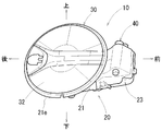
- FIGS. 1 to 12 An inlet box assembly for a vehicle according to an embodiment of the present invention will be described with reference to FIGS. 1 to 12.
- a vehicle having a battery that can be charged by an external power source such as an electric vehicle (EV) or a plug-in hybrid electric vehicle (PHEV), is connected to a power supply side connector when the battery is charged.
- a charging connector 50 is provided.
- the charging connector 50 is accommodated in the resin inlet box 20.
- the inlet box 20 constitutes a part of the assembled resin inlet box assembly 10 (hereinafter simply referred to as an assembly).
- the assembly 10 is attached to a predetermined position on the side surface of the outer panel 2 of the vehicle.
- front and rear, left and right, and top and bottom mean front and rear, left and right, and top and bottom of the vehicle, respectively.
- the assembly 10 includes a resin inlet box 20 having an opening 22, a resin lid 30 (lid) that opens and closes the opening 22 of the inlet box 20, and an inlet box 20. And a hinge mechanism 40 that rotatably connects the lid 30.
- the inlet box 20 includes a box main body portion 21 that accommodates the charging connector 50, and an overhang portion 23 that projects forward from the front side surface of the box main body portion 21.
- the box body 21 is formed in a substantially cup shape.
- the overhang portion 23 is formed in a substantially square bag shape (see FIG. 2) opened on the box body portion 21 side.
- a lighting fixture 27 that illuminates the charging connector 50 is provided on the upper side surface in the box body 21.
- the lighting fixture 27 includes a switch 28 that switches on and off the lighting fixture 27.
- a pressing mechanism 60 push lifter
- a floor surface opening 21 h through which a cable (not shown) connected to the charging connector 50 accommodated in the box body 21 is passed is formed at the bottom of the box body 21. ing.
- a circular flange portion 21 f is formed on the periphery of the opening 22 of the inlet box 20.
- a rubber seal 21e is attached along the periphery of the flange portion 21f.
- a bolt 215 for attaching the inlet box 20 to the outer panel 2 of the vehicle is formed on the back side of the flange portion 21 f so as to protrude substantially at right angles to the back surface of the flange portion 21 f. .
- the bolts 215 are provided at intervals of about 90 ° in the circumferential direction of the flange portion 21f so that two bolts 215 are arranged on each of the upper side and the lower side with respect to the box body portion 21.
- the outer panel 2 of the vehicle is formed with a circular recess 2k in which the lid 30 of the assembly 10 is accommodated.
- a substantially cross-shaped hole 2j into which the inlet box 20 is inserted is formed at the bottom of the recess 2k.
- a bolt hole 2b through which each bolt 215 provided in the flange portion 21f of the inlet box 20 is inserted is formed at the peripheral edge 2f of the hole 2j, that is, at the bottom of the recess 2k. Yes.
- the inlet box 20 In order to attach the inlet box 20 to the vehicle, first, the inlet box 20 is inserted into the hole 2j of the outer panel 2, and the four bolts 215 of the inlet box 20 are inserted into the bolt holes of the outer panel 2 as shown in FIG. Pass 2b. Next, the nut N is fastened to each bolt 215 from the inner side of the outer panel 2.
- the lid 30 includes a disc-shaped lid body 32 and a plane U-shaped lever 35 that supports the lid body 32.
- the lid body 32 is set to have an outer diameter that is substantially equal to the flange portion 21 f of the inlet box 20, and is configured to be received in the circular recess 2 k of the outer panel 2. ing.
- the lid body 32 closes the opening 22 of the inlet box 20 while being arranged coaxially with the flange portion 21 f of the inlet box 20.
- the lid body 32 is configured by combining the front surface plate portion 32f and the back surface plate portion 32u.
- a cover portion 32c of the charging connector 50 is formed at the center position of the back plate portion 32u.
- the lever 35 is accommodated in the overhang portion 23 of the inlet box 20 so that the lid 30 is allowed to rotate.
- the rotation free end side of the lever 35 is connected to the front end portion of the back plate portion 32 u of the lid body 32.
- the hinge mechanism 40 is a mechanism for connecting the lid 30 to the inlet box 20 so as to be able to rotate substantially horizontally.
- the hinge mechanism 40 includes a spring (not shown), and can hold the lid 30 in the fully closed position or the fully open position by the biasing force of the spring.
- the hinge mechanism 40 includes a hinge pin 41.
- An upper bearing portion 23j through which each end portion of the hinge pin 41 is passed and a lower bearing portion (not shown) are formed on the upper wall portion and the lower wall portion on the right side of the front end in the overhang portion 23 of the inlet box 20, respectively. ing.
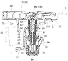
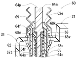
- the pressing mechanism 60 presses the rotation free end side of the cover 30 from the inlet box 20 as shown in FIGS. 7 and 11, and the switch 28 of the lighting fixture 27 (see FIG. 4). To turn on.
- the pressing mechanism 60 includes a pressing mechanism main body 61 and an operation unit 70 of the switch 28.
- the pressing mechanism main body 61 includes a guide cylinder 62 attached to the box main body 21 in a state perpendicular to the closed lid main body 32 as shown in FIGS. 8 and 11.
- the guide cylinder 62 includes an outer cylinder 62t and an inner cylinder 62e that are fitted in the axial direction. One end side of the outer cylinder 62t is fixed to the box body 21.
- the shaft member 64 is accommodated in the guide tube 62 so as to be slidable in the axial direction.
- the shaft member 64 includes a lid pressing shaft 64p protruding from an opening on the inner cylinder 62e side (upper opening in the figure) and an opening on the outer cylinder 62t side (in the figure).
- a switch pressing shaft 64s protruding from the lower opening).
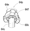
- the lid pressing shaft 64p includes a shaft main body 64m, a flange 64f, and a small-diameter connecting shaft 64c.
- the shaft portion main body 64m, the flange portion 64f, and the small-diameter connecting shaft portion 64c are provided coaxially.
- the connecting shaft portion 64c of the lid pressing shaft 64p is fitted into the connecting hole 64h of the switch pressing shaft 64s, and both the pressing shafts 64p and 64s are coaxially connected.
- the pressing mechanism main body 61 is provided with a bellows-shaped protective cover 69 that covers the protruding portion of the lid pressing shaft 64p while preventing the movement of the shaft member 64.
- a coil spring 65 is mounted around the switch pressing shaft 64s of the shaft member 64 in the guide cylinder 62 as shown in FIGS.
- the coil spring 65 biases the shaft member 64 so as to protrude from the opening (upper opening) of the guide tube 62 on the inner tube 62e side.
- a regulating mechanism 68 is provided between the inner cylinder 62e of the guide cylinder 62 and the lid pressing shaft 64p of the shaft member 64.
- the regulation mechanism 68 can regulate the pressing operation of the lid pressing shaft 64p and can release the regulation.
- the restricting mechanism 68 includes a ring member 68w that is rotatably mounted around the connecting shaft portion 64c of the lid pressing shaft 64p.
- a corrugated inclined surface 68k is formed on one surface (the lower surface in FIG. 12) of the flange portion 64f of the lid pressing shaft 64p.
- An inclined surface (not shown) that can slide along the corrugated inclined surface 68k of the lid pressing shaft 64p is formed on one end surface (upper surface in FIG. 12) of the ring member 68w in the axial direction.
- a guide groove 68m and an engagement groove 68s are formed on the inner peripheral surface of the inner cylinder 62e of the guide cylinder 62.
- the guide groove 68m is formed from one end to the other end in the axial direction of the inner cylinder 62e, and the engagement groove 68s is formed at one end of the inner cylinder 62e (the central portion of the guide cylinder 62).
- the ring member 68w includes an outer peripheral claw (not shown) on the outer peripheral surface. The outer peripheral claw can be fitted into either the guide groove 68m or the engagement groove 68s.
- FIG. 8 shows a state in which the outer peripheral claw is engaged with the engaging groove 68s
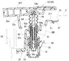
- FIG. 12 shows a state in which the outer peripheral claw is engaged with the guide groove 68m.
- the guide grooves 68m and the engagement grooves 68s are alternately formed at a constant angular interval. Each time the ring member 68w rotates by a certain angle, the outer peripheral claw of the ring member 68w is alternately engaged with the guide groove 68m or the engagement groove 68s.
- the shaft member 64 moves together with the ring member 68w and protrudes from the guide tube 62 in the direction of pressing the lid 30.
- the pressing mechanism main body 61 is held in a state in which the shaft member 64 protrudes (see FIG. 11).
- the operation unit 70 of the switch 28 includes a housing 72 and a switch operation lever 74 (movable unit) that can move in the housing 72.
- the housing 72 is attached to the other end side of the guide cylinder 62 (outer cylinder 62t) located on the back side of the inlet box 20.
- the switch operation lever 74 is connected to the switch pressing shaft 64s. Specifically, the switch operation lever 74 is urged by a spring provided between the housing 72 and the switch operation lever 74 as shown in FIGS.
- the operator To open the lid 30 of the assembly 10, the operator first presses the lid 30 in the closing direction, and pushes the shaft member 64 of the pressing mechanism 60 (the pressing mechanism main body 61) with the lid 30. As a result, the outer peripheral claw of the ring member 68w is disengaged from the engagement groove 68s of the inner cylinder 62e. As a result, the ring member 68w is rotated by a constant angle by the action of the inclined surface 68k of the shaft member 64, and the outer peripheral claw of the ring member 68w is aligned with the position of the guide groove 68m of the inner cylinder 62e.
- the outer peripheral claw of the ring member 68 w is moved along the guide groove 68 m by the biasing force of the coil spring 65, and the shaft member 64 is moved from the guide cylinder 62 to the lid 30. It protrudes in the direction which presses (refer FIG.7 and FIG.11).
- the lid 30 is opened by a certain amount, the switch 28 is turned on, and the lighting fixture 27 is turned on. In this state, the lid 30 can be opened to the fully open position. Further, since the lighting fixture 27 is turned on, it becomes easy to connect the power supply side connector (not shown) to the charging connector 50 even in a dark position.
- the operator To close the lid 30 of the assembly 10, the operator first closes the fully opened lid 30 to a position near the fully closed position in FIG. 11 against the biasing force of a spring (not shown) of the hinge mechanism 40. Next, the operator presses the lid 30 in the closing direction and pushes the shaft member 64 by the lid 30. As a result, the outer peripheral claw of the ring member 68w is disengaged from the guide groove 68m of the inner cylinder 62e. Thereby, the ring member 68w is rotated by a fixed angle by the action of the inclined surface 68k of the shaft member 64, and the outer peripheral claw of the ring member 68w is aligned with the position of the engagement groove 68s of the inner cylinder 62e.
- the outer peripheral claw of the ring member 68 w is engaged with the engagement groove 68 s by the biasing force of the coil spring 65.
- the switch 28 is turned off and the lighting fixture 27 is turned off.
- the lid 30 is held in the fully closed position by a biasing force of a spring (not shown) of the hinge mechanism 40.
- the assembly 10 includes the inlet box 20 having the opening 22 attached to the outer panel 2 of the vehicle, the lid 30 that opens and closes the opening 22 of the inlet box 20, and the hinge that connects the lid 30 to the inlet box 20. And a mechanism 40. Further, the assembly 10 includes a pressing mechanism 60 that presses the lid 30 from the inlet box 20 in the opening direction, a lighting fixture 27 provided in the inlet box 20, and a lighting fixture 27 that is turned on by an on operation and a lighting fixture that is turned off. And a switch 28 for turning off 27. The switch 28 is turned on in conjunction with the operation of the pressing mechanism 60 pressing the lid 30 in the opening direction, and is turned off in conjunction with the operation of closing the lid 30 and pushing the pressing mechanism 60.
- the lid 30 when an operation related to the inlet box 20 such as a charging operation is performed, an operator touches the lid 30 to perform an opening operation, so that the pressing mechanism 60 presses the lid 30 in the opening direction and the switch 28 of the lighting fixture 27. Is turned on, the lighting fixture 27 in the inlet box 20 is turned on only when work is performed. Further, when the work is completed and the operator closes the lid 30, the lighting fixture 27 is turned off. Therefore, the lighting time of the lighting fixture 27 is minimized, and battery power is not wasted.
- the switch 28 has a movable part that is turned on and off.
- the pressing mechanism 60 includes a shaft member 64, a guide tube 62, and a spring 65.
- the shaft member 64 presses the lid 30 with one end portion in the axial direction (lid pressing shaft 64p) and presses the movable portion (switch operation lever 74) of the switch 28 with the other end portion in the axial direction (switch pressing shaft 64s).
- the guide cylinder 62 is attached to the inlet box 20 and supports the shaft member 64 so as to be slidable in the axial direction.
- the spring 65 urges the shaft member 64 in the pressing direction of the lid 30 with respect to the guide tube 62.
- the pressing mechanism 60 has a regulation structure 68 (regulation structure).
- the restricting mechanism 68 restricts the pressing operation of the shaft member 64 when the shaft member is pushed to a predetermined position against the biasing force of the spring 65 when the lid 30 is closed. Further, the restriction structure 68 releases the restriction of the pressing operation of the shaft member 64 when the shaft member 64 is pushed from the predetermined position when the cover member 30 is pressed in the closing direction from the position where the cover 30 is closed when the cover 30 is opened. Thereby, since the shaft member 64 presses the lid 30 only when the lid 30 is opened, the lid opening operation is facilitated.
- a charging connector to which a power supply side connector is connected when charging the battery of the vehicle is provided, so that the above-described effects can be obtained during the charging operation.
- the lid pressing shaft 64p and the switch pressing shaft 64s constituting the shaft member 64 are not only separated as in the present embodiment, but the lid pressing shaft 64p and the switch pressing shaft 64s can be integrally formed. .
- the assembly 10 may include an oil filler port instead of the charging connector 50.
Landscapes
- Engineering & Computer Science (AREA)
- Mechanical Engineering (AREA)
- Transportation (AREA)
- Sustainable Energy (AREA)
- Life Sciences & Earth Sciences (AREA)
- Sustainable Development (AREA)
- Power Engineering (AREA)
- Chemical & Material Sciences (AREA)
- Combustion & Propulsion (AREA)
- Cooling, Air Intake And Gas Exhaust, And Fuel Tank Arrangements In Propulsion Units (AREA)
- Electric Propulsion And Braking For Vehicles (AREA)
- Hybrid Electric Vehicles (AREA)
- Arrangement Or Mounting Of Propulsion Units For Vehicles (AREA)
Abstract
L'invention porte sur un ensemble boîte d'entrée de véhicule. Un ensemble (10) comprend : une boîte d'entrée (20) présentant une ouverture (22) qui est fixée à un panneau extérieur (2) du véhicule, une trappe (30) servant à ouvrir/fermer l'ouverture (22) de la boîte d'entrée (20) ; et un mécanisme d'articulation (40) servant à articuler la trappe (30) à la boîte d'entrée (20). L'ensemble (10) comprend en outre : un mécanisme de pression (60) servant à presser la trappe (30) dans le sens de l'ouverture en partant de l'intérieur de la boîte d'entrée (20) ; un dispositif d'éclairage (27) disposé à l'intérieur de la boîte d'entrée (20) ; et un interrupteur (28) servant à allumer le dispositif d'éclairage (27) au moyen d'une manœuvre de mise en circuit et à éteindre le dispositif d'éclairage (27) au moyen d'une manœuvre de mise hors circuit. Le commutateur (28) exécute une opération de mise en circuit lorsqu'il est soumis à une opération dans laquelle le mécanisme de pression (60) pousse la trappe (30) dans le sens de l'ouverture et il exécute une opération de mise hors circuit lorsqu'il est soumis à une opération dans laquelle la trappe (30) est ouverte et le mécanisme de pression (60) est comprimé.
Applications Claiming Priority (2)
| Application Number | Priority Date | Filing Date | Title |
|---|---|---|---|
| JP2011-115780 | 2011-05-24 | ||
| JP2011115780A JP2012240645A (ja) | 2011-05-24 | 2011-05-24 | 車両のインレットボックスアッセンブリ |
Publications (1)
| Publication Number | Publication Date |
|---|---|
| WO2012161087A1 true WO2012161087A1 (fr) | 2012-11-29 |
Family
ID=47217165
Family Applications (1)
| Application Number | Title | Priority Date | Filing Date |
|---|---|---|---|
| PCT/JP2012/062662 Ceased WO2012161087A1 (fr) | 2011-05-24 | 2012-05-17 | Ensemble boîte d'entrée de véhicule |
Country Status (2)
| Country | Link |
|---|---|
| JP (1) | JP2012240645A (fr) |
| WO (1) | WO2012161087A1 (fr) |
Cited By (7)
| Publication number | Priority date | Publication date | Assignee | Title |
|---|---|---|---|---|
| DE102016004557A1 (de) * | 2016-04-15 | 2017-10-19 | GM Global Technology Operations LLC (n. d. Gesetzen des Staates Delaware) | Klappe mit einem Anzeigemittel |
| US20210016658A1 (en) * | 2019-07-15 | 2021-01-21 | Illinois Tool Works Inc. | Charging or fueling recess and method for the production thereof |
| WO2021071704A1 (fr) * | 2019-10-10 | 2021-04-15 | Illinois Tool Works Inc. | Évidement de charge ou de ravitaillement en carburant |
| US11124995B2 (en) * | 2018-02-28 | 2021-09-21 | Nifco Inc. | Push-lifter for vehicle |
| EP4140793A1 (fr) * | 2021-08-27 | 2023-03-01 | Reich GmbH Regel- und Sicherheitstechnik | Dispositif clapet pour un véhicule |
| CN116783090A (zh) * | 2021-01-27 | 2023-09-19 | 浙江智马达智能科技有限公司 | 一种汽车充电口盖结构及汽车 |
| JP2023146184A (ja) * | 2022-03-29 | 2023-10-12 | 本田技研工業株式会社 | 燃料タンクの照明装置 |
Families Citing this family (7)
| Publication number | Priority date | Publication date | Assignee | Title |
|---|---|---|---|---|
| WO2014045831A1 (fr) * | 2012-09-19 | 2014-03-27 | 日産自動車株式会社 | Structure de charge externe d'un véhicule électrique |
| JP5920146B2 (ja) * | 2012-09-27 | 2016-05-18 | 豊田合成株式会社 | フューエルインレットボックスのシール構造 |
| JP7086915B2 (ja) * | 2019-10-24 | 2022-06-20 | 株式会社ニフコ | リッド装置 |
| KR102327482B1 (ko) * | 2020-09-11 | 2021-11-17 | 대동하이렉스 주식회사 | 자동차 연료 주입구 도어 개폐장치 |
| KR20230087731A (ko) * | 2021-12-10 | 2023-06-19 | 에스엘 주식회사 | 충전 포트 도어 |
| FR3139515A1 (fr) * | 2022-09-08 | 2024-03-15 | Psa Automobiles Sa | Vehicule automobile avec prise de recharge de batterie de traction sur un panneau arriere de custode |
| CN122014075A (zh) | 2024-11-12 | 2026-05-12 | 矢崎总业株式会社 | 盖机构和充电口 |
Citations (6)
| Publication number | Priority date | Publication date | Assignee | Title |
|---|---|---|---|---|
| JPH03121920U (fr) * | 1990-03-27 | 1991-12-12 | ||
| JPH06290836A (ja) * | 1993-03-31 | 1994-10-18 | Sumitomo Wiring Syst Ltd | 電気自動車における充電用コネクタ |
| JP2004281259A (ja) * | 2003-03-17 | 2004-10-07 | Alps Electric Co Ltd | プッシュスイッチ装置 |
| WO2007122835A1 (fr) * | 2006-04-25 | 2007-11-01 | Nifco Inc. | Dispositif de poussée |
| JP2009146711A (ja) * | 2007-12-13 | 2009-07-02 | Mitsubishi Motors Corp | 充電コネクタの取付構造 |
| JP2011098632A (ja) * | 2009-11-05 | 2011-05-19 | Suzuki Motor Corp | 充電器冷却構造および車載機器冷却システム |
-
2011
- 2011-05-24 JP JP2011115780A patent/JP2012240645A/ja not_active Withdrawn
-
2012
- 2012-05-17 WO PCT/JP2012/062662 patent/WO2012161087A1/fr not_active Ceased
Patent Citations (6)
| Publication number | Priority date | Publication date | Assignee | Title |
|---|---|---|---|---|
| JPH03121920U (fr) * | 1990-03-27 | 1991-12-12 | ||
| JPH06290836A (ja) * | 1993-03-31 | 1994-10-18 | Sumitomo Wiring Syst Ltd | 電気自動車における充電用コネクタ |
| JP2004281259A (ja) * | 2003-03-17 | 2004-10-07 | Alps Electric Co Ltd | プッシュスイッチ装置 |
| WO2007122835A1 (fr) * | 2006-04-25 | 2007-11-01 | Nifco Inc. | Dispositif de poussée |
| JP2009146711A (ja) * | 2007-12-13 | 2009-07-02 | Mitsubishi Motors Corp | 充電コネクタの取付構造 |
| JP2011098632A (ja) * | 2009-11-05 | 2011-05-19 | Suzuki Motor Corp | 充電器冷却構造および車載機器冷却システム |
Cited By (10)
| Publication number | Priority date | Publication date | Assignee | Title |
|---|---|---|---|---|
| DE102016004557A1 (de) * | 2016-04-15 | 2017-10-19 | GM Global Technology Operations LLC (n. d. Gesetzen des Staates Delaware) | Klappe mit einem Anzeigemittel |
| US11124995B2 (en) * | 2018-02-28 | 2021-09-21 | Nifco Inc. | Push-lifter for vehicle |
| US20210016658A1 (en) * | 2019-07-15 | 2021-01-21 | Illinois Tool Works Inc. | Charging or fueling recess and method for the production thereof |
| US11945300B2 (en) * | 2019-07-15 | 2024-04-02 | Illinois Tool Works Inc. | Charging or fueling recess and method for the production thereof |
| WO2021071704A1 (fr) * | 2019-10-10 | 2021-04-15 | Illinois Tool Works Inc. | Évidement de charge ou de ravitaillement en carburant |
| CN116783090A (zh) * | 2021-01-27 | 2023-09-19 | 浙江智马达智能科技有限公司 | 一种汽车充电口盖结构及汽车 |
| EP4286256A4 (fr) * | 2021-01-27 | 2024-11-06 | Zhejiang Smart Intelligence Technology Co., Ltd. | Structure de couvercle de prise de recharge d'automobile et automobile |
| EP4140793A1 (fr) * | 2021-08-27 | 2023-03-01 | Reich GmbH Regel- und Sicherheitstechnik | Dispositif clapet pour un véhicule |
| JP2023146184A (ja) * | 2022-03-29 | 2023-10-12 | 本田技研工業株式会社 | 燃料タンクの照明装置 |
| JP7487249B2 (ja) | 2022-03-29 | 2024-05-20 | 本田技研工業株式会社 | 燃料タンクの照明装置 |
Also Published As
| Publication number | Publication date |
|---|---|
| JP2012240645A (ja) | 2012-12-10 |
Similar Documents
| Publication | Publication Date | Title |
|---|---|---|
| JP2012240645A (ja) | 車両のインレットボックスアッセンブリ | |
| US11519203B2 (en) | Actuation device | |
| US10328792B2 (en) | Lid device | |
| KR101577548B1 (ko) | 충전 포트 로크 장치 | |
| WO2012157489A1 (fr) | Structure de montage d'une boîte d'entrée de véhicule | |
| CN108340974B (zh) | 充电盖单元 | |
| JP2014110205A (ja) | 充電ポートロック装置 | |
| US20200361057A1 (en) | Rotating tool | |
| JP2015207565A (ja) | 電動車両の充電ポート装置 | |
| JP2015074976A (ja) | ラッチ装置 | |
| US20120282806A1 (en) | Electric power connector | |
| US11426838B2 (en) | Rotating tool | |
| CN219569855U (zh) | 汽车车身盖的控制机构 | |
| JP6682364B2 (ja) | ハウジングユニット及び開閉体のロック装置 | |
| WO2013054646A1 (fr) | Dispositif de verrouillage de port de charge | |
| US20160250924A1 (en) | Reaction force output device | |
| JP2024532087A (ja) | 自動車用途の為のロック用アクチュエータ | |
| JP6447370B2 (ja) | 車両用の蓋体開閉装置 | |
| WO2018188552A1 (fr) | Mécanisme de couvercle d'ouverture de remplissage de compartiment énergétique et véhicule le comprenant | |
| US12590478B2 (en) | Lid opening/closing structure | |
| JP2010106438A (ja) | 車両用リッドロック装置 | |
| JP7800382B2 (ja) | リッド開閉装置 | |
| KR20240017191A (ko) | 전기자동차용 아웃렛 충전기 | |
| US20240263506A1 (en) | Lid opening/closing device | |
| CN209569386U (zh) | 一种电动执行器及其反馈开关组件 |
Legal Events
| Date | Code | Title | Description |
|---|---|---|---|
| 121 | Ep: the epo has been informed by wipo that ep was designated in this application |
Ref document number: 12789892 Country of ref document: EP Kind code of ref document: A1 |
|
| DPE1 | Request for preliminary examination filed after expiration of 19th month from priority date (pct application filed from 20040101) | ||
| NENP | Non-entry into the national phase |
Ref country code: DE |
|
| 122 | Ep: pct application non-entry in european phase |
Ref document number: 12789892 Country of ref document: EP Kind code of ref document: A1 |