WO2012161332A1 - Dispositif générateur d'énergie solaire concentrée - Google Patents
Dispositif générateur d'énergie solaire concentrée Download PDFInfo
- Publication number
- WO2012161332A1 WO2012161332A1 PCT/JP2012/063568 JP2012063568W WO2012161332A1 WO 2012161332 A1 WO2012161332 A1 WO 2012161332A1 JP 2012063568 W JP2012063568 W JP 2012063568W WO 2012161332 A1 WO2012161332 A1 WO 2012161332A1
- Authority
- WO
- WIPO (PCT)
- Prior art keywords
- photoelectric conversion
- optical axis
- lens
- light
- solar power
- Prior art date
- Legal status (The legal status is an assumption and is not a legal conclusion. Google has not performed a legal analysis and makes no representation as to the accuracy of the status listed.)
- Ceased
Links
Images






Classifications
-
- G—PHYSICS
- G02—OPTICS
- G02B—OPTICAL ELEMENTS, SYSTEMS OR APPARATUS
- G02B19/00—Condensers, e.g. light collectors or similar non-imaging optics
- G02B19/0004—Condensers, e.g. light collectors or similar non-imaging optics characterised by the optical means employed
- G02B19/0009—Condensers, e.g. light collectors or similar non-imaging optics characterised by the optical means employed having refractive surfaces only
- G02B19/0014—Condensers, e.g. light collectors or similar non-imaging optics characterised by the optical means employed having refractive surfaces only at least one surface having optical power
-
- G—PHYSICS
- G02—OPTICS
- G02B—OPTICAL ELEMENTS, SYSTEMS OR APPARATUS
- G02B19/00—Condensers, e.g. light collectors or similar non-imaging optics
- G02B19/0033—Condensers, e.g. light collectors or similar non-imaging optics characterised by the use
- G02B19/0038—Condensers, e.g. light collectors or similar non-imaging optics characterised by the use for use with ambient light
-
- H—ELECTRICITY
- H10—SEMICONDUCTOR DEVICES; ELECTRIC SOLID-STATE DEVICES NOT OTHERWISE PROVIDED FOR
- H10F—INORGANIC SEMICONDUCTOR DEVICES SENSITIVE TO INFRARED RADIATION, LIGHT, ELECTROMAGNETIC RADIATION OF SHORTER WAVELENGTH OR CORPUSCULAR RADIATION
- H10F77/00—Constructional details of devices covered by this subclass
- H10F77/40—Optical elements or arrangements
- H10F77/42—Optical elements or arrangements directly associated or integrated with photovoltaic cells, e.g. light-reflecting means or light-concentrating means
- H10F77/488—Reflecting light-concentrating means, e.g. parabolic mirrors or concentrators using total internal reflection
-
- H—ELECTRICITY
- H10—SEMICONDUCTOR DEVICES; ELECTRIC SOLID-STATE DEVICES NOT OTHERWISE PROVIDED FOR
- H10F—INORGANIC SEMICONDUCTOR DEVICES SENSITIVE TO INFRARED RADIATION, LIGHT, ELECTROMAGNETIC RADIATION OF SHORTER WAVELENGTH OR CORPUSCULAR RADIATION
- H10F77/00—Constructional details of devices covered by this subclass
- H10F77/40—Optical elements or arrangements
- H10F77/42—Optical elements or arrangements directly associated or integrated with photovoltaic cells, e.g. light-reflecting means or light-concentrating means
- H10F77/492—Spectrum-splitting means, e.g. dichroic mirrors
-
- Y—GENERAL TAGGING OF NEW TECHNOLOGICAL DEVELOPMENTS; GENERAL TAGGING OF CROSS-SECTIONAL TECHNOLOGIES SPANNING OVER SEVERAL SECTIONS OF THE IPC; TECHNICAL SUBJECTS COVERED BY FORMER USPC CROSS-REFERENCE ART COLLECTIONS [XRACs] AND DIGESTS
- Y02—TECHNOLOGIES OR APPLICATIONS FOR MITIGATION OR ADAPTATION AGAINST CLIMATE CHANGE
- Y02E—REDUCTION OF GREENHOUSE GAS [GHG] EMISSIONS, RELATED TO ENERGY GENERATION, TRANSMISSION OR DISTRIBUTION
- Y02E10/00—Energy generation through renewable energy sources
- Y02E10/50—Photovoltaic [PV] energy
- Y02E10/52—PV systems with concentrators
Definitions
- the present invention relates to a concentrating solar power generation device.
- FIG. 1 shows a cross-sectional view of a concentrating solar power generation device 1.
- the concentrating solar power generation device 1 includes a condensing lens 2 and a stacked photoelectric conversion cell 3.
- the stacked photoelectric conversion cell 3 has a configuration in which a plurality of individual photoelectric conversion cells 4 to 6 having different sensitivity wavelength bands are stacked.
- Incident light (sunlight) 7 incident on the concentrating solar power generation device 1 enters the condensing lens 2 in parallel with the optical axis 8 of the condensing lens 2. Then, the transmitted light 9 transmitted through the condenser lens 2 is collected and focused on the light receiving surface 10 perpendicular to the optical axis 8.
- the condensing lens 2 only one surface is the lens curved surface 11, and the sunlight incident surface that is the opposite surface is a flat surface.
- both surfaces of the condenser lens 2 may be lens curved surfaces.
- the condenser lens 2 may be a Fresnel lens.
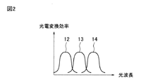
- FIG. 2 shows the light wavelength dependency of the photoelectric conversion efficiency of the stacked photoelectric conversion cell 3.
- Curves 12 to 14 in the graph of FIG. 2 indicate the optical wavelength dependency of the photoelectric conversion efficiency of the individual photoelectric conversion cells 4 to 6, respectively.
- the light receiving area is reduced by condensing sunlight with a condensing lens as in the concentrating solar power generation device 1.
- a photoelectric conversion method is used.
- the concentrating solar power generation device 1 as the light incident from the light receiving surface 10 of the stacked photoelectric conversion cell 3 passes through the plurality of individual photoelectric conversion cells, it is scattered, absorbed, and reflected at the boundary surface. May be lost. Therefore, there arises a problem that the power generation efficiency does not increase.
- a concentrating solar power generation apparatus using chromatic aberration has been proposed.
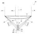
- FIG. 3 shows a cross-sectional view of the concentrating solar power generation device described in Patent Document 1.
- the concentrating solar power generation device 20 includes a condensing lens 21 and a stacked photoelectric conversion cell 22.
- the stacked photoelectric conversion cell 22 has a configuration in which a plurality of individual photoelectric conversion cells 23 to 25 having different sensitivity wavelength bands are stacked.
- Incident light 26 incident on the concentrating solar power generation device 20 is incident on the condensing lens 21 in parallel with the optical axis 27 of the condensing lens 21.
- the transmitted light 28 that has passed through the condenser lens 21 is focused at different positions on the optical axis 27 for each wavelength because of the dispersion characteristics of the lens, which have different refractive indices depending on the wavelength. This is a phenomenon called axial chromatic aberration.
- FIG. 3 as an example, light beams of three different wavelength bands, a short wavelength band light 29, a medium wavelength band light 30, and a long wavelength band light 31 are illustrated. Then, by arranging the individual photoelectric conversion cells 23 to 25 suitable for photoelectric conversion in each wavelength band at the focal position of each wavelength band, all light is most transmitted from the surface (light receiving surface) of the stacked photoelectric conversion cell 22. Photoelectric conversion can be performed at a close junction.
- each of the individual photoelectric conversion cells 23 to 25 has a cylindrical light receiving surface 32 around the optical axis 27.
- the light receiving surface 32 faces outward with respect to the optical axis 27.
- the condensing lens 21 only the single side
- surface is the lens curved surface 33, and the sunlight incident surface which is the surface of the other side is a plane.
- FIG. 4 is a perspective view of the concentrating solar power generation device 20.
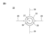
- FIG. 5 is a top view of the stacked photoelectric conversion cell 22 included in the concentrating solar power generation device 20.
- a base 34 is disposed around the optical axis 27, and a joint 35 for performing photoelectric conversion is disposed around the base 34.
- the outermost periphery of the stacked photoelectric conversion cell 22 is the light receiving surface 32.
- the transmitted light 28 enters the light receiving surface 32 from the outside.
- the transmitted light 28 a of the incident light 26 a close to the optical axis 27 enters the light receiving surface 32 with a small incident angle I, as shown in FIG. 3. Therefore, most of the transmitted light 28a is reflected as reflected light 28b. Thereby, the problem that the photoelectric conversion efficiency of a solar power generation device will fall arises.
- patent document 1 as shown in FIG. 6, the example using the cone-shaped laminated photoelectric conversion cell 36 is also disclosed.
- the stacked photoelectric conversion cell 36 has a configuration in which individual photoelectric conversion cells 37 to 39 are stacked. In this case, the incident angle I of the transmitted light 28a of the incident light 26a close to the optical axis 27 with respect to the light receiving surface 40 is larger than the incident angle I shown in FIG. Therefore, reflection of the transmitted light 28a can be suppressed.
- An object of this invention is to provide the concentrating solar power generation device which can obtain high photoelectric conversion efficiency in view of the said problem.
- a concentrating solar power generation device includes a condensing lens and a cylindrical photoelectric conversion cell, and the condensing lens is incident along the optical axis of the condensing lens.
- the incident light is condensed on the circumference of a circle having a radius r centered on the optical axis, and the light receiving surface of the photoelectric conversion cell is the inner peripheral surface of the photoelectric conversion cell, and is arranged along the circumference. Is done.
- a cross-section along the optical axis of the condensing lens and a predetermined region of the cross-section along the optical axis of the point-shaped condensing lens that collects incident light in a dot shape are similar.
- the incident light that is shaped and incident along the optical axis of the condensing lens is condensed on the circumference of a circle with a radius r centered on the optical axis of the condensing lens.
- the photoelectric conversion cell in the present invention has a cylindrical shape, has a light receiving surface on the inner peripheral surface of the cylindrical shape, and is arranged on the circumference of a circle on which light is collected by a condenser lens.
- Sectional drawing of the concentrating solar power generation device relevant to this invention is shown.
- the graph which showed the optical wavelength dependence of the photoelectric conversion efficiency of a photoelectric conversion cell is shown.
- Sectional drawing of the concentrating solar power generation device relevant to this invention is shown.
- the perspective view of the concentrating solar power generation device relevant to this invention is shown.
- the top view of the lamination photoelectric conversion cell which the concentrating solar power generation device relevant to this invention has is shown.
- Sectional drawing of the concentrating solar power generation device relevant to this invention is shown.
- Sectional drawing of the concentrating solar power generation device in the 1st Embodiment of this invention is shown.
- 1 is a cross-sectional view of a condenser lens according to a first embodiment of the present invention.
- FIG. 8A It is the figure which looked at the focus ring formed with the condensing lens in the 1st Embodiment of this invention from the upper surface of FIG. 8A.
- the structure of the photoelectric conversion cell in the 1st Embodiment of this invention is shown.
- Sectional drawing of the concentrating solar power generation device in the 2nd Embodiment of this invention is shown.
- vertical to the optical axis of a condensing lens of the photoelectric conversion cell in the 2nd Embodiment of this invention is shown.
- the perspective view of the photoelectric conversion cell in the 2nd Embodiment of this invention is shown.
- FIG. 2 shows a cross-sectional view of a condenser lens related to the present invention.
- Sectional drawing of the concentrating solar power generation device in the 3rd Embodiment of this invention is shown.
- the perspective view of the photoelectric conversion cell in the 3rd Embodiment of this invention is shown.
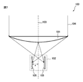
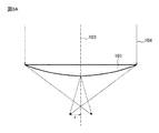
- FIG. 7 shows a cross-sectional view of the concentrating solar power generation device 100 according to the present embodiment along the optical axis of the condensing lens.
- the concentrating solar power generation device 100 includes a condensing lens 101 and a cylindrical photoelectric conversion cell 102.
- FIG. 8 shows the structure of the condenser lens 101.
- FIG. 8A shows a cross-sectional view of the condenser lens 101.
- FIG. 8B is a view of the focus ring formed by the condenser lens 101 as seen from the top surface of FIG. 8A.
- incident light 104 incident along the optical axis 103 of the condensing lens 101 is collected on the circumference of a circle having a radius r centering on the optical axis 103.
- FIG. 8B is a view of incident light 104 incident along the optical axis 103 of the condensing lens 101 is collected on the circumference of a circle having a radius r centering on the optical axis 103.
- the light receiving surface 105 of the photoelectric conversion cell 102 is an inner peripheral surface of the photoelectric conversion cell 102, and is arranged along a circumference of a circle having a radius r centering on the optical axis 103. .
- a perspective view of the photoelectric conversion cell 102 is shown in FIG. As shown in FIG. 7, the photoelectric conversion cell 102 is arranged such that the cylindrical central axis of the photoelectric conversion cell 102 is parallel to the optical axis 103 of the condenser lens 101.
- the incident light 104 incident on the condensing lens 101 can be condensed on the light receiving surface 105 of the photoelectric conversion cell 102. .
- FIG. 10 is a cross-sectional view of the concentrating solar power generation device 200 according to the present embodiment along the optical axis of the condensing lens.
- the concentrating solar power generation apparatus 200 includes a condensing lens 201 and a cylindrical photoelectric conversion cell 202.
- the condenser lens 201 separates the incident light 204 incident along the optical axis 203 of the condenser lens 201 into a plurality of wavelength bands. Then, the condensing lens 201 condenses the incident light 204 on the circumference of a circle having a radius r centered at a different position on the optical axis 203 for each of the plurality of wavelength bands.
- the photoelectric conversion cell 202 has a configuration in which a plurality of cylindrical individual photoelectric conversion cells 205 to 207 having different sensitivity wavelength bands are stacked.
- Each of the individual photoelectric conversion cells 205 to 207 is arranged on a circumference where the wavelength bands corresponding to the respective sensitivity wavelength bands are condensed.
- the light receiving surface 208 of the photoelectric conversion cell 202 is the inner peripheral surface of the photoelectric conversion cell 202 and is parallel to the optical axis 203 of the condenser lens 201. That is, the cylindrical central axis formed by the plurality of individual photoelectric conversion cells 205 to 207 is parallel to the optical axis 203 of the condenser lens 201.
- Incident light 204 from the sun is collected after passing through the condenser lens 201.
- the refractive index of light when passing through the condenser lens 201 depends on the light wavelength.
- the incident light 204 is separated into a plurality of wavelength bands, and chromatic aberration occurs.
- the transmitted light is divided into three wavelength light beams, that is, a short wavelength light beam 209, a medium wavelength light beam 210, and a long wavelength light beam 211.
- the transmitted light of the condensing lens 201 is not condensed at one point, but is condensed in a ring shape along the circumference of a circle with the optical axis 203 as the center. That is, the condensing lens 201 forms a focal ring by condensing transmitted light.
- the transmitted light of each wavelength forms a focus ring with a different position on the optical axis 203 as the center.
- the intersections of the short-wavelength rays 209A and 209a and the intersections of 209B and 209b indicate the cross-section of the focal ring formed by the short-wavelength rays 209.
- the intersection of the mid-wavelength rays 210A and 210a and the intersection of 210B and 210b indicate the cross-section of the focal ring formed by the mid-wavelength rays 210.
- the intersections of the long wavelength light beams 211A and 211a and the intersections of 211B and 211b indicate the cross section of the focal ring formed by the long wavelength light beams 211.
- the incident light 204 incident on the condenser lens 201 one of the light beams farthest from the optical axis 203 is a light beam 204A.
- the light rays 204A which are the light transmitted through the condenser lens 201, are the light rays in the respective wavelength bands of the transmitted light, which are referred to as the short wavelength band light ray 209A, the middle wavelength band light ray 210A, and the long wavelength band light ray 211A.
- an incident light beam at a position symmetrical to the light beam 204A with respect to the optical axis 203 is referred to as a light beam 204B.
- the light beams 204B are the light transmitted through the condenser lens 201, and the light beams in the respective wavelength bands of the transmitted light are referred to as short wavelength band light 209B, medium wavelength band light 210B, and long wavelength band light 211B.
- a light ray close to the light ray 204A is referred to as a light ray 204a.
- the light beams 204a are transmitted through the condenser lens 201, and the respective wavelength light beams of the transmitted light are referred to as a short wavelength band light beam 209a, a medium wavelength band light beam 210a, and a long wavelength band light beam 211a.
- a light ray close to the light ray 204B is designated as 204b.
- the light beams 204b are transmitted through the condenser lens 201, and the light beams in the respective wavelength bands of the transmitted light are referred to as short wavelength band light 209b, medium wavelength band light 210b, and long wavelength band light 211b. These are representative of some of the light rays.
- FIG. 10 shows a cross section of the individual photoelectric conversion cell 205 arranged along the focus ring of the short wavelength band light, a cross section of the individual photoelectric conversion cell 206 arranged along the focus ring of the medium wavelength band light, and a long wavelength.
- the cross section of the photoelectric conversion cell 207 arranged along the focus ring of the band is shown.
- the photoelectric conversion cell 202 has a cylindrical shape with the optical axis 203 as the center.
- the light receiving surface 208 is disposed on the inner peripheral surface of the photoelectric conversion cell 202 and faces the optical axis 203.
- FIG. 11 is a cross-sectional view of the photoelectric conversion cell 202 in a plane perpendicular to the optical axis 203.
- the light receiving surface 208 and the joint portion 216 that performs photoelectric conversion are arranged along the circumference of a circle centered on the optical axis 203. Further, the light receiving surface 208 faces the optical axis 203. Then, the transmitted light 212 transmitted through the condenser lens 201 enters the light receiving surface 208 toward the outside of the circumference of the photoelectric conversion cell 202. A cavity 213 is formed inside the light receiving surface 208.
- FIG. 12 is a perspective view of the photoelectric conversion cell 202.
- FIG. 13 is a sectional view of a condenser lens 300 related to the present invention.
- the condensing lens 300 is a condensing lens 300 that condenses incident light at one point. Incident light 301 incident on the condenser lens 300 passes through the condenser lens 300. The transmitted light is focused on the optical axis 302 of the condenser lens 300.
- the transmitted light which is the incident light 301 transmitted through the condenser lens 300, is separated for each wavelength by chromatic aberration generated in the condenser lens 300, and is focused at different positions on the optical axis 302.
- the short wavelength light ray 303, the medium wavelength light ray 304, and the long wavelength light ray 305 of the transmitted light are shown as representatives.
- the focal points 306 to 308 are point focal points of the light rays 303 to 305, respectively.
- the inclination of the contact surface 310 of the lens curved surface 309 within the range of the circle having the radius s from the optical axis 302 is defined as t (s). Note that.
- the tangent surface 310 is drawn as a tangent.
- the transmitted light in the condensing lens 201 in the present embodiment is condensed on the circumference of the radius r around the optical axis 203 to form a focus ring.
- the inclination of the contact surface 215 of the lens curved surface 214 at a radius R from the optical axis 203 is defined as T (R).
- the condensing lens 201 can be realized by forming a condensing lens having a lens curved surface having the relationship of the expression (1) with the lens curved surface 309 of the condensing lens 300 forming a point-like focus.
- a spherical lens is often used as the condenser lens 300 that forms a point-like focus.
- the lens curved surface of the spherical lens has a shape of a part of a spherical surface with a radius Z.
- s Z ⁇ sin (t) (hereinafter referred to as equation (2)) between s, t, and Z in FIG.
- This expression (2) defines the lens curved surface shape of the spherical lens.
- the fact that the condensing lens 201 and the condensing lens 300 have the relationship of the formula (1) is that the lens curved surface cross section in the region outside the circle of radius r from the optical axis 302 of the condensing lens 300. It means that the lens curved surface section of the condensing lens 201 has a similar shape.
- a focus ring having a radius r can be formed around the optical axis.
- the condenser lens 300 is a spherical lens.
- the transmitted light that has passed through the condenser lens 201 in this embodiment forms a focal ring having a finite radius (radius r) around the optical axis 203 of the condenser lens 201. Then, due to the chromatic aberration generated in the condenser lens 201, the focus ring is formed at a different position in the optical axis direction according to the wavelength. That is, the transmitted light as a whole forms a spectrally resolved cylindrical focus. And the individual photoelectric conversion cell suitable for photoelectric conversion of the wavelength band is arrange
- the light of all the wavelength bands is photoelectrically converted by the junction part nearest from the light-receiving surface of an individual photoelectric conversion cell. Therefore, the loss of light can be reduced as compared with the stacked photoelectric conversion cell as shown in FIG. 1 in which the transmitted light needs to pass through the photoelectric conversion cell.
- the angle between part of the transmitted light and the optical axis becomes small.
- the angle between the part of the transmitted light and the optical axis is referred to as a transmitted light angle. That is, the transmitted light angle of incident light near the optical axis of the condenser lens 21 is a value close to zero. That is, the transmitted light is substantially parallel to the optical axis 14.
- the incident angle of the transmitted light with respect to the light receiving surface of the photoelectric conversion cell becomes small, and reflection of the transmitted light tends to occur.
- the concentrating solar power generation device 20 shown in FIG. 3 most of the transmitted light is reflected by the surface of the light receiving surface parallel to the optical axis. Therefore, only a part of the transmitted light that has passed through the condenser lens 21 is used for photoelectric conversion, and there is a problem that the power generation efficiency does not increase.
- the condensing lens 201 of the present embodiment the transmitted light angle of incident light near the optical axis is large, and a certain size can be secured even with the minimum transmitted light angle (J in FIG. 10).
- the photoelectric conversion cell 202 has a structure in which three individual photoelectric conversion cells are stacked and arranged in the optical axis direction, but is not limited thereto. For example, a structure in which two individual photoelectric conversion cells are arranged may be employed. Alternatively, a structure in which four or more individual photoelectric conversion cells are arranged may be used.
- the wavelength band of transmitted light may be divided into an arbitrary number, and individual photoelectric conversion cells corresponding to the respective wavelength bands may be used.
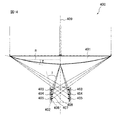
- the concentrating solar power generation device 400 in this embodiment includes a condensing lens 401 and a cylindrical photoelectric conversion cell 402. Note that the condensing lens 401 has the same structure as the condensing lens 201 in the second embodiment.
- the photoelectric conversion cell 402 has a configuration in which a plurality of cylindrical individual photoelectric conversion cells 403 to 405 having different sensitivity wavelength bands are arranged in the direction of the optical axis 409 of the condenser lens 401.
- the individual photoelectric conversion cells 403 to 405 are arranged on the circumference where the wavelength bands corresponding to the respective sensitivity wavelength bands are condensed.
- the light receiving surfaces 406 to 408 of the individual photoelectric conversion cells 403 to 405 are formed on the inner peripheral surfaces of the individual photoelectric conversion cells 403 to 405, respectively, and face the optical axis 409 of the condenser lens 401.
- Each of the light receiving surfaces 406 to 408 is inclined with respect to the optical axis 409 so as to approach the optical axis 409 as the distance from the focusing lens 401 increases. Note that the cylindrical central axis formed by the individual photoelectric conversion cells 403 to 405 is parallel to the optical axis 409 of the condenser lens 401.
- FIG. 15 is a perspective view of the photoelectric conversion cell 402 in the present embodiment.
- the light receiving surfaces 406 to 408 of the individual photoelectric conversion cells 403 to 405 have the shape of the side surface of the truncated cone.
- the transmitted light angle becomes larger compared to the case where the light receiving surfaces 406 to 408 are parallel to the optical axis 409. That is, when the photoelectric conversion cell 402 is used, the incident angle I of the transmitted light with respect to the light receiving surface becomes closer to 90 °, and reflection on the light receiving surface can be further suppressed.
- the optical axis is such that the light receiving surface of each individual photoelectric conversion cell approaches the optical axis of the condensing lens as the distance from the focusing lens increases. It is inclined with respect to. Therefore, compared with the concentrating solar power generation device 200 in the first embodiment, the incident angle of the transmitted light with respect to the light receiving surface can be made larger. Thereby, higher photoelectric conversion efficiency can be obtained.
- the number of individual photoelectric conversion cells to be stacked is not particularly limited.
- the condensing lenses 101, 201, and 401 shown in the first to third embodiments are all single-sided curved lenses having a lens curved surface only on one side, the present invention is not limited to this. That is, a double-sided curved lens having a lens curved surface on both sides or a Fresnel lens may be used as the condenser lens.
- a part or all of the above-described embodiment can be described as in the following supplementary notes, but is not limited thereto.
- a condensing lens and a cylindrical photoelectric conversion cell are provided, and the condensing lens is configured such that incident light incident along the optical axis of the condensing lens is centered on the optical axis.
- the light is condensed on the circumference of a circle having a radius r, and the light receiving surface of the photoelectric conversion cell is an inner peripheral surface of the photoelectric conversion cell, and is arranged along the circumference.
- Optical solar power generator. (Additional remark 2)
- the photoelectric conversion cell has a configuration in which a plurality of individual photoelectric conversion cells having different sensitivity wavelength bands are arranged in the optical axis direction, and each of the plurality of individual photoelectric conversion cells has a respective sensitivity. 2.
- the concentrating solar power generation device according to appendix 1, wherein the concentrating solar power generation device is disposed on the circumference where the wavelength band corresponding to the wavelength band is condensed.
- the said light-receiving surface is formed in parallel with the said optical axis,
- the light receiving surfaces of the plurality of individual photoelectric conversion cells are inclined with respect to the optical axis so as to approach the optical axis as the distance from the focusing lens increases. 2.
- the concentrating solar power generation device according to 2.
- condensing lens Comprising: The predetermined area
- a plurality of cylindrical individual photoelectric conversion cells having different sensitivity wavelength bands are arranged, and each of the plurality of individual photoelectric conversion cells has a wavelength band corresponding to each of the sensitivity wavelength bands.
- each light receiving surface of the plurality of individual photoelectric conversion cells is inclined with respect to a central axis of the cylindrical shape.
- each of the light receiving surfaces of the plurality of cylindrical individual photoelectric conversion cells is formed in parallel with an optical axis of the condenser lens.
- each of the light receiving surfaces of the plurality of cylindrical individual photoelectric conversion cells is inclined with respect to an optical axis of the condenser lens.
Landscapes
- Physics & Mathematics (AREA)
- General Physics & Mathematics (AREA)
- Optics & Photonics (AREA)
- Photovoltaic Devices (AREA)
- Mounting And Adjusting Of Optical Elements (AREA)
Abstract
La présente invention vise à pourvoir à un dispositif générateur d'énergie solaire concentrée apte à atteindre une efficacité élevée de conversion photoélectrique. Ce dispositif de génération d'énergie solaire concentrée comporte une lentille condensatrice et une cellule de conversion photoélectrique tubulaire, la lentille condensatrice concentre la lumière incidente le long de l'axe optique de la lentille condensatrice sur la circonférence d'un cercle ayant un rayon (r) avec l'axe optique comme centre, et la surface de réception de lumière de la cellule de conversion photoélectrique est à la surface périphérique intérieure de la cellule de conversion photoélectrique et est placée le long de la circonférence.
Priority Applications (1)
| Application Number | Priority Date | Filing Date | Title |
|---|---|---|---|
| JP2013516468A JPWO2012161332A1 (ja) | 2011-05-24 | 2012-05-21 | 集光型太陽光発電装置 |
Applications Claiming Priority (2)
| Application Number | Priority Date | Filing Date | Title |
|---|---|---|---|
| JP2011116000 | 2011-05-24 | ||
| JP2011-116000 | 2011-05-24 |
Publications (1)
| Publication Number | Publication Date |
|---|---|
| WO2012161332A1 true WO2012161332A1 (fr) | 2012-11-29 |
Family
ID=47217396
Family Applications (1)
| Application Number | Title | Priority Date | Filing Date |
|---|---|---|---|
| PCT/JP2012/063568 Ceased WO2012161332A1 (fr) | 2011-05-24 | 2012-05-21 | Dispositif générateur d'énergie solaire concentrée |
Country Status (2)
| Country | Link |
|---|---|
| JP (1) | JPWO2012161332A1 (fr) |
| WO (1) | WO2012161332A1 (fr) |
Cited By (2)
| Publication number | Priority date | Publication date | Assignee | Title |
|---|---|---|---|---|
| EP3528294A4 (fr) * | 2016-10-14 | 2019-10-23 | Kaneka Corporation | Dispositif photovoltaïque |
| CN118763987A (zh) * | 2024-07-23 | 2024-10-11 | 武汉趣厚远信息科技有限公司 | 聚光光伏单元、聚光光伏面板和聚光发电装置 |
Citations (8)
| Publication number | Priority date | Publication date | Assignee | Title |
|---|---|---|---|---|
| JPS5877262A (ja) * | 1981-10-20 | 1983-05-10 | ビクト−ル・フオスカノウイツチ・アフイアン | 太陽電池 |
| JPS61164272A (ja) * | 1985-01-17 | 1986-07-24 | Nec Corp | 集光型太陽光発電装置 |
| JPS62154402U (fr) * | 1986-03-25 | 1987-09-30 | ||
| JPS63148901U (fr) * | 1987-03-20 | 1988-09-30 | ||
| JPH04145412A (ja) * | 1990-10-05 | 1992-05-19 | Agency Of Ind Science & Technol | 集光装置 |
| JP2007059799A (ja) * | 2005-08-26 | 2007-03-08 | Sharp Corp | 太陽電池およびその製造方法 |
| JP2008251799A (ja) * | 2007-03-30 | 2008-10-16 | Furukawa Electric Co Ltd:The | 太陽電池及び太陽電池モジュール |
| WO2011074535A1 (fr) * | 2009-12-16 | 2011-06-23 | 日本電気株式会社 | Appareil de production d'énergie solaire |
Family Cites Families (2)
| Publication number | Priority date | Publication date | Assignee | Title |
|---|---|---|---|---|
| KR20030063469A (ko) * | 2000-12-26 | 2003-07-28 | (주)하야시바라 생물화학연구소 | 태양전지 |
| US20090229651A1 (en) * | 2008-03-14 | 2009-09-17 | Fay Jr Theodore Denis | Solar energy production system |
-
2012
- 2012-05-21 JP JP2013516468A patent/JPWO2012161332A1/ja active Pending
- 2012-05-21 WO PCT/JP2012/063568 patent/WO2012161332A1/fr not_active Ceased
Patent Citations (8)
| Publication number | Priority date | Publication date | Assignee | Title |
|---|---|---|---|---|
| JPS5877262A (ja) * | 1981-10-20 | 1983-05-10 | ビクト−ル・フオスカノウイツチ・アフイアン | 太陽電池 |
| JPS61164272A (ja) * | 1985-01-17 | 1986-07-24 | Nec Corp | 集光型太陽光発電装置 |
| JPS62154402U (fr) * | 1986-03-25 | 1987-09-30 | ||
| JPS63148901U (fr) * | 1987-03-20 | 1988-09-30 | ||
| JPH04145412A (ja) * | 1990-10-05 | 1992-05-19 | Agency Of Ind Science & Technol | 集光装置 |
| JP2007059799A (ja) * | 2005-08-26 | 2007-03-08 | Sharp Corp | 太陽電池およびその製造方法 |
| JP2008251799A (ja) * | 2007-03-30 | 2008-10-16 | Furukawa Electric Co Ltd:The | 太陽電池及び太陽電池モジュール |
| WO2011074535A1 (fr) * | 2009-12-16 | 2011-06-23 | 日本電気株式会社 | Appareil de production d'énergie solaire |
Cited By (3)
| Publication number | Priority date | Publication date | Assignee | Title |
|---|---|---|---|---|
| EP3528294A4 (fr) * | 2016-10-14 | 2019-10-23 | Kaneka Corporation | Dispositif photovoltaïque |
| US11004995B2 (en) | 2016-10-14 | 2021-05-11 | Kaneka Corporation | Photovoltaic device |
| CN118763987A (zh) * | 2024-07-23 | 2024-10-11 | 武汉趣厚远信息科技有限公司 | 聚光光伏单元、聚光光伏面板和聚光发电装置 |
Also Published As
| Publication number | Publication date |
|---|---|
| JPWO2012161332A1 (ja) | 2014-07-31 |
Similar Documents
| Publication | Publication Date | Title |
|---|---|---|
| JP5811846B2 (ja) | 太陽光発電装置 | |
| WO2013147008A1 (fr) | Lentille secondaire, corps de montage de cellule solaire, unité d'énergie solaire de collecte de lumière, dispositif d'énergie solaire de collecte de lumière et module d'énergie solaire de collecte de lumière | |
| WO2012073604A1 (fr) | Groupements de microlentilles en œil de mouche de fresnel pour cellule solaire à concentration | |
| US20130153000A1 (en) | Multi-band light collection and energy conversion module | |
| KR100933213B1 (ko) | 태양광 발전용 집광 렌즈 | |
| JP2016029883A (ja) | サブ波長パターンを有する集光光学素子を含む光起電力モジュールと同モジュールを含む衛星用太陽発電機 | |
| JP2016138911A (ja) | フレネルレンズ、集光型太陽光発電モジュール、及び集光型太陽光発電装置 | |
| CN102403391B (zh) | 聚光及能量转换系统 | |
| WO2012161332A1 (fr) | Dispositif générateur d'énergie solaire concentrée | |
| KR101909228B1 (ko) | 선형 프레넬 렌즈를 사용한 집광형 태양광 발전용 집광장치 | |
| CN104300894A (zh) | 非跟踪聚光光伏系统用导光元件 | |
| US20120085389A1 (en) | Light concentrator assembly and solar cell apparatus having same | |
| CN104656168A (zh) | 用于聚光光伏组件的菲涅尔聚光镜 | |
| JP6694072B2 (ja) | 光起電装置 | |
| JP2015207570A (ja) | 集光型太陽光発電装置 | |
| WO2012026572A1 (fr) | Dispositif de condensation de lumière, dispositif de production d'énergie lumineuse et dispositif de conversion photothermique | |
| TW201320363A (zh) | 聚光透鏡及太陽能發電系統 | |
| JP5296238B2 (ja) | 集光レンズモジュール | |
| JP6670991B2 (ja) | 太陽電池 | |
| KR101469583B1 (ko) | 태양광 집광 장치 | |
| JP2012009846A (ja) | 集光式太陽光発電装置 | |
| JP2014086602A (ja) | 太陽電池体および太陽電池装置 | |
| US9236517B2 (en) | Solar concentrator assembly having a converging element to converge the multiple light beams with different wavelengths from a sunlight splitting element | |
| CN102654636B (zh) | 集光装置及其集光方法 | |
| WO2012033132A1 (fr) | Condenseur de lumière, système photovoltaïque et convertisseur photothermique |
Legal Events
| Date | Code | Title | Description |
|---|---|---|---|
| 121 | Ep: the epo has been informed by wipo that ep was designated in this application |
Ref document number: 12789686 Country of ref document: EP Kind code of ref document: A1 |
|
| ENP | Entry into the national phase |
Ref document number: 2013516468 Country of ref document: JP Kind code of ref document: A |
|
| NENP | Non-entry into the national phase |
Ref country code: DE |
|
| 122 | Ep: pct application non-entry in european phase |
Ref document number: 12789686 Country of ref document: EP Kind code of ref document: A1 |