WO2012161431A2 - Procédé de génération d'une image d'une vue autour d'un véhicule - Google Patents
Procédé de génération d'une image d'une vue autour d'un véhicule Download PDFInfo
- Publication number
- WO2012161431A2 WO2012161431A2 PCT/KR2012/003482 KR2012003482W WO2012161431A2 WO 2012161431 A2 WO2012161431 A2 WO 2012161431A2 KR 2012003482 W KR2012003482 W KR 2012003482W WO 2012161431 A2 WO2012161431 A2 WO 2012161431A2
- Authority
- WO
- WIPO (PCT)
- Prior art keywords
- image
- polygon
- vertex
- distortion
- correction
- Prior art date
- Legal status (The legal status is an assumption and is not a legal conclusion. Google has not performed a legal analysis and makes no representation as to the accuracy of the status listed.)
- Ceased
Links
Images


Classifications
-
- H—ELECTRICITY
- H04—ELECTRIC COMMUNICATION TECHNIQUE
- H04N—PICTORIAL COMMUNICATION, e.g. TELEVISION
- H04N5/00—Details of television systems
- H04N5/222—Studio circuitry; Studio devices; Studio equipment
- H04N5/262—Studio circuits, e.g. for mixing, switching-over, change of character of image, other special effects ; Cameras specially adapted for the electronic generation of special effects
- H04N5/2628—Alteration of picture size, shape, position or orientation, e.g. zooming, rotation, rolling, perspective, translation
-
- G—PHYSICS
- G06—COMPUTING OR CALCULATING; COUNTING
- G06T—IMAGE DATA PROCESSING OR GENERATION, IN GENERAL
- G06T5/00—Image enhancement or restoration
- G06T5/80—Geometric correction
-
- G—PHYSICS
- G03—PHOTOGRAPHY; CINEMATOGRAPHY; ANALOGOUS TECHNIQUES USING WAVES OTHER THAN OPTICAL WAVES; ELECTROGRAPHY; HOLOGRAPHY
- G03B—APPARATUS OR ARRANGEMENTS FOR TAKING PHOTOGRAPHS OR FOR PROJECTING OR VIEWING THEM; APPARATUS OR ARRANGEMENTS EMPLOYING ANALOGOUS TECHNIQUES USING WAVES OTHER THAN OPTICAL WAVES; ACCESSORIES THEREFOR
- G03B30/00—Camera modules comprising integrated lens units and imaging units, specially adapted for being embedded in other devices, e.g. mobile phones or vehicles
-
- G—PHYSICS
- G06—COMPUTING OR CALCULATING; COUNTING
- G06T—IMAGE DATA PROCESSING OR GENERATION, IN GENERAL
- G06T3/00—Geometric image transformations in the plane of the image
- G06T3/18—Image warping, e.g. rearranging pixels individually
-
- G—PHYSICS
- G06—COMPUTING OR CALCULATING; COUNTING
- G06T—IMAGE DATA PROCESSING OR GENERATION, IN GENERAL
- G06T7/00—Image analysis
- G06T7/10—Segmentation; Edge detection
- G06T7/13—Edge detection
-
- G—PHYSICS
- G06—COMPUTING OR CALCULATING; COUNTING
- G06T—IMAGE DATA PROCESSING OR GENERATION, IN GENERAL
- G06T2207/00—Indexing scheme for image analysis or image enhancement
- G06T2207/20—Special algorithmic details
- G06T2207/20212—Image combination
- G06T2207/20221—Image fusion; Image merging
-
- G—PHYSICS
- G06—COMPUTING OR CALCULATING; COUNTING
- G06T—IMAGE DATA PROCESSING OR GENERATION, IN GENERAL
- G06T2207/00—Indexing scheme for image analysis or image enhancement
- G06T2207/30—Subject of image; Context of image processing
- G06T2207/30248—Vehicle exterior or interior
- G06T2207/30252—Vehicle exterior; Vicinity of vehicle
Definitions
- the present invention relates to a method for generating a vehicle around view image, and more particularly, to a method for generating a vehicle around view image for estimating a polygon coordinate point in a distorted image obtained through a wide-angle camera and for performing a polygon mapping of the estimated polygon coordinate point to a reference image. It is about.
- cameras are installed at various locations, such as front and rear, for the purpose of providing convenience of driving and analyzing the cause of an accident when a traffic accident occurs.
- a camera is installed on the rear side of the vehicle to provide a rear image when the vehicle is reversed, thereby providing convenience of parking.
- a wide-angle camera that can secure a wide field of view is mainly used.
- a wide-angle camera not only has a lower resolution toward the outer portion, but also a distortion, ie, radial distortion, that is contorted toward the outer portion. .
- the warping equation is expressed as a first-order, second-order, or third-order equation as shown in the following equation.
- a warping parameter is calculated using a grid-shaped standard grid image and then applied to all pixels.
- the coordinate values of the intersection points of the standard grid image and the wide angle camera are used. It is necessary to know the coordinate values of the intersection points on the distortion grid image obtained by imaging.
- the conventional distortion correction method has a disadvantage that the distortion is not completely corrected despite the use of the warping equation.
- An object of the present invention for solving the disadvantages of the background technology is to divide the reference grid pattern into a plurality of reference polygons, and to divide the distortion image obtained by the wide-angle camera into a plurality of distortion polygons, and then to coordinate the coordinate points of each distortion polygon. Automatically estimates and corrects the distortion by mapping each coordinate point of the distortion polygon to the reference polygon so that the estimated distortion polygon corresponds to the reference polygon, and freely transforming and shifting the position of the distorted image to the position to be corrected.
- the present invention provides a method of generating a vehicle around view image.
- Another object of the present invention is to provide a vehicle around view image generation method for generating and displaying a single around view image by combining external images taken from the front, rear, left and right of the vehicle corrected by the polygon mapping method. .
- a method of generating an around view image by correcting a radial distortion of an image obtained from a plurality of wide-angle cameras, the reference for each intersection point of a reference grid pattern Setting a coordinate value and generating a reference image obtained by dividing a plurality of reference polygons having reference vertices A ', B', and C 'with respect to the grid pattern image.
- Estimating the corrected vertex (A, B, C) for each distortion image Dividing into a plurality of distortion polygons, acquiring each correction image by mapping each pixel coordinate of the distortion image to the reference coordinate so that the distortion polygon corresponds to the reference polygon according to the correction order, and obtaining each correction image and the plane of the vehicle Combining the images to generate an around view image.
- the step of generating an around view image may remove overlapping images of adjacent corner areas from a plurality of correction images, set reference line segments inclined inward from an outer edge portion of each of the correction images, and reference adjacent correction images. Overlapping images are removed by overlapping line segments.
- mapping of the distortion polygon and the reference polygon determines whether the pixel to be mapped is located inside the distortion polygon, and performs mapping only when the pixel to be mapped is located inside the distortion polygon.
- the mapping of the pixel coordinates of the distorted image to the reference coordinates may include selecting a first reference vertex from any one of vertices A, B, and C, a first straight line passing through the first reference vertex and the mapping target pixel P, and Calculating a first coordinate of the intersection point of the line segment facing the first reference vertex, and selecting one of the vertices A, B, and C except for the first reference vertex as the second reference vertex, and A second intersection coordinate calculation step of calculating intersection coordinates between a second reference vertex and a second straight line passing through the mapping target pixel P and a line segment facing the second reference vertex, and a first intersection coordinate ratio on the first straight line and Calculating a second intersection coordinate ratio on the second straight line, and calculating a third intersection coordinate on the reference polygon by mapping the first intersection coordinate ratio to vertices A ', B', and C 'of the reference polygon, 2 crossing left Comparing the ratios to vertices A ', B', C 'of the reference
- the first reference vertex selection may include calculating a first slope for calculating three slopes of the distorted polygon, calculating a distance between the mapping target pixel P and each vertex A, B, and C; Extracting three triangles by connecting the mapping target pixel P and each vertex, and extracting vertices far from the vertex and the mapping target pixel P, respectively, for each triangle; Calculating a second slope, calculating a difference between the first vertex and the second slope, extracting a line segment having the smallest difference between the vertices, and the mapping target pixel P; A vertex facing the smallest line segment is selected as the first reference vertex.
- the second reference vertex is selected as a vertex closest to the distance as a result of calculating the distance to the mapping target pixel P.
- the present invention has the advantage that the distortion can be completely corrected by freely transforming and shifting the position to a position to correct the selected region of the distorted image using the polygon mapping method.
- the present invention has an advantage in that a plurality of distortion polygons in the distorted image are automatically estimated to the reference polygons of the reference image, thereby automatically correcting the distorted image.
- the present invention has the advantage that the blind spots can be removed when parking by combining and generating a single around view image by combining the external images taken from the front, rear, left, right of the vehicle to enable smooth parking. .
- FIG. 1 is a flowchart sequentially illustrating a method of generating a vehicle around view image according to the present invention.
- 2 to 7 are reference views for explaining a vehicle around view image generation process according to the present invention.
- FIG. 8 is a view for explaining a process for determining whether a pixel to be mapped is located inside a distortion polygon according to the present invention.
- FIG. 9 is a view for explaining a method of mapping a distortion polygon to a reference polygon in accordance with the present invention.
- FIG. 10 is a flowchart illustrating a process of selecting two reference vertices which are references when polygons are mapped in an embodiment of the present invention.
- FIG. 11 is a reference diagram for explaining the method of FIG. 10; FIG.
- FIG. 12 is a view illustrating an around view image finally combined in a vehicle around view generating method according to the present invention.
- FIGS. 2 to 7 are reference diagrams for explaining a process of generating a vehicle around view image according to the present invention.
- the following processing may be performed via a PC or may be processed by a process inside the vehicle.
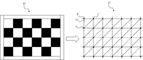
- the present invention generates a reference grid pattern corresponding to the reference check board pattern 10 shown in FIG. 2 (S10), and sets reference coordinate values for each intersection point of the grid pattern (S20).
- the reference image 20 in which the grid pattern image is divided into a plurality of reference polygons 30 is set.
- the plurality of reference polygons 30 are formed in a polygonal shape having vertices A ', B', and C '.
- a check board pattern is photographed by a plurality of wide-angle cameras, respectively, to obtain a distorted image 40 as shown in FIG. 3 (S40).
- the check board pattern of the distorted image 40 is recognized, and an edge of the check board pattern in the distorted image is detected as shown in FIG. 4 through morphology and robust operation (S50).
- a plurality of correction points are estimated and a correction order for the estimated correction points is selected (S60).
- the correction point estimation is estimated using the change in the brightness distribution in the vertical direction and the horizontal direction while performing line tracking along the detected edge region as shown in FIG. 5. That is, since the brightness variation is large at each intersection in the check board pattern, the point where the brightness variation is large during the line tracking process is estimated as a correction point and corrected according to the order estimated as the correction point as shown in FIG. 6. Select the order.
- the distortion points are divided into a plurality of distortion polygons having correction points A, B, and C (S70).
- each pixel coordinate of the distorted image is mapped to the reference coordinate so that the distorted polygon corresponds to the reference polygon according to the selected correction order, thereby obtaining each corrected image (S80). That is, each pixel in the distortion polygon 50 is mapped to the reference polygon 30 of the reference image. In this case, it is determined whether the pixel to be mapped is located inside the distortion polygon. If the pixel to be mapped is located inside the distortion polygon, the coordinates of the pixel are mapped to the reference coordinate. If the pixel to be mapped is not inside the distortion polygon, the mapping is performed. Exclude from the target.
- FIG. 8 is a view for explaining a process for determining whether a pixel to be mapped is located inside a distortion polygon according to the present invention.
- First as shown in FIG. Check if it is located within the distortion polygon consisting of B and C. To this end, it is necessary to obtain the coordinates of the points D and E of the square including vertices A, B, and C as shown in FIG.
- a part outside the coordinate may be defined as outside.
- the outside range condition is if (P x ⁇ D x ⁇ P x > E x ⁇ P y ⁇ D y ⁇ P y > E y ), and if the outside range condition is not satisfied, the corresponding pixel to be mapped (P You can see that is located inside the rectangle.
- the mapping target pixel P is located outside the distortion polygon.
- the condition for the pixel to be mapped (P) outside the distortion polygon is the outer range condition if (F x ⁇ D x ⁇ F x > E x ⁇ F y ⁇ D y ⁇ F y > E y ), Point F is a line segment This is a case where the mapping target pixel P is located in the OUT1 or OUT2 region.
- the outside range condition for the mapping target pixel P to be located outside the distortion polygon is if (P x ⁇ G x ⁇ P x > H x ⁇ P y ⁇ G y ⁇ P y > H y ).
- the case where the pixel P is located outside the rectangle BGFH corresponds to the case where the pixel to be mapped is located in the OUT3 region.
- the pixel to be mapped P is located inside the distortion polygon.
- mapping target pixel P is located inside the distortion polygon, the corresponding pixel is mapped to correspond to the reference image.
- FIG. 9 is a view for explaining a method of mapping a distorted polygon to a reference polygon according to the present invention.
- a first straight line passing through A) and the mapping target pixel P ) And the line segment facing the first reference vertex (A) The coordinate of the 1st intersection point (a) which () intersects is computed.
- one of the two except for the first reference vertex A is selected as the second reference vertex B, and a second straight line passing through the second reference vertex B and the mapping target pixel P ( ) And the line segment facing the second reference vertex (B)
- the coordinate of the 2nd intersection point (b) which () intersects is computed.
- the coordinates of the first intersection point a and the second intersection point b are obtained by the following equation.
- the coordinates of the points a and b are calculated by the following formula.
- mapping target pixel P is mapped in correspondence with the intersection point P'.
- the program recognizes the two line segments almost horizontally and an error occurs. Therefore, in order to correct such an error, the reference vertex should be selected such that the slope of two line segments passing through the mapping target pixel P faces the line segment sufficiently larger than the slope of each line segment of the polygon.
- FIG. 10 is a flowchart for explaining a process of selecting two reference vertices as reference points when mapping a polygon in an embodiment of the present invention
- FIG. 11 is a reference diagram for explaining the method of FIG. 10 and a point P in a triangle ABC.
- the distance between each vertex and P is compared, and the distance information between the vertex far from the point P and the point P is stored as dap (S200).
- the length of the dap and the dbp is compared to the point P and the longest vertex is determined by comparing the length of the dap and the dbp as shown in the following formula, and stored in the ABP. Determine the farthest vertex and store it in the ACP, compare the dbp and dcp lengths to determine the longest point as the farthest vertex and store the longest in the BCP.
- step S300 the slope between P and the vertex found in step S300 is calculated using the following formula (S400).
- the slope difference can be calculated. As the value approaches 0, the line segment passing through the pixel to be mapped P is closer to each line segment of the distortion polygon.
- FIG. 12 is a diagram illustrating an around view image that is finally combined in a method of generating a vehicle around view according to the present invention.
- Each of the correction images generated by the above-described method is combined with a planar image of a vehicle to generate an around view image. (S90).
Landscapes
- Engineering & Computer Science (AREA)
- Physics & Mathematics (AREA)
- General Physics & Mathematics (AREA)
- Theoretical Computer Science (AREA)
- Computer Vision & Pattern Recognition (AREA)
- Multimedia (AREA)
- Signal Processing (AREA)
- Image Processing (AREA)
- Closed-Circuit Television Systems (AREA)
Abstract
L'invention concerne un procédé de génération d'une image d'une vue autour d'un véhicule, qui consiste à estimer des coordonnées de polygone dans une image de distorsion obtenue par une caméra grand angle, et à cartographier en polygone les coordonnées de polygone estimées en une image standard. A cette fin, le procédé de génération d'une image d'une vue autour d'un véhicule consiste à corriger la distorsion radiale d'une image obtenue à partir de plusieurs caméras grand angle afin de générer une image de la vue, et comprend les étapes suivantes : définir une valeur de coordonnées standard par rapport à chaque point d'intersection d'un motif de grille standard et générer une image standard divisée par plusieurs polygones standards ayant des sommets standards (A', B', C') par rapport à une image de motif de grille ; capturer un motif en échiquier en utilisant plusieurs caméras grand angle afin d'obtenir chaque image de distorsion ; détecter le bord du motif d'échiquier dans chaque image de distorsion ; estimer plusieurs points de correction en utilisant des quantités de changement de répartition de luminosité dans une direction verticale et dans une direction parallèle pendant le suivi de ligne le long de la zone de bord détectée, et choisir un ordre de correction pour les points de correction estimés ; diviser chaque image de distorsion en plusieurs polygones de distorsion ayant des sommets de correction (A, B, C) ; cartographier chaque coordonnée de pixel de l'image de distorsion sur une coordonnée standard afin que le polygone de distorsion corresponde à un polygone standard en fonction de l'ordre de correction afin d'obtenir chaque image de correction ; et générer une image de la vue autour du véhicule en combinant chaque image de correction avec une image en plan du véhicule.
Applications Claiming Priority (2)
| Application Number | Priority Date | Filing Date | Title |
|---|---|---|---|
| KR1020110048380A KR101249791B1 (ko) | 2011-05-23 | 2011-05-23 | 차량 어라운드 뷰 영상 생성 방법 |
| KR10-2011-0048380 | 2011-05-23 |
Publications (3)
| Publication Number | Publication Date |
|---|---|
| WO2012161431A2 true WO2012161431A2 (fr) | 2012-11-29 |
| WO2012161431A3 WO2012161431A3 (fr) | 2013-01-17 |
| WO2012161431A9 WO2012161431A9 (fr) | 2013-03-28 |
Family
ID=47217840
Family Applications (1)
| Application Number | Title | Priority Date | Filing Date |
|---|---|---|---|
| PCT/KR2012/003482 Ceased WO2012161431A2 (fr) | 2011-05-23 | 2012-05-03 | Procédé de génération d'une image d'une vue autour d'un véhicule |
Country Status (2)
| Country | Link |
|---|---|
| KR (1) | KR101249791B1 (fr) |
| WO (1) | WO2012161431A2 (fr) |
Cited By (9)
| Publication number | Priority date | Publication date | Assignee | Title |
|---|---|---|---|---|
| CN103220548A (zh) * | 2013-04-23 | 2013-07-24 | 上海纵目科技有限公司 | 用于全景泊车标定的测试现场及其建设方法 |
| CN103761735A (zh) * | 2014-01-08 | 2014-04-30 | 惠州华阳通用电子有限公司 | 一种车载环视系统标定装置及方法 |
| CN110276716A (zh) * | 2019-06-19 | 2019-09-24 | 北京茵沃汽车科技有限公司 | 车辆前后视鱼眼图像的180度矫正视图的生成方法 |
| CN112734721A (zh) * | 2021-01-08 | 2021-04-30 | 昆山丘钛微电子科技股份有限公司 | 一种光轴偏转角度检测方法、装置、设备和介质 |
| CN113034616A (zh) * | 2021-03-31 | 2021-06-25 | 黑芝麻智能科技(上海)有限公司 | 车辆环视系统的相机外参标定方法、系统及环视系统 |
| CN115063739A (zh) * | 2022-06-10 | 2022-09-16 | 嘉洋智慧安全生产科技发展(北京)有限公司 | 异常行为的检测方法、装置、设备及计算机存储介质 |
| US11463669B2 (en) | 2019-01-02 | 2022-10-04 | Beijing Boe Optoelectronics Technology Co., Ltd. | Image processing method, image processing apparatus and display apparatus |
| CN118707720A (zh) * | 2024-08-28 | 2024-09-27 | 深圳市永泰光电有限公司 | 一种大景深超广角镜头的低形变控制方法 |
| CN119805360A (zh) * | 2025-03-17 | 2025-04-11 | 中国人民解放军海军大连舰艇学院 | 一种时差定位中计算目标位置的方法 |
Families Citing this family (14)
| Publication number | Priority date | Publication date | Assignee | Title |
|---|---|---|---|---|
| DE102014209137B4 (de) * | 2014-05-14 | 2023-02-02 | Volkswagen Aktiengesellschaft | Verfahren und Vorrichtung zur Kalibrierung eines Kamerasystems eines Kraftfahrzeugs |
| KR101592740B1 (ko) | 2014-07-24 | 2016-02-15 | 현대자동차주식회사 | 차량용 광각카메라의 영상 왜곡 보정 장치 및 방법 |
| KR102279026B1 (ko) * | 2014-11-07 | 2021-07-19 | 삼성전자주식회사 | 적어도 하나의 객체를 포함하는 영상에서 객체를 추출하여 보정한 영상을 제공하는 장치 및 방법 |
| KR101693820B1 (ko) * | 2016-01-13 | 2017-01-06 | 광운대학교 산학협력단 | Avm 영상 보정 장치 및 방법 |
| KR101694651B1 (ko) * | 2016-02-15 | 2017-01-09 | 이화여자대학교 산학협력단 | 3차원 위치 추정을 이용한 광각 렌즈 영상의 왜곡 보정 장치 및 그 방법 |
| CN107133911B (zh) * | 2016-02-26 | 2020-04-24 | 比亚迪股份有限公司 | 一种倒车影像显示方法及装置 |
| KR102441209B1 (ko) * | 2016-03-28 | 2022-09-07 | 한국자동차연구원 | Avm 시스템 어라운드 영상 정합성 평가방법 및 장치 |
| KR102477480B1 (ko) * | 2018-03-20 | 2022-12-14 | 주식회사 에이치엘클레무브 | 어라운드뷰 카메라의 캘리브레이션 장치 및 그 방법 |
| KR102053099B1 (ko) * | 2018-06-07 | 2019-12-06 | 현대오트론 주식회사 | 어라운드 뷰 모니터링 시스템 및 그것의 동작 방법 |
| KR102154798B1 (ko) * | 2019-01-14 | 2020-09-10 | 중앙대학교 산학협력단 | 주차면 만공차 감지 시스템 및 그 방법 |
| KR102167828B1 (ko) * | 2019-06-13 | 2020-10-20 | 주식회사 넥스트칩 | 왜곡 영상을 보정하는 방법 및 장치 |
| KR102124291B1 (ko) | 2020-02-12 | 2020-06-17 | 김정석 | 광학식 정밀측정기의 렌즈 측정오차 교정방법 |
| KR102836908B1 (ko) * | 2020-09-25 | 2025-07-21 | 현대모비스 주식회사 | 서라운드뷰 생성 시스템 및 방법 |
| KR20220061334A (ko) | 2020-11-05 | 2022-05-13 | 경기과학기술대학교 산학협력단 | 차량의 어라운드 뷰 제공 장치 |
Family Cites Families (4)
| Publication number | Priority date | Publication date | Assignee | Title |
|---|---|---|---|---|
| KR100808536B1 (ko) * | 2006-10-31 | 2008-03-06 | (주) 이즈커뮤니케이션즈 | 패턴 영상을 이용한 캘리브레이션 방법 |
| JP4906586B2 (ja) * | 2007-05-16 | 2012-03-28 | 三菱電機株式会社 | 歪み補正装置及びプログラム |
| JP2010257357A (ja) * | 2009-04-28 | 2010-11-11 | Renesas Electronics Corp | 画像処理装置、半導体データ処理装置及びデータ処理システム |
| JP2011101265A (ja) * | 2009-11-06 | 2011-05-19 | Nippon Seiki Co Ltd | 較正情報算出方法、較正情報算出装置、及び広角画像処理装置 |
-
2011
- 2011-05-23 KR KR1020110048380A patent/KR101249791B1/ko not_active Expired - Fee Related
-
2012
- 2012-05-03 WO PCT/KR2012/003482 patent/WO2012161431A2/fr not_active Ceased
Cited By (12)
| Publication number | Priority date | Publication date | Assignee | Title |
|---|---|---|---|---|
| CN103220548A (zh) * | 2013-04-23 | 2013-07-24 | 上海纵目科技有限公司 | 用于全景泊车标定的测试现场及其建设方法 |
| CN103761735A (zh) * | 2014-01-08 | 2014-04-30 | 惠州华阳通用电子有限公司 | 一种车载环视系统标定装置及方法 |
| US11463669B2 (en) | 2019-01-02 | 2022-10-04 | Beijing Boe Optoelectronics Technology Co., Ltd. | Image processing method, image processing apparatus and display apparatus |
| CN110276716A (zh) * | 2019-06-19 | 2019-09-24 | 北京茵沃汽车科技有限公司 | 车辆前后视鱼眼图像的180度矫正视图的生成方法 |
| CN110276716B (zh) * | 2019-06-19 | 2023-06-20 | 北京茵沃汽车科技有限公司 | 车辆前后视鱼眼图像的180度矫正视图的生成方法 |
| CN112734721A (zh) * | 2021-01-08 | 2021-04-30 | 昆山丘钛微电子科技股份有限公司 | 一种光轴偏转角度检测方法、装置、设备和介质 |
| CN112734721B (zh) * | 2021-01-08 | 2024-01-16 | 昆山丘钛微电子科技股份有限公司 | 一种光轴偏转角度检测方法、装置、设备和介质 |
| CN113034616A (zh) * | 2021-03-31 | 2021-06-25 | 黑芝麻智能科技(上海)有限公司 | 车辆环视系统的相机外参标定方法、系统及环视系统 |
| CN115063739A (zh) * | 2022-06-10 | 2022-09-16 | 嘉洋智慧安全生产科技发展(北京)有限公司 | 异常行为的检测方法、装置、设备及计算机存储介质 |
| CN115063739B (zh) * | 2022-06-10 | 2023-06-16 | 嘉洋智慧安全科技(北京)股份有限公司 | 异常行为的检测方法、装置、设备及计算机存储介质 |
| CN118707720A (zh) * | 2024-08-28 | 2024-09-27 | 深圳市永泰光电有限公司 | 一种大景深超广角镜头的低形变控制方法 |
| CN119805360A (zh) * | 2025-03-17 | 2025-04-11 | 中国人民解放军海军大连舰艇学院 | 一种时差定位中计算目标位置的方法 |
Also Published As
| Publication number | Publication date |
|---|---|
| WO2012161431A3 (fr) | 2013-01-17 |
| WO2012161431A9 (fr) | 2013-03-28 |
| KR20120130798A (ko) | 2012-12-04 |
| KR101249791B1 (ko) | 2013-04-03 |
Similar Documents
| Publication | Publication Date | Title |
|---|---|---|
| WO2012161431A2 (fr) | Procédé de génération d'une image d'une vue autour d'un véhicule | |
| JP6299124B2 (ja) | 投影システム、画像処理装置、投影方法およびプログラム | |
| WO2012176945A1 (fr) | Appareil destiné à synthétiser des images tridimensionnelles pour visualiser des environnements de véhicule et procédé associé | |
| TWI383666B (zh) | 多重鏡頭相機系統之先進式動態接圖方法 | |
| WO2021112462A1 (fr) | Procédé d'estimation de valeurs de coordonnées tridimensionnelles pour chaque pixel d'une image bidimensionnelle, et procédé d'estimation d'informations de conduite autonome l'utilisant | |
| WO2023273108A1 (fr) | Procédé et appareil de mesure de distance monoculaire, et appareil intelligent | |
| WO2016153100A1 (fr) | Appareil de traitement d'image comportant une fonction de compensation automatique pour une image obtenue à partir d'une caméra, et procédé associé | |
| JP2003254748A (ja) | ステレオ画像特性検査システム | |
| JP2008187564A (ja) | カメラ校正装置及び方法並びに車両 | |
| WO2011074721A1 (fr) | Dispositif de traitement d'image et procédé de mise en correspondance d'images obtenues à partir d'une pluralité de caméras grand angle | |
| WO2020246710A1 (fr) | Procédé de détermination de carte de profondeur et dispositif électronique auquel le même procédé est appliqué | |
| WO2013125768A1 (fr) | Appareil et procédé pour détecter automatiquement un objet et des informations de profondeur d'image photographiée par un dispositif de capture d'image ayant une ouverture de filtre à couleurs multiples | |
| WO2021221334A1 (fr) | Dispositif de génération de palette de couleurs formée sur la base d'informations gps et de signal lidar, et son procédé de commande | |
| CN111311682A (zh) | 一种led屏校正过程中的位姿估计方法、装置及电子设备 | |
| JP2940736B2 (ja) | 画像処理装置及びこの画像処理装置における歪み補正方法 | |
| CN113034616A (zh) | 车辆环视系统的相机外参标定方法、系统及环视系统 | |
| WO2012148025A1 (fr) | Dispositif et procédé servant à détecter un objet tridimensionnel au moyen d'une pluralité de caméras | |
| WO2020235734A1 (fr) | Procédé destiné à estimer la distance à un véhicule autonome et sa position au moyen d'une caméra monoscopique | |
| CN106204416B (zh) | 全景泊车辅助系统及其广角图像调试方法和装置 | |
| WO2015056826A1 (fr) | Appareil et procédé de traitement des images d'un appareil de prise de vues | |
| WO2016204068A1 (fr) | Appareil de traitement d'image, procédé de traitement d'image et système de projection | |
| JP6956051B2 (ja) | 画像処理装置、運転支援システム、画像処理方法及びプログラム | |
| JP2003065714A (ja) | カメラ・キャリブレーションのためのガイド装置及びガイド方法、並びに、カメラ・キャリブレーション装置 | |
| WO2016035924A1 (fr) | Procédé et système de détection de déplacement | |
| JP5240517B2 (ja) | 車載カメラの校正装置 |
Legal Events
| Date | Code | Title | Description |
|---|---|---|---|
| 121 | Ep: the epo has been informed by wipo that ep was designated in this application |
Ref document number: 12789295 Country of ref document: EP Kind code of ref document: A2 |
|
| NENP | Non-entry into the national phase |
Ref country code: DE |
|
| 122 | Ep: pct application non-entry in european phase |
Ref document number: 12789295 Country of ref document: EP Kind code of ref document: A2 |