WO2012164600A1 - 給湯システム - Google Patents
給湯システム Download PDFInfo
- Publication number
- WO2012164600A1 WO2012164600A1 PCT/JP2011/002975 JP2011002975W WO2012164600A1 WO 2012164600 A1 WO2012164600 A1 WO 2012164600A1 JP 2011002975 W JP2011002975 W JP 2011002975W WO 2012164600 A1 WO2012164600 A1 WO 2012164600A1
- Authority
- WO
- WIPO (PCT)
- Prior art keywords
- hot water
- water supply
- temperature
- control board
- water storage
- Prior art date
- Legal status (The legal status is an assumption and is not a legal conclusion. Google has not performed a legal analysis and makes no representation as to the accuracy of the status listed.)
- Ceased
Links
Images

Classifications
-
- F—MECHANICAL ENGINEERING; LIGHTING; HEATING; WEAPONS; BLASTING
- F24—HEATING; RANGES; VENTILATING
- F24D—DOMESTIC- OR SPACE-HEATING SYSTEMS, e.g. CENTRAL HEATING SYSTEMS; DOMESTIC HOT-WATER SUPPLY SYSTEMS; ELEMENTS OR COMPONENTS THEREFOR
- F24D19/00—Details
- F24D19/10—Arrangement or mounting of control or safety devices
- F24D19/1006—Arrangement or mounting of control or safety devices for water heating systems
-
- F—MECHANICAL ENGINEERING; LIGHTING; HEATING; WEAPONS; BLASTING
- F24—HEATING; RANGES; VENTILATING
- F24D—DOMESTIC- OR SPACE-HEATING SYSTEMS, e.g. CENTRAL HEATING SYSTEMS; DOMESTIC HOT-WATER SUPPLY SYSTEMS; ELEMENTS OR COMPONENTS THEREFOR
- F24D17/00—Domestic hot-water supply systems
- F24D17/0036—Domestic hot-water supply systems with combination of different kinds of heating means
-
- F—MECHANICAL ENGINEERING; LIGHTING; HEATING; WEAPONS; BLASTING
- F24—HEATING; RANGES; VENTILATING
- F24D—DOMESTIC- OR SPACE-HEATING SYSTEMS, e.g. CENTRAL HEATING SYSTEMS; DOMESTIC HOT-WATER SUPPLY SYSTEMS; ELEMENTS OR COMPONENTS THEREFOR
- F24D17/00—Domestic hot-water supply systems
- F24D17/02—Domestic hot-water supply systems using heat pumps
-
- F—MECHANICAL ENGINEERING; LIGHTING; HEATING; WEAPONS; BLASTING
- F24—HEATING; RANGES; VENTILATING
- F24D—DOMESTIC- OR SPACE-HEATING SYSTEMS, e.g. CENTRAL HEATING SYSTEMS; DOMESTIC HOT-WATER SUPPLY SYSTEMS; ELEMENTS OR COMPONENTS THEREFOR
- F24D19/00—Details
- F24D19/10—Arrangement or mounting of control or safety devices
- F24D19/1006—Arrangement or mounting of control or safety devices for water heating systems
- F24D19/1051—Arrangement or mounting of control or safety devices for water heating systems for domestic hot water
-
- F—MECHANICAL ENGINEERING; LIGHTING; HEATING; WEAPONS; BLASTING
- F24—HEATING; RANGES; VENTILATING
- F24H—FLUID HEATERS, e.g. WATER OR AIR HEATERS, HAVING HEAT-GENERATING MEANS, e.g. HEAT PUMPS, IN GENERAL
- F24H4/00—Fluid heaters characterised by the use of heat pumps
- F24H4/02—Water heaters
- F24H4/04—Storage heaters
-
- F—MECHANICAL ENGINEERING; LIGHTING; HEATING; WEAPONS; BLASTING
- F24—HEATING; RANGES; VENTILATING
- F24H—FLUID HEATERS, e.g. WATER OR AIR HEATERS, HAVING HEAT-GENERATING MEANS, e.g. HEAT PUMPS, IN GENERAL
- F24H9/00—Details
- F24H9/20—Arrangement or mounting of control or safety devices
- F24H9/2007—Arrangement or mounting of control or safety devices for water heaters
- F24H9/2014—Arrangement or mounting of control or safety devices for water heaters using electrical energy supply
- F24H9/2021—Storage heaters
-
- F—MECHANICAL ENGINEERING; LIGHTING; HEATING; WEAPONS; BLASTING
- F24—HEATING; RANGES; VENTILATING
- F24D—DOMESTIC- OR SPACE-HEATING SYSTEMS, e.g. CENTRAL HEATING SYSTEMS; DOMESTIC HOT-WATER SUPPLY SYSTEMS; ELEMENTS OR COMPONENTS THEREFOR
- F24D2220/00—Components of central heating installations excluding heat sources
- F24D2220/04—Sensors
- F24D2220/042—Temperature sensors
-
- F—MECHANICAL ENGINEERING; LIGHTING; HEATING; WEAPONS; BLASTING
- F24—HEATING; RANGES; VENTILATING
- F24D—DOMESTIC- OR SPACE-HEATING SYSTEMS, e.g. CENTRAL HEATING SYSTEMS; DOMESTIC HOT-WATER SUPPLY SYSTEMS; ELEMENTS OR COMPONENTS THEREFOR
- F24D2240/00—Characterizing positions, e.g. of sensors, inlets, outlets
- F24D2240/26—Vertically distributed at fixed positions, e.g. multiple sensors distributed over the height of a tank, or a vertical inlet distribution pipe having a plurality of orifices
-
- Y—GENERAL TAGGING OF NEW TECHNOLOGICAL DEVELOPMENTS; GENERAL TAGGING OF CROSS-SECTIONAL TECHNOLOGIES SPANNING OVER SEVERAL SECTIONS OF THE IPC; TECHNICAL SUBJECTS COVERED BY FORMER USPC CROSS-REFERENCE ART COLLECTIONS [XRACs] AND DIGESTS
- Y02—TECHNOLOGIES OR APPLICATIONS FOR MITIGATION OR ADAPTATION AGAINST CLIMATE CHANGE
- Y02B—CLIMATE CHANGE MITIGATION TECHNOLOGIES RELATED TO BUILDINGS, e.g. HOUSING, HOUSE APPLIANCES OR RELATED END-USER APPLICATIONS
- Y02B10/00—Integration of renewable energy sources in buildings
- Y02B10/20—Solar thermal
-
- Y—GENERAL TAGGING OF NEW TECHNOLOGICAL DEVELOPMENTS; GENERAL TAGGING OF CROSS-SECTIONAL TECHNOLOGIES SPANNING OVER SEVERAL SECTIONS OF THE IPC; TECHNICAL SUBJECTS COVERED BY FORMER USPC CROSS-REFERENCE ART COLLECTIONS [XRACs] AND DIGESTS
- Y02—TECHNOLOGIES OR APPLICATIONS FOR MITIGATION OR ADAPTATION AGAINST CLIMATE CHANGE
- Y02B—CLIMATE CHANGE MITIGATION TECHNOLOGIES RELATED TO BUILDINGS, e.g. HOUSING, HOUSE APPLIANCES OR RELATED END-USER APPLICATIONS
- Y02B10/00—Integration of renewable energy sources in buildings
- Y02B10/70—Hybrid systems, e.g. uninterruptible or back-up power supplies integrating renewable energies
Definitions
- the present invention relates to a hot water supply system configured to heat water and store it in a hot water storage tank so that the hot water can be supplied from the hot water storage tank to a hot water supply load.
- a temperature sensor such as a thermistor for measuring the internal water temperature (six in the example) is provided, and the amount of hot water stored is determined by comparing each temperature sensor with the set temperature (for example, Patent Document 1). reference).
- a hot water storage tank is divided into a plurality of parts, and a temperature sensor is provided in each hot water storage tank.
- operation control of the hot water supply apparatus is performed by a control means provided separately from the hot water supply apparatus.
- Outputs from temperature sensors (six in this example) provided in each hot water storage tank are input to the control means via a substrate included in the hot water supply apparatus. Therefore, since there are six temperature sensors, a substrate (seven or more inputs / outputs) capable of receiving six inputs and outputting outputs (one or more) to the control means is required. For this reason, the dimension of a board
- the manufacturing cost increases, the control box of the hot water supply apparatus increases, and in some cases, the dimensions of the hot water supply apparatus itself may increase. Further, in addition to the wiring through which the temperature sensor in each hot water storage tank is routed to the hot water supply device, a work for wiring from the hot water supply device to the control means is also required.
- the present invention is to obtain a hot water supply system capable of detecting the amount of hot water storage by accurately detecting the temperature in the hot water storage tank while reducing the size of the substrate.
- a hot water supply system includes a hot water storage tank for storing hot water, a plurality of temperature sensors that are attached in the height direction of the hot water storage tank and that detect temperatures at the respective positions, and a plurality of hot water for heating the hot water storage tank. And a control board having an input port for inputting a signal from a temperature sensor and a control means for controlling each hot water supply apparatus, and signals sent from a plurality of temperature sensors are distributed to a plurality of control boards. The control boards are connected for communication.
- the signals from the temperature sensors are distributed and inputted to the plurality of control boards, and the control boards are connected so that they can communicate with each other.
- the number of ports can be reduced.
- each control board can be comprised with a compact board
- 4 to 6 temperature sensors are attached to a hot water storage tank, for example, but if there are two control boards, the number of input ports is comprised of, for example, three control boards so that two to three signals can be input. can do.
- FIG. 1 is a diagram showing a configuration of a hot water supply system having a hot water supply apparatus and a hot water storage tank according to Embodiment 1 of the present invention.
- processing related to hot water supply such as heating of water is performed by two hot water supply apparatuses.
- one of the two hot water supply apparatuses is the master unit side hot water supply apparatus 1 and the other is the slave unit side hot water supply apparatus 4, and the master unit side hot water supply apparatus 1 mainly performs operations related to hot water supply. .
- the master unit-side hot water supply device 1 and the slave unit-side hot water supply device 4 of the present embodiment circulate refrigerant by connecting a compressor, a condenser, a throttling device, and an evaporator.
- a heat pump circuit (refrigerant circuit) is configured. Then, the refrigerant dissipates heat in the condenser and heats the water by heat exchange.
- the base unit side hot water supply apparatus 1 includes a base unit side control board 3 in a base unit side control box 2. Moreover, the subunit
- the base unit side control board 3 is a board having control means such as a computer for controlling each device constituting the base unit side hot water supply apparatus 1.
- mobile_unit side control board 6 is a board
- the master-side control board 3 uses, as data, the temperature related to the detection of temperature sensors 8a to 8f such as thermistors provided in the hot water storage tank 7 for control. Connection of the parent device side control board 3, the child device side control board 6, and the temperature sensors 8a to 8f will be described later.
- the hot water storage tank 7 is a tank for storing hot water related to the heating of the parent device side hot water supply device 1 and the child device side hot water supply device 4.
- a water supply pipe (not shown), a hot water supply pipe (not shown), etc. are connected to the hot water storage tank 7, water is supplied from the lower part of the hot water storage tank 7 through the water supply pipe, and hot water is discharged to the hot water supply load through the hot water supply pipe.
- the hot water storage tank 7 of the present embodiment is a sealed type.
- temperature sensors 8a, 8b, 8c, 8d, 8e and 8f are arranged in the sealed hot water storage tank 7 from the upper part to the lower part (in the height direction) of the hot water storage tank 7, respectively.
- the temperature sensors 8a to 8f are temperature detection means for detecting the amount of hot water stored in the hot water storage tank 7, and the like. For example, if it is determined that there is a temperature difference of a predetermined value or more between the temperature sensor 8b and the temperature sensor 8c, it can be determined that there is a water surface at a position between the temperature sensor 8b and the temperature sensor 8c.
- the electrical resistances of the temperature sensors 8a to 8f change depending on the temperature, and output as a DC signal of 4 to 20 mA, for example, depending on the temperature related to detection.
- the master-side hot water supply apparatus 1 since the master-side hot water supply apparatus 1 mainly performs control based on the temperature of hot water in the hot water storage tank 7 or the like, a temperature sensor at a position necessary for performing control is used. A signal related to temperature 8 is preferentially input to the base unit side control board 3. Basically, the uppermost and lowermost positions are required. In addition, 2 to 3 is appropriate as the number of signals that are connected to one substrate and input a signal. Therefore, in the present embodiment, the connection lines 9a, 9b, and 9c are used to input a signal related to the temperature detected by the temperature sensors 8a, 8b, and 8f to the base unit side control board 3 of the base unit side hot water supply apparatus 1. Connect with.
- connection line of 10a, 10b, 10c in order to make the signal concerning the temperature which the temperature sensors 8c, 8d and 8e in the hot water storage tank 7 detect input into the subunit
- a transmission line 11 for communicating with the slave unit side control board 6 is connected.
- hot water supply systems used for business purposes in welfare facilities, hospitals, hotels, dormitories, training centers, golf courses, and the like.
- HP heating capacity of about 40 kW
- the ratio of the hot water supply system constituted by a plurality of hot water supply apparatuses is about 70% of the total commercial hot water supply system.
- the hot water supply system of the present embodiment has a high ratio of configuring a system using a plurality of hot water supply apparatuses. Therefore, for one hot water supply apparatus (considering risk dispersion), for example, It is a control board that can input signals from three temperature sensors in the hot water storage tank via a connection line. Then, the signals are inputted to a plurality of hot water supply devices (considering risk dispersion), and further, communication can be performed by connecting the control boards of each hot water supply device with a transmission line. Is.
- a signal related to the temperature of the temperature sensor 8 at a position required for performing control is preferentially input to the parent-side control board 3, so that communication between the control boards is not possible.
- the amount of stored hot water or the like can be determined only by a signal input to the base unit side control board 3.
- the operation will be described. Inside the enclosed hot water storage tank 7, the water temperature from the water supply pipe (not shown) at the bottom of the hot water storage tank 7 is raised at once to raise the temperature to the set temperature, and the hot water supply pipe at the upper part of the hot water storage tank 7. Hot water is supplied from (not shown) to a hot water supply load (not shown) such as a bath. At this time, water is supplied into the hot water storage tank 7 by the amount used for hot water supply. For this reason, about the water in the hot water storage tank 7, a high temperature part and a low temperature part are made, and temperature stratification is formed.
- water is supplied from a lower part of the hot water storage tank 7 to a water supply inlet (not shown) of the master unit side hot water supply device 1 and the slave unit side hot water supply device 4, and the water supply outlet of the master unit side hot water supply device 1 and the slave unit side hot water supply device 4 Hot water heated from the section (not shown) is stored in the upper part (not shown) of the hot water storage tank 7.
- the temperature gradient of the hot water stored in the hot water storage tank 7 is generated from the upper part to the lower part, the temperature is lower in the lower part than in the upper part, and temperature stratification is formed.
- the temperature sensors 8a, 8b, 8c, 8d, 8e and 8f are provided from the upper part to the lower part in the height direction in the hot water storage tank 7, the temperature and the set temperature related to the detection of the temperature sensors 8a to 8f.
- the amount of hot water stored (for example, the amount of hot water maintained at the set temperature) is determined based on a comparison with (for example, 55 ° C.).
- the ratio of the hot water storage amount (remaining hot water) corresponding to the installation position of the temperature sensor 8a (
- the hot water storage amount is 10% (V8a).
- the hot water storage amount (remaining hot water) corresponding to the installation position of the temperature sensor 8b is 30% (V8b).
- the ratio of the amount of hot water stored (remaining hot water) corresponding to the installation position of the temperature sensor 8c is 50% (V8c)
- the amount of hot water storage (remaining hot water) corresponding to the installation position of the temperature sensor 8d is 60% (V8d).
- the amount of hot water stored (remaining hot water) corresponding to the installation position of the temperature sensor 8e is 80% (V8e).
- the temperature detected by the temperature sensor 8a is T8a, and the temperature detected by the temperature sensor 8b is T8b.
- the temperature detected by the temperature sensor 8c is T8c, and the temperature detected by the temperature sensor 8d is T8d.
- the temperature detected by the temperature sensor 8e is T8e, and the temperature detected by the temperature sensor 8f is T8f.
- the hot water storage amount (remaining hot water) of the hot water storage tank 7 and the average hot water storage temperature performed by the master-side control board 3 will be described.
- the temperatures related to detection by each of the temperature sensors 8a to 8f one having a set temperature Te (for example, 55 ° C.) or higher is selected.
- the temperature which concerns on the detection of the temperature sensor 8 in the lowest position is selected as a representative temperature. For example, if the temperature T8a, the temperature T8b, the temperature T8c, and the temperature T8d are equal to or higher than the set temperature 55 ° C., the temperature T8d is selected as the representative temperature.
- the representative temperature is T8 n and the amount of hot water stored in the temperature sensor 8 related to detection of the representative temperature T8 n is V8 n . Further, the temperature related to the detection of the temperature sensor 8 installed at a position one step lower than the temperature sensor 8 related to the detection of the representative temperature T8 n is T8 n + 1, and the hot water storage amount corresponding to the installation position is V8 n + 1. Then, the amount of stored hot water is expressed by the following equation (1).
- the hot water storage amount V8d corresponding to T8d is 60%.
- T8 n + 1 is expressed by the equation (2) because when T8e is 30 ° C., the hot water storage amount V8e corresponding to T8e is 80%.
- the average hot water storage temperature is expressed by equation (3).
- the base unit side control board 3 controls the operation based on whether or not the current hot water storage amount has reached the target hot water storage amount.
- the target hot water storage amount is 50% during the day, the target hot water storage amount is 100% at night, and 10% is used to prevent drought, and the target hot water storage amount is determined according to the conditions, and the operation is controlled.
- the signals from the temperature sensors 8a to 8f are distributed to the master unit side control board 3 and the slave unit side control board 6 respectively to connect the communication lines 9a to 9c. Since signals are input through the communication lines 10a to 10c, and the base unit side control board 3 and the handset side control board 6 are connected by the transmission line 11, communication is possible. The number of ports can be reduced. For this reason, each control board can be comprised with a compact board
- the uppermost part is used as the temperature sensor 8 that sends a temperature signal to the base unit side control board 3.
- the temperature sensor 8a at the bottom, the temperature sensor 8b at the bottom, and the like are input, and the signal related to the temperature at the position necessary for performing control is input to the parent control board 3 preferentially. For example, if the target hot water storage amount of 100% at night and 10% of drought prevention can be determined, necessary control such as ensuring the hot water storage amount and preventing problems due to drought can be performed. It can be carried out.
- the hot water supply operation can be controlled without providing any control means other than the hot water supply apparatus, the installation work can be simplified and the cost can be reduced.
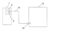
- FIG. FIG. 2 is a diagram showing a configuration of a hot water supply system having a hot water supply apparatus and a hot water storage tank in Embodiment 2 of the present invention.
- a hot water storage tank 12 is an open type hot water storage tank.
- a hot water supply system may be configured by combining an open hot water storage tank 12 communicating with the atmosphere and a hot water supply device.
- the amount of hot water stored in the open-type hot water storage tank 12 is measured by a water level sensor (pressure sensor) 13.
- the water level sensor 13 also outputs a DC signal of 4 to 20 mA based on the pressure (water pressure) detected between 0 and 50 kPa.
- the temperature sensor 8 and the port in the embodiment can be used.
- the water level sensor 13 and the base unit side control board 3 of the base unit side hot water supply device 1 are connected by the connection line 14, the temperature sensor of the sealed hot water storage tank 7 even when connected to the open type hot water storage tank 12.
- the same port it is possible to handle the hot water storage tank with the same base unit side control board 3 regardless of the sealed type or the open type.
- 1 parent device side hot water supply device 2 parent device side control box, 3 parent device side control board, 4 slave device side hot water supply device, 5 slave device side control box, 6 slave device side control board, 7, 12 hot water storage tank, 8a ⁇ 8f Temperature sensor, 9a-9c, 10a-10c, 14 communication line, 11 transmission line, 13 water level sensor.
Landscapes
- Engineering & Computer Science (AREA)
- Physics & Mathematics (AREA)
- Thermal Sciences (AREA)
- Chemical & Material Sciences (AREA)
- Combustion & Propulsion (AREA)
- Mechanical Engineering (AREA)
- General Engineering & Computer Science (AREA)
- Heat-Pump Type And Storage Water Heaters (AREA)
Abstract
Description
図1はこの発明の実施の形態1における給湯装置と貯湯タンクとを有する給湯システムの構成を示す図である。実施の形態1における給湯システムにおいては、図1に示すように、2台の給湯装置で、水の加熱等、給湯に係る処理を行う。2台の給湯装置について、本実施の形態では、一方を親機側給湯装置1とし、他方を子機側給湯装置4とし、親機側給湯装置1が主として給湯に係る運転を行うものとする。ここで、特に限定するものではないが、本実施の形態の親機側給湯装置1及び子機側給湯装置4は、圧縮機、凝縮器、絞り装置及び蒸発器を配管接続して冷媒を循環させるヒートポンプ回路(冷媒回路)を構成する。そして、凝縮器において冷媒を放熱させて熱交換により水を加熱する。
現在の貯湯量=V8n +(T8n -Te)×(V8n+1 -V8n )
/(T8n -T8n+1 ) …(1)
現在の貯湯量=V8d+(T8d-55)×(V8e-V8d)/(T8d-T8e)
=60%+(60℃-55℃)×(80%-60%)/(60℃-30℃)
=約63% …(2)
平均貯湯温度=(T8a+T8b+T8c+T8d)/4 …(3)
図2はこの発明の実施の形態2における給湯装置と貯湯タンクとを有する給湯システムの構成を示す図である。図2において、貯湯タンク12は開放型の貯湯タンクである。
Claims (4)
- 湯を貯めるための貯湯タンクと、
前記貯湯タンクの高さ方向に取り付けられ、それぞれ取り付けられた位置における温度を検出する複数の温度センサと
前記貯湯タンクの湯水を加熱する複数の給湯装置と、
各給湯装置を制御する制御手段を搭載する制御基板とを備え、
前記複数の温度センサが送る信号を、複数の制御基板に分散して入力させ、
各制御基板間を通信接続することを特徴とする給湯システム。 - 最上部の位置に取り付けられた前記温度センサ及び最下部の位置に取り付けられた前記温度センサからの信号が、同じ制御基板に入力されるようにすることを特徴とする請求項1に記載の給湯システム。
- 1つの制御基板の前記温度センサからの信号の入力ポート数を3つとし、信号入力数を2つ又は3つとすることを特徴とする請求項1又は2に記載の給湯システム。
- 前記制御基板が有する、前記温度センサからの信号の入力ポートが、貯湯タンクに取り付けられる水位センサからの信号を入力可能であることを特徴とする請求項1~3のいずれかに記載の給湯システム。
Priority Applications (5)
| Application Number | Priority Date | Filing Date | Title |
|---|---|---|---|
| CN201180071036.3A CN103547870B (zh) | 2011-05-27 | 2011-05-27 | 热水供应系统 |
| PCT/JP2011/002975 WO2012164600A1 (ja) | 2011-05-27 | 2011-05-27 | 給湯システム |
| EP11866897.9A EP2716992B1 (en) | 2011-05-27 | 2011-05-27 | Hot water supply system |
| JP2013517682A JP5745624B2 (ja) | 2011-05-27 | 2011-05-27 | 給湯システム |
| US14/110,981 US9671116B2 (en) | 2011-05-27 | 2011-05-27 | Hot water supply system |
Applications Claiming Priority (1)
| Application Number | Priority Date | Filing Date | Title |
|---|---|---|---|
| PCT/JP2011/002975 WO2012164600A1 (ja) | 2011-05-27 | 2011-05-27 | 給湯システム |
Publications (1)
| Publication Number | Publication Date |
|---|---|
| WO2012164600A1 true WO2012164600A1 (ja) | 2012-12-06 |
Family
ID=47258497
Family Applications (1)
| Application Number | Title | Priority Date | Filing Date |
|---|---|---|---|
| PCT/JP2011/002975 Ceased WO2012164600A1 (ja) | 2011-05-27 | 2011-05-27 | 給湯システム |
Country Status (5)
| Country | Link |
|---|---|
| US (1) | US9671116B2 (ja) |
| EP (1) | EP2716992B1 (ja) |
| JP (1) | JP5745624B2 (ja) |
| CN (1) | CN103547870B (ja) |
| WO (1) | WO2012164600A1 (ja) |
Cited By (1)
| Publication number | Priority date | Publication date | Assignee | Title |
|---|---|---|---|---|
| EP3078942A1 (en) | 2015-04-10 | 2016-10-12 | Carrier Corporation | Methods for determining a volume of liquid at a predetermined temperature, for calculating quantities of thermal energy, and for determining a profile of hot water consumption |
Families Citing this family (4)
| Publication number | Priority date | Publication date | Assignee | Title |
|---|---|---|---|---|
| WO2016149786A1 (en) * | 2015-03-25 | 2016-09-29 | Dominique Boivin | Water heating assembly for providing hot water in a reduced time to a point of use, and related kit, use and method |
| CN106440553B (zh) * | 2016-09-12 | 2019-01-04 | 珠海格力电器股份有限公司 | 多联机空调自动设置主子机的方法及装置 |
| US11287144B2 (en) | 2019-07-31 | 2022-03-29 | Rheem Manufacturing Company | Water heaters with real-time hot water supply determination |
| FR3102836B1 (fr) * | 2019-10-30 | 2022-06-17 | Atlantic Industrie Sas | Dispositif de chauffage d’eau |
Citations (3)
| Publication number | Priority date | Publication date | Assignee | Title |
|---|---|---|---|---|
| JPS6136256U (ja) * | 1984-07-31 | 1986-03-06 | ダイキン工業株式会社 | 給湯機 |
| JP2005134062A (ja) * | 2003-10-31 | 2005-05-26 | Daikin Ind Ltd | ヒートポンプ式給湯装置及び分岐ユニット |
| JP4139826B2 (ja) | 2005-06-13 | 2008-08-27 | 株式会社日本サーモエナー | ハイブリッド給湯システム |
Family Cites Families (13)
| Publication number | Priority date | Publication date | Assignee | Title |
|---|---|---|---|---|
| US2157910A (en) * | 1937-11-26 | 1939-05-09 | Edison General Elec Appliance | Liquid heater |
| DE2637482A1 (de) * | 1976-08-20 | 1978-02-23 | Thyssen Industrie | Stehender, isolierter doppelmantelwaermetauscher |
| US4333002A (en) * | 1980-09-02 | 1982-06-01 | A. O. Smith Corporation | Multiple device control apparatus |
| US4672529A (en) * | 1984-10-26 | 1987-06-09 | Autech Partners Ltd. | Self contained data acquisition apparatus and system |
| CA2151881A1 (en) * | 1995-06-15 | 1996-12-16 | Nazir Dosani | Programmable thermostat to reduce bacterial proliferation to prevent legionellosis |
| EP1157324A4 (en) | 1998-12-18 | 2009-06-17 | Triconex Corp | PROCESS AND DEVICE FOR PROCESSING CONTROL USING A MULTIPLE REDUNDANT PROCESS CONTROL SYSTEM |
| JP5011713B2 (ja) * | 2005-11-22 | 2012-08-29 | 株式会社デンソー | ヒートポンプ式給湯装置 |
| US8983283B2 (en) * | 2006-01-27 | 2015-03-17 | Emerson Electric Co. | Method and apparatus for operating an electric water heater using adjustable temperature setpoints |
| US8733429B2 (en) * | 2006-02-13 | 2014-05-27 | The H.L. Turner Group, Inc. | Hybrid heating and/or cooling system |
| US7668998B2 (en) * | 2008-01-08 | 2010-02-23 | Parata Systems, Llc | Methods, systems, and devices for providing an interrupt scheme in automated pharmaceutical dispensing machines without centralized arbitration |
| JP4424554B2 (ja) * | 2008-03-04 | 2010-03-03 | リンナイ株式会社 | 貯湯式給湯装置 |
| JP2010002078A (ja) * | 2008-06-18 | 2010-01-07 | Denso Corp | 給湯装置、給湯装置の制御装置及び複数の電動素子を有する装置の制御装置 |
| US8498523B2 (en) * | 2009-02-03 | 2013-07-30 | Intellihot, Inc. | Apparatus and control method for a hybrid tankless water heater |
-
2011
- 2011-05-27 US US14/110,981 patent/US9671116B2/en active Active
- 2011-05-27 EP EP11866897.9A patent/EP2716992B1/en active Active
- 2011-05-27 WO PCT/JP2011/002975 patent/WO2012164600A1/ja not_active Ceased
- 2011-05-27 CN CN201180071036.3A patent/CN103547870B/zh active Active
- 2011-05-27 JP JP2013517682A patent/JP5745624B2/ja active Active
Patent Citations (3)
| Publication number | Priority date | Publication date | Assignee | Title |
|---|---|---|---|---|
| JPS6136256U (ja) * | 1984-07-31 | 1986-03-06 | ダイキン工業株式会社 | 給湯機 |
| JP2005134062A (ja) * | 2003-10-31 | 2005-05-26 | Daikin Ind Ltd | ヒートポンプ式給湯装置及び分岐ユニット |
| JP4139826B2 (ja) | 2005-06-13 | 2008-08-27 | 株式会社日本サーモエナー | ハイブリッド給湯システム |
Non-Patent Citations (1)
| Title |
|---|
| See also references of EP2716992A4 |
Cited By (1)
| Publication number | Priority date | Publication date | Assignee | Title |
|---|---|---|---|---|
| EP3078942A1 (en) | 2015-04-10 | 2016-10-12 | Carrier Corporation | Methods for determining a volume of liquid at a predetermined temperature, for calculating quantities of thermal energy, and for determining a profile of hot water consumption |
Also Published As
| Publication number | Publication date |
|---|---|
| EP2716992B1 (en) | 2016-10-05 |
| US20140027524A1 (en) | 2014-01-30 |
| JP5745624B2 (ja) | 2015-07-08 |
| EP2716992A1 (en) | 2014-04-09 |
| EP2716992A4 (en) | 2014-12-17 |
| JPWO2012164600A1 (ja) | 2014-07-31 |
| CN103547870A (zh) | 2014-01-29 |
| US9671116B2 (en) | 2017-06-06 |
| CN103547870B (zh) | 2017-03-22 |
Similar Documents
| Publication | Publication Date | Title |
|---|---|---|
| JP5745624B2 (ja) | 給湯システム | |
| CN103953964B (zh) | 燃气采暖热水炉并联供热系统 | |
| US12117203B2 (en) | Hybrid water heater with adaptive temperature control | |
| JP5076061B2 (ja) | 給湯システム | |
| JP6323358B2 (ja) | 貯湯式電気給湯機 | |
| EP3654131B1 (en) | Temperature control system | |
| KR20150141455A (ko) | 히트펌프 시스템용 펌프 통합 유닛 | |
| JP2006234248A (ja) | ヒートポンプ式給湯装置 | |
| JP5656166B2 (ja) | 即湯システム | |
| JP2009097770A (ja) | ヒートポンプ式温水暖房装置の循環流量算出方法 | |
| JPWO2018087888A1 (ja) | 給湯システム、温度分離装置、及びタンク | |
| JP5809853B2 (ja) | 集合住宅用給湯設備 | |
| JP5924170B2 (ja) | ヒートポンプシステム | |
| WO2020100317A1 (ja) | 空調システム | |
| JP6090907B2 (ja) | 給湯システム | |
| JP6672950B2 (ja) | 給湯システム | |
| JP6618748B2 (ja) | 給湯システムの運転方法及び給湯システムの再構築方法 | |
| JP2006250367A (ja) | ヒートポンプ給湯機 | |
| JP2013181667A (ja) | 貯湯式給湯装置 | |
| JP2014052154A (ja) | 給湯装置 | |
| JP7342643B2 (ja) | 貯湯式給湯装置 | |
| JP2011208930A (ja) | 給湯システム | |
| JP2013108650A (ja) | 温水床暖房装置および温水床暖房装置の配管接続判定方法 | |
| JP5474906B2 (ja) | ヒートポンプ式給湯装置 | |
| JP4827527B2 (ja) | ヒートポンプ給湯機 |
Legal Events
| Date | Code | Title | Description |
|---|---|---|---|
| 121 | Ep: the epo has been informed by wipo that ep was designated in this application |
Ref document number: 11866897 Country of ref document: EP Kind code of ref document: A1 |
|
| WWE | Wipo information: entry into national phase |
Ref document number: 14110981 Country of ref document: US |
|
| REEP | Request for entry into the european phase |
Ref document number: 2011866897 Country of ref document: EP |
|
| WWE | Wipo information: entry into national phase |
Ref document number: 2011866897 Country of ref document: EP |
|
| ENP | Entry into the national phase |
Ref document number: 2013517682 Country of ref document: JP Kind code of ref document: A |
|
| NENP | Non-entry into the national phase |
Ref country code: DE |