WO2012164634A1 - 燃焼空気中の水蒸気の電磁波処理方法及び燃焼空気中の水蒸気の電磁波処理装置 - Google Patents
燃焼空気中の水蒸気の電磁波処理方法及び燃焼空気中の水蒸気の電磁波処理装置 Download PDFInfo
- Publication number
- WO2012164634A1 WO2012164634A1 PCT/JP2011/003248 JP2011003248W WO2012164634A1 WO 2012164634 A1 WO2012164634 A1 WO 2012164634A1 JP 2011003248 W JP2011003248 W JP 2011003248W WO 2012164634 A1 WO2012164634 A1 WO 2012164634A1
- Authority
- WO
- WIPO (PCT)
- Prior art keywords
- combustion
- combustion air
- electromagnetic wave
- water vapor
- air
- Prior art date
- Legal status (The legal status is an assumption and is not a legal conclusion. Google has not performed a legal analysis and makes no representation as to the accuracy of the status listed.)
- Ceased
Links
Images


Classifications
-
- F—MECHANICAL ENGINEERING; LIGHTING; HEATING; WEAPONS; BLASTING
- F02—COMBUSTION ENGINES; HOT-GAS OR COMBUSTION-PRODUCT ENGINE PLANTS
- F02M—SUPPLYING COMBUSTION ENGINES IN GENERAL WITH COMBUSTIBLE MIXTURES OR CONSTITUENTS THEREOF
- F02M27/00—Apparatus for treating combustion-air, fuel, or fuel-air mixture, by catalysts, electric means, magnetism, rays, sound waves, or the like
- F02M27/04—Apparatus for treating combustion-air, fuel, or fuel-air mixture, by catalysts, electric means, magnetism, rays, sound waves, or the like by electric means, ionisation, polarisation or magnetism
-
- F—MECHANICAL ENGINEERING; LIGHTING; HEATING; WEAPONS; BLASTING
- F02—COMBUSTION ENGINES; HOT-GAS OR COMBUSTION-PRODUCT ENGINE PLANTS
- F02M—SUPPLYING COMBUSTION ENGINES IN GENERAL WITH COMBUSTIBLE MIXTURES OR CONSTITUENTS THEREOF
- F02M25/00—Engine-pertinent apparatus for adding non-fuel substances or small quantities of secondary fuel to combustion-air, main fuel or fuel-air mixture
- F02M25/022—Adding fuel and water emulsion, water or steam
- F02M25/0221—Details of the water supply system, e.g. pumps or arrangement of valves
- F02M25/0224—Water treatment or cleaning
-
- Y—GENERAL TAGGING OF NEW TECHNOLOGICAL DEVELOPMENTS; GENERAL TAGGING OF CROSS-SECTIONAL TECHNOLOGIES SPANNING OVER SEVERAL SECTIONS OF THE IPC; TECHNICAL SUBJECTS COVERED BY FORMER USPC CROSS-REFERENCE ART COLLECTIONS [XRACs] AND DIGESTS
- Y02—TECHNOLOGIES OR APPLICATIONS FOR MITIGATION OR ADAPTATION AGAINST CLIMATE CHANGE
- Y02T—CLIMATE CHANGE MITIGATION TECHNOLOGIES RELATED TO TRANSPORTATION
- Y02T10/00—Road transport of goods or passengers
- Y02T10/10—Internal combustion engine [ICE] based vehicles
- Y02T10/12—Improving ICE efficiencies
Definitions
- the present invention relates to an electromagnetic wave treatment method and apparatus for water vapor in combustion air that improves combustion efficiency in a combustion apparatus such as an internal combustion engine, reduces fuel, and reduces exhaust harmful substances.
- the amount of water vapor (water vapor pressure) that air can contain is limited, and the state that contains water vapor up to the limit is called saturated state.
- the amount of water vapor at that time is called the saturated water vapor amount, and is expressed by how many grams of water vapor is contained in 1 m @ 3 of air. Further, the amount of saturated water vapor (saturated water vapor pressure) increases as the temperature increases.
- combustion apparatus examples include various combustion equipment (boiler, stove, drying furnace), various internal combustion engines (gasoline engine, diesel engine, gas-fired engine, turbine engine, etc.).
- the existing combustion of the internal combustion engine configured as described above has compensated for the lack of oxygen by controlling the reaction between fuel and combustion air using electronic control with a mechanical structure. It is not well known that there is a problem that causes a delay in ignition that can be said to be a general defect. As the amount of water vapor increases with changes in temperature, oxygen shortage occurs in the combustion air, and water vapor in the combustion air compressed in the combustion chamber aggregates as water droplets, causing temperature spots in the compressed air. It is caused by. In this respect, it is almost impossible to control with a mechanical structure.
- the temperature spots of the compressed air in the combustion chambers of the various internal combustion engines described above inevitably cause an ignition delay by slowing the reaction between the fuel and the combustion air.
- the existing combustion always emits exhaust harmful substances (including blow-by gas) as incomplete combustion.
- this ignition delay reduces the combustion efficiency and also the fuel efficiency, causing a large amount of fuel consumption, leading to global warming, and exhausting harmful substances and causing air pollution.
- An object of the present invention is to improve the combustion efficiency of existing combustion, thereby reducing the amount of fuel consumption and exhaust harmful substances, and the method for treating electromagnetic waves of water vapor in combustion air and the electromagnetic waves of water vapor in combustion air. It is to obtain a processing apparatus.
- the combustion air supplied to the combustion device for extracting thermal energy by burning the combusted material is irradiated with electromagnetic waves and It is characterized by exciting water molecules of water vapor.
- electromagnetic waves are generated from an irradiated body that receives heat from the heat source in the engine room of the automobile and the intake air passage portion to water vapor in the combustion air.
- Irradiation excites water molecules of water vapor in the combustion air, causing further molecular vibrations.
- This action makes the temperature distribution of the air uniform when the combustion air is compressed, thus suppressing the temperature fluctuation of the compressed air, thereby preventing the ignition delay and increasing the combustion efficiency.
- fuel consumption is reduced, and carbon dioxide (CO2), carbon monoxide (CO), hydrocarbon (HC), nitrogen oxide (NOx), particulate suspended matter (PM), etc. contained in the exhaust gas.
- the exhaust harmful substances are reduced.
- the principle of the microwave oven is the same as a generally well-known electromagnetic wave absorbing action.
- UHF waves electromagnetic waves
- H2O water molecules
- the invention according to claim 2 is characterized in that the combustion device is an internal combustion engine.
- the “internal combustion engine” is, for example, a gasoline engine, a diesel engine, a gas-fired engine, a turbine engine, or the like.
- the invention according to claim 3 is characterized in that the combustion device is a heat-generating combustion device.
- the “exothermic combustion engine” refers to various “engines that use heat obtained by burning fuel”, and includes, for example, “boiler”, “stove”, “drying furnace”, and the like. Therefore, the combustion efficiency of various combustion devices is increased, fuel consumption is reduced, and carbon dioxide (CO2), carbon monoxide (CO), hydrocarbon (HC), and nitrogen oxide (NOx) contained in the exhaust gas. Reduce exhaust harmful substances such as particulate suspended matter (PM).
- PM particulate suspended matter
- the substrate, the heat shield attached to the substrate, and the shield are attached to a combustion device that extracts thermal energy by burning the combusted object. It is provided with the irradiation body which is provided on a thermal body and irradiates electromagnetic waves toward combustion air, and the accommodating part which accommodates the said irradiation body.
- the invention according to claim 5 is characterized in that the irradiation body is formed by applying paste-like ceramics on the surface of a base material made of paper.
- the irradiation body is formed by pasting ceramics into powder by appropriate means and mixing with an appropriate binder to form a paste, and applying the paste-like ceramic to the surface of a base material made of paper. To do.
- so-called ceramics such as fired products and ceramics fired at a high temperature emit electromagnetic waves.
- the food stored in a ceramic tea bowl is hard to dampen due to the heat-retaining effect of electromagnetic waves emitted from the ceramic body.
- the food contains water, and it is considered that the heat retention effect is generated by the excitation action (molecular vibration) of water molecules by electromagnetic waves irradiated from the ceramics.
- the present invention utilizes this principle.
- the invention according to claim 6 is characterized in that the heat shield is made of aluminum.
- the invention according to claim 7 is characterized in that the base material is formed in a belt shape and a joint portion is provided at an end portion. Therefore, in the invention described in claim 7, since the base member is provided with the joint portion at the end, the belt-like base material can be wound around various mounting objects.
- the invention according to claim 8 is characterized in that the joining portion is a planar fastener.
- the invention according to claim 9 is characterized in that the combustion device is an internal combustion engine.
- Internal combustion engine refers to, for example, a gasoline engine, a diesel engine, a gas-fired engine, a turbine engine, and the like.
- the combustion efficiency of various internal combustion engines is increased, the fuel consumption is reduced, and carbon dioxide (CO2) and carbon monoxide contained in the exhaust gas.
- CO2 carbon dioxide
- CO2 carbon monoxide contained in the exhaust gas.
- reduce exhaust harmful substances such as (CO), hydrocarbons (HC), nitrogen oxides (NOx), and particulate suspended matter (PM).
- the invention according to claim 10 is characterized in that the combustion device is a heat-generating combustion device.
- the “exothermic combustion engine” refers to various “engines that use heat obtained by burning fuel”, and includes, for example, “boiler”, “stove”, “drying furnace”, and the like.
- the present invention is applied to an internal combustion engine, for example, when it is mounted on an automobile, it is mounted on an existing vehicle as well as a new vehicle, so that the predetermined combustion is performed.
- the ignition delay is improved, the combustion shock wave is reduced, the combustion noise is reduced, the cleaning combustion is extended for a longer combustion time, the combustion is changed to a combustion that does not contain unburned matter, and the deposits in the combustion chamber are cleaned and burned.
- the purification is gradually performed, and the combustion efficiency can be gradually improved. Therefore, the existing vehicle equipped with a catalyst or DPF (NOx / PM reduction device) known as an exhaust gas aftertreatment device prevents clogging of the catalyst and the DPF filter, thereby providing a life extension effect.
- a catalyst or DPF NOx / PM reduction device
- FIG. 1 It is a perspective view which shows one Embodiment of the electromagnetic wave processing apparatus of the water vapor
- FIG. 1 is a perspective view showing an embodiment of the present invention, in which a heat shield 2 made of an aluminum material is provided in a rectangular base material 1 for preventing outside air temperature.
- a plurality of ceramic irradiating bodies 3 are attached to the upper surface of the heat shield 2 and a pocket 4 is provided that constitutes a storage section into which the irradiating bodies 3 are placed.
- a first planar fastener 5 is provided on one side of the substrate 1, and the first planar fastener 5 is attached to and detached from the second planar fastener 5 on the back side of the other side of the substrate 1. For example, as shown in FIG. 3, it is wound around the position of the air passage body 6 that easily absorbs heat.
- water molecules of water vapor in the combustion air are excited by, for example, irradiating the combustion air directed from the air cleaner to the internal combustion engine with an electromagnetic wave of 6 ⁇ m to 16 ⁇ m from the irradiator 3. Further molecular vibrational action occurs. By this action, when the combustion air is compressed, the temperature distribution (molecular level) of the air is made uniform, and thus temperature spots of the compressed air can be suppressed.
- Table 2 shows comparative driving test data based on an average of the past and last two years of actual and non-equipped vehicles in the actual driving per year with 106 diesel vehicles at the bus office. A reduction in fuel consumption of vehicles was confirmed. [Table 2] Results of running tests with 106 diesel cars at the bus office
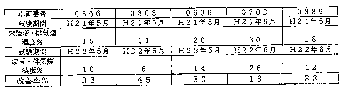
- Table 3 shows the test data comparing the previous year's data with and without the exhaust smoke concentration test on the five test vehicles at the bus office, confirming the reduction of the exhaust smoke concentration of the vehicle with the electromagnetic wave treatment device installed. It was. [Table 3] Results of smoke concentration comparison test with five diesel vehicles at the bus office
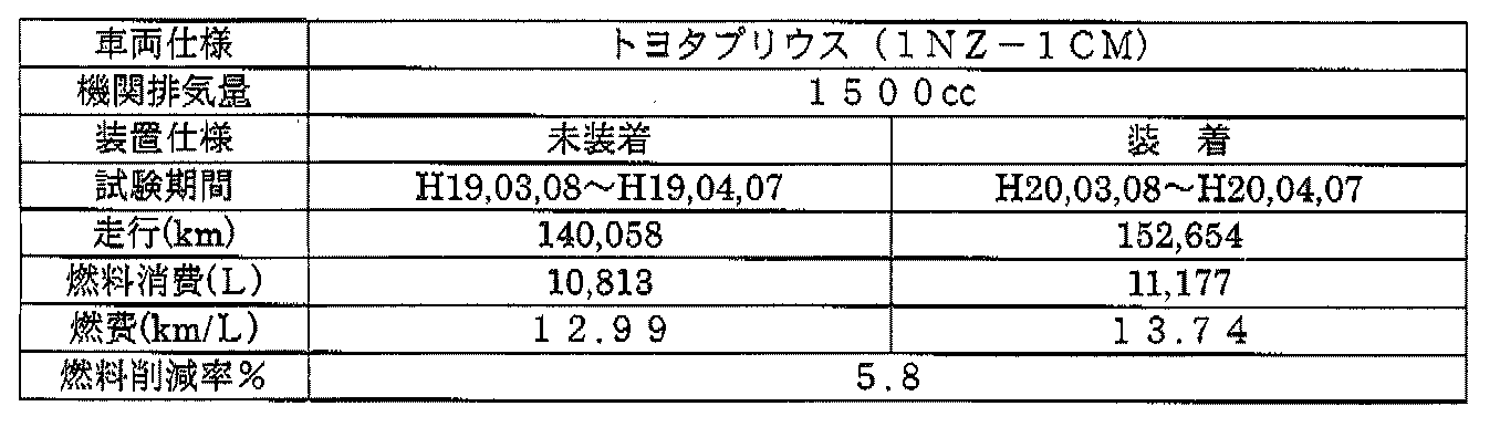
- Table 4 shows the comparative driving test data based on the data of the previous year with and without the installed vehicle in the actual driving per month for 23 gasoline fuel-efficient vehicles at the taxi office. Vehicle fuel consumption has been reduced. [Table 4] Results of driving test by taxi office (23 fuel-efficient vehicles)
- Table 5 shows the driving test data on fuel consumption with and without the actual driving per two months of a gasoline light vehicle at the mailing site. Reduction has been confirmed. In the second test, it was confirmed that the fuel efficiency returned to the original state when the electromagnetic wave treatment device was removed. [Table 5] Results of running test with a postal service gasoline light vehicle (Adachi 41-1919)
- Table 6 shows the results of the measurement of exhaust harmful substances when idling with a simple exhaust gas analyzer in the gasoline light vehicle in Table 5.
- Carbon dioxide (CO2), carbon monoxide (CO), and nitrogen oxidation contained in the exhaust gas It can be seen that there is an effect of significantly reducing exhaust harmful substances such as substances (NOx) and sulfur oxides (SOx), and it has excellent immediate effect.
- NOx substances
- SOx sulfur oxides
- the electromagnetic wave processing device of the present invention includes, for example, various combustion equipment (boiler, stove drying furnace), various internal combustion engines (gasoline). It can also be attached to an intake air section such as an air cleaner such as an engine, a diesel engine, a gas-fired engine, or a turbine engine.
Landscapes
- Engineering & Computer Science (AREA)
- Chemical & Material Sciences (AREA)
- Combustion & Propulsion (AREA)
- Mechanical Engineering (AREA)
- General Engineering & Computer Science (AREA)
- Water Supply & Treatment (AREA)
- Chemical Kinetics & Catalysis (AREA)
- Health & Medical Sciences (AREA)
- Public Health (AREA)
- Exhaust Gas After Treatment (AREA)
- Air Supply (AREA)
Abstract
Description
[表1]空気が含むことのできる水蒸気

これは気温の変化に伴い、水蒸気量が増すことにより、燃焼空気中に酸素不足が生じると共に燃焼室内で圧縮された燃焼空気中の水蒸気が水滴として凝集するために、圧縮空気に温度斑を生じさせていることが原因である。この点に関しては機械的な構造で制御するのは殆ど不可能である。
ことにより熱エネルギーを抽出する燃焼装置に供給される燃焼空気に電磁波を照射して燃焼空気中の水蒸気の水分子を励起させることを特徴とする。
この作用が、燃焼空気が圧縮された際に空気の温度分布を均一化させることになり、如いては圧縮空気の温度斑を抑制することができ、それにより着火遅れを防止し燃焼効率を高める。その結果、燃料消費量が削減され、また、排気ガスに含まれる二酸化炭素(CO2)一酸化炭素(CO)、炭化水素(HC)、窒素酸化物(NOx)、粒子状浮遊物質(PM)等の排気有害物質を低減される。
ここで「内燃機関」とは、例えば、ガソリンエンジン、ディーゼルエンジン,ガス焚きエンジン,タービンエンジン等である。
従って、各種の燃焼装置の燃焼効率を高め、燃料消費量が削減され、また、排気ガスに含まれる二酸化炭素(CO2)一酸化炭素(CO)、炭化水素(HC)、窒素酸化物(NOx)、粒子状浮遊物質(PM)等の排気有害物質を低減する。
上記照射体は、セラミックスを適宜手段により粉体化してパウダー状にし、適宜のバインダーと混合することによりペースト状に形成し、このペースト状のセラミックスを紙からなるベース材の表面に塗布して形成するものである。
請求項7記載の発明にあっては、上記基材は帯状に形成されると共に、端部には接合部が設けられていることを特徴とする。
従って、請求項7記載の発明にあっては、基材は端部に接合部が設けられていることから、帯状の基材を各種の装着対象物に巻きつけて使用することができる。
請求項9記載の発明にあっては、上記燃焼装置は内燃機関であることを特徴とする。
「内燃機関」とは、例えば、ガソリンエンジン、ディーゼルエンジン,ガス焚きエンジン,タービンエンジン等を指す。
図1はこの発明の実施の形態を示す斜視図であり、外気温を防止する矩形状の基材1内にはアルミニウム素材の遮熱体2が設けられている。
この作用により、燃焼空気が圧縮された際に空気の温度分布(分子レベル)を均一化させることになり、如いては圧縮空気の温度斑を抑制することができる。既存燃焼で必然的に発生している着火遅れを制御して、燃焼効率を改善して燃料消費量が削減されると共に排気ガスに含まれる二酸化炭素(CO2)一酸化炭素(CO)、炭化水素(HC)、窒素酸化物(NOx)、粒子状浮遊物質(PM)等の排気有害物質が低減されることとなる。
[表2]バス事業所におけるディーゼル車106台による走行試験結果

[表3]バス事業所におけるディーゼル車5台による排気煙濃度比較試験結果
[表4]タクシー事業所(低燃費車23台)による走行試験結果
[表5]郵政事業所 ガソリン軽車両(足立41れ1919)による走行試験結果

[表6]軽車両(足立41れ1919)の排気ガス分析計によるアイドリング測定結果

2 遮熱体
3 照射体
4 収納部(ポケット)
5 面状ファスナー
6 空気通路体(ダクトホース)
Claims (10)
- 被燃焼物を燃焼させることにより熱エネルギーを抽出する燃焼装置に供給される燃焼空気に電磁波を照射して燃焼空気中の水蒸気の水分子を励起させることを特徴とする燃焼空気の電磁波処理方法。
- 上記燃焼装置は内燃機関であることを特徴とする請求項1記載の燃焼空気の電磁波処理方法。
- 上記燃焼装置は発熱型燃焼機器であることを特徴とする請求項1記載の
燃焼空気の電磁波処理方法。 - 被燃焼物を燃焼させることにより熱エネルギーを抽出する燃焼装置に装着され、基材と、上記基材に取り付けられた遮熱体と、上記遮熱体上に設けられ、電磁波を燃焼空気に向けて照射する照射体と、上記照射体を収納する収納部を備えたことを特徴とする燃焼空気の電磁波処理装置。
- 上記照射体は、紙からなるベース材の表面にペースト状のセラミックスが塗布されて形成されていることを特徴とする請求項4記載の電磁波処理装置。
- 上記遮熱体は、アルミニウム製であることを特徴とする請求項4記載の燃焼空気の電磁波処理装置。
- 上記基材は帯状に形成されると共に、端部には接合部が設けられていることを特徴とする請求項4記載の燃焼空気の電磁波処理装置。
- 上記接合部は面状ファスナーであることを特徴とする請求項6記載の燃焼空気の電磁波処理装置。
- 上記燃焼装置は内燃機関であることを特徴とする請求項4記載の燃焼空気の電磁波処理装置。
- 上記燃焼装置は発熱型燃焼機器であることを特徴とする請求項4記載の
燃焼空気の電磁波処理装置。
Priority Applications (2)
| Application Number | Priority Date | Filing Date | Title |
|---|---|---|---|
| US13/201,346 US20140069395A1 (en) | 2011-05-30 | 2011-06-08 | Electromagnetic wave treatment method of water vapor in combustion air and electromagnetic wave treatment apparatus of water vapor in combustion air |
| SG2011058179A SG186044A1 (en) | 2011-05-30 | 2011-06-08 | Electromagnetic wave treatment method of water vapor in combustion air and electromagnetic wave treatment apparatus of water vapor in combustion air |
Applications Claiming Priority (2)
| Application Number | Priority Date | Filing Date | Title |
|---|---|---|---|
| JP2011-119870 | 2011-05-30 | ||
| JP2011119870A JP2012246854A (ja) | 2011-05-30 | 2011-05-30 | 燃焼空気中の水蒸気の電磁波処理方法及び燃焼空気中の水蒸気の電磁波処理装置 |
Publications (1)
| Publication Number | Publication Date |
|---|---|
| WO2012164634A1 true WO2012164634A1 (ja) | 2012-12-06 |
Family
ID=47258523
Family Applications (1)
| Application Number | Title | Priority Date | Filing Date |
|---|---|---|---|
| PCT/JP2011/003248 Ceased WO2012164634A1 (ja) | 2011-05-30 | 2011-06-08 | 燃焼空気中の水蒸気の電磁波処理方法及び燃焼空気中の水蒸気の電磁波処理装置 |
Country Status (5)
| Country | Link |
|---|---|
| US (1) | US20140069395A1 (ja) |
| JP (1) | JP2012246854A (ja) |
| HU (1) | HUP1100440A2 (ja) |
| SG (1) | SG186044A1 (ja) |
| WO (1) | WO2012164634A1 (ja) |
Families Citing this family (1)
| Publication number | Priority date | Publication date | Assignee | Title |
|---|---|---|---|---|
| CN104214790B (zh) * | 2014-05-23 | 2016-08-24 | 上海英龙国际贸易有限公司 | 用于锅炉的节能减排装置 |
Citations (6)
| Publication number | Priority date | Publication date | Assignee | Title |
|---|---|---|---|---|
| JPH0777114A (ja) * | 1993-09-03 | 1995-03-20 | Kiyoshi Hosobuchi | ディーゼル・エンジンの黒煙抑制及び燃費改善フィルター |
| JP2002054514A (ja) * | 2000-08-11 | 2002-02-20 | Hatakemoto Kanae | 燃焼効率改善装置 |
| JP2004068669A (ja) * | 2002-08-05 | 2004-03-04 | Kawabe Sangyo Kk | 車輌のエアークリーナ内空気の浄化装置と、車輌のエアークリーナ内に取付けできる空気の浄化シート |
| JP2007229672A (ja) * | 2006-03-03 | 2007-09-13 | Satoo Techno:Kk | 気体改質方法、気体改質ネット、気体改質シート、気体改質配管、燃料電池 |
| JP2008038628A (ja) * | 2006-08-01 | 2008-02-21 | Toshiharu Fukai | 排気ガス中の有害成分の低減装置 |
| JP2010121608A (ja) * | 2008-11-17 | 2010-06-03 | Aporia:Kk | 燃焼性改善用組成物資材及び組成物 |
-
2011
- 2011-05-30 JP JP2011119870A patent/JP2012246854A/ja not_active Withdrawn
- 2011-06-08 WO PCT/JP2011/003248 patent/WO2012164634A1/ja not_active Ceased
- 2011-06-08 SG SG2011058179A patent/SG186044A1/en unknown
- 2011-06-08 US US13/201,346 patent/US20140069395A1/en not_active Abandoned
- 2011-08-15 HU HU1100440A patent/HUP1100440A2/hu unknown
Patent Citations (6)
| Publication number | Priority date | Publication date | Assignee | Title |
|---|---|---|---|---|
| JPH0777114A (ja) * | 1993-09-03 | 1995-03-20 | Kiyoshi Hosobuchi | ディーゼル・エンジンの黒煙抑制及び燃費改善フィルター |
| JP2002054514A (ja) * | 2000-08-11 | 2002-02-20 | Hatakemoto Kanae | 燃焼効率改善装置 |
| JP2004068669A (ja) * | 2002-08-05 | 2004-03-04 | Kawabe Sangyo Kk | 車輌のエアークリーナ内空気の浄化装置と、車輌のエアークリーナ内に取付けできる空気の浄化シート |
| JP2007229672A (ja) * | 2006-03-03 | 2007-09-13 | Satoo Techno:Kk | 気体改質方法、気体改質ネット、気体改質シート、気体改質配管、燃料電池 |
| JP2008038628A (ja) * | 2006-08-01 | 2008-02-21 | Toshiharu Fukai | 排気ガス中の有害成分の低減装置 |
| JP2010121608A (ja) * | 2008-11-17 | 2010-06-03 | Aporia:Kk | 燃焼性改善用組成物資材及び組成物 |
Also Published As
| Publication number | Publication date |
|---|---|
| US20140069395A1 (en) | 2014-03-13 |
| HUP1100440A2 (en) | 2013-01-28 |
| SG186044A1 (en) | 2013-01-30 |
| JP2012246854A (ja) | 2012-12-13 |
Similar Documents
| Publication | Publication Date | Title |
|---|---|---|
| RU125628U1 (ru) | Многослойная система снижения токсичности отработавших газов и многослойная система дизельного окислительного нейтрализатора | |
| KR102025922B1 (ko) | 자동차 촉매 후처리 시스템 | |
| CN1784540A (zh) | 包含微粒过滤器和NOx吸收剂的贫燃料燃烧内燃机的排气系统 | |
| CN1610790A (zh) | 用于改进的内燃机排放控制的系统和方法 | |
| EP2063976A1 (en) | Washcoated particulate filter substrate | |
| BRPI0606585A2 (pt) | emissões reduzidas de combustão utilizando catalisador de combustão metálico multicomponente e filtro de particulado diesel levemente catalisado | |
| CN102505981B (zh) | 用于柴油燃料燃烧后处理系统的排放控制系统 | |
| WO2012164634A1 (ja) | 燃焼空気中の水蒸気の電磁波処理方法及び燃焼空気中の水蒸気の電磁波処理装置 | |
| JP2004138050A (ja) | ディーゼル燃料燃焼後処理システムにおける煤の酸化および灰蓄積の低減方法 | |
| CN107869378A (zh) | 清洁气体传感器的方法 | |
| CN102472137A (zh) | 控制燃烧器的燃料喷射量的方法以及废气后处理装置 | |
| KR20100116898A (ko) | 디젤내연기관용 매연저감장치 | |
| JP2004138049A (ja) | ディーゼル燃料燃焼後処理システムの動作の増進方法 | |
| JP2014034887A (ja) | ディーゼルエンジンの排気ガス処理装置及び排気ガス処理方法 | |
| KR101043103B1 (ko) | 배기가스 재연소장치 | |
| KR100942058B1 (ko) | 내연기관의 연료 절감 및 매연 저감장치 | |
| KR20250019944A (ko) | 원적외선을 방사하는 배기가스 저감장치 | |
| Hara et al. | Effects of fuel properties on the performance of advanced diesel NOx aftertreatment devices | |
| KR20110003098A (ko) | 배기가스 저감 장치 및 배기가스 저감 방법 | |
| CN202039922U (zh) | 车辆排放废气低温瞬态净化处理装置 | |
| KR100774864B1 (ko) | 디젤차량에서 촉매 유황화량 계산 로직장치 | |
| WO2006095146A1 (en) | Process and apparatus for the regeneration of a particulate filter | |
| JP2018135825A (ja) | 内燃機関 | |
| Hawley et al. | PM thermal regeneration-the potential for catalytic combustion | |
| CN101910572A (zh) | 消声器 |
Legal Events
| Date | Code | Title | Description |
|---|---|---|---|
| WWE | Wipo information: entry into national phase |
Ref document number: 1680/MUMNP/2011 Country of ref document: IN |
|
| WWE | Wipo information: entry into national phase |
Ref document number: 13201346 Country of ref document: US |
|
| 121 | Ep: the epo has been informed by wipo that ep was designated in this application |
Ref document number: 11866876 Country of ref document: EP Kind code of ref document: A1 |
|
| NENP | Non-entry into the national phase |
Ref country code: DE |
|
| 32PN | Ep: public notification in the ep bulletin as address of the adressee cannot be established |
Free format text: NOTING OF LOSS OF RIGHTS PURSUANT TO RULE 112(1) EPC (EPO FORM 1205A DATED 05/03/2014) |
|
| 122 | Ep: pct application non-entry in european phase |
Ref document number: 11866876 Country of ref document: EP Kind code of ref document: A1 |