WO2012164660A1 - スクリーン印刷版及びその使用方法 - Google Patents
スクリーン印刷版及びその使用方法 Download PDFInfo
- Publication number
- WO2012164660A1 WO2012164660A1 PCT/JP2011/062367 JP2011062367W WO2012164660A1 WO 2012164660 A1 WO2012164660 A1 WO 2012164660A1 JP 2011062367 W JP2011062367 W JP 2011062367W WO 2012164660 A1 WO2012164660 A1 WO 2012164660A1
- Authority
- WO
- WIPO (PCT)
- Prior art keywords
- sheet
- subframe
- screen printing
- printing plate
- frame
- Prior art date
- Legal status (The legal status is an assumption and is not a legal conclusion. Google has not performed a legal analysis and makes no representation as to the accuracy of the status listed.)
- Ceased
Links
Images


Classifications
-
- B—PERFORMING OPERATIONS; TRANSPORTING
- B41—PRINTING; LINING MACHINES; TYPEWRITERS; STAMPS
- B41N—PRINTING PLATES OR FOILS; MATERIALS FOR SURFACES USED IN PRINTING MACHINES FOR PRINTING, INKING, DAMPING, OR THE LIKE; PREPARING SUCH SURFACES FOR USE AND CONSERVING THEM
- B41N1/00—Printing plates or foils; Materials therefor
- B41N1/24—Stencils; Stencil materials; Carriers therefor
- B41N1/248—Mechanical details, e.g. fixation holes, reinforcement or guiding means; Perforation lines; Ink holding means; Visually or otherwise detectable marking means; Stencil units
-
- B—PERFORMING OPERATIONS; TRANSPORTING
- B41—PRINTING; LINING MACHINES; TYPEWRITERS; STAMPS
- B41F—PRINTING MACHINES OR PRESSES
- B41F15/00—Screen printers
- B41F15/14—Details
- B41F15/34—Screens, Frames; Holders therefor
- B41F15/36—Screens, Frames; Holders therefor flat
-
- H—ELECTRICITY
- H05—ELECTRIC TECHNIQUES NOT OTHERWISE PROVIDED FOR
- H05K—PRINTED CIRCUITS; CASINGS OR CONSTRUCTIONAL DETAILS OF ELECTRIC APPARATUS; MANUFACTURE OF ASSEMBLAGES OF ELECTRICAL COMPONENTS
- H05K3/00—Apparatus or processes for manufacturing printed circuits
- H05K3/10—Apparatus or processes for manufacturing printed circuits in which conductive material is applied to the insulating support in such a manner as to form the desired conductive pattern
- H05K3/12—Apparatus or processes for manufacturing printed circuits in which conductive material is applied to the insulating support in such a manner as to form the desired conductive pattern using thick film techniques, e.g. printing techniques to apply the conductive material or similar techniques for applying conductive paste or ink patterns
- H05K3/1216—Apparatus or processes for manufacturing printed circuits in which conductive material is applied to the insulating support in such a manner as to form the desired conductive pattern using thick film techniques, e.g. printing techniques to apply the conductive material or similar techniques for applying conductive paste or ink patterns by screen printing or stencil printing
- H05K3/1225—Screens or stencils; Holders therefor
Definitions
- the present invention relates to a screen printing plate used for solder paste printing for surface solder mounting by the screen printing method and a method for using the same.
- a conventional screen printing plate is disclosed as a pattern printing plate making (for example, see Patent Document 1).
- the version of Patent Document 1 uses a main frame and a sub frame and replaces the thinned sub frame.
- the present invention provides a screen printing plate that can hold a sheet at a high tension when performing screen printing, and therefore can prevent printing misalignment, and can realize better plate separation and a method of using the same.
- the present invention includes a perforated plate-shaped metal mask, a sheet on which the metal mask is bonded to one surface and a paste to be printed on a substrate can pass, and the sheet is bonded to one surface,
- a screen printing plate comprising a flat sub-frame with an opening covered and a main frame in which a placement area on which the sub-frame is to be placed is formed on the outer periphery, the main frame is described above
- a screen printing plate characterized in that it has a protruding frame portion that protrudes longer than the thickness of the sub-frame on the side where the sub-frame is placed inside the mounting area.
- the sheet when the sub-frame is placed in the placement area of the main frame, the sheet is pushed up by the protruding frame to increase the tension of the sheet, and the metal is positioned at the opening surface of the protruding frame.
- the main frame has a protruding frame portion that protrudes longer than the thickness of the subframe on the side where the subframe is placed inside the placement area.
- the sheet When placed on the main frame, the sheet is pushed out by the protruding frame. As a result, the sheet is stretched and the tension is improved, and the state is maintained. For this reason, when performing screen printing, the sheet can be held at a high tension, so that it is possible to prevent printing misalignment and to achieve better plate separation.
- the subframe unit 1 used for the screen printing plate according to the present invention includes a subframe 2, a sheet 3, and a metal mask 4.
- the subframe 2 is a frame having a flat and substantially rectangular shape, and its thickness T1 is, for example, about 5 mm.
- the subframe 2 is made of metal using, for example, aluminum.
- the sheet 3 is bonded so as to cover the opening 11 (see FIG. 3) of the subframe 2.
- the sheet 3 is bonded to one surface of the subframe 2 using an adhesive (not shown).
- This sheet 3 is called “ ⁇ ”, and is formed of, for example, polyester fiber, polyamide synthetic fiber, stainless steel, or the like.
- the sheet 3 is provided with an opening 12 that allows a paste to be printed on the substrate, such as a solder paste, to pass therethrough.
- the opening 12 is formed after bonding a metal mask 4 described later.
- the metal mask 4 is bonded to the sheet 3. Specifically, it is bonded to the surface opposite to the subframe 2 through the sheet 3 using an adhesive (not shown).
- the metal mask 4 has a perforated plate shape, and a large number of filling holes 5 are formed in the metal mask 4. This filling hole is for filling the paste at the time of printing, and the shape and position in the metal mask 4 are different for each substrate to be manufactured. Therefore, when performing screen printing, the subframe unit 1 having the most suitable metal mask 4 is selected and performed.
- the main frame 6 used for the screen printing plate according to the present invention has a predetermined thickness and a certain degree of rigidity.
- the thickness T2 is, for example, 30 mm.
- a placement region 7 on which the above-described subframe 2 is to be placed is formed on the outer peripheral edge of one surface of the main frame 2.
- a protruding frame portion 8 is formed inside the placement region 7.
- the protruding frame portion 8 has a frame shape and protrudes from the placement region 7 side of the main frame 6.
- the protruding length T3 is longer than the thickness T1 than the subframe 2, and is, for example, 10 mm to 15 mm.
- a combination of the above-described subframe 2 and main frame 6 is a screen printing plate 9 according to the present invention.
- the actual method of using the screen printing plate 9 will be described below with reference to FIGS.
- the subframe unit 1 is set on the placement area 7 side of the main frame 6 (state shown in FIG. 3). At this time, the subframe 2 is set at a position corresponding to the placement area 7. In this state, the subframe unit 1 is moved in the direction of arrow D, and the subframe 2 is placed on the placement area 7. As described above, since the protruding length T3 of the protruding frame portion 8 is longer than the thickness T1 of the subframe 2, the sheet 3 is pushed up by the protruding frame portion 8 (state of FIG. 4). As a result, the sheet 3 is stretched and its tension is increased. In this state, the metal mask 4 is held at the position of the opening surface 10 of the protruding frame 8.
- the sheet 3 is stretched and tension is improved, and the state is maintained. become. For this reason, when performing screen printing, the sheet 3 can be held at a high tension, and therefore, printing misalignment can be prevented, and better plate separation can be realized. Further, even when the subframe 2 is warped by being pulled inward by the sheet 3, the warpage is eliminated by placing it on the main frame 6, and the tension of the sheet 3 is also improved. That is, for the convenience of storage, the rigidity of the thin subframe is weakened, and the tension of the sheet 3 when the sheet 3 is bonded causes the subframe 2 to be warped and the tension of the sheet 3 is lowered. It has been solved during screen printing.
- the screen printing plate 9 according to the present invention can be applied to a conventional printing apparatus or the like.
- the metal mask 4 is opposed to the substrate, the paste is applied from the sheet 3 side, the filling hole 5 is filled with the paste, and the plate 9 is separated from the substrate for printing.
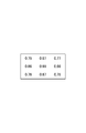
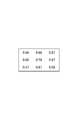
- the results of testing how much tension was improved by the present invention are shown in FIGS.
- the degree of tension of the sheet 3 was measured depending on the position of the sheet 3.
- the tension was measured using a metal mask dedicated tension gauge (MTG-08A). This tension gauge indicates that the tension is high when the numerical value is low.
- the size of the metal mask 4 was 520 mm ⁇ 420 mm.
- FIG. 5 shows the subframe 2 as it is
- FIG. 6 shows the subframe 2 mounted and fixed on the main frame without the protruding frame portion 8
- FIG. 7 shows the plate 9 according to the present invention.
Landscapes
- Engineering & Computer Science (AREA)
- Mechanical Engineering (AREA)
- Manufacturing & Machinery (AREA)
- Microelectronics & Electronic Packaging (AREA)
- Screen Printers (AREA)
- Electric Connection Of Electric Components To Printed Circuits (AREA)
Abstract
多孔板形状のメタルマスク(4)と、該メタルマスク(4)が一方の面に接着され、基板に印刷されるべきペーストが通過可能なシート(3)と、該シート(3)が一方の面に接着され、該シート(3)により開口部が覆われた扁平状のサブフレーム(2)と、該サブフレーム(2)が載置されるべき載置領域が外周縁に形成されたメインフレーム(6)とを備えたスクリーン印刷版(9)において、前記メインフレーム(6)は、前記載置領域の内側に前記サブフレーム(2)が載置される側であって前記サブフレーム(2)の厚みよりも長く突出している突き出しフレーム部(8)を有する。
Description
本発明は、スクリーン印刷法による表面半田実装用ソルダペースト印刷等に用いられるスクリーン印刷版及びその使用方法に関する。
従来のスクリーン印刷版がパターン印刷用製版として開示されている(例えば特許文献1参照)。特許文献1の版は、保管時における収容スペースを削減するため、メインフレームとサブフレームとを用い、薄型化されたサブフレームを交換するような形態としている。
しかしながら、サブフレームが薄いと剛性が弱まるため、サブフレームに接着された高分子材料からなるシートのテンションに対抗することができず、シートのテンションによってサブフレーム全体が反ってしまう。このような反りが発生すると、メタルマスクを印刷に使用したときにずれが生じる原因となる。特に、近年の部品サイズの小型化に伴い、多少のずれであっても印刷品質に与える影響は大きい。また、反りが生じるとシートのテンションも低くなるため、印刷後にメタルマスクを基板から離間させる(いわゆる「版離れ」)ときに、シートに半田等が付着したままのことがある。このため、版離れ時のスピード制御が複雑になるという問題がある。
本発明は、スクリーン印刷を行うに際してシートを高テンションに保持することができ、したがって印刷ずれを防止でき、さらに良好な版離れを実現できるスクリーン印刷版及びその使用方法を提供する。
本発明は、多孔板形状のメタルマスクと、該メタルマスクが一方の面に接着され、基板に印刷されるべきペーストが通過可能なシートと、該シートが一方の面に接着され、該シートにより開口部が覆われた扁平状のサブフレームと、該サブフレームが載置されるべき載置領域が外周縁に形成されたメインフレームとを備えたスクリーン印刷版において、前記メインフレームは、前記載置領域の内側に前記サブフレームが載置される側であって前記サブフレームの厚みよりも長く突出している突き出しフレーム部を有することを特徴とするスクリーン印刷版を提供する。
本発明はさらに、前記サブフレームを前記メインフレームの前記載置領域に載置するに際し、前記突き出しフレームで前記シートを押し上げて前記シートのテンションを高め、前記突き出しフレームの開口面の位置で前記メタルマスクを保持することを特徴とする請求項1に記載のスクリーン印刷版の使用方法を提供する。
本発明によれば、メインフレームは、載置領域の内側にサブフレームが載置される側であってサブフレームの厚みよりも長く突出している突き出しフレーム部を有しているため、サブフレームがメインフレームに載置された際、シートは突き出しフレームによって押し出される。これにより、シートが張り詰められてテンションが向上し、その状態が維持される。このため、スクリーン印刷を行うに際してシートを高テンションに保持することができ、したがって印刷ずれを防止でき、さらに良好な版離れを実現できる。
図1に示すように、本発明に係るスクリーン印刷版に用いられるサブフレームユニット1は、サブフレーム2と、シート3と、メタルマスク4とを有している。
サブフレーム2は、扁平状の略矩形形状を有するフレームであり、その厚さT1は例えば約5mmである。また、サブフレーム2は、例えばアルミニウム等を用いた金属製である。このサブフレーム2の開口部11(図3参照)を覆うようにして、シート3が接着されている。
シート3は、サブフレーム2の一方の面に対して、接着剤(不図示)を用いて接着されている。このシート3は、「紗」と称され、例えばポリエステル繊維、ポリアミド系合成繊維、あるいはステンレス金属等で形成されている。シート3には、ソルダペースト等、基板に印刷されるべきペーストを通過可能にする開口部12が設けてある。なお、この開口部12は後述するメタルマスク4を接着した後に形成される。
そして、シート3には、メタルマスク4が接着されている。具体的には、シート3を介してサブフレーム2とは反対側の面に接着剤(不図示)を用いて接着される。このメタルマスク4は多孔板形状であり、メタルマスク4には多数の充填孔5が形成されている。この充填孔は印刷時にペーストを充填するためのものであり、メタルマスク4における形状、位置は製造する基板ごとに異なっている。したがって、スクリーン印刷をする際には最も適したメタルマスク4を有するサブフレームユニット1を選択して行う。
図2に示すように、本発明に係るスクリーン印刷版に用いられるメインフレーム6は、所定の厚みを有し、ある程度の剛性を有している。その厚さT2は例えば30mmである。メインフレーム2の一方の面における外周縁には、上述したサブフレーム2が載置されるべき載置領域7が形成されている。また、この載置領域7の内側には、突き出しフレーム部8が形成されている。この突き出しフレーム部8は、メインフレーム6における載置領域7側からフレーム形状を有して突出している。その突出長さT3は、サブフレーム2より厚みT1よりも長く、例えば10mm~15mmである。
上述したサブフレーム2及びメインフレーム6を組み合わせたものが本発明に係るスクリーン印刷版9である。このスクリーン印刷版9を実際の使用方法について図3及び図4を用いて以下に説明する。
メインフレーム6の載置領域7側にサブフレームユニット1をセットする(図3の状態)。このとき、サブフレーム2は載置領域7に対応した位置にセットされる。そして、この状態で、サブフレームユニット1を矢印D方向に移動させ、サブフレーム2を載置領域7に載置する。上述したように、突き出しフレーム部8の突出長さT3はサブフレーム2の厚みT1より長いため、シート3は突き出しフレーム部8によって押し上げられる(図4の状態)。これにより、シート3は張り詰められてそのテンションが高められる。この状態では、メタルマスク4は突き出しフレーム8の開口面10の位置で保持されている。
以上のように、メインフレーム6に突き出しフレーム部8を形成し、この突き出しフレーム8を用いてシート3を押し出せば、シート3が張り詰められてテンションが向上し、その状態が維持されることになる。このため、スクリーン印刷を行うに際してシート3を高テンションに保持することができ、したがって印刷ずれを防止でき、さらに良好な版離れを実現できる。また、シート3により内側に引っ張られてサブフレーム2が反っている場合でも、メインフレーム6に載置することでその反りは解消され、シート3のテンションも向上する。すなわち、保管の便宜のために薄型のサブフレームとしてその剛性が弱まり、シート3を接着したときのシート3の張力によりサブフレーム2が反ってしまってシート3のテンションが低くなってしまう問題点は、スクリーン印刷時には解決されている。
なお、本発明に係るスクリーン印刷版9は従来の印刷装置等に適用できる。実際に印刷する場合は、基板に向けてメタルマスク4を対向させ、シート3側からペーストを塗布して充填孔5にペーストを充填させ、版9を基板から離すことによって印刷する。
本発明によってテンションがどの程度向上したかを試験した結果を図5~図7に示した。試験では、シート3のテンションがシート3の位置によってどの程度であるかを測定した。テンションの測定は、メタルマスク専用のテンションゲージ(MTG-08A)を用いた。このテンションゲージは、数値が低い方ときにテンションが高いことを示す。なお、メタルマスク4のサイズは520mm×420mmとした。
図5はサブフレーム2のまま、図6は突き出しフレーム部8を有さないメインフレームにサブフレーム2を載置して固定したもの、図7は本発明に係る版9である。数値を比較すると、本発明に係るスクリーン印刷版9のテンション値がシート3のどの位置においても低くなっていて、テンションが高められていることがわかる。したがって、本発明は突き出しフレーム部8によって効果的にシート3のテンションを高めていることが実証された。
1 サブフレームユニット
2 サブフレーム
3 シート
4 メタルマスク
5 充填孔
6 メインフレーム
7 載置領域
8 突き出しフレーム部
9 スクリーン印刷版
10 突き出しフレーム部の開口面
11 サブフレームの開口部
12 シートの開口部
2 サブフレーム
3 シート
4 メタルマスク
5 充填孔
6 メインフレーム
7 載置領域
8 突き出しフレーム部
9 スクリーン印刷版
10 突き出しフレーム部の開口面
11 サブフレームの開口部
12 シートの開口部
Claims (2)
- 多孔板形状のメタルマスクと、
該メタルマスクが一方の面に接着され、基板に印刷されるべきペーストが通過可能なシートと、
該シートが一方の面に接着され、該シートにより開口部が覆われた扁平状のサブフレームと、
該サブフレームが載置されるべき載置領域が外周縁に形成されたメインフレームと
を備えたスクリーン印刷版において、
前記メインフレームは、前記載置領域の内側に前記サブフレームが載置される側であって前記サブフレームの厚みよりも長く突出している突き出しフレーム部を有する
ことを特徴とするスクリーン印刷版。 - 前記サブフレームを前記メインフレームの前記載置領域に載置するに際し、前記突き出しフレームで前記シートを押し上げて前記シートのテンションを高め、前記突き出しフレームの開口面の位置で前記メタルマスクを保持することを特徴とする請求項1に記載のスクリーン印刷版の使用方法。
Priority Applications (2)
| Application Number | Priority Date | Filing Date | Title |
|---|---|---|---|
| PCT/JP2011/062367 WO2012164660A1 (ja) | 2011-05-30 | 2011-05-30 | スクリーン印刷版及びその使用方法 |
| TW101117970A TW201313502A (zh) | 2011-05-30 | 2012-05-21 | 絲網印刷版及其使用方法 |
Applications Claiming Priority (1)
| Application Number | Priority Date | Filing Date | Title |
|---|---|---|---|
| PCT/JP2011/062367 WO2012164660A1 (ja) | 2011-05-30 | 2011-05-30 | スクリーン印刷版及びその使用方法 |
Publications (1)
| Publication Number | Publication Date |
|---|---|
| WO2012164660A1 true WO2012164660A1 (ja) | 2012-12-06 |
Family
ID=47258546
Family Applications (1)
| Application Number | Title | Priority Date | Filing Date |
|---|---|---|---|
| PCT/JP2011/062367 Ceased WO2012164660A1 (ja) | 2011-05-30 | 2011-05-30 | スクリーン印刷版及びその使用方法 |
Country Status (2)
| Country | Link |
|---|---|
| TW (1) | TW201313502A (ja) |
| WO (1) | WO2012164660A1 (ja) |
Citations (3)
| Publication number | Priority date | Publication date | Assignee | Title |
|---|---|---|---|---|
| JPS5027911U (ja) * | 1973-07-12 | 1975-03-31 | ||
| JPS5994454U (ja) * | 1982-12-15 | 1984-06-27 | 三洋電機株式会社 | Fm・am受信機のdx−local切換回路 |
| JPH01116671U (ja) * | 1988-02-01 | 1989-08-07 |
-
2011
- 2011-05-30 WO PCT/JP2011/062367 patent/WO2012164660A1/ja not_active Ceased
-
2012
- 2012-05-21 TW TW101117970A patent/TW201313502A/zh unknown
Patent Citations (3)
| Publication number | Priority date | Publication date | Assignee | Title |
|---|---|---|---|---|
| JPS5027911U (ja) * | 1973-07-12 | 1975-03-31 | ||
| JPS5994454U (ja) * | 1982-12-15 | 1984-06-27 | 三洋電機株式会社 | Fm・am受信機のdx−local切換回路 |
| JPH01116671U (ja) * | 1988-02-01 | 1989-08-07 |
Also Published As
| Publication number | Publication date |
|---|---|
| TW201313502A (zh) | 2013-04-01 |
Similar Documents
| Publication | Publication Date | Title |
|---|---|---|
| US7513194B2 (en) | Screen mask | |
| EP2296038B1 (en) | Mask defect testing apparatus | |
| CN106029939A (zh) | 蒸镀掩模的拉伸方法、带框架的蒸镀掩模的制造方法、有机半导体元件的制造方法及拉伸装置 | |
| JP4898748B2 (ja) | スクリーン版、層間絶縁膜、回路基板、アクティブマトリックス回路基板及び画像表示装置 | |
| US20090025582A1 (en) | Screen printing method for printing a printed circuit board | |
| JP2013528322A (ja) | Fpc製品に部材プレートを付着する方法及び部材プレートテープ | |
| JP6383487B2 (ja) | スクリーン印刷の方法 | |
| JP2014117949A (ja) | スクリーンマスク | |
| US20190320536A1 (en) | Printing device and printing method for applying a viscous or pasty material | |
| WO2012164660A1 (ja) | スクリーン印刷版及びその使用方法 | |
| JP2011194866A (ja) | スクリーン印刷装置、スクリーン印刷枠及びスクリーン印刷枠調製方法 | |
| JP5615788B2 (ja) | スクリーン印刷機用スクリーン版 | |
| EP2570262A1 (en) | Stencil for printing solder paste on printed circuit board | |
| JP2013086315A5 (ja) | ||
| JP2000177262A (ja) | コンビネーション張り製版の製造方法 | |
| JP2009126159A (ja) | フィルム固定治具およびスクリーン印刷方法 | |
| KR101410633B1 (ko) | 금속판 콤비 스크린 마스크 및 그 제조방법 | |
| JP2010195413A (ja) | 保持トレー、印刷治具、及び印刷方法 | |
| JP4442132B2 (ja) | ダブルフレームコンビネーションマスクおよびその製造方法 | |
| WO2016047263A1 (ja) | メタルマスクの製造方法 | |
| KR101186538B1 (ko) | 인쇄회로기판 고정용 지그 | |
| JP2007090718A (ja) | コンビネーション版及びコンビネーション版用治具 | |
| JP2008155557A (ja) | 印刷方法および印刷装置 | |
| JP6446592B1 (ja) | コンビネーションメタルマスク版およびコンビネーションメタルマスク版用メタルマスク | |
| EP1719619A2 (en) | Method for stretching a gauze for use in screen printing |
Legal Events
| Date | Code | Title | Description |
|---|---|---|---|
| 121 | Ep: the epo has been informed by wipo that ep was designated in this application |
Ref document number: 11866562 Country of ref document: EP Kind code of ref document: A1 |
|
| NENP | Non-entry into the national phase |
Ref country code: DE |
|
| 122 | Ep: pct application non-entry in european phase |
Ref document number: 11866562 Country of ref document: EP Kind code of ref document: A1 |
|
| NENP | Non-entry into the national phase |
Ref country code: JP |