WO2012164677A1 - Dispositif de commande de moteur - Google Patents
Dispositif de commande de moteur Download PDFInfo
- Publication number
- WO2012164677A1 WO2012164677A1 PCT/JP2011/062429 JP2011062429W WO2012164677A1 WO 2012164677 A1 WO2012164677 A1 WO 2012164677A1 JP 2011062429 W JP2011062429 W JP 2011062429W WO 2012164677 A1 WO2012164677 A1 WO 2012164677A1
- Authority
- WO
- WIPO (PCT)
- Prior art keywords
- engine
- engine control
- operated
- throttle
- operating member
- Prior art date
- Legal status (The legal status is an assumption and is not a legal conclusion. Google has not performed a legal analysis and makes no representation as to the accuracy of the status listed.)
- Ceased
Links
Images




Classifications
-
- B—PERFORMING OPERATIONS; TRANSPORTING
- B60—VEHICLES IN GENERAL
- B60W—CONJOINT CONTROL OF VEHICLE SUB-UNITS OF DIFFERENT TYPE OR DIFFERENT FUNCTION; CONTROL SYSTEMS SPECIALLY ADAPTED FOR HYBRID VEHICLES; ROAD VEHICLE DRIVE CONTROL SYSTEMS FOR PURPOSES NOT RELATED TO THE CONTROL OF A PARTICULAR SUB-UNIT
- B60W10/00—Conjoint control of vehicle sub-units of different type or different function
- B60W10/04—Conjoint control of vehicle sub-units of different type or different function including control of propulsion units
- B60W10/06—Conjoint control of vehicle sub-units of different type or different function including control of propulsion units including control of combustion engines
-
- F—MECHANICAL ENGINEERING; LIGHTING; HEATING; WEAPONS; BLASTING
- F02—COMBUSTION ENGINES; HOT-GAS OR COMBUSTION-PRODUCT ENGINE PLANTS
- F02D—CONTROLLING COMBUSTION ENGINES
- F02D11/00—Arrangements for, or adaptations to, non-automatic engine control initiation means, e.g. operator initiated
- F02D11/02—Arrangements for, or adaptations to, non-automatic engine control initiation means, e.g. operator initiated characterised by hand, foot, or like operator controlled initiation means
-
- B—PERFORMING OPERATIONS; TRANSPORTING
- B60—VEHICLES IN GENERAL
- B60W—CONJOINT CONTROL OF VEHICLE SUB-UNITS OF DIFFERENT TYPE OR DIFFERENT FUNCTION; CONTROL SYSTEMS SPECIALLY ADAPTED FOR HYBRID VEHICLES; ROAD VEHICLE DRIVE CONTROL SYSTEMS FOR PURPOSES NOT RELATED TO THE CONTROL OF A PARTICULAR SUB-UNIT
- B60W10/00—Conjoint control of vehicle sub-units of different type or different function
- B60W10/18—Conjoint control of vehicle sub-units of different type or different function including control of braking systems
-
- B—PERFORMING OPERATIONS; TRANSPORTING
- B62—LAND VEHICLES FOR TRAVELLING OTHERWISE THAN ON RAILS
- B62K—CYCLES; CYCLE FRAMES; CYCLE STEERING DEVICES; RIDER-OPERATED TERMINAL CONTROLS SPECIALLY ADAPTED FOR CYCLES; CYCLE AXLE SUSPENSIONS; CYCLE SIDECARS, FORECARS, OR THE LIKE
- B62K11/00—Motorcycles, engine-assisted cycles or motor scooters with one or two wheels
-
- B—PERFORMING OPERATIONS; TRANSPORTING
- B62—LAND VEHICLES FOR TRAVELLING OTHERWISE THAN ON RAILS
- B62K—CYCLES; CYCLE FRAMES; CYCLE STEERING DEVICES; RIDER-OPERATED TERMINAL CONTROLS SPECIALLY ADAPTED FOR CYCLES; CYCLE AXLE SUSPENSIONS; CYCLE SIDECARS, FORECARS, OR THE LIKE
- B62K11/00—Motorcycles, engine-assisted cycles or motor scooters with one or two wheels
- B62K11/14—Handlebar constructions, or arrangements of controls thereon, specially adapted thereto
-
- B—PERFORMING OPERATIONS; TRANSPORTING
- B62—LAND VEHICLES FOR TRAVELLING OTHERWISE THAN ON RAILS
- B62K—CYCLES; CYCLE FRAMES; CYCLE STEERING DEVICES; RIDER-OPERATED TERMINAL CONTROLS SPECIALLY ADAPTED FOR CYCLES; CYCLE AXLE SUSPENSIONS; CYCLE SIDECARS, FORECARS, OR THE LIKE
- B62K23/00—Rider-operated controls specially adapted for cycles, i.e. means for initiating control operations, e.g. levers, grips
- B62K23/02—Rider-operated controls specially adapted for cycles, i.e. means for initiating control operations, e.g. levers, grips hand actuated
-
- F—MECHANICAL ENGINEERING; LIGHTING; HEATING; WEAPONS; BLASTING
- F02—COMBUSTION ENGINES; HOT-GAS OR COMBUSTION-PRODUCT ENGINE PLANTS
- F02D—CONTROLLING COMBUSTION ENGINES
- F02D29/00—Controlling engines, such controlling being peculiar to the devices driven thereby, the devices being other than parts or accessories essential to engine operation, e.g. controlling of engines by signals external thereto
- F02D29/02—Controlling engines, such controlling being peculiar to the devices driven thereby, the devices being other than parts or accessories essential to engine operation, e.g. controlling of engines by signals external thereto peculiar to engines driving vehicles; peculiar to engines driving variable pitch propellers
-
- F—MECHANICAL ENGINEERING; LIGHTING; HEATING; WEAPONS; BLASTING
- F02—COMBUSTION ENGINES; HOT-GAS OR COMBUSTION-PRODUCT ENGINE PLANTS
- F02N—STARTING OF COMBUSTION ENGINES; STARTING AIDS FOR SUCH ENGINES, NOT OTHERWISE PROVIDED FOR
- F02N11/00—Starting of engines by means of electric motors
- F02N11/08—Circuits specially adapted for starting of engines
- F02N11/0814—Circuits specially adapted for starting of engines comprising means for controlling automatic idle-start-stop
- F02N11/0818—Conditions for starting or stopping the engine or for deactivating the idle-start-stop mode
- F02N11/0822—Conditions for starting or stopping the engine or for deactivating the idle-start-stop mode related to action of the driver
-
- B—PERFORMING OPERATIONS; TRANSPORTING
- B62—LAND VEHICLES FOR TRAVELLING OTHERWISE THAN ON RAILS
- B62K—CYCLES; CYCLE FRAMES; CYCLE STEERING DEVICES; RIDER-OPERATED TERMINAL CONTROLS SPECIALLY ADAPTED FOR CYCLES; CYCLE AXLE SUSPENSIONS; CYCLE SIDECARS, FORECARS, OR THE LIKE
- B62K2202/00—Motorised scooters
-
- F—MECHANICAL ENGINEERING; LIGHTING; HEATING; WEAPONS; BLASTING
- F02—COMBUSTION ENGINES; HOT-GAS OR COMBUSTION-PRODUCT ENGINE PLANTS
- F02N—STARTING OF COMBUSTION ENGINES; STARTING AIDS FOR SUCH ENGINES, NOT OTHERWISE PROVIDED FOR
- F02N11/00—Starting of engines by means of electric motors
- F02N11/08—Circuits specially adapted for starting of engines
- F02N11/0814—Circuits specially adapted for starting of engines comprising means for controlling automatic idle-start-stop
- F02N11/0818—Conditions for starting or stopping the engine or for deactivating the idle-start-stop mode
- F02N11/0833—Vehicle conditions
- F02N11/0837—Environmental conditions thereof, e.g. traffic, weather or road conditions
-
- F—MECHANICAL ENGINEERING; LIGHTING; HEATING; WEAPONS; BLASTING
- F02—COMBUSTION ENGINES; HOT-GAS OR COMBUSTION-PRODUCT ENGINE PLANTS
- F02N—STARTING OF COMBUSTION ENGINES; STARTING AIDS FOR SUCH ENGINES, NOT OTHERWISE PROVIDED FOR
- F02N11/00—Starting of engines by means of electric motors
- F02N11/10—Safety devices
- F02N11/101—Safety devices for preventing engine starter actuation or engagement
-
- F—MECHANICAL ENGINEERING; LIGHTING; HEATING; WEAPONS; BLASTING
- F02—COMBUSTION ENGINES; HOT-GAS OR COMBUSTION-PRODUCT ENGINE PLANTS
- F02N—STARTING OF COMBUSTION ENGINES; STARTING AIDS FOR SUCH ENGINES, NOT OTHERWISE PROVIDED FOR
- F02N19/00—Starting aids for combustion engines, not otherwise provided for
- F02N19/005—Aiding engine start by starting from a predetermined position, e.g. pre-positioning or reverse rotation
- F02N2019/007—Aiding engine start by starting from a predetermined position, e.g. pre-positioning or reverse rotation using inertial reverse rotation
-
- F—MECHANICAL ENGINEERING; LIGHTING; HEATING; WEAPONS; BLASTING
- F02—COMBUSTION ENGINES; HOT-GAS OR COMBUSTION-PRODUCT ENGINE PLANTS
- F02N—STARTING OF COMBUSTION ENGINES; STARTING AIDS FOR SUCH ENGINES, NOT OTHERWISE PROVIDED FOR
- F02N2200/00—Parameters used for control of starting apparatus
- F02N2200/08—Parameters used for control of starting apparatus said parameters being related to the vehicle or its components
- F02N2200/0801—Vehicle speed
-
- F—MECHANICAL ENGINEERING; LIGHTING; HEATING; WEAPONS; BLASTING
- F02—COMBUSTION ENGINES; HOT-GAS OR COMBUSTION-PRODUCT ENGINE PLANTS
- F02N—STARTING OF COMBUSTION ENGINES; STARTING AIDS FOR SUCH ENGINES, NOT OTHERWISE PROVIDED FOR
- F02N2200/00—Parameters used for control of starting apparatus
- F02N2200/10—Parameters used for control of starting apparatus said parameters being related to driver demands or status
- F02N2200/101—Accelerator pedal position
-
- F—MECHANICAL ENGINEERING; LIGHTING; HEATING; WEAPONS; BLASTING
- F02—COMBUSTION ENGINES; HOT-GAS OR COMBUSTION-PRODUCT ENGINE PLANTS
- F02N—STARTING OF COMBUSTION ENGINES; STARTING AIDS FOR SUCH ENGINES, NOT OTHERWISE PROVIDED FOR
- F02N2200/00—Parameters used for control of starting apparatus
- F02N2200/10—Parameters used for control of starting apparatus said parameters being related to driver demands or status
- F02N2200/102—Brake pedal position
-
- F—MECHANICAL ENGINEERING; LIGHTING; HEATING; WEAPONS; BLASTING
- F02—COMBUSTION ENGINES; HOT-GAS OR COMBUSTION-PRODUCT ENGINE PLANTS
- F02N—STARTING OF COMBUSTION ENGINES; STARTING AIDS FOR SUCH ENGINES, NOT OTHERWISE PROVIDED FOR
- F02N2300/00—Control related aspects of engine starting
- F02N2300/20—Control related aspects of engine starting characterised by the control method
- F02N2300/2002—Control related aspects of engine starting characterised by the control method using different starting modes, methods, or actuators depending on circumstances, e.g. engine temperature or component wear
-
- F—MECHANICAL ENGINEERING; LIGHTING; HEATING; WEAPONS; BLASTING
- F02—COMBUSTION ENGINES; HOT-GAS OR COMBUSTION-PRODUCT ENGINE PLANTS
- F02N—STARTING OF COMBUSTION ENGINES; STARTING AIDS FOR SUCH ENGINES, NOT OTHERWISE PROVIDED FOR
- F02N2300/00—Control related aspects of engine starting
- F02N2300/20—Control related aspects of engine starting characterised by the control method
- F02N2300/2011—Control involving a delay; Control involving a waiting period before engine stop or engine start
-
- Y—GENERAL TAGGING OF NEW TECHNOLOGICAL DEVELOPMENTS; GENERAL TAGGING OF CROSS-SECTIONAL TECHNOLOGIES SPANNING OVER SEVERAL SECTIONS OF THE IPC; TECHNICAL SUBJECTS COVERED BY FORMER USPC CROSS-REFERENCE ART COLLECTIONS [XRACs] AND DIGESTS
- Y02—TECHNOLOGIES OR APPLICATIONS FOR MITIGATION OR ADAPTATION AGAINST CLIMATE CHANGE
- Y02T—CLIMATE CHANGE MITIGATION TECHNOLOGIES RELATED TO TRANSPORTATION
- Y02T10/00—Road transport of goods or passengers
- Y02T10/10—Internal combustion engine [ICE] based vehicles
- Y02T10/40—Engine management systems
Definitions
- the present invention relates to an engine control device that performs idle stop control.
- the present invention has been made in view of such conventional problems, and an object thereof is to provide an engine control device that improves the convenience of the driver during the continuation of the idle stop operation.
- the invention according to claim 1 is operated by a driver and is a first operation for braking the front wheel (WF) and the rear wheel (WR) of the saddle riding type vehicle (10).
- the engine control means (144) is configured such that the predetermined time elapses when both the first operation member (34L) and the second operation member (34R) are operated.
- the engine (102) is automatically stopped, and when the operations of both the first operation member (34L) and the second operation member (34R) are released, the engine (102) is restarted, and the engine ( 102) After the automatic stop, when either one of the first operating member (34L) and the second operating member (34R) is operated, the automatic stop state of the engine (102) is continued.
- the engine control device (100) wherein the throttle opening degree detecting means (116) for detecting the opening degree of the throttle (80) instructing acceleration and the saddle type Stop determination means (142) for determining stop of the vehicle (10), and the engine control means (144) includes both the first operation member (34L) and the second operation member (34R).
- the predetermined time elapses when the throttle (80) is operated and the opening degree of the throttle (80) is equal to or less than a first threshold value and the stop determination means (142) determines that the saddle riding type vehicle (10) is stopped. Then, the engine (102) is automatically stopped.
- the engine control means (144) is configured such that the opening degree of the throttle (80) is controlled by the throttle opening degree detection means (116).
- the first operating member (34L) and the second operation are detected after it is detected that the saddle type vehicle (10) is stopped by the stop determination means (142). It is characterized in that it is determined whether both members (34R) are being operated.
- the engine control means (144) is configured so that the throttle (80) has an opening degree after the engine (102) is automatically stopped. When it becomes larger than the second threshold value, the engine (102) is restarted even if one of the first operating member (34L) and the second operating member (34R) is operated.
- the engine control means (144) is configured such that the opening degree of the throttle (80) is increased after the engine (102) is automatically stopped. It is determined whether or not the opening of the throttle (80) is larger than the second threshold. If the opening of the throttle (80) is larger than the second threshold, the engine (102) is restarted and the opening of the throttle (80) is not larger than the second threshold. In this case, it is determined whether the first operating member (34L) and the second operating member (34R) are not operated, and the first operating member (34L) and the second operating member (34R) are both operated. If not operated, the engine (102) is restarted.
- the engine control means (144) includes swing back control means (146) for performing swing back control to reversely rotate the crankshaft (120) after the engine (102) is automatically stopped,
- the inertia rotation speed of the crankshaft (120) is a predetermined value or more, the engine (102) is restarted without performing the swingback control.
- the invention according to claim 7 is the engine control device (100) according to claim 1, wherein the first operation detecting means (128) for detecting the operation of the first operation member (34L), and the second operation member. (34R) further detecting a second operation detecting means (130), wherein the first operation detecting means (128) and the second operation detecting means (130) are configured to detect the first operation amount and the first operation amount.
- the operation of the first operation member (34L) and the second operation member (34R) can be detected in two stages with a second operation amount larger than one operation amount, and the operation determination means (140)
- the first operation detection means (128) detects that the operation of the first operation amount or more is detected, it is determined that the first operation member (34L) is operated, and the second operation detection means (130) is the first operation.
- the second operation detection means (130) is the first operation.
- the engine is automatically stopped when a predetermined time elapses in a state in which both the first operation member and the second operation member are operated.
- the engine can be automatically stopped based on the driver's intention to stop. Further, during the automatic stop, the engine can be kept stopped as long as at least one of the first operation member and the second operation member is operated.
- the hand of the person who wants can be made free, and the convenience can be improved. In particular, when starting off a hill or when you want to start quickly but want to stop idle and improve fuel efficiency as much as possible, for example, operate the first operating member with the left hand and operate the throttle with the right hand.
- the automatic stop operation and the start operation can be made compatible. Furthermore, since the engine is restarted when the operations of both the first operating member and the second operating member are released, the driver's intention to start can be quickly reflected in the restart of the engine.
- the straddle-type vehicle stops when the opening degree of the throttle is equal to or smaller than the first threshold value when both the first operation member and the second operation member are operated.
- the engine is automatically stopped when a predetermined time elapses, so that the driver's intention to stop can be accurately detected.
- the first operation member and the second operation member Since it is determined whether or not both are operated, it is possible to prevent the engine from being automatically stopped when coasting while both the first operating member and the second operating member are being operated.
- the engine when the throttle opening is larger than the second threshold value, the engine is restarted even if one of the first operation member and the second operation member is operated. Therefore, the engine can be restarted smoothly even when starting on a slope.
- the determination of whether or not to restart the engine gives priority to the throttle opening over the operation of the first operation member and the second operation member, so the driver starts.
- the intention can be quickly reflected in the engine restart.
- the engine when the inertial rotation of the crankshaft after the automatic stop of the engine is equal to or greater than the predetermined value, the engine is restarted without performing the swingback control. Can be started.
- the seventh aspect of the present invention when the first operation member and the second operation member are operated by the first operation amount or more, it is determined that the first operation member and the second operation member are operated.
- the operation of the first operation member and the second operation member can be easily maintained without the driver getting tired by the operation of the operation member and the second operation member.
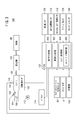
- FIG. 1 is an external left side view of a saddle riding type vehicle having an engine control device of an embodiment. It is a right side principal part enlarged view of a handle. It is a schematic block diagram of a throttle-by-wire engine control device. It is a flowchart which shows the operation
- movement of idle stop control. 6 is a sub-flowchart showing an operation of a stop determination process in step S12 of FIG. It is a flowchart which shows the restarting operation
- FIG. 1 is an external left side view of a saddle riding type vehicle 10 having an engine control device of an embodiment.
- “L” is attached to the reference symbol on the left and “R” is attached to the reference symbol on the right.
- the vehicle body frame 12 includes a head pipe 14, a down frame 16 extending downward from the head pipe 14, a pair of left and right lower frames 18L and 18R extending from the lower part of the down frame 16 to the rear of the vehicle, It has seat frames 22L and 22R for supporting the seat 20 extending rearward and upward from the rear ends of the lower frames 18L and 18R.
- a cross frame 24 is suspended between a pair of left and right lower frames 18L and 18R, and a front cross frame 26 is connected between the front of the cross frame 24 and a pair of left and right lower frames 18L and 18R. 26 is connected to the lower end of the down frame 16. Thereby, the down frame 16 can be reinforced by the front cross frame 26.
- the head pipe 14 pivotally supports a steering stem 28, front forks 30 ⁇ / b> L and 30 ⁇ / b> R that pivotally support a front wheel WF are connected to the lower end of the steering stem 28, and a handle 32 is attached to the upper end of the steering stem 28. .
- a throttle which will be described later, is provided on the right side of the handle 32, and the driver can instruct acceleration by operating the throttle.
- the output of the engine which will be described later, is controlled according to the operation of the throttle.
- the handle 32 is provided with brake levers 34L and 34R.
- the brake lever (hereinafter referred to as rear brake lever) 34L instructs braking of the rear wheel WR
- the brake lever (hereinafter referred to as front brake lever) 34R is Instructing braking of the front wheel WF.
- the rear brake lever (first operation member) 34L is operated, the rear wheel brake 36 is actuated in response to the operation to generate a braking force on the rear wheel WR, and when the front brake lever (second operation member) 34R is operated.
- the front wheel brake 38 is activated to generate a braking force on the front wheel WF.
- a swing 42 is swingably attached.
- the unit swing 42 also has a function as a swing arm, and left and right cushion units 44L and 44R are provided between the seat frames 22L and 22R and the unit swing 42.
- the unit swing 42 is provided with an air cleaner 46.
- a power unit 48 including an engine and a transmission (not shown) is provided at an intermediate portion of the vehicle body frame 12.
- the power unit 48 and the unit swing 42 are integrally provided.
- a center stand 49 is provided below the unit swing 42.
- a side stand 51 that is provided in front of the unit swing 42 and supports the saddle riding type vehicle 10 in a state of being tilted to the left is provided on the left side.
- the vehicle body frame 12 of the saddle riding type vehicle 10 is covered with a vehicle body cover 50.
- the vehicle body cover 50 includes a front cover 52 that covers the front of the vehicle, a center cowl 54 that is attached to the top of the front cover 52, and a front cover.
- a tunnel member provided between the left and right side covers 56L, 56R extending from the cover 52 to the rear of the vehicle body and the left and right side covers 56L, 56R in front of the seat 20 and connected to the center cowl 54.
- left and right under covers 62L, 62R which are arranged below the left and right side covers 56L, 56R and have left and right steps 60L, 60R on which the driver puts his feet, and from the left and right side covers 56L, 56R below the seat 20
- Left and right rear side covers 64L and 64R extending in the vehicle front-rear direction.
- the vehicle body cover 50 is attached to the vehicle body frame 12.
- a windshield 66 is attached to the top of the front cover 52, a front fender 68 is provided above the front wheel WF, and a rear fender 70 is provided above the rear wheel WR.
- the side stand 51 is provided with a stand sensor 72 that detects whether the side stand 51 has been lowered.
- FIG. 2 is an enlarged view of a main part on the right side of the handle 32.
- a throttle 80 is provided on the right side of the handle 32, and the throttle 80 is rotatable.
- a case 84 provided with an idle stop mode changeover switch 82 is attached to the left side of the throttle 80. The driver can select either the idle stop execution mode or the idle stop prohibition mode by operating the idle stop mode changeover switch 82.
- the idle stop execution mode is a mode in which execution of the automatic stop (idle stop) of the engine is permitted if a certain condition is satisfied, and the idle stop prohibit mode is an idle state even if the certain condition is satisfied. This mode prohibits execution of stop.
- the case 84 is provided with a starter switch 86 for starting the engine.
- FIG. 3 is a schematic configuration diagram of an engine control apparatus 100 of a throttle-by-wire (TBW) system.
- the engine control apparatus 100 includes an engine 102, a throttle valve 106 provided in an intake pipe 104, and an injector (fuel injection apparatus) that injects fuel to generate an air-fuel mixture that is taken into a combustion chamber (not shown) of the engine 102. 108 and a spark plug (ignition device) 110 for igniting the air-fuel mixture in the fuel chamber.
- the air-fuel mixture is a mixture of air and fuel.
- the injector 108 injects fuel into the air sucked through the throttle valve 106 that adjusts the amount of intake air into the combustion chamber to generate an air-fuel mixture.
- the generated air-fuel mixture flows into the combustion chamber of the engine 102 and is ignited by the spark plug 110 so that the air-fuel mixture burns, whereby the engine 102 converts combustion energy into power.
- the motor 112 adjusts the opening degree of the throttle valve 106 and is driven by a driver 114.
- the throttle valve 106 is opened according to the opening degree of the throttle 80.
- the opening degree of the throttle 80 is substantially zero, the opening degree of the throttle valve 106 is adjusted to the initial opening degree.
- the number of revolutions of the crankshaft 120 of the engine 102 when the opening of the throttle valve 106 is the initial degree of opening is referred to as an idle speed, and the state of the engine 102 at this time is referred to as an idle state.
- a throttle opening sensor (throttle opening detecting means) 116 detects the opening of the throttle 80
- a throttle valve opening sensor (throttle valve opening detecting means) 118 detects the opening of the throttle valve 106.
- the crankshaft 120 is an output shaft of the engine 102 and converts a reciprocating motion of a piston (not shown) of the engine 102 into a rotational force.
- the crankshaft 120 rotates according to the driving of the engine 102, and the rotation speed is determined according to the driving force of the engine 102.
- a rotational speed sensor (rotational speed detection means) 122 detects the rotational speed of the crankshaft 120 (hereinafter referred to as engine rotational speed).
- the rotational force of the crankshaft 120 is transmitted to the transmission 124, and the transmission 124 transmits the transmitted rotational force to the rear wheels WR while changing the transmission gear ratio (reduction ratio).
- the engine control apparatus 100 includes a vehicle speed sensor 126 that detects the number of rotations of the rear wheel WR, a rear brake sensor (first operation detecting means) 128 that detects whether the rear brake lever 34L is operated, and an operation that is performed by the front brake lever 34R. It further has a front brake sensor (second operation detecting means) 130 for detecting whether or not, an ECU (Engine Control Unit) 132, and a storage unit 134 for storing information.
- the ECU 132 is a control device that controls the engine control device 100 as a whole.
- the ECU 132 includes an operation determination unit 140, a stop determination unit 142, and an engine control unit 144.
- the ECU 132 includes a clock circuit and also has a function as a timer for measuring time.
- the operation determination unit (operation determination means) 140 determines the operation state of the rear brake lever 34L and the front brake lever 34R. Specifically, the operation determination unit 140 determines whether or not the rear brake lever 34L is operated and whether or not the front brake lever 34R is operated based on detection signals of the rear brake sensor 128 and the front brake sensor 130.
- the stop determination unit (stop determination unit) 142 determines whether the saddle riding type vehicle 10 has stopped. Specifically, the stop determination unit 142 determines whether the saddle riding type vehicle 10 has stopped based on the vehicle speed detected by the vehicle speed sensor 126.
- the engine control unit (engine control means) 144 controls the driving of the engine 102, and automatically stops (idle stop) and restarts the engine 102 according to the operation state of the rear brake lever 34L and the front brake lever 34R. To control. Specifically, the engine control unit 144 automatically stops the engine 102 when a predetermined time elapses with both the rear brake lever 34L and the front brake lever 34R being operated. The engine control unit 144 continues the automatic stop state of the engine 102 when either the rear brake lever 34L or the front brake lever 34R is operated after the engine 102 is automatically stopped, and the rear brake lever 34L and the front brake When both operations of the lever 34R are released, the engine 102 is restarted.
- the idle stop is when the engine 102 is stopped until a driver is instructed to start when certain conditions such as stopping of the saddle riding type vehicle 10 are established in an idle state. , Carbon dioxide (CO 2 ) emissions and fuel consumption are suppressed.
- CO 2 Carbon dioxide
- the engine control unit 144 determines the opening degree of the throttle 80 detected by the throttle opening degree sensor 116 or the throttle valve opening degree sensor 118 (hereinafter, the opening degree of the throttle 80, the throttle opening degree).
- the opening degree of the valve 106 is collectively referred to as a throttle opening degree) and the determination result of the stop determination unit 142 may be considered.
- the throttle opening is equal to or less than the first threshold value, and the stop determination unit 142 determines that the saddle riding type vehicle 10 is stopped, the predetermined time When the time elapses, the engine 102 may be automatically stopped.
- the engine control unit 144 may consider the throttle opening detected by the throttle opening sensor 116 or the throttle valve opening sensor 118. . For example, when the throttle opening is larger than the second threshold value, the engine 102 may be restarted even if either the rear brake lever 34L or the front brake lever 34R is operated.
- the first threshold value and the second threshold value may be the same value, or may be different values such that the first threshold value ⁇ the second threshold value.
- the engine control unit 144 includes a swingback control unit (swingback control means) 146, and the swingback control unit 146 performs swingback control that reversely rotates the crankshaft 120 to a predetermined position after the engine 102 is automatically stopped. .
- the swingback control unit 146 drives a starter motor (not shown) to reverse the crankshaft 120 to a predetermined position.
- the engine control unit 144 causes the crankshaft 120 that has been reversed to a predetermined position after the swingback control to rotate normally by driving the starter motor, and restarts the engine 102.
- the crankshaft 120 is reversely rotated (swinged back) to a predetermined position, so the run-up period to the compression top dead center is lengthened, and the compression top dead center is overcome first.
- the rotational speed of the crankshaft 120 can be increased.
- the engine control unit 144 When the engine control unit 144 restarts the engine 102 and the inertia rotation speed of the crankshaft 120 is equal to or greater than a predetermined value, the engine control unit 144 prohibits the swingback control by the swingback control unit 146 and immediately restarts the engine 102. Let That is, when the inertia rotation speed of the crankshaft 120 is equal to or greater than a predetermined value, the engine 102 is restarted without performing the swingback control. On the contrary, when the inertia rotation speed of the crankshaft 120 is lower than a predetermined value, the engine 102 is restarted after performing the swing back control.
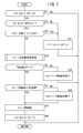
- the operation determination unit 140 determines whether or not the rear brake lever 34L has been operated (step S1). This determination is made based on the detection signal detected by the rear brake sensor 128.
- step S2 When it is determined in step S1 that the rear brake lever 34L is not operated, the operation determination unit 140 determines whether or not the front brake lever 34R is operated (step S2). This determination is made based on the detection signal detected by the front brake sensor 130.
- step S3 a waiting process is performed until the next execution timing arrives.
- step S1 the operation shown in the flowchart of FIG. 4 is performed from step S1.
- step S1 waiting processing is performed until the next execution timing comes.
- the value of the operation state flag is stored in the operation state flag storage area of the storage unit 134.
- step S5 determines whether or not the front brake lever 34R is operated.
- the operation determination unit 140 determines the operation state of the rear brake lever 34L and the front brake lever 34R, and determines the value of the operation state flag according to the determined operation state.
- the engine control unit 144 determines whether or not the idle stop execution mode is currently selected (step S11). That is, it is determined whether or not the idle stop execution mode is selected by the idle stop mode changeover switch 82.
- step S11 If it is determined in step S11 that the idle stop execution mode is not selected, that is, the idle stop prohibit mode is selected, the process returns to step S11. Therefore, when the idle stop prohibit mode is selected, the idle stop control is not performed.
- step S11 a waiting process is performed until the next execution timing comes, and when the next execution timing comes, the operation shown in the flowchart of FIG. 5 is performed from step S11. Hereinafter, when returning to step S11, the waiting process is performed until the next execution timing comes.
- step S11 if it is determined in step S11 that the idle stop execution mode is selected, the stop determination unit 142 performs a stop determination process for determining whether or not the saddle riding type vehicle 10 is stopped (step S12). This stop determination process will be described later.
- the engine control unit 144 determines whether or not the saddle riding type vehicle 10 is determined to be stopped by the stop determination process (step S13). Specifically, the engine control unit 144 determines that the saddle riding type vehicle 10 is stopped when the stop determination flag is set to 1 by the stop determination process, and stops when the stop determination flag is set to 0. Judge that it is not.
- step S14 determines whether or not the throttle opening is equal to or less than the first threshold (step S14).
- this first threshold value is set to, for example, 1 degree (0 degree if it is not TBW, that is, fully closed), whether or not the driver intends to stop (whether the throttle 80 is not operated by the driver) or not. Can be determined.
- step S14 determines whether or not the throttle opening is equal to or smaller than the first threshold. That is, in step S15, it is determined whether or not both the rear brake lever 34L and the front brake lever 34R are operated. Thereby, it can be determined whether or not the driver has a will to stop.
- step S13 If it is determined in step S13 that the saddle riding type vehicle 10 is not stopped, if it is determined in step S14 that the throttle opening is not equal to or less than the first threshold value, it is determined in step S15 that the operation state flag is not 3. In this case, that is, when any of the conditions for performing the idle stop is not satisfied, the engine control unit 144 resets and restarts the first timer (step S16), and returns to step S11.
- step S15 when it is determined in step S15 that the operation state flag is 3, that is, when it is determined that all the conditions for performing the idle stop are satisfied, the engine control unit 144 measures the time counted by the first timer. It is determined whether t1 is 3 seconds or longer (step S17). In step S17, a predetermined period of time is satisfied in a state in which all conditions for stopping the vehicle (the vehicle is stopped, the throttle opening is equal to or smaller than the first threshold, and both brake levers are operated) are satisfied. It is judged whether or not.
- step S17 it is determined whether or not the time t1 measured by the first timer is 3 seconds or more, but is not limited to 3 seconds. In short, it may be determined whether the time t1 counted by the first timer is equal to or longer than a certain time.
- step S17 when it is determined that the time t1 measured by the first timer is not 3 seconds or more, that is, it is determined that the time that has elapsed in a state where all the conditions for performing the idle stop are satisfied is less than the predetermined time. Then, it returns to step S11.
- step S17 if it is determined in step S17 that the time t1 measured by the first timer is 3 seconds or more, the engine control unit 144 executes idle stop control (step S18). Thereby, the engine 102 stops.
- the idle stop control is a process for prohibiting fuel injection by the injector 108, prohibiting ignition by the spark plug 110, and the like, so that the engine 102 can be stopped.
- the engine control unit 144 sets the idle stop flag to 1 (step S19) and returns to step S1.
- the value of the idle stop flag is stored in the idle stop flag storage area of the storage unit 134.
- the idle stop flag is 1, it indicates that the engine 102 is stopped by the idle stop control, and when the idle stop flag is 0, other states are indicated.
- the idle stop flag is set to 0 as an initial value. Further, since the operation shown in the flowchart of FIG. 5 is executed while the engine 102 is being driven, the operation shown in the flowchart of FIG. 5 is not executed even after returning to step S1 after the idle stop control is performed.
- the saddle riding type vehicle 10 is stopped while the engine 102 is being driven, the throttle opening is equal to or smaller than the first threshold (the engine 102 is in an idle state), the rear brake lever 34L and the front
- the driver's intention to stop can be accurately detected, and the driver's intention to stop Based on this, the engine 102 can be idle-stopped. It is possible to prevent the engine 102 from being automatically stopped when coasting with both the rear brake lever 34L and the front brake lever 34R being operated.
- the idle stop control is performed if all of the three conditions that the throttle opening is equal to or less than the first threshold, the saddle riding type vehicle 10 is stopped, and both the rear brake lever 34L and the front brake lever 34R are operated are satisfied. However, the condition of the operation state of the brake lever may be changed to a condition that at least one of the rear brake lever 34L and the front brake lever 34R is operated. If it is determined in step S14 in FIG. 5 that the throttle opening is equal to or smaller than the first threshold value, an operation for determining the operation state of the rear brake lever 34L and the front brake lever 34R shown in the flowchart of FIG. You may progress to step S15.
- step S12 of FIG. 5 the operation of the stop determination process in step S12 of FIG. 5 will be described according to the sub-flowchart shown in FIG.
- the stop determination process is started in step S12 of FIG. 5, the process proceeds to step S21 of FIG. 6, and the stop determination unit 142 determines whether or not the vehicle speed detected by the vehicle speed sensor 126 is a predetermined value (for example, 3 km / s) or less. Determine whether.
- a predetermined value for example, 3 km / s
- step S23 the process proceeds to step S13 in FIG.
- the value of the stop determination flag is stored in the stop determination flag storage area of the storage unit 134.
- the stop determination flag is set to 0 as an initial value.
- step S21 if it is determined in step S21 that the detected vehicle speed is less than or equal to the predetermined value, it is determined whether or not the time t2 counted by the second timer is 1 second or more (step S24).
- step S24 it is determined whether or not the time t2 measured by the second timer is 1 second or longer, but is not limited to 1 second. In short, it may be determined whether the time t2 measured by the second timer is equal to or longer than a certain time.
- step S24 it is determined whether or not a certain time has passed in a state where the vehicle speed is a predetermined value or less.
- step S24 If it is determined in step S24 that the time t2 counted by the second timer is not 1 second or more, that is, if it is determined that the elapsed time in a state where the vehicle speed is equal to or lower than the predetermined value is less than the predetermined time, the process proceeds to step S23. Thus, the stop determination flag is set to 0, and the process proceeds to step S13 in FIG.
- the vehicle speed is equivalent to “0”. Whether the vehicle 10 is stopped can be determined with high accuracy.
- the engine control unit 144 determines whether or not the idle stop flag is 1 (step S31). That is, it is determined whether or not the engine 102 is stopped by the idle stop control.
- step S31 If it is determined in step S31 that the idle stop flag is not 1, that is, if it is determined that the idle stop flag is 0, the process directly returns to step S31. Therefore, when the engine 102 is not stopped by the idle stop control, the engine 102 is not restarted by the operation shown in the flowchart of FIG. Returning to step S31, a waiting process is performed until the next execution timing arrives. When the next execution timing arrives, the operation shown in the flowchart of FIG. 7 is performed from step S31. Hereinafter, when returning to step S31, the waiting process is performed until the next execution timing comes.
- step S31 If it is determined in step S31 that the idle stop flag is 1, the engine control unit 144 determines whether or not the idle stop execution mode is selected (step S32). When the idle stop prohibit mode is selected, the idle stop state is prohibited, and therefore it is not necessary to restart the engine 102 in step S39 in FIG.
- step S32 determines whether or not the idle stop execution mode is selected. This determination is made based on the detection signal detected by the stand sensor 72. When the side stand 51 is down, the driver can assume that the driving of the saddle riding type vehicle 10 is finished, and there is no need to restart the engine 102 in step S39 of FIG.
- step S34 If it is determined in step S33 that the side stand 51 has not been lowered, the engine control unit 144 performs an engine restart determination process (step S34). The engine restart determination process will be described later.
- the engine control unit 144 determines whether or not it is determined to restart the engine 102 by the engine restart determination process (step S35). Specifically, the engine control unit 144 determines that the engine 102 is to be restarted when the restart flag is set to 1 by the engine restart determination process, and the engine 102 when the restart flag is set to 0. It is determined that no restart is performed. If it is determined in step S35 that the engine 102 is not restarted, swingback control is executed (step S36), and the process returns to step S31. Thereby, it is possible to prepare for restart of the engine 102. When the swingback control is completed, the engine 102 is kept stopped without performing the swingback control.
- step S35 when it is determined in step S35 that the engine 102 is to be restarted, the continuation of the idle stop is stopped and the engine 102 is restarted.
- the piston can overcome the compression top dead center without performing swingback control.
- step S35 if it is determined in step S35 that the engine 102 is to be restarted, the engine control unit 144 first determines whether or not the current engine speed detected by the speed sensor 122 is greater than or equal to a predetermined value. (Step S37). Since the engine 102 is currently stopped, even if the crankshaft 120 is rotating, the engine 102 is rotating due to inertia.
- step S37 If it is determined in step S37 that the engine speed is not equal to or greater than the predetermined value, the swingback control unit 146 performs swingback control (step S38), and then the engine control unit 144 restarts the engine 102 (step S38). S39). If the engine speed is not equal to or higher than a predetermined value, the piston may not be able to get over the compression top dead center, so the crankshaft 120 is reversed (swinged back) to a predetermined position by the starter motor. Thereby, the run-up period to the compression top dead center can be lengthened, and the piston can get over the compression top dead center.
- step S36 the crankshaft 120 is rotated forward by driving the starter motor, and the engine 102 is restarted by controlling the injector 108 and the spark plug 110.
- the opening degree of the throttle valve 106 is also controlled according to the throttle opening degree detected by the throttle opening degree sensor 116. Thereby, the engine 102 can be restarted smoothly. Even if it is determined that the engine speed is not equal to or greater than the predetermined value, if the swingback control has already been executed in step S36, the process directly returns to step S39 without performing the swingback control in step S38. You may go on.
- step S39 the engine control unit 144 drives the starter motor to rotate the crankshaft 120 in the normal direction and controls the injector 108 and the spark plug 110 to restart the engine 102. Thereby, the engine 102 can be restarted quickly.
- step S39 When the engine 102 is restarted in step S39, the idle stop flag is set to 0 (step S40), and the process returns to step S31.
- the driver starts the engine 102 by operating the starter switch 86 while operating the rear brake lever 34L or the front brake lever 34R. Can do.
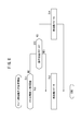
- step S34 in FIG. 7 the operation of the engine restart determination process in step S34 in FIG. 7 will be described according to the flowchart shown in FIG.
- the process proceeds to step S51 in FIG. 8, and the engine control unit 144 determines whether or not the throttle opening detected by the throttle opening sensor 116 is larger than the second threshold value. Judging.
- step S51 it is determined whether or not the throttle 80 has been operated by the driver.
- the second threshold value is preferably a value equal to or greater than the first threshold value.
- the engine 102 is restarted in step S39 in FIG. 7 even if either the rear brake lever 34L or the front brake lever 34R is operated.
- the engine 102 can be restarted smoothly even when starting on a slope.
- the value of the restart flag is stored in the restart flag storage area of the storage unit 134.
- the driver When the throttle opening is larger than the second threshold value, the driver is operating the throttle 80. In such a case, the driver operates both the rear brake lever 34L and the front brake lever 34R. It is unlikely that they are operating at the same time.
- step S53 it is determined whether or not the operation state flag is 0 (step S53).
- step S53 if it is determined in step S53 that the operation state flag is not 0, that is, if at least one of the rear brake lever 34L and the front brake lever 34R is operated, the engine control unit 144 sets the restart flag to 0 ( The restart flag is set to 0) (step S54). Accordingly, when at least one of the rear brake lever 34L and the front brake lever 34R is operated and the throttle 80 is not operated by the driver, the engine 102 is not restarted. The idle stop (the engine 102 is stopped) can be continued, and the driver's desired hand among the left and right hands of the driver can be freed, thereby improving convenience.
- the determination of whether or not to restart the engine 102 gives priority to the throttle opening over the operation of the rear brake lever 34L and the front brake lever 34R. Can be reflected.
- step S51 of FIG. 8 If it is determined in step S51 of FIG. 8 that the throttle opening is equal to or smaller than the second threshold value, the operation of determining the operation state of the rear brake lever 34L and the front brake lever 34R shown in the flowchart of FIG. You may progress to step S53. Further, the order may be changed so that the determination in step S53 is performed before step S51.
- the rear brake sensor 128 and the front brake sensor 130 will be briefly described. Since the rear brake sensor 128 and the front brake sensor 130 have the same configuration, in this embodiment, the rear brake sensor 128 will be described, and the description of the front brake sensor 130 will be omitted.
- the rear brake sensor 128 has a first switch and a second switch (not shown) that output an ON signal when the rear brake lever 34L is operated.
- the first switch is a switch that outputs an ON signal when the rear brake lever 34L is operated for a first operation amount or more by the driver
- the second switch is a second that is larger than the first operation amount by the driver. This switch outputs an ON signal when the rear brake lever 34L is operated more than the operation amount. Therefore, in order to turn on the second switch, it is necessary to increase the operation amount of the rear brake lever 34L rather than turning on the first switch.
- the rear brake sensor 128 is a sensor that can detect the operation of the rear brake lever 34L in two stages of the first operation amount and the second operation amount.
- the front brake sensor 130 is a sensor that can detect the operation of the front brake lever 34R in two stages of the first operation amount and the second operation amount. Note that, for example, only one brake sensor may detect a two-stage operation, such as only the rear brake sensor 128 that can detect a two-stage operation.
- step S1 in the flowchart of FIG.
- step S2 and step S5 in the flowchart of FIG. 4 it is determined that the front brake lever 34R has been operated.
- the operation determination unit 140 determines that the rear brake lever 34L and the front brake lever 34R are operated when the rear brake lever 34L and the front brake lever 34R are operated by the first operation amount or more.
- the operation of the rear brake lever 34L and the front brake lever 34R can be easily maintained without causing the driver to become tired by the operation of the rear brake lever 34L and the front brake lever 34R for executing the idle stop and continuing the idling stop. .
- the stand sensor 72 for detecting whether or not the side stand 51 is lowered is provided.
- a center stand sensor for detecting whether or not the center stand 49 is lowered may be provided.
- the determination in step S33 may determine whether the center stand 49 has been lowered, or may determine whether at least one of the center stand 49 and the side stand 51 has been lowered.
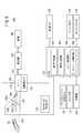
- FIG. 9 is a schematic configuration diagram of an engine control apparatus 100 that is not a TBW system.
- symbol is attached about the structure similar to FIG. 3, and description is abbreviate
- the throttle 80 and the throttle valve 106 are connected by a wire 150, and the throttle valve 106 is opened according to the operation of the throttle 80. That is, when the throttle 80 is operated, the throttle valve 106 is opened by the wire 150.
- the opening degree of the throttle 80 is 0 degree
- the opening degree of the throttle valve 106 is 0 degree.
- the intake pipe 104 is provided with a bypass passage 105a, and an idle air control valve 105b is provided in the bypass passage 105a.
- the throttle valve 106 is fully closed (the opening degree of the throttle valve 106 is 0 degree), so that the air can be sent to the bypass passage 105a by adjusting the opening degree of the idle air control valve 105b.
- the engine speed is maintained at the idle speed.
- a continuously variable transmission for example, a V-belt type continuously variable transmission
- a continuously variable transmission for example, a V-belt type continuously variable transmission
Landscapes
- Engineering & Computer Science (AREA)
- Mechanical Engineering (AREA)
- Chemical & Material Sciences (AREA)
- Combustion & Propulsion (AREA)
- General Engineering & Computer Science (AREA)
- Transportation (AREA)
- Control Of Vehicle Engines Or Engines For Specific Uses (AREA)
- Output Control And Ontrol Of Special Type Engine (AREA)
Abstract
Priority Applications (5)
| Application Number | Priority Date | Filing Date | Title |
|---|---|---|---|
| US14/122,021 US9114797B2 (en) | 2011-05-31 | 2011-05-31 | Engine control device |
| JP2013517737A JP5547344B2 (ja) | 2011-05-31 | 2011-05-31 | エンジン制御装置 |
| EP11866672.6A EP2716896B1 (fr) | 2011-05-31 | 2011-05-31 | Dispositif de commande de moteur |
| PCT/JP2011/062429 WO2012164677A1 (fr) | 2011-05-31 | 2011-05-31 | Dispositif de commande de moteur |
| CN201180071243.9A CN103562526B (zh) | 2011-05-31 | 2011-05-31 | 发动机控制装置 |
Applications Claiming Priority (1)
| Application Number | Priority Date | Filing Date | Title |
|---|---|---|---|
| PCT/JP2011/062429 WO2012164677A1 (fr) | 2011-05-31 | 2011-05-31 | Dispositif de commande de moteur |
Publications (1)
| Publication Number | Publication Date |
|---|---|
| WO2012164677A1 true WO2012164677A1 (fr) | 2012-12-06 |
Family
ID=47258563
Family Applications (1)
| Application Number | Title | Priority Date | Filing Date |
|---|---|---|---|
| PCT/JP2011/062429 Ceased WO2012164677A1 (fr) | 2011-05-31 | 2011-05-31 | Dispositif de commande de moteur |
Country Status (5)
| Country | Link |
|---|---|
| US (1) | US9114797B2 (fr) |
| EP (1) | EP2716896B1 (fr) |
| JP (1) | JP5547344B2 (fr) |
| CN (1) | CN103562526B (fr) |
| WO (1) | WO2012164677A1 (fr) |
Cited By (5)
| Publication number | Priority date | Publication date | Assignee | Title |
|---|---|---|---|---|
| US20130345935A1 (en) * | 2012-06-19 | 2013-12-26 | Fu Ling Chang | Method and device for vehicle stop and starting and position-lamps display |
| WO2015012325A1 (fr) * | 2013-07-25 | 2015-01-29 | 株式会社エフ・シ-・シ- | Véhicule du type à selle |
| WO2015012326A1 (fr) * | 2013-07-25 | 2015-01-29 | 株式会社エフ・シ-・シ- | Véhicule de type à selle |
| JP2016023559A (ja) * | 2014-07-17 | 2016-02-08 | スズキ株式会社 | エンジン始動制御装置 |
| WO2023053351A1 (fr) * | 2021-09-30 | 2023-04-06 | 本田技研工業株式会社 | Véhicule du type à selle |
Families Citing this family (10)
| Publication number | Priority date | Publication date | Assignee | Title |
|---|---|---|---|---|
| JP6151799B2 (ja) * | 2013-12-02 | 2017-06-21 | 川崎重工業株式会社 | 鞍乗り型車両 |
| CN104265464B (zh) * | 2014-09-17 | 2016-08-31 | 林德(中国)叉车有限公司 | 发动机油门控制机构 |
| JP6391007B2 (ja) * | 2014-09-30 | 2018-09-19 | 株式会社ケーヒン | エンジン自動停止自動始動制御装置 |
| EP3533994B1 (fr) * | 2018-03-02 | 2024-04-03 | Yamaha Hatsudoki Kabushiki Kaisha | Procédé de commande d'une unité de moteur pour véhicule à enfourcher, unité de moteur et véhicule à enfourcher |
| US12084146B2 (en) * | 2019-09-05 | 2024-09-10 | Shimano Inc. | Master communication apparatus, slave communication apparatus, and wireless communication apparatus |
| CO2020014090A1 (es) * | 2019-11-15 | 2021-02-08 | Hero Motocorp Ltd | Sistema de arranque de vehiculo |
| CN112983658A (zh) * | 2019-12-18 | 2021-06-18 | 纬湃汽车电子(长春)有限公司 | 用于控制发动机的方法、控制器及机动车 |
| BR112022019909A2 (pt) * | 2020-03-31 | 2022-11-22 | Tvs Motor Co Ltd | Sistema de gerenciamento de motor para um veículo |
| EP4105472A1 (fr) * | 2021-06-17 | 2022-12-21 | TVS Motor Company Limited | Procédé de commande d'un moteur de véhicule |
| EP4479282A4 (fr) * | 2022-02-16 | 2026-01-14 | Tvs Motor Co Ltd | Système de commande d'une ou plusieurs charges électriques d'un véhicule et procédé associé |
Citations (4)
| Publication number | Priority date | Publication date | Assignee | Title |
|---|---|---|---|---|
| JP2005264929A (ja) | 2004-02-18 | 2005-09-29 | Yamaha Motor Co Ltd | 鞍乗型車両、ならびにそのためのエンジン制御装置およびアイドルストップ解除方法 |
| JP2006152965A (ja) * | 2004-11-30 | 2006-06-15 | Yamaha Motor Co Ltd | 車両、ならびに車両のエンジンのための制御装置およびエンジン制御方法 |
| JP2008137424A (ja) * | 2006-11-30 | 2008-06-19 | Yamaha Motor Electronics Co Ltd | 車両用盗難防止装置、車両用盗難防止装置を備えた鞍乗り型車両 |
| JP2009236004A (ja) * | 2008-03-27 | 2009-10-15 | Yamaha Motor Co Ltd | 自動二輪車 |
Family Cites Families (3)
| Publication number | Priority date | Publication date | Assignee | Title |
|---|---|---|---|---|
| US6957870B2 (en) * | 1999-12-24 | 2005-10-25 | Toyota Jidosha Kabushiki Kaisha | Braking pressure control apparatus capable of switching between two brake operating states using power-operated and manually operated pressure sources, respectively |
| TWI341362B (en) * | 2004-02-18 | 2011-05-01 | Yamaha Motor Co Ltd | Saddle type vehicle, and engine controlling apparatus and idle stop canceling method for the saddle type vehicle |
| JP2014199007A (ja) * | 2013-03-29 | 2014-10-23 | 本田技研工業株式会社 | アイドルストップ制御装置 |
-
2011
- 2011-05-31 US US14/122,021 patent/US9114797B2/en not_active Expired - Fee Related
- 2011-05-31 JP JP2013517737A patent/JP5547344B2/ja not_active Expired - Fee Related
- 2011-05-31 EP EP11866672.6A patent/EP2716896B1/fr active Active
- 2011-05-31 CN CN201180071243.9A patent/CN103562526B/zh active Active
- 2011-05-31 WO PCT/JP2011/062429 patent/WO2012164677A1/fr not_active Ceased
Patent Citations (4)
| Publication number | Priority date | Publication date | Assignee | Title |
|---|---|---|---|---|
| JP2005264929A (ja) | 2004-02-18 | 2005-09-29 | Yamaha Motor Co Ltd | 鞍乗型車両、ならびにそのためのエンジン制御装置およびアイドルストップ解除方法 |
| JP2006152965A (ja) * | 2004-11-30 | 2006-06-15 | Yamaha Motor Co Ltd | 車両、ならびに車両のエンジンのための制御装置およびエンジン制御方法 |
| JP2008137424A (ja) * | 2006-11-30 | 2008-06-19 | Yamaha Motor Electronics Co Ltd | 車両用盗難防止装置、車両用盗難防止装置を備えた鞍乗り型車両 |
| JP2009236004A (ja) * | 2008-03-27 | 2009-10-15 | Yamaha Motor Co Ltd | 自動二輪車 |
Non-Patent Citations (1)
| Title |
|---|
| See also references of EP2716896A4 |
Cited By (13)
| Publication number | Priority date | Publication date | Assignee | Title |
|---|---|---|---|---|
| US20130345935A1 (en) * | 2012-06-19 | 2013-12-26 | Fu Ling Chang | Method and device for vehicle stop and starting and position-lamps display |
| US9410491B2 (en) * | 2012-06-19 | 2016-08-09 | Fu Ling Chang | Method and device for vehicle stop and starting and position-lamps display |
| CN105408603A (zh) * | 2013-07-25 | 2016-03-16 | 株式会社F.C.C. | 鞍乘型车辆 |
| JP2015025401A (ja) * | 2013-07-25 | 2015-02-05 | 株式会社エフ・シー・シー | 鞍乗り型車両 |
| JP2015025402A (ja) * | 2013-07-25 | 2015-02-05 | 株式会社エフ・シー・シー | 鞍乗り型車両 |
| WO2015012326A1 (fr) * | 2013-07-25 | 2015-01-29 | 株式会社エフ・シ-・シ- | Véhicule de type à selle |
| WO2015012325A1 (fr) * | 2013-07-25 | 2015-01-29 | 株式会社エフ・シ-・シ- | Véhicule du type à selle |
| US9873484B2 (en) | 2013-07-25 | 2018-01-23 | Kabushiki Kaisha F.C.C. | Saddle-type vehicle |
| US10099748B2 (en) | 2013-07-25 | 2018-10-16 | Kabushiki Kaisha F.C.C. | Saddle-type vehicle |
| CN105408603B (zh) * | 2013-07-25 | 2019-05-07 | 株式会社F.C.C. | 鞍乘型车辆 |
| JP2016023559A (ja) * | 2014-07-17 | 2016-02-08 | スズキ株式会社 | エンジン始動制御装置 |
| WO2023053351A1 (fr) * | 2021-09-30 | 2023-04-06 | 本田技研工業株式会社 | Véhicule du type à selle |
| JP7590589B2 (ja) | 2021-09-30 | 2024-11-26 | 本田技研工業株式会社 | 鞍乗型車両 |
Also Published As
| Publication number | Publication date |
|---|---|
| US20140141936A1 (en) | 2014-05-22 |
| CN103562526B (zh) | 2016-03-30 |
| JP5547344B2 (ja) | 2014-07-09 |
| EP2716896A4 (fr) | 2015-03-25 |
| CN103562526A (zh) | 2014-02-05 |
| EP2716896B1 (fr) | 2017-03-22 |
| JPWO2012164677A1 (ja) | 2014-07-31 |
| US9114797B2 (en) | 2015-08-25 |
| EP2716896A1 (fr) | 2014-04-09 |
Similar Documents
| Publication | Publication Date | Title |
|---|---|---|
| JP5547344B2 (ja) | エンジン制御装置 | |
| JP5750020B2 (ja) | 自動二輪車 | |
| WO2012128021A1 (fr) | Appareil de commande de moteur et procédé de commande de moteur | |
| JP5750019B2 (ja) | 自動二輪車 | |
| TW201439427A (zh) | 跨坐型車輛 | |
| JP2013083243A (ja) | 自動二輪車 | |
| JP5991248B2 (ja) | 鞍乗型の車両のエンジン制御装置 | |
| JP2019085894A (ja) | オートダウンシフト機能付き乗物 | |
| JP6582441B2 (ja) | 自動二輪車のアイドリングストップ制御装置 | |
| JP5794047B2 (ja) | 自動二輪車の制御装置 | |
| JP2013072413A (ja) | 自動二輪車 | |
| TW201430208A (zh) | 跨坐型車輛 | |
| JP5881508B2 (ja) | 自動二輪車のアイドルストップ制御装置 | |
| JP2016156347A (ja) | 自動二輪車のアイドリングストップ制御装置 | |
| JP2014190281A (ja) | 鞍乗型車両用アイドルストップ制御装置 | |
| JP5838877B2 (ja) | エンジンの停止制御装置 | |
| JP2014199041A (ja) | 自動二輪車の制御装置 | |
| JP6237756B2 (ja) | エンジンの停止制御装置 | |
| JP6044354B2 (ja) | 車両 | |
| JP2013072414A (ja) | 自動二輪車 | |
| CN106812614B (zh) | 发动机系统和跨乘型车辆 | |
| TW202447069A (zh) | 車輛用控制裝置、控制方法及跨騎型車輛 | |
| JP2016176444A (ja) | エンジンシステムおよび鞍乗り型車両 | |
| WO2016013045A1 (fr) | Système de moteur et véhicule du type à selle | |
| WO2023053350A1 (fr) | Véhicule à selle |
Legal Events
| Date | Code | Title | Description |
|---|---|---|---|
| WWE | Wipo information: entry into national phase |
Ref document number: 201180071243.9 Country of ref document: CN |
|
| 121 | Ep: the epo has been informed by wipo that ep was designated in this application |
Ref document number: 11866672 Country of ref document: EP Kind code of ref document: A1 |
|
| ENP | Entry into the national phase |
Ref document number: 2013517737 Country of ref document: JP Kind code of ref document: A |
|
| REEP | Request for entry into the european phase |
Ref document number: 2011866672 Country of ref document: EP |
|
| WWE | Wipo information: entry into national phase |
Ref document number: 2011866672 Country of ref document: EP |
|
| WWE | Wipo information: entry into national phase |
Ref document number: 14122021 Country of ref document: US |
|
| NENP | Non-entry into the national phase |
Ref country code: DE |