WO2012164707A1 - Tensionneur - Google Patents
Tensionneur Download PDFInfo
- Publication number
- WO2012164707A1 WO2012164707A1 PCT/JP2011/062634 JP2011062634W WO2012164707A1 WO 2012164707 A1 WO2012164707 A1 WO 2012164707A1 JP 2011062634 W JP2011062634 W JP 2011062634W WO 2012164707 A1 WO2012164707 A1 WO 2012164707A1
- Authority
- WO
- WIPO (PCT)
- Prior art keywords
- propulsion
- locking
- locking piece
- tensioner
- teeth
- Prior art date
- Legal status (The legal status is an assumption and is not a legal conclusion. Google has not performed a legal analysis and makes no representation as to the accuracy of the status listed.)
- Ceased
Links
Images




Classifications
-
- F—MECHANICAL ENGINEERING; LIGHTING; HEATING; WEAPONS; BLASTING
- F16—ENGINEERING ELEMENTS AND UNITS; GENERAL MEASURES FOR PRODUCING AND MAINTAINING EFFECTIVE FUNCTIONING OF MACHINES OR INSTALLATIONS; THERMAL INSULATION IN GENERAL
- F16H—GEARING
- F16H7/00—Gearings for conveying rotary motion by endless flexible members
- F16H7/08—Means for varying tension of belts, ropes or chains
- F16H7/0848—Means for varying tension of belts, ropes or chains with means for impeding reverse motion
-
- F—MECHANICAL ENGINEERING; LIGHTING; HEATING; WEAPONS; BLASTING
- F16—ENGINEERING ELEMENTS AND UNITS; GENERAL MEASURES FOR PRODUCING AND MAINTAINING EFFECTIVE FUNCTIONING OF MACHINES OR INSTALLATIONS; THERMAL INSULATION IN GENERAL
- F16H—GEARING
- F16H7/00—Gearings for conveying rotary motion by endless flexible members
- F16H7/08—Means for varying tension of belts, ropes or chains
- F16H2007/0802—Actuators for final output members
- F16H2007/0806—Compression coil springs
-
- F—MECHANICAL ENGINEERING; LIGHTING; HEATING; WEAPONS; BLASTING
- F16—ENGINEERING ELEMENTS AND UNITS; GENERAL MEASURES FOR PRODUCING AND MAINTAINING EFFECTIVE FUNCTIONING OF MACHINES OR INSTALLATIONS; THERMAL INSULATION IN GENERAL
- F16H—GEARING
- F16H7/00—Gearings for conveying rotary motion by endless flexible members
- F16H7/08—Means for varying tension of belts, ropes or chains
- F16H7/0848—Means for varying tension of belts, ropes or chains with means for impeding reverse motion
- F16H2007/0853—Ratchets
Definitions
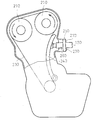
- FIG. 21 shows a state in which the tensioner 100 is mounted on the engine body 200 of the automobile.
- a pair of cam sprockets 210 and a crank sprocket 220 are arranged inside the engine body 200, and a timing chain 230 is stretched between the sprockets 210 and 220 in an endless manner.
- a chain guide 240 is swingably disposed on the moving path of the timing chain 230, and the timing chain 230 slides on the chain guide 240.
- a mounting surface 250 is formed in the engine body 200, and the tensioner 100 is inserted into a mounting hole 260 formed in the mounting surface 250 and fixed to the mounting surface 250 by a bolt 270. In this case, lubricating oil (not shown) is sealed inside the engine body 200.
- FIG. 22 shows a conventional tensioner 300 described in Patent Document 1.
- a shaft-like propelling member 310 that advances and retreats in the axial direction is inserted into the case 370.
- the propulsion member 310 is urged so as to advance from the case 370 by a propulsion spring 340 provided in the case 370.
- a holder 330 urged in the advancing direction of the propelling member 310 by a holder spring 360 is provided, and two locking pieces 320 are supported by the holder 330.
- the locking piece 320 has a shape obtained by cleaving a solid nut, and a conical cam slope 321 is formed on the outer peripheral surface on the rear side.
- a cam slope 331 is formed on the inner peripheral surface of the holder 330 so that the cam slope 321 of the locking piece 320 contacts.
- the cam slope 331 of the holder 330 is formed in a concave conical shape.
- the locking piece 320 is supported by the holder 330 in a state where the cam inclined surfaces 321 and 331 are in contact with each other.
- the propulsion member 310 is urged in the advancing direction by the propulsion spring 340.
- the locking piece 320 moves in the diameter increasing direction and the engagement between the locking teeth 323 and the locking teeth 313 of the propelling member 310 is released, so that the propelling member 310 can advance.
- the locking piece 320 is moved in the reduced diameter direction along the cam inclined surface 331 by the urging force of the pressing spring 350 and engaged with the propelling member 310. Therefore, the backward movement of the propelling member 310 is locked. By these operations, tension can be applied to the timing chain 230.
- the tensioner according to the first aspect of the present invention includes a propulsion member that is capable of moving back and forth in the axial direction inside the tubular member, a propulsion spring that urges movement of the propulsion member in the advance direction, and the tubular shape.
- a tensioner that is disposed between the tubular member and the propelling member in a state of being engaged with the locking teeth of the cylindrical member or the propelling member, and locks the propelling member in the backward direction.
- the stop piece integrally connects the load receiving portion that receives a load when the propulsion member moves backward, two or more rows of locking tooth forming portions on which the locking teeth are formed, and the locking tooth forming portions. And a connecting portion, wherein the cylindrical member and the propelling member are rotatable. That. *
- Invention of Claim 2 is the tensioner of Claim 1, Comprising: The load direction which the said load receiving part receives, and the connection direction in which the said connection part connects the said locking tooth formation part become a different direction.
- the load receiving portion and the connecting portion are provided at positions where they are not in direct contact with each other.
- Invention of Claim 3 is the tensioner of Claim 1, Comprising: The said load receiving part becomes the cone shape inclined along the propulsion direction of the said propulsion member, The said propulsion member or a cylindrical member WHEREIN: A conical support surface that is in contact with the load receiving portion is formed.
- the invention according to claim 5 is the tensioner according to claim 1, wherein the locking piece is formed by pressing a plate-like member.
- the invention according to claim 6 is the tensioner according to claim 1, further comprising a hydraulic pressure source for applying a hydraulic pressure for advancing the propulsion member.
- the locking piece is formed by the load receiving portion, the locking tooth forming portion, and the connecting portion, the locking piece can be formed by the plate-like member, and the locking piece is lightweight. be able to. For this reason, the followability with respect to the engine is good, and the processing becomes easy. Further, since the locking piece is rotatable with respect to the cylindrical member and the propelling member, when the propelling member receives a load from the engine, the locking piece can be retracted in the engaged state with the cylindrical member. Then, the propulsion member returns and can prevent overload.
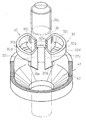
- FIG. 10 is a sectional view taken along line cc in FIG. It is a fragmentary perspective view of the tensioner of 3rd Embodiment.
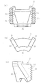
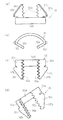
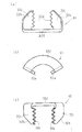
- (A), (b), (c), (d) is the front view, top view, back view, and perspective view of the locking piece used for 3rd Embodiment. It is sectional drawing in the case of manufacturing the locking piece of 3rd Embodiment.
- (A), (b), (c) is the front view, top view, and rear view which show the locking piece which is difficult to press-mold.
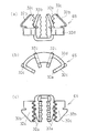
- A), (b), (c) is the front view, top view, and rear view of another latching piece which can be used for 3rd Embodiment. It is a rear view which shows another 1st shape of a locking piece.
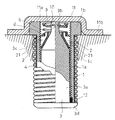
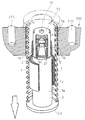
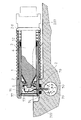
- the cylindrical member 1 is formed in a cylindrical shape in which a body portion 1a and a flange portion 1b on the rear end side (the upper end side in FIGS. 1 and 2) are connected to each other, and both end portions are opened.
- the flange portion 1b is in a state of being fixed to the engine body 200 by contacting the mounting surface 250 of the engine body 200.
- Locking teeth 1c are formed on the entire inner surface of the cylindrical member 1 including the body portion 1a and the flange portion 1b.
- the propulsion member 3 has a shaft shape including a large-diameter shaft portion 3a and a small-diameter shaft portion 3b connected to the rear end side (upper end side) of the large-diameter shaft portion 3a. Is formed.
- the propelling member 3 is entirely inserted into the cylindrical member 1 and can advance and retract in the axial direction with respect to the cylindrical member 1.
- a flange portion 3d is formed at the tip end portion (upper end portion) of the large-diameter shaft portion 3a, and the flange portion 3d contacts the chain guide 240 of the engine body 200.
- the large-diameter shaft portion 3 a of the propelling member 3 is formed to have an outer diameter slightly smaller than the inner diameter of the locking tooth 1 c on the inner surface of the cylindrical member 1. Thereby, the radial gap between the large-diameter shaft portion 3a of the propelling member 3 and the inner surface of the tubular member 1 can be reduced.
- Reference numeral 12 denotes a seal member disposed between the tip (lower end) of the cylindrical member 1 and the propelling member 3. By providing the seal member 12, the hydraulic pressure when the hydraulic pressure is applied to the cylindrical member 1 is shown. Sealability can be secured.
- the propulsion spring 4 is a coil spring.
- the propulsion spring 4 is externally inserted into the body portion 1a of the tubular member 1 in a state where the propulsion spring 4 is inserted between the flange portion 3d of the propulsion member 3 and the flange portion 1b of the tubular member 1. It is energizing to advance in the axial direction.
- the pressing spring 5 is formed by a coil spring provided between a pressing plate 9 attached to the small-diameter shaft portion 3 b of the propelling member 3 and a washer 6 disposed on the rear side (upper side) of the locking piece 2. Yes.
- the pressing spring 5 biases the locking piece 2 through the washer 6 so as to press it against the support surface 3 c of the propelling member 3.
- the locking piece 2 is pressed against the support surface 3c of the propelling member 3, and the locking piece 2 is biased so as to move in the diameter expansion direction.
- the engagement tooth 21 of the engagement piece 2 and the engagement tooth 1c of the tubular member 1 are in an engaged state in which backlash without backlash is reduced.
- the presser plate 9 is prevented from coming off from the small diameter shaft portion 3 b of the propelling member 3 by a C ring 10.
- the locking piece 2 includes a load receiving portion 22, a locking tooth forming portion 23, and a connecting portion 24.
- the locking tooth forming portion 23 has a two-row plate shape, and the two plate-shaped locking tooth forming portions 23 are integrally connected by a connecting portion 24.
- Locking teeth 21 are formed on the respective front end surfaces of the two plate-shaped locking tooth forming portions 23. As described above, the locking teeth 21 are engaged with and engaged with the locking teeth 1 c of the tubular member 1.
- the connecting portion 24 connects the locking tooth forming portion 23 in a plate shape. As described above, when the locking tooth forming portion 23 (locking tooth 21) is connected by the connecting portion 24, the structure has high torsional rigidity and improved mechanical strength.
- the propelling member 3 moves in the direction of diameter reduction along the support surface 3 c of the propelling member 3 in the advancing direction. Since the teeth 21 get over the locking teeth 1c of the cylindrical member 1, the propulsion member 3 can smoothly advance.
- the propelling member 3 moves backward, the locking piece 2 is pressed against the support surface 3c and moves in the diameter increasing direction, so that the locking tooth 21 engages with the locking tooth 1c of the tubular member 1. Thereby, the retreat of the propelling member 3 is locked.
- the locking piece 2 is rotatable with respect to the cylindrical member 1 and the propelling member 3, the locking piece 2 rotates when the propelling member 3 receives a load from the engine.
- the stop piece 2 moves backward with respect to the tubular member 1 in an engaged state with the tubular member 1. For this reason, the propelling member 3 can return and operate. Therefore, even when the engine becomes hot and the timing chain 230 is stuck, it is possible to prevent overload.
- the locking piece 2 can be reduced in weight by forming the locking piece 2 by pressing a plate-like member.
- the locking piece 2 lightweight, it is possible to improve the followability to high-frequency vibrations from the engine. And the followability with respect to the high frequency vibration from an engine becomes high, and the load of the press spring 5 which presses the locking piece 2 against the propulsion member 3 can also be reduced.
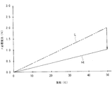
- FIG. 5 is a graph in which the vibration from the engine is plotted on the horizontal axis, and the thrust of the propelling member 3 required to follow the vibration is plotted on the vertical axis.
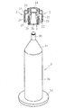
- the graph of FIG. 5 shows that the diameter of the large-diameter shaft portion 3a in the propulsion member 3 as shown in FIG. 6 is 16 mm, and the diameter of the small-diameter shaft portion 3b is 6 mm.
- a theoretical calculation was performed by constructing a tensioner to which a piece was attached and a push spring 5 was applied.
- a curved line M shows the measurement result of the locking piece 2 of this embodiment.
- the locking piece 2 As the locking piece 2, a plate material made of carbon steel and having a thickness of 1 mm was pressed to obtain an outer diameter of 16 mm, an inner diameter of 6 mm, a height of 10 mm, and a width of 8 mm.
- the locking piece 2 weighs 1.0 g.
- the curve L is the theoretical calculation result when the locking piece 2 having the same material, the same size, and the same number as the locking piece 2 of this embodiment, but having a solid structure is used.
- the locking piece on the curve L weighs 2.0 g.
- [Second Embodiment] 7 and 8 show a second embodiment of the present invention.
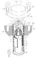
- the tensioner of this embodiment incorporates the adjustment member 14 with respect to the tensioner of 1st Embodiment, and the other structure is the same as that of 1st Embodiment.
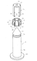
- the adjusting member 14 has a structure having a top plate portion 15 and a plurality of (four) leg portions 16 depending on the top plate portion 15.
- a non-circular operation hole 17 such as a hexagon is formed in the central portion of the top plate portion 15.
- the plurality of leg portions 16 hang from the circumference of the top plate portion 15 in four equal positions. As shown in FIG. 8, the lower end portion of each leg portion 16 has a claw portion bent inward. 18 is formed.
- the adjustment member 14 is disposed on the locking piece 2 so that the leg portion 16 enters between the four locking pieces 2.
- claw part 18 is attached to the propelling member 3 in the state of coming off prevention by engaging with the groove part 3e formed in the lower part of the support surface 3c in the propelling member 3.
- the adjustment member 14 can rotate, but the movement in the axial direction is restricted.
- Such an adjusting member 14 is attached to the propelling member 3 to allow movement of the locking piece 2 in the radial direction and movement in the axial direction, but the rotation direction of the locking piece 2 with respect to a line orthogonal to the axial direction. Regulates movements.
- the adjustment member 14 integrates the movement of the locking piece 2 in the rotation direction by the leg portion 16 entering between the locking pieces 2.
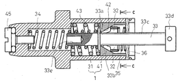
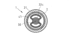
- the tensioner of this embodiment is provided with a case 31, a plurality (two) of locking pieces 32, a shaft-like propelling member 33 inserted into the case 31, and the case 31.
- the holder 41 is provided.
- the case 31 is formed in a cylindrical shape with an opening in the axial direction, and the propelling member 33 is inserted so as to be able to move forward and backward.
- a propulsion spring 34 is provided in the case 31 to urge the propulsion member 33 in the advancing direction.
- the propulsion member 33 is formed with a flange-shaped spring receiving portion 33a at an axially intermediate portion, and the urging force of the propulsion spring 34 acts on the spring receiving portion 33a.
- Locking teeth 33 c are formed on the outer peripheral surface of the propelling member 33.
- the locking teeth 33c are formed on the outer peripheral surface on the front side of the spring receiving portion 33a.
- a shoe portion 33d that contacts the chain guide 240 is provided at the front end portion of the propelling member 33, and a screw hole 33e is formed in the axial direction at the rear end portion.
- the holder 41 is formed in a short cylindrical shape, and is disposed between the spring receiving portion 33a of the propelling member 33 and the stopper plate 36 on the front end side of the case 31.
- the cylindrical case 31 and the cylindrical holder 41 correspond to the cylindrical member 1 in the first and second embodiments.
- a conical support surface 42 is formed on the inner surface of the holder 41.
- the support surface 42 is formed on the spring receiving portion 33a side, and has a conical shape in which the diameter gradually increases toward the advancing direction of the propelling member 33.
- the holder 41 is urged by a holder spring 43 so as to be movable in the advancing direction of the propelling member 33.
- the locking piece 32 is supported on the support surface 42 by being provided in the holder 41 in contact with the support surface 42 of the holder 41.
- the locking piece 32 is urged by a pressing spring 35 in a direction in contact with the support surface 42 of the holder 41.
- the locking piece 32 is formed with locking teeth 32 a that engage with the locking teeth 33 c of the propulsion member 33.
- the locking piece 32 includes a load receiving portion 32b, a locking tooth forming portion 32c, and a connecting portion 32d.
- the locking tooth forming portions 32c are formed in two rows of plates, and the locking teeth 32a described above are formed on the front end surfaces of the respective locking tooth forming portions 32c.
- the two rows of locking tooth forming portions 32c are integrally connected by a connecting portion 32d.
- the connection part 32d connects the back surface part 32e of the locking tooth formation part 32c.
- the load receiving portion 32b is formed so as to be located on the opposite side to the back surface portion 32e in the locking tooth forming portion 32c. Accordingly, the load receiving portion 32b and the connecting portion 32d are provided at positions where they are not in direct contact so that the load received by the load receiving portion 32b is different from the direction in which the connecting portion 32d connects the locking tooth forming portion 32c. Yes. Thereby, since there is no undercut part in the latching piece 32 and there is no shape restriction
- the load receiving portion 32 b is formed in a conical shape having an inclination corresponding to the support surface 42 of the holder 41.
- the screw hole 33e of the propulsion member 33 is screwed into the holding bolt 45 on the rear end side of the case 2 to place the propulsion member 33 in a standby state.
- the case 31 is assembled to the engine body 200, and the screwing between the holding bolt 45 and the screw hole 33e is released.
- the propulsion member 33 is pushed out by the propulsion spring 34 and the shoe portion 33 d comes into contact with the chain guide 240.
- the propulsion member 33 advances by the urging force of the propulsion spring 34.
- the locking piece 32 moves in the diameter increasing direction, and the locking teeth 32a are released from the engagement with the locking teeth 33c of the propulsion member 33, so that the propulsion member 33 moves forward smoothly.
- the load receiving portion 32 b moves in the diameter reducing direction along the support surface 42 of the holder 41 by the urging force of the pressing spring 35, and the locking teeth 32 a move to the propelling member 33. Engaging with the locking teeth 33c. Thereby, the backward movement of the propelling member 33 is locked.
- the propulsion member is rotated by the rotation of the locking piece 32 when the propulsion member 33 receives a load from the engine. 33 moves backward. For this reason, even when the engine becomes hot and the timing chain 230 is stuck, it is possible to prevent overload.
- the locking piece 32 can be reduced in weight by forming the locking piece 32 by pressing the plate-like member. By making the locking piece 32 lighter, it is possible to improve the followability to high-frequency vibrations from the engine. And the followability with respect to the high frequency vibration from an engine becomes high, and the load of the press spring 35 which presses the locking piece 32 to the holder 41 can also be reduced.
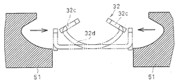
- the locking piece 32 of this embodiment is easy to press because the load receiving portion 32b and the connecting portion 32d are not in direct contact with each other.
- FIG. 13 shows this pressing process, and the locking piece 32 can be produced without generating an undercut portion by pressing the punched original plate with a pair of press dies 51.
- the connecting portion 32d connects the upper surface of the locking tooth forming portion 32c. Even in this shape, since there is no undercut portion, press working is possible, and a plate-like member can be used as a material. This makes it possible to reduce the weight and improve the function of the tensioner.
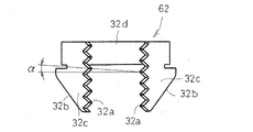
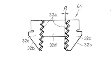
- the locking teeth 32a of the locking piece 62 in FIG. 16 are formed with the pitch ⁇ shifted.
- This locking piece 62 can be applied when the locking teeth 21 and 33c to be engaged with each other are screws having a circumferential phase, and the pitch ⁇ is shifted by the phase of the locking teeth on the other side.
- the cylindrical member 1 has both ends opened, a seal member 12 is mounted between the inner surface on the front end side and the propelling member 3, and a blind cover 73 is provided on the inner surface on the rear end side. It is mated.
- a hydraulic flow port 74 is opened, and a hydraulic pressure 71 from a hydraulic pressure source 70 provided on the engine body 200 side is filled into the tubular member 1 from the hydraulic flow port 74.
- the tubular member 1 is fixed via a bolt by a U-shaped clamp 77 in a state where the lower outer surface of the rear end portion is disposed in a shallow concave mounting groove 202 formed in the engine main body 200.
- a hydraulic circulation port 75 communicating with a hydraulic pressure source 70 provided on the engine body 200 side and a hydraulic circulation port 74 of the tubular member 1 are interposed through a seal member 79 fitted around the hydraulic circulation port 75.
- the U-shaped clamp 13 has a function of preventing the cylindrical member 1 that receives a load from the belt or chain guide 240 against which the propelling member 3 comes in contact from sliding and retreating.
- the inner wall 201 of the engine body 200 is provided with a relief portion 203 for the flange portion 3d of the propulsion member 3 and the belt or chain guide 240 along the propulsion direction of the propulsion member 3 continuously to the attachment groove 202. .
- a flat tooth having a pitch in the axial direction or a thread-like tooth having a pitch is used as the locking teeth 33c.
- a flat tooth having a pitch in the axial direction or a thread-like tooth having a pitch is used.
- the strength can be ensured
- the strength can be ensured and in the case of a screw-like tooth, the strength can be ensured and the smooth engagement can be performed.
- the number of the locking pieces 2, 32, 61, 62, 63, 64, 65 with respect to the tubular member and the propelling member can be one or three or more.
Landscapes
- Engineering & Computer Science (AREA)
- General Engineering & Computer Science (AREA)
- Mechanical Engineering (AREA)
- Devices For Conveying Motion By Means Of Endless Flexible Members (AREA)
Abstract
L'invention concerne un tensionneur présentant une excellente capacité de réaction par rapport à une vibration haute fréquence provenant d'un moteur, pour lequel le traitement d'une pièce de verrouillage peut être réalisé simplement et pour lequel il n'existe pas de restriction concernant la forme de la pièce de verrouillage. Le tensionneur est équipé des éléments suivants : un élément de propulsion (3) pouvant avancer et se rétracter dans la direction axiale à l'intérieur d'un élément tubulaire (1) ; un ressort de propulsion (4) qui sollicite le mouvement de l'élément de propulsion (3) dans la direction d'avancement ; des dents de verrouillage (1c) formées sur la surface interne de l'élément tubulaire (1) ou la surface externe de l'élément de propulsion (3) ; et une pièce de verrouillage (2) sur laquelle des dents de verrouillage (21) qui entrent en prise avec les dents de verrouillage (1c) sont formées. La pièce de verrouillage (2) est équipée des éléments suivants : une unité de réception de charge (22) qui reçoit la charge lorsque l'élément de propulsion (3) est rétracté ; au moins deux rangées de parties de formation de dents de verrouillage (23) sur lesquelles les dents de verrouillage (21) sont formées ; et des parties de liaison (24) qui raccordent d'un seul bloc les parties de formation de dents de verrouillage (23). La pièce de verrouillage peut entrer en rotation par rapport à l'élément tubulaire (1) et à l'élément de propulsion (3).
Priority Applications (2)
| Application Number | Priority Date | Filing Date | Title |
|---|---|---|---|
| PCT/JP2011/062634 WO2012164707A1 (fr) | 2011-06-01 | 2011-06-01 | Tensionneur |
| CN201180071300.3A CN103562595B (zh) | 2011-06-01 | 2011-06-01 | 张紧器 |
Applications Claiming Priority (1)
| Application Number | Priority Date | Filing Date | Title |
|---|---|---|---|
| PCT/JP2011/062634 WO2012164707A1 (fr) | 2011-06-01 | 2011-06-01 | Tensionneur |
Publications (1)
| Publication Number | Publication Date |
|---|---|
| WO2012164707A1 true WO2012164707A1 (fr) | 2012-12-06 |
Family
ID=47258592
Family Applications (1)
| Application Number | Title | Priority Date | Filing Date |
|---|---|---|---|
| PCT/JP2011/062634 Ceased WO2012164707A1 (fr) | 2011-06-01 | 2011-06-01 | Tensionneur |
Country Status (2)
| Country | Link |
|---|---|
| CN (1) | CN103562595B (fr) |
| WO (1) | WO2012164707A1 (fr) |
Cited By (2)
| Publication number | Priority date | Publication date | Assignee | Title |
|---|---|---|---|---|
| WO2016021567A1 (fr) * | 2014-08-08 | 2016-02-11 | 日本発條株式会社 | Dispositif d'application de charge |
| CN113882604A (zh) * | 2021-10-29 | 2022-01-04 | 浙江亚厦装饰股份有限公司 | 一种卡装的装配式楼梯面板安装系统及其安装方法 |
Families Citing this family (1)
| Publication number | Priority date | Publication date | Assignee | Title |
|---|---|---|---|---|
| CN108644328A (zh) * | 2018-05-28 | 2018-10-12 | 重庆隆鑫发动机有限公司 | 正时用张紧装置及发动机 |
Citations (3)
| Publication number | Priority date | Publication date | Assignee | Title |
|---|---|---|---|---|
| JPH08152051A (ja) * | 1994-09-26 | 1996-06-11 | Nhk Spring Co Ltd | 推進力付与装置 |
| JP2004190842A (ja) * | 2002-12-13 | 2004-07-08 | Tsubakimoto Chain Co | チェーン張力付与装置 |
| JP2010084878A (ja) * | 2008-10-01 | 2010-04-15 | Nhk Spring Co Ltd | テンショナー |
Family Cites Families (3)
| Publication number | Priority date | Publication date | Assignee | Title |
|---|---|---|---|---|
| CN1083956C (zh) * | 1995-12-21 | 2002-05-01 | 本田技研工业株式会社 | 推进力赋予装置 |
| JP4835915B2 (ja) * | 2005-09-30 | 2011-12-14 | 日本発條株式会社 | テンショナー |
| JP5157013B2 (ja) * | 2008-10-01 | 2013-03-06 | 日本発條株式会社 | テンショナー |
-
2011
- 2011-06-01 WO PCT/JP2011/062634 patent/WO2012164707A1/fr not_active Ceased
- 2011-06-01 CN CN201180071300.3A patent/CN103562595B/zh not_active Expired - Fee Related
Patent Citations (3)
| Publication number | Priority date | Publication date | Assignee | Title |
|---|---|---|---|---|
| JPH08152051A (ja) * | 1994-09-26 | 1996-06-11 | Nhk Spring Co Ltd | 推進力付与装置 |
| JP2004190842A (ja) * | 2002-12-13 | 2004-07-08 | Tsubakimoto Chain Co | チェーン張力付与装置 |
| JP2010084878A (ja) * | 2008-10-01 | 2010-04-15 | Nhk Spring Co Ltd | テンショナー |
Cited By (2)
| Publication number | Priority date | Publication date | Assignee | Title |
|---|---|---|---|---|
| WO2016021567A1 (fr) * | 2014-08-08 | 2016-02-11 | 日本発條株式会社 | Dispositif d'application de charge |
| CN113882604A (zh) * | 2021-10-29 | 2022-01-04 | 浙江亚厦装饰股份有限公司 | 一种卡装的装配式楼梯面板安装系统及其安装方法 |
Also Published As
| Publication number | Publication date |
|---|---|
| CN103562595B (zh) | 2016-07-06 |
| CN103562595A (zh) | 2014-02-05 |
Similar Documents
| Publication | Publication Date | Title |
|---|---|---|
| FR3026454A1 (fr) | Mecanisme de vis a rouleaux et procede de fabrication associe | |
| RU2514319C2 (ru) | Усовершенствованное прессовое соединение корпуса зубчатой рейки | |
| JP5157013B2 (ja) | テンショナー | |
| EP2315967B1 (fr) | Tensionneur de type pince | |
| JP5364930B2 (ja) | テンショナー | |
| CN1190296C (zh) | 滚珠丝杠及使用它的直线运动装置 | |
| JP5897410B2 (ja) | テンショナ | |
| CN103562595B (zh) | 张紧器 | |
| CN105598500B (zh) | 一种深孔镗削加工方法 | |
| CN112045579B (zh) | 用于对物体进行夹紧的夹紧装置 | |
| JP2007057026A (ja) | 回転−直線運動変換装置及びその組付け方法 | |
| WO2016021566A1 (fr) | Dispositif d'application de charge | |
| JP4680736B2 (ja) | テンショナリフタ | |
| JP4927377B2 (ja) | オートテンショナ | |
| JP5250889B2 (ja) | テンショナー | |
| CN104145138A (zh) | 行星滚子螺纹传动装置和用于制造行星滚子螺纹传动装置的方法 | |
| JP3201198U (ja) | テレスコピック接合部構造 | |
| JP6317331B2 (ja) | テンショナー | |
| CN105665763B (zh) | 一种深孔镗削机械臂切削段结构 | |
| JP4903403B2 (ja) | オートテンショナ | |
| JP5381587B2 (ja) | 工作機械のタレット装置 | |
| RU80525U1 (ru) | Роликовинтовая передача | |
| JP2009216212A (ja) | チェーンテンショナ | |
| WO2022118593A1 (fr) | Réducteur à engrenage planétaire | |
| JP2007100784A (ja) | オートテンショナ |
Legal Events
| Date | Code | Title | Description |
|---|---|---|---|
| 121 | Ep: the epo has been informed by wipo that ep was designated in this application |
Ref document number: 11866505 Country of ref document: EP Kind code of ref document: A1 |
|
| NENP | Non-entry into the national phase |
Ref country code: DE |
|
| 122 | Ep: pct application non-entry in european phase |
Ref document number: 11866505 Country of ref document: EP Kind code of ref document: A1 |
|
| NENP | Non-entry into the national phase |
Ref country code: JP |