WO2012164723A1 - Procédé de formation d'une cellule entièrement à semi-conducteurs - Google Patents
Procédé de formation d'une cellule entièrement à semi-conducteurs Download PDFInfo
- Publication number
- WO2012164723A1 WO2012164723A1 PCT/JP2011/062713 JP2011062713W WO2012164723A1 WO 2012164723 A1 WO2012164723 A1 WO 2012164723A1 JP 2011062713 W JP2011062713 W JP 2011062713W WO 2012164723 A1 WO2012164723 A1 WO 2012164723A1
- Authority
- WO
- WIPO (PCT)
- Prior art keywords
- active material
- electrode active
- material layer
- positive electrode
- battery
- Prior art date
- Legal status (The legal status is an assumption and is not a legal conclusion. Google has not performed a legal analysis and makes no representation as to the accuracy of the status listed.)
- Ceased
Links
Images
Classifications
-
- H—ELECTRICITY
- H01—ELECTRIC ELEMENTS
- H01M—PROCESSES OR MEANS, e.g. BATTERIES, FOR THE DIRECT CONVERSION OF CHEMICAL ENERGY INTO ELECTRICAL ENERGY
- H01M10/00—Secondary cells; Manufacture thereof
- H01M10/04—Construction or manufacture in general
- H01M10/0468—Compression means for stacks of electrodes and separators
-
- H—ELECTRICITY
- H01—ELECTRIC ELEMENTS
- H01M—PROCESSES OR MEANS, e.g. BATTERIES, FOR THE DIRECT CONVERSION OF CHEMICAL ENERGY INTO ELECTRICAL ENERGY
- H01M10/00—Secondary cells; Manufacture thereof
- H01M10/04—Construction or manufacture in general
- H01M10/0486—Frames for plates or membranes
-
- H—ELECTRICITY
- H01—ELECTRIC ELEMENTS
- H01M—PROCESSES OR MEANS, e.g. BATTERIES, FOR THE DIRECT CONVERSION OF CHEMICAL ENERGY INTO ELECTRICAL ENERGY
- H01M10/00—Secondary cells; Manufacture thereof
- H01M10/05—Accumulators with non-aqueous electrolyte
- H01M10/056—Accumulators with non-aqueous electrolyte characterised by the materials used as electrolytes, e.g. mixed inorganic/organic electrolytes
- H01M10/0561—Accumulators with non-aqueous electrolyte characterised by the materials used as electrolytes, e.g. mixed inorganic/organic electrolytes the electrolyte being constituted of inorganic materials only
- H01M10/0562—Solid materials
-
- H—ELECTRICITY
- H01—ELECTRIC ELEMENTS
- H01M—PROCESSES OR MEANS, e.g. BATTERIES, FOR THE DIRECT CONVERSION OF CHEMICAL ENERGY INTO ELECTRICAL ENERGY
- H01M10/00—Secondary cells; Manufacture thereof
- H01M10/05—Accumulators with non-aqueous electrolyte
- H01M10/058—Construction or manufacture
-
- H—ELECTRICITY
- H01—ELECTRIC ELEMENTS
- H01M—PROCESSES OR MEANS, e.g. BATTERIES, FOR THE DIRECT CONVERSION OF CHEMICAL ENERGY INTO ELECTRICAL ENERGY
- H01M10/00—Secondary cells; Manufacture thereof
- H01M10/05—Accumulators with non-aqueous electrolyte
- H01M10/058—Construction or manufacture
- H01M10/0583—Construction or manufacture of accumulators with folded construction elements except wound ones, i.e. folded positive or negative electrodes or separators, e.g. with "Z"-shaped electrodes or separators
-
- H—ELECTRICITY
- H01—ELECTRIC ELEMENTS
- H01M—PROCESSES OR MEANS, e.g. BATTERIES, FOR THE DIRECT CONVERSION OF CHEMICAL ENERGY INTO ELECTRICAL ENERGY
- H01M10/00—Secondary cells; Manufacture thereof
- H01M10/05—Accumulators with non-aqueous electrolyte
- H01M10/058—Construction or manufacture
- H01M10/0585—Construction or manufacture of accumulators having only flat construction elements, i.e. flat positive electrodes, flat negative electrodes and flat separators
-
- H—ELECTRICITY
- H01—ELECTRIC ELEMENTS
- H01M—PROCESSES OR MEANS, e.g. BATTERIES, FOR THE DIRECT CONVERSION OF CHEMICAL ENERGY INTO ELECTRICAL ENERGY
- H01M50/00—Constructional details or processes of manufacture of the non-active parts of electrochemical cells other than fuel cells, e.g. hybrid cells
- H01M50/40—Separators; Membranes; Diaphragms; Spacing elements inside cells
- H01M50/46—Separators, membranes or diaphragms characterised by their combination with electrodes
-
- H—ELECTRICITY
- H01—ELECTRIC ELEMENTS
- H01M—PROCESSES OR MEANS, e.g. BATTERIES, FOR THE DIRECT CONVERSION OF CHEMICAL ENERGY INTO ELECTRICAL ENERGY
- H01M10/00—Secondary cells; Manufacture thereof
- H01M10/04—Construction or manufacture in general
- H01M10/045—Cells or batteries with folded plate-like electrodes
-
- H—ELECTRICITY
- H01—ELECTRIC ELEMENTS
- H01M—PROCESSES OR MEANS, e.g. BATTERIES, FOR THE DIRECT CONVERSION OF CHEMICAL ENERGY INTO ELECTRICAL ENERGY
- H01M10/00—Secondary cells; Manufacture thereof
- H01M10/05—Accumulators with non-aqueous electrolyte
- H01M10/052—Li-accumulators
-
- H—ELECTRICITY
- H01—ELECTRIC ELEMENTS
- H01M—PROCESSES OR MEANS, e.g. BATTERIES, FOR THE DIRECT CONVERSION OF CHEMICAL ENERGY INTO ELECTRICAL ENERGY
- H01M4/00—Electrodes
- H01M4/02—Electrodes composed of, or comprising, active material
- H01M4/04—Processes of manufacture in general
- H01M4/043—Processes of manufacture in general involving compressing or compaction
-
- H—ELECTRICITY
- H01—ELECTRIC ELEMENTS
- H01M—PROCESSES OR MEANS, e.g. BATTERIES, FOR THE DIRECT CONVERSION OF CHEMICAL ENERGY INTO ELECTRICAL ENERGY
- H01M6/00—Primary cells; Manufacture thereof
- H01M6/42—Grouping of primary cells into batteries
- H01M6/46—Grouping of primary cells into batteries of flat cells
-
- Y—GENERAL TAGGING OF NEW TECHNOLOGICAL DEVELOPMENTS; GENERAL TAGGING OF CROSS-SECTIONAL TECHNOLOGIES SPANNING OVER SEVERAL SECTIONS OF THE IPC; TECHNICAL SUBJECTS COVERED BY FORMER USPC CROSS-REFERENCE ART COLLECTIONS [XRACs] AND DIGESTS
- Y02—TECHNOLOGIES OR APPLICATIONS FOR MITIGATION OR ADAPTATION AGAINST CLIMATE CHANGE
- Y02E—REDUCTION OF GREENHOUSE GAS [GHG] EMISSIONS, RELATED TO ENERGY GENERATION, TRANSMISSION OR DISTRIBUTION
- Y02E60/00—Enabling technologies; Technologies with a potential or indirect contribution to GHG emissions mitigation
- Y02E60/10—Energy storage using batteries
-
- Y—GENERAL TAGGING OF NEW TECHNOLOGICAL DEVELOPMENTS; GENERAL TAGGING OF CROSS-SECTIONAL TECHNOLOGIES SPANNING OVER SEVERAL SECTIONS OF THE IPC; TECHNICAL SUBJECTS COVERED BY FORMER USPC CROSS-REFERENCE ART COLLECTIONS [XRACs] AND DIGESTS
- Y02—TECHNOLOGIES OR APPLICATIONS FOR MITIGATION OR ADAPTATION AGAINST CLIMATE CHANGE
- Y02P—CLIMATE CHANGE MITIGATION TECHNOLOGIES IN THE PRODUCTION OR PROCESSING OF GOODS
- Y02P70/00—Climate change mitigation technologies in the production process for final industrial or consumer products
- Y02P70/50—Manufacturing or production processes characterised by the final manufactured product
-
- Y—GENERAL TAGGING OF NEW TECHNOLOGICAL DEVELOPMENTS; GENERAL TAGGING OF CROSS-SECTIONAL TECHNOLOGIES SPANNING OVER SEVERAL SECTIONS OF THE IPC; TECHNICAL SUBJECTS COVERED BY FORMER USPC CROSS-REFERENCE ART COLLECTIONS [XRACs] AND DIGESTS
- Y10—TECHNICAL SUBJECTS COVERED BY FORMER USPC
- Y10T—TECHNICAL SUBJECTS COVERED BY FORMER US CLASSIFICATION
- Y10T29/00—Metal working
- Y10T29/49—Method of mechanical manufacture
- Y10T29/49002—Electrical device making
- Y10T29/49108—Electric battery cell making
- Y10T29/49114—Electric battery cell making including adhesively bonding
Definitions
- the present invention relates to a method for producing an all-solid battery having excellent adhesion between an electrode active material layer and a solid electrolyte layer.
- lithium secondary batteries have high electromotive force and high energy density, they are widely used in the fields of information-related equipment and communication equipment.
- development of electric vehicles and hybrid vehicles has been urgently caused by environmental problems and resource problems, and lithium secondary batteries are also being studied as power sources for these.
- lithium secondary batteries currently on the market use an electrolyte containing a flammable organic solvent, they are equipped with a safety device that prevents the temperature rise during short-circuiting and in terms of structure and materials for short-circuit prevention. Improvement is needed.
- an all-solid lithium secondary battery in which the electrolyte solution is changed to a solid electrolyte layer to make the battery all solid does not use a flammable organic solvent in the battery, so the safety device can be simplified and manufactured. It is considered to be excellent in cost and productivity.
- Patent Documents 1 to 3 disclose cold isostatic pressing (CIP) and the like as a method for forming a solid electrolyte layer.
- Patent Document 4 discloses a battery including an electrode base material that is partitioned into a plurality of regions and folded for each region.
- JP 2008-112661 A JP 2010-108809 A JP 2010-108802 A JP 2010-067443
- the present invention has been made in view of the above problems, and has as its main object to provide a method for producing an all-solid battery excellent in adhesion between an electrode active material layer and a solid electrolyte layer.
- a power generation element having a positive electrode active material layer, a negative electrode active material layer, and a solid electrolyte layer formed between the positive electrode active material layer and the negative electrode active material layer.
- An object of the present invention is to provide a method for producing an all-solid-state battery, comprising a pressing step of applying isotropic pressure to an object to be pressed.
- an all-solid battery having excellent adhesion between the electrode active material layer and the solid electrolyte layer can be obtained by applying isotropic pressure to the power generation element.
- the isotropic pressure pressurization is pressurization by a hydraulic pressure. This is because the power generation element can be more effectively pressurized.
- the member to be pressurized is a battery element having the power generation element and a positive electrode current collector and a negative electrode current collector that collect current of the power generation element sealed with an outer package. It is preferable. This is because cracking and peeling of the electrode active material layer can be effectively prevented by applying isotropic pressure after sealing the battery element with the exterior body.
- the isotropic pressure is preferably in the range of 200 MPa to 1000 MPa.
- the pressed body has an elastic body. This is because, by using the elastic body, minute deformation of the pressed body can be prevented and warpage can be prevented.
- the pressurized body is obtained by further sealing the exterior body in which the battery element is sealed with a protective body, and the pressure between the exterior body and the protective body is changed to the exterior body. It is preferable to make it higher than the pressure inside the body. This is because the power generation element can be more effectively pressurized.
- the member to be pressurized includes a battery element having the power generation element, and a positive electrode current collector and a negative electrode current collector that collect current of the power generation element, and the battery element includes a plurality of
- the power generation element is provided between the positive electrode current collector and the negative electrode current collector, and an insulating layer is provided between the adjacent power generation elements, and the pressed body is positioned at the position of the insulating layer. It is preferable to bend with. It is because it can arrange
- An all-solid battery manufacturing method of the present invention includes a positive electrode active material layer, a negative electrode active material layer, and a power generation element including a solid electrolyte layer formed between the positive electrode active material layer and the negative electrode active material layer.
- the pressurizing body includes a pressurizing step for applying isotropic pressure.
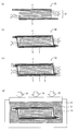
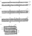
- FIG. 1 is a schematic cross-sectional view showing an example of a method for producing an all solid state battery of the present invention.
- a power generation element 10 having a positive electrode active material layer 1, a negative electrode active material layer 2, and a solid electrolyte layer 3 formed between the positive electrode active material layer 1 and the negative electrode active material layer 2,
- a battery element 11 having a positive electrode current collector 4 and a negative electrode current collector 5 for collecting current of the element 3 is prepared (FIG. 1A).
- the power generation element 10 is a so-called bipolar power generation element and includes an interlayer current collector 6.
- the positive electrode current collector 4 and the negative electrode current collector 5 are formed on the surfaces of the positive electrode active material layer 1 and the negative electrode active material layer 2 that are located on the outermost sides of the power generation element 10, respectively.
- the battery element 11 is sealed with the exterior body 7 to obtain the battery element-containing exterior body 12 (FIG. 1B).
- the battery element-containing exterior body 12 is further sealed with the protector 8 to obtain the exterior body-containing protector 13 (FIG. 1C).
- the exterior body-containing protective body 13 becomes a pressed body.
- the protector 8 is a film having water resistance and insulation, for example.
- the outer body-containing protective body 13 is placed in a pressure-resistant container (for example, an iron container) 22 filled with a liquid (for example, water) 21, and a pressure 23 is applied (FIG. 1 (d)).
- the all-solid battery is obtained by peeling off the protector 8.
- the all solid state battery obtained by the present invention refers to a member having at least a power generation element.
- an all-solid battery having excellent adhesion between the electrode active material layer and the solid electrolyte layer can be obtained by applying isotropic pressure to the power generation element.
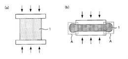
- the conventional flat press and roll press have the following problems. That is, since the surface of the electrode active material layer or the solid electrolyte layer has minute unevenness (for example, unevenness of several ⁇ m), the anisotropic pressurization such as flat press or roll press causes pressure on the protrusion. It becomes higher and the pressure tends to be lower in the recess. As a result, the surface cannot be uniformly pressed, and it becomes difficult to sufficiently improve the adhesion between the electrode active material layer and the solid electrolyte layer.
- the electrode active material layer and the solid electrolyte layer are obtained by fixing powders such as the active material and the solid electrolyte material. Therefore, when the filling rate is increased by compression, there is a characteristic that the layer becomes hard (becomes brittle). For example, as shown in FIG. 2A, when the positive electrode active material layer 1 is pressurized from above and below, as shown in FIG. In the rolling deformation portion A, the positive electrode active material layer 1 has a characteristic of becoming hard (brittle).
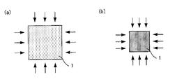
- the positive electrode active material layer 1 can be pressurized with a uniform pressure from all directions using, for example, water pressure.
- production of the above rolling deformation parts can be prevented. Therefore, even if the applied pressure is set higher, cracking of the electrode active material layer or the solid electrolyte layer, separation between the electrode active material layer and the solid electrolyte layer, separation between the electrode active material layer and the current collector, etc. There is an advantage that is difficult to occur. Further, by setting the applied pressure higher, the filling rate of each layer can be improved, and an all solid state battery with good battery performance (capacity and output) can be obtained.
- Patent Documents 1 to 3 disclose cold isostatic pressing (CIP) and the like as a method for forming a solid electrolyte layer.
- CIP cold isostatic pressing
- these techniques are intended to form a solid electrolyte layer from these members for the same type of solid electrolyte particles or the same type of solid electrolyte sheet.
- Patent Documents 1 to 3 disclose electrode active material layers.
- the adhesiveness of an electrode active material layer and a solid electrolyte layer can fully be improved by performing isotropic pressure pressurization to a power generation element with respect to the whole power generation element.
- the pressurizing step in the present invention is a step of applying isotropic pressure to a member to be pressed including a power generation element.
- the pressed body in the present invention includes at least a power generation element having a positive electrode active material layer, a negative electrode active material layer, and a solid electrolyte layer formed between the positive electrode active material layer and the negative electrode active material layer.
- Specific examples of the object to be pressed include (i) a power generation element, (ii) a battery element having a power generation element, a positive electrode current collector and a negative electrode current collector, and (iii) a battery element in which the battery element is sealed with an outer package. A containing exterior body etc. can be mentioned.
- Each of the members (i) to (iii) may be sealed with a protective body for protecting from an isotropic pressure pressurizing medium.
- the power generation element in the present invention includes a positive electrode active material layer, a negative electrode active material layer, and a solid electrolyte layer formed between the positive electrode active material layer and the negative electrode active material layer.
- the positive electrode active material layer in the present invention is a layer containing at least a positive electrode active material, and further contains at least one of a solid electrolyte material, a conductive material and a binder as necessary. You may do it. Although it does not specifically limit as a positive electrode active material, An oxide active material and a sulfide active material can be mentioned. Examples of the oxide active material used as the positive electrode active material of the all-solid-state lithium battery include rock salt layers such as LiCoO 2 , LiMnO 2 , LiNiO 2 , LiVO 2 , and LiNi 1/3 Co 1/3 Mn 1/3 O 2.
- Type active materials spinel type active materials such as LiMn 2 O 4 and Li (Ni 0.5 Mn 1.5 ) O 4 , olivine type active materials such as LiFePO 4 and LiMnPO 4 , Li 2 FeSiO 4 , Li 2 MnSiO 4 Examples thereof include Si-containing active materials. It is preferable that a coat layer for suppressing reaction with the sulfide solid electrolyte material is formed on the surface of the oxide active material. This is because the generation of the high resistance layer due to the reaction between the oxide active material and the sulfide solid electrolyte material can be suppressed. Examples of the material for the coating layer include oxide materials having ion conductivity, and specific examples include lithium niobate. Further, examples of the sulfide active material used as the positive electrode active material of the all solid lithium battery include copper subrel, iron sulfide, cobalt sulfide, nickel sulfide and the like.
- Examples of the shape of the positive electrode active material include a particle shape.
- the average particle diameter (D 50 ) of the positive electrode active material is preferably in the range of 0.1 ⁇ m to 50 ⁇ m, for example.
- the average particle size can be determined by a particle size distribution meter.
- the content of the positive electrode active material in the positive electrode active material layer is preferably in the range of 10 wt% to 99 wt%, for example, and more preferably in the range of 20 wt% to 90 wt%.
- the positive electrode active material layer preferably further contains a solid electrolyte material. This is because the ion conductivity in the positive electrode active material layer can be improved.
- the solid electrolyte material contained in the positive electrode active material layer is the same as the solid electrolyte material described later in “(iii) Solid electrolyte layer”.
- the content of the solid electrolyte material in the positive electrode active material layer is, for example, preferably in the range of 1% by weight to 90% by weight, and more preferably in the range of 10% by weight to 80% by weight.
- the positive electrode active material layer may further contain a conductive material.
- a conductive material By adding a conductive material, the electronic conductivity of the positive electrode active material layer can be improved.
- the conductive material include acetylene black, ketjen black, and carbon fiber.
- the positive electrode active material layer may further contain a binder. Examples of the binder include fluorine-containing binders such as PTFE and PVDF.
- the thickness of the positive electrode active material layer varies depending on the type of the target battery, but is preferably in the range of 0.1 ⁇ m to 1000 ⁇ m, for example.
- the negative electrode active material layer in the present invention is a layer containing at least a negative electrode active material, and further contains at least one of a solid electrolyte material, a conductive material and a binder as necessary. You may do it.
- a negative electrode active material For example, a carbon active material, a metal active material, an oxide active material etc. can be mentioned.
- the carbon active material include graphite such as mesocarbon microbeads (MCMB) and highly oriented graphite (HOPG), and amorphous carbon such as hard carbon and soft carbon.
- the metal active material include In, Al, Si, and Sn.
- oxide active material may include, for example Nb 2 O 5, Li 4 Ti 5 O 12, SiO and the like.
- the shape of the negative electrode active material examples include a particle shape and a film shape.
- the average particle diameter (D 50 ) of the negative electrode active material is preferably in the range of 0.1 ⁇ m to 50 ⁇ m, for example.
- the average particle size can be determined by a particle size distribution meter.
- the content of the negative electrode active material in the negative electrode active material layer is preferably in the range of, for example, 10% by weight to 99% by weight, and more preferably in the range of 20% by weight to 90% by weight.
- the negative electrode active material layer preferably further contains a solid electrolyte material. This is because the ion conductivity in the negative electrode active material layer can be improved.
- the solid electrolyte material contained in the negative electrode active material layer is the same as the solid electrolyte material described in “(iii) Solid electrolyte layer” described later.
- the content of the solid electrolyte material in the negative electrode active material layer is, for example, preferably in the range of 1% by weight to 90% by weight, and more preferably in the range of 10% by weight to 80% by weight.
- the negative electrode active material layer may further contain a conductive material.
- the negative electrode active material layer may further contain a binder. Since the conductive material and the binder are the same as those described in the above-mentioned “(i) Positive electrode active material layer”, description thereof is omitted here.
- the thickness of the negative electrode active material layer varies depending on the type of the target battery, but is preferably in the range of 0.1 ⁇ m to 1000 ⁇ m, for example.
- the solid electrolyte layer in the present invention is a layer containing a solid electrolyte material.
- the solid electrolyte material include a sulfide solid electrolyte material and an oxide solid electrolyte material.
- the sulfide solid electrolyte material is preferable in that it has a higher ion conductivity than the oxide solid electrolyte material, and the oxide solid electrolyte material has higher chemical stability than the sulfide solid electrolyte material. This is preferable.
- Examples of the oxide solid electrolyte material used in the all solid lithium battery include a compound having a NASICON type structure.
- a compound having a NASICON type structure a compound represented by the general formula Li 1 + x Al x Ge 2-x (PO 4 ) 3 (0 ⁇ x ⁇ 2) can be given.
- the compound, Li 1.5 Al 0.5 Ge 1.5 ( PO 4) is preferably 3.
- Another example of the compound having a NASICON type structure is a compound represented by the general formula Li 1 + x Al x Ti 2-x (PO 4 ) 3 (0 ⁇ x ⁇ 2).
- the compound, Li 1.5 Al 0.5 Ti 1.5 ( PO 4) is preferably 3.
- oxide solid electrolyte material used for the all-solid lithium secondary battery examples include LiLaTiO (for example, Li 0.34 La 0.51 TiO 3 ), LiPON (for example, Li 2.9 PO 3). 3 N 0.46 ), LiLaZrO (for example, Li 7 La 3 Zr 2 O 12 ) and the like.
- Examples of the sulfide solid electrolyte material used for the all solid lithium battery include Li 2 S—P 2 S 5 , Li 2 S—P 2 S 5 —LiI, Li 2 S—P 2 S 5 —Li 2 O, Li 2 S—P 2 S 5 —Li 2 O—LiI, Li 2 S—SiS 2 , Li 2 S—SiS 2 —LiI, Li 2 S—SiS 2 —LiBr, Li 2 S—SiS 2 —LiCl, Li 2 S-SiS 2 -B 2 S 3 -LiI, Li 2 S-SiS 2 -P 2 S 5 -LiI, Li 2 S-B 2 S 3, Li 2 S-P 2 S 5 -Z m S n ( However, m and n are positive numbers, Z is any one of Ge, Zn, and Ga.), Li 2 S—GeS 2 , Li 2 S—SiS 2 —Li 3 PO 4 , Li 2 S
- Li 2 S—P 2 S 5 means a sulfide solid electrolyte material using a raw material composition containing Li 2 S and P 2 S 5, and the same applies to other descriptions. is there. Further, the sulfide solid electrolyte material may be sulfide glass or crystallized sulfide glass.
- the content of the solid electrolyte material in the solid electrolyte layer is, for example, preferably 60% by weight or more, more preferably 70% by weight or more, and particularly preferably 80% by weight or more.
- the solid electrolyte layer may contain a binder or may be composed only of a solid electrolyte material.
- the thickness of the solid electrolyte layer varies greatly depending on the configuration of the battery. For example, the thickness is preferably in the range of 0.1 ⁇ m to 1000 ⁇ m, and more preferably in the range of 0.1 ⁇ m to 300 ⁇ m.
- the power generation element in the present invention is not particularly limited as long as it has a positive electrode active material layer, a negative electrode active material layer, and a solid electrolyte layer. Further, the power generation element may be a monopolar power generation element or a bipolar power generation element.
- the battery element in this invention has a power generation element, and the positive electrode current collector and negative electrode current collector which collect current of the said power generation element.
- the material for the positive electrode current collector include SUS, aluminum, nickel, iron, titanium, and carbon.
- the material for the negative electrode current collector include SUS, copper, nickel, and carbon.
- the thicknesses of the positive electrode current collector and the negative electrode current collector are not particularly limited as long as they are thick enough to apply isotropic pressure to the power generation element.
- the battery element in the present invention may be a monopolar battery element or a bipolar battery element.
- FIG. 4 is a schematic cross-sectional view illustrating a battery element in the present invention.
- FIG. 4A shows a monopolar battery element.
- the battery element includes a power generation element 10 having one unit of a positive electrode active material layer 1, a negative electrode active material layer 2, and a solid electrolyte layer 3, and a positive electrode active material layer 1.
- a positive electrode current collector 4 that collects current
- a negative electrode current collector 5 that collects current of the negative electrode active material layer 2.
- FIG. 4B shows a laminated monopolar battery element, which includes a power generation element 10 having three units of a positive electrode active material layer 1, a negative electrode active material layer 2, and a solid electrolyte layer 3, and a positive electrode active element.
- a positive electrode current collector 4 that collects current of the material layer 1 and a negative electrode current collector 5 that collects current of the negative electrode active material layer 2 are included.
- at least one of the positive electrode current collector and the negative electrode current collector is arranged as an interlayer current collector.
- the number of units composed of the positive electrode active material layer 1, the negative electrode active material layer 2 and the solid electrolyte layer 3 is not particularly limited. It is preferably within the range, and more preferably within the range of 2 to 20.
- FIG. 4C shows a bipolar battery element.
- the battery element includes a power generation element 10 having three units of a positive electrode active material layer 1, a negative electrode active material layer 2, and a solid electrolyte layer 3, and between each unit. It has a formed interlayer current collector 6, a positive electrode current collector 4 that collects current from the positive electrode active material layer 1, and a negative electrode current collector 5 that collects current from the negative electrode active material layer 2.
- the number of stacked units composed of the positive electrode active material layer 1, the negative electrode active material layer 2 and the solid electrolyte layer 3 is not particularly limited, but for example within the range of 2 to 60 Preferably, it is preferably in the range of 2-20.
- the material for the interlayer current collector is not particularly limited, and the same materials as those described for the positive electrode current collector and the negative electrode current collector described above can be used.
- the method for producing a battery element in the present invention is not particularly limited, and a method similar to a general battery element can be used.
- a battery element manufacturing method a positive electrode active material layer forming slurry is applied on a positive electrode current collector and dried to form a positive electrode active material layer, and a solid electrolyte layer is formed on the positive electrode active material layer.
- a solid electrolyte layer is formed by applying and drying the forming slurry, and a negative electrode active material layer is formed by applying and drying the negative electrode active material layer forming slurry on the solid electrolyte layer.
- the negative electrode A method of disposing a negative electrode current collector on the active material layer can be given.
- a positive electrode active material layer, a solid electrolyte layer, and a negative electrode active material layer pellet are respectively produced, and these pellets are sandwiched between a positive electrode current collector and a negative electrode current collector.
- a method can be mentioned.
- the battery element containing exterior body in this invention seals the battery element mentioned above with the exterior body.
- the exterior body is not particularly limited as long as the battery element can be sealed, and examples thereof include a laminate sheet in which a metal base is coated with a resin.
- the material for the metal substrate include aluminum.
- a polyethylene terephthalate etc. can be mentioned, for example.
- Examples of the method for sealing the battery element with the exterior body include a method in which the battery element is disposed inside the exterior body and the exterior body is sealed by thermal welding under reduced pressure.
- examples of the pressurized body include a power generation element, a battery element, a battery element-containing exterior body, and the like.
- each of these members may be sealed with a protective body for protecting from an isotropic pressure pressurizing medium.
- the protector protects the member to be pressed from a liquid such as water.
- a protector has insulation. This is because a short circuit of the power generation element can be prevented.
- the material of the protector include resin, rubber, metal (aluminum, etc.) and the like.
- the shape of a protector is not specifically limited, For example, a film form etc. can be mentioned.
- the method of sealing a protector by heat-sealing under reduced pressure can be mentioned, for example.
- the all-solid-state battery manufacturing method of the present invention is characterized in that isotropic pressure is applied to an object to be pressed.
- isotropic pressure pressurization include pressurization by liquid pressure and pressurization by gas pressure.
- Pressurization by liquid pressure has the advantage that a high pressure of several hundred MPa can be applied isotropically
- pressurization by gas pressure has the advantage that pressure can be applied isotropically under high temperature conditions.
- a typical example of the pressurization by liquid pressure is cold isostatic pressurization (CIP).
- CIP cold isostatic pressurization
- the liquid becomes a pressure medium.
- the liquid include water. The liquid may be in a normal temperature state or in a heated state.
- pressurization by gas pressure examples include hot isostatic pressurization (HIP).
- HIP hot isostatic pressurization
- gas serves as a pressure medium.
- the gas include argon gas.
- the said gas may be a normal temperature state and may be a heating state.
- the heating temperature of gas is 120 degrees C or less, for example, and it is more preferable that it is 80 degrees C or less.
- the pressure of the isotropic pressure is not particularly limited as long as the desired adhesion can be obtained.
- the pressure is preferably 200 MPa or more, and more preferably 300 MPa or more. This is because if the pressure is too low, the adhesion between the electrode active material layer and the solid electrolyte layer may not be sufficiently improved.
- the pressure is preferably 1000 MPa or less, more preferably 800 MPa or less, and even more preferably 500 MPa or less. This is because if the pressure is too high, an internal short circuit may occur or the equipment cost may increase.
- the isotropic pressure pressurization time varies depending on the type of isotropic pressure pressurization, but is preferably in the range of, for example, 5 minutes to 60 minutes, and is preferably in the range of 10 minutes to 30 minutes. It is more preferable.
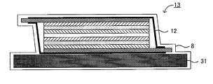
- the member to be pressed has an elastic body. This is because, by using the elastic body, minute deformation of the pressed body can be prevented and warpage can be prevented.
- the exterior body-containing protective body 13 that is a pressed body has an elastic body 31.
- the battery element-containing exterior body 12 and the elastic body 31 are sealed inside the exterior body-containing protective body 13 by the protector 8. Thereby, it is possible to prevent a pressure medium (for example, water) from entering the exterior body-containing protective body 13 during isotropic pressure application.
- a pressure medium for example, water
- the position where the elastic body is arranged is not particularly limited as long as it can prevent the occurrence of warping, and may be arranged so as to be included in the pressurized body. It may be arranged so as to be exposed to the outside.
- the material of the elastic body include resin, rubber, metal (aluminum, etc.), and rubber is preferable. Further, considering that the elastic body itself can be a factor of deformation, it is preferable that the elastic body is hard while having elasticity. Therefore, for example, the rubber is more preferably hard rubber.
- the thickness of the elastic body varies depending on the material of the elastic body, but is preferably in the range of 1 mm to 20 mm, for example, and more preferably in the range of 3 mm to 10 mm.
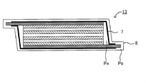
- the body to be pressurized is the outer body in which the battery element is sealed, further sealed with a protective body, and the pressure between the outer body and the protective body It is preferable to make it higher than the pressure.
- the pressurized body is an exterior body-containing protection body 13 in which the exterior body 7 in which the battery element is sealed is further sealed with a protection body 8.
- the pressure P B between is preferably higher than the pressure P a of the inside of the exterior body 7.
- P A is the gauge pressure (relative pressure), for example, it is preferably in the range of -100 kPa ⁇ -80 kPa, and more preferably in the range of -100 kPa ⁇ -90 kPa.
- P B is a gauge pressure (relative pressure), for example, preferably within a range of ⁇ 80 kPa to ⁇ 60 kPa, and more preferably within a range of ⁇ 80 kPa to ⁇ 70 kPa.
- P B -P A is, for example, preferably 10 kPa or more, and more preferably in the range of 10 kPa to 20 kPa.
- the battery element is sealed with an exterior body so as to cover the terminal portion of the battery element, and after the isotropic pressure is applied, a part of the exterior body is cut out, and the terminal portion Is preferably exposed.
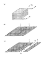
- the terminal portion is sealed with the exterior body so as to cover the terminal portion 16 of the battery element 11. In this state, isotropic pressure is applied, and then, as shown in FIG. 7C, a part of the outer package 7 is cut out to expose the terminal portion 16.
- the terminal portion 16 may be protected with a protective tape (peeling tape), or the exterior body 7 may be cut in advance.
- the member to be pressurized has a battery element having a power generation element, a positive electrode current collector that collects current of the power generation element, and a negative electrode current collector, and the battery element includes a plurality of power generation elements.
- the battery element includes a plurality of power generation elements.
- an insulating layer is preferably provided between adjacent power generation elements.
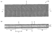
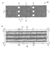
- FIG. 8 is a schematic view showing an example of the battery element in the present invention.
- FIG. 8A is a schematic plan view of the battery element
- FIG. 8B is a cross-sectional view taken along line AA of FIG. 8A.
- the battery element 11 shown in FIGS. 8A and 8B has a plurality of power generation elements 10 between the positive electrode current collector 4 and the negative electrode current collector 5 in parallel.
- the plurality of power generation elements 10 are arranged so as to share the positive electrode current collector 4 and the negative electrode current collector 5.
- Each power generation element 10 is a monopolar power generation element in FIG. 8B, but may be a monopolar power generation element 10 stacked as shown in FIG. 4B.
- an insulating layer 9 is formed between the adjacent power generation elements 10 to prevent a short circuit between the adjacent power generation elements 10.
- L 1 is preferably a length that can be bent, specifically within a range of 1 mm to 20 mm, and preferably 3 mm to 15 mm. More preferably within the range.
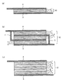
- FIG. 9 is a schematic cross-sectional view showing an example of the method for producing an all solid state battery of the present invention. Specifically, a manufacturing method using the battery element shown in FIG. 8 is shown.
- a first laminate 41 having a plurality of positive electrode active material layers 1 and an insulating layer 9 a formed between adjacent positive electrode active material layers 1 on the surface of the positive electrode current collector 4.
- a second electrode having a plurality of laminated units composed of the negative electrode active material layer 2 and the solid electrolyte layer 3 and an insulating layer 9b formed between adjacent laminated units on the surface of the negative electrode current collector 5.
- a laminated body 42 is prepared. Next, as shown in FIG.
- the positive electrode active material layer 1 of the first laminate 41 and the solid electrolyte layer 3 of the second laminate 42 are brought into close contact with each other.
- the insulating layer 9a and the insulating layer 9b are also in close contact.
- an insulating adhesive may be applied to the interface between them. In this way, the battery element 11 is obtained.
- the battery element 11 is sealed with the exterior body 7 to obtain the battery element-containing exterior body 12.
- the battery element-containing exterior body 12 may be pressurized by a general pressurizing method such as a flat press or a roll press before the isotropic pressure is applied.
- the battery element-containing exterior body 12 is bent at the positions of the insulating layers 9a and 9b. At this time, it is preferable to bend so that the adjacent power generation elements 10 face each other.
- the isotropic pressure device has, for example, a cylindrical chamber. However, if the inner diameter of the chamber is increased, the rigidity of the chamber itself needs to be increased at the same time.
- the thickness of the chamber proportional to the square of the inner diameter of the chamber or more, and the apparatus becomes large.
- the member to be pressed by bending the member to be pressed, the member to be pressed can be arranged at a high density in the isotropic pressure pressing device, and an all-solid battery can be manufactured efficiently. Can do.
- the insulating layers 9a and 9b are bent linearly, but the insulating layers 9a and 9b are bent in a curved manner (to have an R shape) in order to avoid sudden bending. May be.
- the pressed member bent as shown in FIG. 9 (d) may be used as an all-solid battery as it is, and a flat plate-like pressed member is formed by extending the bent portion. You may use it as an all-solid-state battery.
- a battery restraining jig 51 such as a bolt or a wire can be passed, and the all solid state battery can be restrained together with the pressing plate 52. Examples of the method for forming the through hole 15 include punching.
- FIG.10 (b) although the exterior body 7 shown in FIG.9 (d) is not described, in this invention, after an isotropic pressure pressurization, an exterior body is once removed and all solids are removed.
- the battery may be restrained or the all solid state battery may be restrained without removing the outer package.
- the insulating adhesive material for at least one part of an insulating layer. This is because outside air can be prevented from entering the inside of the battery from the through hole.
- the insulating layer 9a (insulating layer formed on the positive electrode active material layer side) and the insulating layer 9b (insulating layer formed on the negative electrode active material layer side) shown in FIG. ) Is composed of an insulating tape, and has an insulating adhesive at the interface between the two.
- the insulating layer 9a (insulating layer formed on the positive electrode active material layer side) and the insulating layer 9b (formed on the negative electrode active material layer side) shown in FIG.
- One of the insulating layers is an insulating tape, and the other is an insulating adhesive.
- the insulating layer may be composed only of an insulating adhesive material.
- L 2 is preferably at 2mm or more, 5 mm More preferably, it is in the range of ⁇ 10 mm. This is because if L 2 is too small, outside air may reach the power generation element, and if L 2 is too large, the energy density of the battery may be reduced.
- All-solid-state battery Examples of the all-solid-state battery obtained by the present invention include, for example, an all-solid lithium battery, an all-solid sodium battery, an all-solid magnesium battery, and an all-solid calcium battery. Is preferred.
- the all solid state battery obtained by the present invention may be a primary battery or a secondary battery, but is preferably a secondary battery. For example, it is useful as a vehicle-mounted battery.
- the present invention is not limited to the above embodiment.
- the above-described embodiment is an exemplification, and the present invention has substantially the same configuration as the technical idea described in the claims of the present invention, and any device that exhibits the same function and effect is the present invention. It is included in the technical scope of the invention.
- Example 1 LiNi 1/3 Co 1/3 Mn 1/3 O 2 ( positive electrode active material) and 75Li 2 S ⁇ 25P 2 S 5 glass (sulfide solid electrolyte material) in a weight ratio of 6: A slurry containing 4, aluminum foil Coating was performed on (positive electrode current collector) to obtain a positive electrode. Next, a slurry containing graphite (negative electrode active material) and 75Li 2 S ⁇ 25P 2 S 5 glass (sulfide solid electrolyte material) at a weight ratio of 6: 4 is applied onto a copper foil (negative electrode current collector). To obtain a negative electrode.
- a slurry containing 75Li 2 S ⁇ 25P 2 S 5 glass (sulfide solid electrolyte material) was applied on the negative electrode active material layer of the obtained negative electrode to form a solid electrolyte layer.
- the negative electrode and the positive electrode were laminated so that the solid electrolyte layer formed on the negative electrode was in contact with the positive electrode active material layer of the positive electrode, and punching was performed to obtain a battery element ( ⁇ 16 cm 2 ).
- the obtained battery element was covered with a water-resistant film and placed in a CIP device filled with water. In this state, isotropic pressure was applied under the conditions of 200 MPa, 25 ° C., and 5 minutes. As a result, an all-solid secondary battery was obtained.
- Example 2 to 5 An all-solid secondary battery was obtained in the same manner as in Example 1 except that the conditions for isotropic pressure application were changed as shown in Table 1 below.
- Example 1 The battery element obtained in Example 1 was pressurized (25 ° C.) with a roll press to obtain an all-solid secondary battery.
- the conditions of the roll press were as shown in Table 2 below. The linear pressure was adjusted by the gap between the upper and lower rollers.
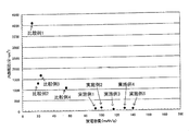
- the all solid state secondary batteries obtained in Examples 1 to 5 have higher discharge capacity and lower internal resistance than the all solid state secondary batteries obtained in Comparative Examples 1 to 4. It was confirmed.
Landscapes
- Chemical & Material Sciences (AREA)
- Chemical Kinetics & Catalysis (AREA)
- Electrochemistry (AREA)
- General Chemical & Material Sciences (AREA)
- Engineering & Computer Science (AREA)
- Manufacturing & Machinery (AREA)
- Physics & Mathematics (AREA)
- Condensed Matter Physics & Semiconductors (AREA)
- General Physics & Mathematics (AREA)
- Inorganic Chemistry (AREA)
- Secondary Cells (AREA)
- Battery Electrode And Active Subsutance (AREA)
- Sealing Battery Cases Or Jackets (AREA)
- Battery Mounting, Suspending (AREA)
Abstract
Priority Applications (3)
| Application Number | Priority Date | Filing Date | Title |
|---|---|---|---|
| US14/116,564 US20140082931A1 (en) | 2011-06-02 | 2011-06-02 | Method for producing all solid state battery |
| JP2013517778A JPWO2012164723A1 (ja) | 2011-06-02 | 2011-06-02 | 全固体電池の製造方法 |
| PCT/JP2011/062713 WO2012164723A1 (fr) | 2011-06-02 | 2011-06-02 | Procédé de formation d'une cellule entièrement à semi-conducteurs |
Applications Claiming Priority (1)
| Application Number | Priority Date | Filing Date | Title |
|---|---|---|---|
| PCT/JP2011/062713 WO2012164723A1 (fr) | 2011-06-02 | 2011-06-02 | Procédé de formation d'une cellule entièrement à semi-conducteurs |
Publications (1)
| Publication Number | Publication Date |
|---|---|
| WO2012164723A1 true WO2012164723A1 (fr) | 2012-12-06 |
Family
ID=47258608
Family Applications (1)
| Application Number | Title | Priority Date | Filing Date |
|---|---|---|---|
| PCT/JP2011/062713 Ceased WO2012164723A1 (fr) | 2011-06-02 | 2011-06-02 | Procédé de formation d'une cellule entièrement à semi-conducteurs |
Country Status (3)
| Country | Link |
|---|---|
| US (1) | US20140082931A1 (fr) |
| JP (1) | JPWO2012164723A1 (fr) |
| WO (1) | WO2012164723A1 (fr) |
Cited By (26)
| Publication number | Priority date | Publication date | Assignee | Title |
|---|---|---|---|---|
| JP2014120199A (ja) * | 2012-12-12 | 2014-06-30 | Samsung R&D Institute Japan Co Ltd | 固体電池 |
| WO2014111789A1 (fr) * | 2013-01-15 | 2014-07-24 | Toyota Jidosha Kabushiki Kaisha | Batterie entièrement à l'état solide et son procédé de fabrication |
| JP2015515094A (ja) * | 2012-03-28 | 2015-05-21 | ▲海▼洋王照明科技股▲ふん▼有限公司 | 固体電解質電池 |
| CN105830269A (zh) * | 2013-12-26 | 2016-08-03 | 丰田自动车株式会社 | 锂固体电池、锂固体电池模块及锂固体电池的制造方法 |
| JP2016152204A (ja) * | 2015-02-19 | 2016-08-22 | 三星電子株式会社Samsung Electronics Co.,Ltd. | 固体電池及びその製造方法 |
| EP3220446A1 (fr) * | 2016-03-17 | 2017-09-20 | Kabushiki Kaisha Toshiba | Batterie, batterie et véhicule |
| US9837684B2 (en) | 2015-02-19 | 2017-12-05 | Samsung Electronics Co., Ltd. | All solid secondary battery and method of manufacturing the same |
| US9985314B2 (en) | 2013-01-15 | 2018-05-29 | Toyota Jidosha Kabushiki Kaisha | All-solid battery and method for manufacturing the same |
| KR20180093250A (ko) * | 2018-08-07 | 2018-08-21 | 이창규 | 복수의 셀 영역들이 구비된 전기화학 에너지 소자 및 그 제조 방법 |
| KR101899949B1 (ko) * | 2016-07-01 | 2018-09-19 | 이창규 | 복수의 셀 영역들이 구비된 전기화학 에너지 소자 및 그 제조 방법 |
| WO2019155940A1 (fr) * | 2018-02-08 | 2019-08-15 | 日立造船株式会社 | Accumulateur entièrement solide et son procédé de production |
| JPWO2018168549A1 (ja) * | 2017-03-13 | 2019-11-07 | 富士フイルム株式会社 | 全固体二次電池及びその製造方法 |
| JP2020068170A (ja) * | 2018-10-26 | 2020-04-30 | トヨタ自動車株式会社 | 全固体電池の製造方法 |
| US20220029223A1 (en) * | 2018-09-27 | 2022-01-27 | Research Institute Of Industrial Science & Technology | Sodium secondary battery module |
| JP2022513762A (ja) * | 2018-12-11 | 2022-02-09 | テラワット テクノロジー インコーポレイテッド | 固体電池のための油圧式等方圧プレスプロセス |
| WO2022118938A1 (fr) * | 2020-12-02 | 2022-06-09 | 大日本印刷株式会社 | Film de traitement destiné à être utilisé dans la fabrication d'une batterie entièrement solide et procédé de fabrication de batterie entièrement solide |
| JP2022545706A (ja) * | 2020-03-24 | 2022-10-28 | エルジー エナジー ソリューション リミテッド | 全固体電池用リチウム金属単位セルの製造方法及びそれによって製造された単位セル |
| JPWO2022264601A1 (fr) * | 2021-06-17 | 2022-12-22 | ||
| JP2023008961A (ja) * | 2021-07-02 | 2023-01-19 | トヨタ自動車株式会社 | 全固体電池の製造方法 |
| JP2023097860A (ja) * | 2021-12-28 | 2023-07-10 | 株式会社スギノマシン | 全固体電池用原料の加圧装置および処理システム |
| JP2023102760A (ja) * | 2022-01-12 | 2023-07-25 | ハナ テクノロジー カンパニー リミテッド | 全固体用二次電池高温加圧システム及び方法 |
| JP2023536129A (ja) * | 2021-04-09 | 2023-08-23 | エルジー エナジー ソリューション リミテッド | 全固体電池の製造方法及びこれによる全固体電池 |
| CN118299673A (zh) * | 2024-06-06 | 2024-07-05 | 中能瑞新(深圳)能源科技有限公司 | 一种钠离子固态电池及其制备方法 |
| JP2024160640A (ja) * | 2023-05-01 | 2024-11-14 | トヨタ自動車株式会社 | 全固体電池の製造方法及び全固体電池 |
| WO2025013412A1 (fr) * | 2023-07-07 | 2025-01-16 | 日立造船株式会社 | Unité de batterie à électrolyte solide, empilement de batteries à électrolyte solide, bloc-batterie à électrolyte solide, procédé de fabrication d'une unité de batterie à électrolyte solide et procédé de fabrication d'un empilement de batteries à électrolyte solide |
| WO2025071192A1 (fr) * | 2023-09-26 | 2025-04-03 | 주식회사 엘지에너지솔루션 | Procédé de pressage isostatique d'ensemble électrode à l'aide d'un élément de protection en tant que cadre sacrificiel externe, et batterie entièrement solide comprenant un élément de protection |
Families Citing this family (20)
| Publication number | Priority date | Publication date | Assignee | Title |
|---|---|---|---|---|
| KR102359583B1 (ko) * | 2017-05-08 | 2022-02-07 | 현대자동차주식회사 | 고체전해질 및 이를 포함하는 전고체 전지의 제조방법 |
| US11264641B2 (en) | 2018-01-10 | 2022-03-01 | Samsung Electronics Co., Ltd. | All-solid secondary battery, multilayered all-solid secondary battery, and method of manufacturing all-solid secondary battery |
| ES2745350B2 (es) * | 2018-08-28 | 2021-11-16 | Torres Martinez M | Bateria electroquimica presurizada y proceso de fabricacion de la misma |
| KR102728661B1 (ko) | 2018-09-06 | 2024-11-11 | 삼성전자주식회사 | 고체 전해질, 그 제조방법 및 이를 포함하는 이차전지 |
| KR102650658B1 (ko) | 2018-11-15 | 2024-03-25 | 삼성전자주식회사 | 헤테로고리 방향족 구조의 음이온을 포함하는 금속염 및 그 제조방법, 그리고 상기 금속염을 포함하는 전해질 및 전기화학소자 |
| US11411246B2 (en) | 2018-12-06 | 2022-08-09 | Samsung Electronics Co., Ltd. | All-solid secondary battery and method of manufacturing all-solid secondary battery |
| JP7167724B2 (ja) * | 2019-01-11 | 2022-11-09 | トヨタ自動車株式会社 | 全固体電池 |
| KR102764107B1 (ko) * | 2019-05-03 | 2025-02-05 | 현대자동차주식회사 | 고에너지 밀도 전고체 전지 및 이의 제조 방법 |
| US11715845B2 (en) | 2019-09-02 | 2023-08-01 | Samsung Electronics Co., Ltd. | All solid battery |
| CN115117367B (zh) * | 2021-03-18 | 2025-10-28 | 辉能科技股份有限公司 | 电极组件及其电池装置 |
| US20220302463A1 (en) * | 2021-03-18 | 2022-09-22 | Prologium Technology Co., Ltd. | Electrode assembly and its battery device thereof |
| US20230207805A1 (en) * | 2021-03-19 | 2023-06-29 | Sekisui Chemical Co., Ltd. | Positive electrode for non-aqueous electrolyte secondary battery, and non-aqueous electrolyte secondary battery, battery module and battery system using the same |
| WO2023008821A1 (fr) * | 2021-07-30 | 2023-02-02 | 삼성에스디아이주식회사 | Batterie rechargeable tout solide, structure de batterie rechargeable tout solide, et procédé de fabrication de batterie rechargeable tout solide |
| KR102927419B1 (ko) * | 2022-02-10 | 2026-02-12 | 삼성에스디아이 주식회사 | 전고체 전지용 탄성 시트 조성물, 이로부터 제조된 전고체 전지용 탄성시트, 및 이를 포함하는 전고체 전지 |
| WO2024238432A1 (fr) | 2023-05-15 | 2024-11-21 | Factorial Inc. | Ensemble de cellules densifiées et son procédé de préparation |
| KR102824222B1 (ko) * | 2024-01-15 | 2025-06-24 | (주)하나기술 | 전고체용 이차전지 가압 기밀장치 |
| DE102024107276A1 (de) | 2024-03-14 | 2025-09-18 | Bayerische Motoren Werke Aktiengesellschaft | Verfahren zum Herstellen einer Feststoffbatterie und Feststoffbatterie |
| KR20250171814A (ko) * | 2024-05-30 | 2025-12-09 | 삼성에스디아이 주식회사 | 전지 원심 가압기 및 이를 이용한 전고체 전지 제조 방법 |
| CN118380664A (zh) * | 2024-06-21 | 2024-07-23 | 宁德时代新能源科技股份有限公司 | 全固态电池的制备方法以及全固态电池 |
| CN121769254A (zh) * | 2024-09-30 | 2026-03-31 | 宁德时代新能源科技股份有限公司 | 一种电极组件的制备方法 |
Citations (5)
| Publication number | Priority date | Publication date | Assignee | Title |
|---|---|---|---|---|
| JPH07220754A (ja) * | 1994-02-07 | 1995-08-18 | Tdk Corp | 積層型リチウム二次電池 |
| JP2003086251A (ja) * | 2001-09-06 | 2003-03-20 | Sony Corp | 二次電池の製造方法 |
| JP2008103284A (ja) * | 2006-10-20 | 2008-05-01 | Idemitsu Kosan Co Ltd | 全固体電池 |
| JP2009193894A (ja) * | 2008-02-15 | 2009-08-27 | Ohara Inc | グリーンシート積層体の製造方法 |
| JP2011065913A (ja) * | 2009-09-18 | 2011-03-31 | Sumitomo Electric Ind Ltd | 非水固体電解質電池およびその製造方法 |
Family Cites Families (4)
| Publication number | Priority date | Publication date | Assignee | Title |
|---|---|---|---|---|
| JPH06203830A (ja) * | 1992-12-29 | 1994-07-22 | Haibaru:Kk | 電 池 |
| JPH11144715A (ja) * | 1997-11-10 | 1999-05-28 | Agency Of Ind Science & Technol | 二次電池の電極製造方法 |
| US7541715B2 (en) * | 2004-06-14 | 2009-06-02 | Massachusetts Institute Of Technology | Electrochemical methods, devices, and structures |
| JP2009266740A (ja) * | 2008-04-28 | 2009-11-12 | Idemitsu Kosan Co Ltd | 電池モジュール、電池モジュールの製造方法及び電池モジュールを備えた装置 |
-
2011
- 2011-06-02 JP JP2013517778A patent/JPWO2012164723A1/ja active Pending
- 2011-06-02 US US14/116,564 patent/US20140082931A1/en not_active Abandoned
- 2011-06-02 WO PCT/JP2011/062713 patent/WO2012164723A1/fr not_active Ceased
Patent Citations (5)
| Publication number | Priority date | Publication date | Assignee | Title |
|---|---|---|---|---|
| JPH07220754A (ja) * | 1994-02-07 | 1995-08-18 | Tdk Corp | 積層型リチウム二次電池 |
| JP2003086251A (ja) * | 2001-09-06 | 2003-03-20 | Sony Corp | 二次電池の製造方法 |
| JP2008103284A (ja) * | 2006-10-20 | 2008-05-01 | Idemitsu Kosan Co Ltd | 全固体電池 |
| JP2009193894A (ja) * | 2008-02-15 | 2009-08-27 | Ohara Inc | グリーンシート積層体の製造方法 |
| JP2011065913A (ja) * | 2009-09-18 | 2011-03-31 | Sumitomo Electric Ind Ltd | 非水固体電解質電池およびその製造方法 |
Cited By (52)
| Publication number | Priority date | Publication date | Assignee | Title |
|---|---|---|---|---|
| JP2015515094A (ja) * | 2012-03-28 | 2015-05-21 | ▲海▼洋王照明科技股▲ふん▼有限公司 | 固体電解質電池 |
| JP2014120199A (ja) * | 2012-12-12 | 2014-06-30 | Samsung R&D Institute Japan Co Ltd | 固体電池 |
| US9985314B2 (en) | 2013-01-15 | 2018-05-29 | Toyota Jidosha Kabushiki Kaisha | All-solid battery and method for manufacturing the same |
| WO2014111789A1 (fr) * | 2013-01-15 | 2014-07-24 | Toyota Jidosha Kabushiki Kaisha | Batterie entièrement à l'état solide et son procédé de fabrication |
| CN104919628A (zh) * | 2013-01-15 | 2015-09-16 | 丰田自动车株式会社 | 全固态电池和用于制造该全固态电池的方法 |
| DE112014000438B4 (de) | 2013-01-15 | 2023-01-05 | Toyota Jidosha Kabushiki Kaisha | Festkörperbatterie und Verfahren zum Herstellen derselben |
| TWI555257B (zh) * | 2013-01-15 | 2016-10-21 | 豐田自動車股份有限公司 | 全固態電池及彼之製法 |
| US10079383B2 (en) | 2013-01-15 | 2018-09-18 | Toyota Jidosha Kabushiki Kaisha | All-solid battery and method for manufacturing the same |
| CN104919628B (zh) * | 2013-01-15 | 2017-08-15 | 丰田自动车株式会社 | 全固态电池和用于制造该全固态电池的方法 |
| CN105830269B (zh) * | 2013-12-26 | 2019-02-22 | 丰田自动车株式会社 | 锂固体电池、锂固体电池模块及锂固体电池的制造方法 |
| EP3089254A4 (fr) * | 2013-12-26 | 2017-01-04 | Toyota Jidosha Kabushiki Kaisha | Batterie au lithium à électrolyte solide, module de batteries au lithium à électrolyte solide, et procédé de production d'une batterie au lithium à électrolyte solide |
| CN105830269A (zh) * | 2013-12-26 | 2016-08-03 | 丰田自动车株式会社 | 锂固体电池、锂固体电池模块及锂固体电池的制造方法 |
| US10141602B2 (en) | 2013-12-26 | 2018-11-27 | Toyota Jidosha Kabushiki Kaisha | Lithium solid battery, lithium solid battery module, and producing method for lithium solid battery |
| JP2016152204A (ja) * | 2015-02-19 | 2016-08-22 | 三星電子株式会社Samsung Electronics Co.,Ltd. | 固体電池及びその製造方法 |
| US9837684B2 (en) | 2015-02-19 | 2017-12-05 | Samsung Electronics Co., Ltd. | All solid secondary battery and method of manufacturing the same |
| EP3220446A1 (fr) * | 2016-03-17 | 2017-09-20 | Kabushiki Kaisha Toshiba | Batterie, batterie et véhicule |
| US10541442B2 (en) | 2016-03-17 | 2020-01-21 | Kabushiki Kaisha Toshiba | Battery, battery pack, and vehicle |
| KR101899949B1 (ko) * | 2016-07-01 | 2018-09-19 | 이창규 | 복수의 셀 영역들이 구비된 전기화학 에너지 소자 및 그 제조 방법 |
| JPWO2018168549A1 (ja) * | 2017-03-13 | 2019-11-07 | 富士フイルム株式会社 | 全固体二次電池及びその製造方法 |
| JP7133316B2 (ja) | 2018-02-08 | 2022-09-08 | 日立造船株式会社 | 全固体二次電池およびその製造方法 |
| JP2019139892A (ja) * | 2018-02-08 | 2019-08-22 | 日立造船株式会社 | 全固体二次電池およびその製造方法 |
| WO2019155940A1 (fr) * | 2018-02-08 | 2019-08-15 | 日立造船株式会社 | Accumulateur entièrement solide et son procédé de production |
| KR101949931B1 (ko) * | 2018-08-07 | 2019-03-12 | 주식회사 유뱃 | 복수의 셀 영역들이 구비된 전기화학 에너지 소자 및 그 제조 방법 |
| KR20180093250A (ko) * | 2018-08-07 | 2018-08-21 | 이창규 | 복수의 셀 영역들이 구비된 전기화학 에너지 소자 및 그 제조 방법 |
| US20220029223A1 (en) * | 2018-09-27 | 2022-01-27 | Research Institute Of Industrial Science & Technology | Sodium secondary battery module |
| US11901538B2 (en) * | 2018-09-27 | 2024-02-13 | Research Institute Of Industrial Science & Technology | Sodium secondary battery module |
| JP2020068170A (ja) * | 2018-10-26 | 2020-04-30 | トヨタ自動車株式会社 | 全固体電池の製造方法 |
| JP7259263B2 (ja) | 2018-10-26 | 2023-04-18 | トヨタ自動車株式会社 | 全固体電池の製造方法 |
| JP2022513762A (ja) * | 2018-12-11 | 2022-02-09 | テラワット テクノロジー インコーポレイテッド | 固体電池のための油圧式等方圧プレスプロセス |
| JP7570697B2 (ja) | 2018-12-11 | 2024-10-22 | テラワット テクノロジー インコーポレイテッド | 固体電池のための油圧式等方圧プレスプロセス |
| JP2022545706A (ja) * | 2020-03-24 | 2022-10-28 | エルジー エナジー ソリューション リミテッド | 全固体電池用リチウム金属単位セルの製造方法及びそれによって製造された単位セル |
| JP7515834B2 (ja) | 2020-03-24 | 2024-07-16 | エルジー エナジー ソリューション リミテッド | 全固体電池用リチウム金属単位セルの製造方法及びそれによって製造された単位セル |
| WO2022118938A1 (fr) * | 2020-12-02 | 2022-06-09 | 大日本印刷株式会社 | Film de traitement destiné à être utilisé dans la fabrication d'une batterie entièrement solide et procédé de fabrication de batterie entièrement solide |
| EP4257358A4 (fr) * | 2020-12-02 | 2025-12-03 | Dainippon Printing Co Ltd | Film de traitement destiné à être utilisé dans la fabrication d'une batterie entièrement solide et procédé de fabrication de batterie entièrement solide |
| JP7151942B1 (ja) * | 2020-12-02 | 2022-10-12 | 大日本印刷株式会社 | 全固体電池の製造に用いられる工程フィルム、及び全固体電池の製造方法 |
| JP7531976B2 (ja) | 2021-04-09 | 2024-08-13 | エルジー エナジー ソリューション リミテッド | 全固体電池の製造方法及びこれによる全固体電池 |
| JP2023536129A (ja) * | 2021-04-09 | 2023-08-23 | エルジー エナジー ソリューション リミテッド | 全固体電池の製造方法及びこれによる全固体電池 |
| WO2022264601A1 (fr) | 2021-06-17 | 2022-12-22 | ビークルエナジージャパン株式会社 | Batterie à électrolyte solide, procédé de fabrication de batterie à électrolyte solide et appareil de transport |
| JPWO2022264601A1 (fr) * | 2021-06-17 | 2022-12-22 | ||
| JP7651697B2 (ja) | 2021-06-17 | 2025-03-26 | ビークルエナジージャパン株式会社 | 固体電解質電池、及び輸送機器 |
| JP2023008961A (ja) * | 2021-07-02 | 2023-01-19 | トヨタ自動車株式会社 | 全固体電池の製造方法 |
| JP7647697B2 (ja) | 2021-07-02 | 2025-03-18 | トヨタ自動車株式会社 | 全固体電池の製造方法 |
| JP7676088B2 (ja) | 2021-12-28 | 2025-05-14 | 株式会社スギノマシン | 全固体電池用原料の加圧装置、処理システムおよび固形状の全固体電池用原料を生産する方法 |
| JP2023097860A (ja) * | 2021-12-28 | 2023-07-10 | 株式会社スギノマシン | 全固体電池用原料の加圧装置および処理システム |
| JP7467807B2 (ja) | 2022-01-12 | 2024-04-16 | ハナ テクノロジー カンパニー リミテッド | 全固体用二次電池高温加圧システム及び方法 |
| JP2023102760A (ja) * | 2022-01-12 | 2023-07-25 | ハナ テクノロジー カンパニー リミテッド | 全固体用二次電池高温加圧システム及び方法 |
| JP2024160640A (ja) * | 2023-05-01 | 2024-11-14 | トヨタ自動車株式会社 | 全固体電池の製造方法及び全固体電池 |
| JP7768190B2 (ja) | 2023-05-01 | 2025-11-12 | トヨタ自動車株式会社 | 全固体電池の製造方法及び全固体電池 |
| WO2025013412A1 (fr) * | 2023-07-07 | 2025-01-16 | 日立造船株式会社 | Unité de batterie à électrolyte solide, empilement de batteries à électrolyte solide, bloc-batterie à électrolyte solide, procédé de fabrication d'une unité de batterie à électrolyte solide et procédé de fabrication d'un empilement de batteries à électrolyte solide |
| WO2025071192A1 (fr) * | 2023-09-26 | 2025-04-03 | 주식회사 엘지에너지솔루션 | Procédé de pressage isostatique d'ensemble électrode à l'aide d'un élément de protection en tant que cadre sacrificiel externe, et batterie entièrement solide comprenant un élément de protection |
| CN118299673B (zh) * | 2024-06-06 | 2024-08-30 | 中能瑞新(深圳)能源科技有限公司 | 一种钠离子固态电池及其制备方法 |
| CN118299673A (zh) * | 2024-06-06 | 2024-07-05 | 中能瑞新(深圳)能源科技有限公司 | 一种钠离子固态电池及其制备方法 |
Also Published As
| Publication number | Publication date |
|---|---|
| JPWO2012164723A1 (ja) | 2014-07-31 |
| US20140082931A1 (en) | 2014-03-27 |
Similar Documents
| Publication | Publication Date | Title |
|---|---|---|
| WO2012164723A1 (fr) | Procédé de formation d'une cellule entièrement à semi-conducteurs | |
| EP3913711B1 (fr) | Plaque d'électrode, appareil électrochimique et appareil associé | |
| EP2894705B1 (fr) | Procédé de production de batterie entièrement à électrolyte solide et ladite batterie | |
| CN104412440B (zh) | 全固体电池及其制造方法 | |
| CN104919627B (zh) | 全固体电池及其制造方法 | |
| JP2022044461A (ja) | 全固体二次電池、積層全固体二次電池及びこれらの製造方法 | |
| JP6259704B2 (ja) | 全固体電池用電極の製造方法及び全固体電池の製造方法 | |
| JPWO2012014780A1 (ja) | 双極型電極およびそれを用いた双極型二次電池並びに双極型電極の製造方法 | |
| WO2021000547A1 (fr) | Pièce polaire positive, dispositif électrochimique et dispositif | |
| WO2022057189A1 (fr) | Batterie à semi-conducteur, module de batterie, bloc-batterie, et dispositif associé | |
| WO2014010042A1 (fr) | Procédé de production d'une batterie tout électronique | |
| WO2017217079A1 (fr) | Batterie entièrement solide | |
| WO2016157348A1 (fr) | Batterie secondaire au lithium entièrement solide de type volume | |
| US20180294531A1 (en) | Method of producing all-solid battery | |
| JP2014102982A (ja) | 全固体電池及びその製造方法 | |
| JP5806335B2 (ja) | 電極体及びその製造方法 | |
| JP2015005421A (ja) | 電極体及び全固体電池 | |
| KR102764107B1 (ko) | 고에너지 밀도 전고체 전지 및 이의 제조 방법 | |
| JP2014116136A (ja) | 全固体二次電池 | |
| CN115792617A (zh) | 一种全固态电池极片短路检测方法 | |
| JP2020024779A (ja) | 二次電池用電極、二次電池、それらの製造方法 | |
| JP2015216077A (ja) | 全固体電池の製造方法 | |
| JP7770791B2 (ja) | 全固体二次電池、積層全固体二次電池 | |
| JP6256451B2 (ja) | 全固体電池 | |
| JP6128228B2 (ja) | 負極活物質、それを用いた負極、及びリチウムイオン二次電池 |
Legal Events
| Date | Code | Title | Description |
|---|---|---|---|
| 121 | Ep: the epo has been informed by wipo that ep was designated in this application |
Ref document number: 11866476 Country of ref document: EP Kind code of ref document: A1 |
|
| ENP | Entry into the national phase |
Ref document number: 2013517778 Country of ref document: JP Kind code of ref document: A |
|
| WWE | Wipo information: entry into national phase |
Ref document number: 14116564 Country of ref document: US |
|
| NENP | Non-entry into the national phase |
Ref country code: DE |
|
| 122 | Ep: pct application non-entry in european phase |
Ref document number: 11866476 Country of ref document: EP Kind code of ref document: A1 |