WO2012164784A1 - 減速情報伝達装置、減速情報伝達方法 - Google Patents
減速情報伝達装置、減速情報伝達方法 Download PDFInfo
- Publication number
- WO2012164784A1 WO2012164784A1 PCT/JP2012/001187 JP2012001187W WO2012164784A1 WO 2012164784 A1 WO2012164784 A1 WO 2012164784A1 JP 2012001187 W JP2012001187 W JP 2012001187W WO 2012164784 A1 WO2012164784 A1 WO 2012164784A1
- Authority
- WO
- WIPO (PCT)
- Prior art keywords
- deceleration
- deceleration information
- driver
- unit
- vehicle
- Prior art date
- Legal status (The legal status is an assumption and is not a legal conclusion. Google has not performed a legal analysis and makes no representation as to the accuracy of the status listed.)
- Ceased
Links
Images





Classifications
-
- G—PHYSICS
- G01—MEASURING; TESTING
- G01P—MEASURING LINEAR OR ANGULAR SPEED, ACCELERATION, DECELERATION, OR SHOCK; INDICATING PRESENCE, ABSENCE, OR DIRECTION, OF MOVEMENT
- G01P1/00—Details of instruments
- G01P1/07—Indicating devices, e.g. for remote indication
-
- B—PERFORMING OPERATIONS; TRANSPORTING
- B60—VEHICLES IN GENERAL
- B60Q—ARRANGEMENT OF SIGNALLING OR LIGHTING DEVICES, THE MOUNTING OR SUPPORTING THEREOF OR CIRCUITS THEREFOR, FOR VEHICLES IN GENERAL
- B60Q1/00—Arrangement of optical signalling or lighting devices, the mounting or supporting thereof or circuits therefor
-
- B—PERFORMING OPERATIONS; TRANSPORTING
- B60—VEHICLES IN GENERAL
- B60W—CONJOINT CONTROL OF VEHICLE SUB-UNITS OF DIFFERENT TYPE OR DIFFERENT FUNCTION; CONTROL SYSTEMS SPECIALLY ADAPTED FOR HYBRID VEHICLES; ROAD VEHICLE DRIVE CONTROL SYSTEMS FOR PURPOSES NOT RELATED TO THE CONTROL OF A PARTICULAR SUB-UNIT
- B60W50/00—Details of control systems for road vehicle drive control not related to the control of a particular sub-unit, e.g. process diagnostic or vehicle driver interfaces
- B60W50/08—Interaction between the driver and the control system
- B60W50/14—Means for informing the driver, warning the driver or prompting a driver intervention
-
- B—PERFORMING OPERATIONS; TRANSPORTING
- B60—VEHICLES IN GENERAL
- B60W—CONJOINT CONTROL OF VEHICLE SUB-UNITS OF DIFFERENT TYPE OR DIFFERENT FUNCTION; CONTROL SYSTEMS SPECIALLY ADAPTED FOR HYBRID VEHICLES; ROAD VEHICLE DRIVE CONTROL SYSTEMS FOR PURPOSES NOT RELATED TO THE CONTROL OF A PARTICULAR SUB-UNIT
- B60W2510/00—Input parameters relating to a particular sub-units
- B60W2510/06—Combustion engines, Gas turbines
- B60W2510/0657—Engine torque
-
- B—PERFORMING OPERATIONS; TRANSPORTING
- B60—VEHICLES IN GENERAL
- B60W—CONJOINT CONTROL OF VEHICLE SUB-UNITS OF DIFFERENT TYPE OR DIFFERENT FUNCTION; CONTROL SYSTEMS SPECIALLY ADAPTED FOR HYBRID VEHICLES; ROAD VEHICLE DRIVE CONTROL SYSTEMS FOR PURPOSES NOT RELATED TO THE CONTROL OF A PARTICULAR SUB-UNIT
- B60W2520/00—Input parameters relating to overall vehicle dynamics
- B60W2520/10—Longitudinal speed
- B60W2520/105—Longitudinal acceleration
-
- B—PERFORMING OPERATIONS; TRANSPORTING
- B60—VEHICLES IN GENERAL
- B60W—CONJOINT CONTROL OF VEHICLE SUB-UNITS OF DIFFERENT TYPE OR DIFFERENT FUNCTION; CONTROL SYSTEMS SPECIALLY ADAPTED FOR HYBRID VEHICLES; ROAD VEHICLE DRIVE CONTROL SYSTEMS FOR PURPOSES NOT RELATED TO THE CONTROL OF A PARTICULAR SUB-UNIT
- B60W2540/00—Input parameters relating to occupants
- B60W2540/10—Accelerator pedal position
-
- B—PERFORMING OPERATIONS; TRANSPORTING
- B60—VEHICLES IN GENERAL
- B60W—CONJOINT CONTROL OF VEHICLE SUB-UNITS OF DIFFERENT TYPE OR DIFFERENT FUNCTION; CONTROL SYSTEMS SPECIALLY ADAPTED FOR HYBRID VEHICLES; ROAD VEHICLE DRIVE CONTROL SYSTEMS FOR PURPOSES NOT RELATED TO THE CONTROL OF A PARTICULAR SUB-UNIT
- B60W30/00—Purposes of road vehicle drive control systems not related to the control of a particular sub-unit, e.g. of systems using conjoint control of vehicle sub-units
- B60W30/18—Propelling the vehicle
- B60W30/18009—Propelling the vehicle related to particular drive situations
- B60W30/18109—Braking
- B60W30/18127—Regenerative braking
Definitions
- the present invention relates to a deceleration information transmission device and a deceleration information transmission method.
- An object of the present invention is to more accurately transmit a deceleration situation such as a driver's intention to decelerate or a vehicle deceleration state.
- a vehicle deceleration control device detects a driving torque of a rotational driving source, and when the driving torque is a negative value, the driver's intention to decelerate and the vehicle according to the driving torque.
- the deceleration information representing at least one of the deceleration states is set, and the set deceleration information is transmitted to the driver.
- the degree of transmission of the deceleration situation is adjusted according to the negative driving torque, so the driver's intention to decelerate and the vehicle deceleration state The situation during deceleration such as can be transmitted more accurately.
- FIG. 1 is a system configuration diagram of a deceleration information transmission device.
- an engine torque sensor 11 that detects the engine torque Te
- a control unit 13 configured by, for example, a microcomputer, an amplifier 14, and a speaker 15
- the engine torque sensor 11 corresponds to a “drive torque detection unit”
- the control unit 13 corresponds to a “deceleration information setting unit”
- the speaker 15 corresponds to a “transmission unit”.
- the engine torque Te may be acquired by CAN communication, or the engine torque Te may be calculated based on the engine speed, the gear ratio, the vehicle speed, and the like. Further, although the case where the rotational drive source is an engine is described, in the case where the motor travels in a hybrid vehicle (HEV) or in the case of an electric vehicle (EV), the motor torque is used as the drive torque of the rotational drive source. Is detected.
- HEV hybrid vehicle
- EV electric vehicle
- the control unit 13 includes a volume adjustment primary expression storage unit 21, a volume adjustment allowance calculation unit 22, a frequency characteristic storage unit 23, an output frequency calculation unit 24, an output signal determination unit 25, and an output signal voltage conversion unit 26. And a code determination unit 27.
- the control unit 13 executes a deceleration state transmission control process and transmits to the driver a sound in which the volume changes according to the deceleration state (the driver's intention to decelerate or the vehicle's deceleration state) in real time. To do.
- the volume is adjusted using a volume adjustment coefficient kt determined in accordance with the engine torque Te when a signal representing the engine torque Te is obtained and the engine torque becomes a negative value.
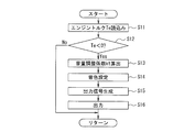
- FIG. 2 is a flowchart showing a deceleration state transmission control process.
- step S11 the engine torque Te is read.
- step S12 corresponds to the process in the sign determination unit 27, and determines whether or not the engine torque Te is a negative value. If the determination result is “Te ⁇ 0”, it is determined that the deceleration information indicating the deceleration intention or the deceleration state is unnecessary, and the process returns to the predetermined main program as it is. On the other hand, if the determination result is “Te ⁇ 0”, the process proceeds to step S13 in order to transmit the deceleration information to the driver.
- the subsequent step S13 corresponds to the processing in the volume adjustment allowance calculation unit 22, and calculates the volume adjustment coefficient kt corresponding to the engine torque Te by the volume adjustment primary expression stored in the volume adjustment primary expression storage unit 21.
- the volume adjustment linear expression is set so that the volume adjustment coefficient kt increases as the absolute value of the engine torque Te increases (increases toward the negative side).
- the subsequent step S14 corresponds to the processing in the output frequency calculation unit 24, and sets a tone color (deceleration sound) corresponding to the order component of the engine torque from the sound source data.
- the sound source data is a wav file, a midi file, or the like stored in advance in the frequency characteristic storage unit 23 of the control unit 13. This sound source data can be rewritten and can be selected by a change or preset file by an external terminal such as USB.
- the subsequent step S15 corresponds to the processing in the output signal determination unit 25, and generates an output signal according to the tone corresponding to the volume adjustment coefficient kt and the order component of the engine torque.
- the subsequent step S16 corresponds to the processing in the output signal voltage converter 26, converts the output signal to a voltage, outputs it to the amplifier 14, and outputs a deceleration sound via the speaker 15.
- At least one of the driver's intention to decelerate and the vehicle's decelerating state is transmitted to the driver by sound volume as a deceleration state.
- a volume adjustment coefficient kt is calculated according to the engine torque Te (S13), and according to the volume adjustment coefficient kt.
- a deceleration sound whose volume is adjusted is output (S14 to S16).
- the engine torque Te becomes a negative value, and the larger the value, the greater the deceleration caused by the engine brake. Therefore, information on the engine torque Te is acquired in real time, and when the engine torque Te is a negative value, the deceleration sound is increased as the absolute value of the engine torque Te increases. In this way, by controlling the volume with the engine torque Te having a correlation with the deceleration due to the engine brake, it is possible to control the volume more appropriately for the deceleration of the vehicle. From the above, the engine torque sensor 11 corresponds to the “drive torque detection unit”, the control unit 13 corresponds to the “deceleration information setting unit”, and the speaker 15 corresponds to the “transmission unit”.
- effect (1)
- the deceleration information transmission device when the engine torque Te is a negative value, the volume of the deceleration sound is adjusted according to the engine torque Te and transmitted to the driver.
- the degree of transmission of the deceleration situation is adjusted according to the negative engine torque Te, it is possible to more accurately convey the deceleration situation such as the driver's intention to decelerate or the deceleration state of the vehicle. Can do.
- deceleration information transmission device deceleration information is transmitted to the driver by outputting a deceleration sound through the speaker 15. Thereby, deceleration information can be easily transmitted to the driver.
- the deceleration information transmission method when the engine torque Te is a negative value, the volume of the deceleration sound is adjusted according to the engine torque Te and transmitted to the driver. As described above, since the degree of transmission of the deceleration situation is adjusted according to the negative engine torque Te, it is possible to more accurately convey the deceleration situation such as the driver's intention to decelerate or the deceleration state of the vehicle. Can do.
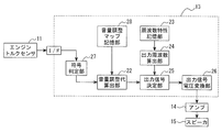
- FIG. 3 is a system configuration diagram of the deceleration information transmission apparatus showing the second embodiment.
- the control unit 13 includes a volume adjustment map storage unit 28, a volume adjustment allowance calculation unit 22, a frequency characteristic storage unit 23, an output frequency calculation unit 24, an output signal determination unit 25, an output signal voltage conversion unit 26, A code determination unit 27.
- FIG. 4 is a map used for calculating the volume adjustment coefficient kt.
- the volume adjustment coefficient kt increases as the engine torque Te increases toward the negative side.
- the characteristic line has an inverted S shape. That is, the increase rate of the volume adjustment coefficient kt with respect to the engine torque Te is set so that the increase rate is small in a region where the absolute value of the engine torque Te is small and large and the increase rate is large in an intermediate region.
- volume control with a degree of freedom can be performed. That is, the volume can be adjusted according to the background noise and the state of the engine and transmission of the vehicle, increasing the degree of freedom. Furthermore, by making the characteristic line into an inverted S shape, when the deceleration gradually increases, that is, when it is necessary to know that the speed reduction rate is increasing and decelerating, the deceleration sound is effectively used. Can be communicated to the driver.
- effect (1)
- a map in which the volume adjustment coefficient kt is determined according to the engine torque Te is referred to.
- the map control enables easy volume control with a degree of freedom.
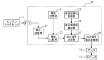
- FIG. 5 is a system configuration diagram of the deceleration information transmission apparatus showing the third embodiment.
- the control unit 13 includes a threshold storage unit 31, a threshold comparison unit 32, a frequency characteristic storage unit 23, an output frequency calculation unit 24, an output signal determination unit 25, an output signal voltage conversion unit 26, and a code determination unit 27. And comprising.
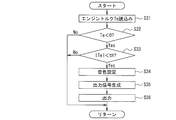
- FIG. 6 is a flowchart illustrating a deceleration state transmission control process according to the third embodiment.
- step S31 the engine torque Te is read.
- step S32 corresponds to the process in the sign determination unit 27, and determines whether or not the engine torque Te is a negative value. If the determination result is “Te ⁇ 0”, it is determined that the deceleration information indicating the deceleration intention or the deceleration state is unnecessary, and the process returns to the predetermined main program as it is. On the other hand, if the determination result is “Te ⁇ 0”, the process proceeds to step S33.
- the subsequent step S33 corresponds to the processing in the threshold value comparison unit 32, refers to the threshold value th stored in advance in the threshold value storage unit 31, and determines whether or not the absolute value of the engine torque Te is larger than the threshold value th. If the determination result is “
- Step S34 corresponds to the processing in the output frequency calculation unit 24, and sets a tone color (deceleration sound) corresponding to the order component of the engine torque from the sound source data.
- the sound source data is a wav file, a midi file, or the like stored in advance in the frequency characteristic storage unit 23 of the control unit 13. This sound source data can be rewritten and can be selected by a change or preset file by an external terminal such as USB.
- an output signal is generated according to the tone corresponding to the order component of the engine torque, corresponding to the processing in the output signal determination unit 25.
- the output signal is converted into a voltage, outputted to the amplifier 14, and a deceleration sound is outputted via the speaker 15.
- a threshold value th for the negative engine torque Te is set, and a deceleration sound is output when the absolute value
- FIG. 7 is a system configuration diagram of the deceleration information transmission apparatus showing the fourth embodiment.
- a vehicle speed sensor 16 a control unit 13 configured by, for example, a microcomputer, an amplifier 14, and a speaker 15 are provided.
- the control unit 13 corresponds to a “deceleration information setting unit”
- the speaker 15 corresponds to a “transmission unit”.
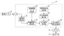
- the control unit 13 includes a deceleration calculation unit 33, a volume adjustment map storage unit 28, a volume adjustment allowance calculation unit 22, a frequency characteristic storage unit 23, an output frequency calculation unit 24, an output signal determination unit 25, and an output. And a signal voltage conversion unit 26.
- the deceleration calculation unit 33 corresponds to a “deceleration detection unit”.
- the control unit 13 executes a deceleration state transmission control process and transmits to the driver a sound in which the volume changes according to the deceleration state (the driver's intention to decelerate or the vehicle's deceleration state) in real time.
- the deceleration G is calculated based on a change amount (for example, a differential value) of the unit time value of the vehicle speed, and is adjusted using the volume adjustment coefficient kg determined according to the deceleration G with reference to the map of FIG. To do.
- FIG. 8 is a map used for calculating the volume adjustment coefficient kg.
- the volume adjustment coefficient kt increases as the deceleration G increases.
- the characteristic line has an inverted S shape. That is, the increase rate of the volume adjustment coefficient kt with respect to the deceleration G is set such that the increase rate is small in the region where the deceleration G is small and the region where the deceleration G is large and the increase rate is large in the intermediate region.
- At least one of the driver's intention to decelerate and the vehicle's decelerating state is transmitted to the driver by sound volume as a deceleration state.
- the volume adjustment coefficient kg is calculated according to the deceleration G, and the volume is adjusted according to the volume adjustment coefficient kt.
- the deceleration calculation unit 33 corresponds to the “deceleration detection unit”.
- the vehicle deceleration G is calculated based on the vehicle speed, and the volume of the deceleration sound is adjusted according to the deceleration G and transmitted to the driver.
- the deceleration situation such as the driver's intention to decelerate and the deceleration state of the vehicle can be more accurately transmitted.
- Application Example 1 the vehicle deceleration G is calculated based on a signal from the vehicle speed sensor 16, but, of course, the vehicle deceleration G may be directly detected by an acceleration sensor. According to this, the processing of the deceleration calculation unit 33 can be omitted.
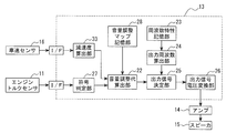
- FIG. 9 is a system configuration diagram of a deceleration information transmission apparatus showing an application example 2.
- the engine torque sensor 11 and the sign determination unit 27 described above are added.
- the sound volume adjustment coefficient kt is calculated according to the engine torque Te
- the sound volume adjustment coefficient kg is calculated according to the deceleration G
- the final output is obtained by using the product or sum of these sound volume adjustment coefficients kt and kg.
- a signal may be generated.
- the weights of the volume adjustment coefficients kt and kg may be the same (1: 1 relationship), or different weights may be used.
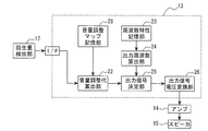
- FIG. 10 is a system configuration diagram of the deceleration information transmission apparatus showing the fifth embodiment.
- a regeneration amount detection unit 17 a control unit 13 configured by, for example, a microcomputer, an amplifier 14, and a speaker 15 are provided.
- the control unit 13 corresponds to a “deceleration information setting unit”
- the speaker 15 corresponds to a “transmission unit”.
- the regenerative amount detection unit 17 detects, for example, a target deceleration, a regenerative torque command value, etc. in the regenerative brake as the regenerative amount B.
- the regeneration amount detection unit 17 corresponds to a “regeneration amount detection unit”.
- the control unit 13 includes a volume adjustment map storage unit 28, a volume adjustment allowance calculation unit 22, a frequency characteristic storage unit 23, an output frequency calculation unit 24, an output signal determination unit 25, an output signal voltage conversion unit 26, Is provided.
- the control unit 13 executes a deceleration state transmission control process and transmits to the driver a sound in which the volume changes according to the deceleration state (the driver's intention to decelerate or the vehicle's deceleration state) in real time. To do. That is, with reference to the map of FIG. 11, adjustment is performed using the volume adjustment coefficient kb determined according to the regeneration amount B.
- FIG. 11 is a map used for calculating the volume adjustment coefficient kb.
- the volume adjustment coefficient kb increases as the regeneration amount B increases.
- the characteristic line has an inverted S shape. That is, the increase rate of the volume adjustment coefficient kb with respect to the regeneration amount B is set so that the increase rate is small in the region where the regeneration amount B is small and large and the increase rate is large in the intermediate region.
- At least one of the driver's intention to decelerate and the vehicle's decelerating state is transmitted to the driver by sound volume as a deceleration state.
- the volume adjustment coefficient kb is calculated according to the regeneration amount B, and the volume is adjusted according to the volume adjustment coefficient kb.
- the regeneration amount B correlated with the deceleration of the vehicle is detected, and the transmission degree of the deceleration state is adjusted according to the regeneration amount B. The situation during deceleration such as can be transmitted more accurately.
- the regeneration amount detection unit 17 corresponds to the “regeneration amount detection unit”.
- the regeneration amount B of the regenerative brake is calculated, and the volume of the deceleration sound is adjusted according to the regeneration amount B and transmitted to the driver.
- the degree of transmission of the deceleration situation is adjusted according to the regeneration amount B, the deceleration situation such as the driver's intention to decelerate and the deceleration state of the vehicle can be more accurately transmitted.
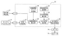
- FIG. 12 is a system configuration diagram of a deceleration information transmission apparatus showing an application example 1.
- the engine torque sensor 11 and the sign determination unit 27 described above are added.
- the sound volume adjustment coefficient kt is calculated according to the engine torque Te
- the sound volume adjustment coefficient kb is calculated according to the regeneration amount B
- the final output is obtained using the product or sum of the sound volume adjustment coefficients kt and kb.
- a signal may be generated.
- the volume adjustment coefficients kt and kb may have the same weight (a 1: 1 relationship), or may have different weights.
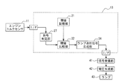
- FIG. 13 is a system configuration diagram of the deceleration information transmission apparatus showing the sixth embodiment.
- the engine torque sensor 11, a control unit 13 configured by, for example, a microcomputer, a signal reception unit 41, a voltage generation unit 42, and a lamp 43 are provided.
- the engine torque sensor 11 corresponds to a “drive torque detection unit”
- the control unit 13 corresponds to a “deceleration information setting unit”
- the lamp 43 corresponds to a “transmission unit”.
- the lamp 43 is provided at a position that is visible to the driver.
- the control unit 13 includes a volume adjustment map storage unit 28, a threshold storage unit 31, a threshold comparison unit 32, and a lamp lighting signal generation unit 34.
- the control unit 13 executes a deceleration state transmission control process, and transmits it to the driver by turning on the lamp 43 according to the deceleration state (the driver's intention to decelerate or the vehicle's deceleration state). That is, the lamp 43 is turned on when the engine torque Te exceeds the threshold th.
- the deceleration state can be transmitted to the driver by lighting the lamp 43, that is, by display. Therefore, the driver can visually recognize the situation during deceleration even in a driving scene where it is difficult to hear sound due to the influence outside the vehicle or the influence from the road surface.
- the lamp 43 corresponds to the “transmitting unit”.
- the deceleration information transmission device the deceleration information is transmitted to the driver by turning on the lamp 43. Thereby, deceleration information can be easily transmitted to the driver. In addition, even in a driving scene where it is difficult to hear sound due to the influence from outside the vehicle or the road surface, the driver can visually recognize the situation during deceleration.
- FIG. 14 is a system configuration diagram of the deceleration information transmission apparatus showing the seventh embodiment.
- the engine torque sensor 11, a control unit 13 configured by, for example, a microcomputer, a signal receiving unit 51, a vibration exciter 52, and a lamp 53 are provided.
- the engine torque sensor 11 corresponds to a “drive torque detection unit”
- the control unit 13 corresponds to a “deceleration information setting unit”
- the shaker 52 and the lamp 53 correspond to a “transmission unit”.
- the vibration exciter 52 is provided on the steering wheel.
- the lamp 53 is provided at a position that is visible to the driver.
- the control unit 13 includes a volume adjustment map storage unit 28, a threshold storage unit 31, a threshold comparison unit 32, and a vibration signal generation unit 35.
- the control unit 13 executes a deceleration state transmission control process, vibrates the vibration exciter 52 according to the deceleration state (the driver's intention to decelerate or the vehicle's deceleration state), and turns on the lamp 53. Communicate to the driver. That is, when the engine torque Te exceeds the threshold th, the shaker 52 is vibrated and the lamp 53 is turned on.
- the deceleration state can be transmitted to the driver by the vibration of the shaker 52 and the lighting of the lamp 53. Therefore, the driver can recognize the deceleration state by tactile sensation and vision even in a driving scene where it is difficult to hear sound due to the influence outside the vehicle or the influence from the road surface. From the above, the vibration exciter 52 and the lamp 53 correspond to the “transmission unit”.
- the deceleration information transmission device the deceleration information is transmitted to the driver by vibrating the vibrator 52. Thereby, deceleration information can be easily transmitted to the driver. In addition, even in a driving scene where it is difficult to hear sound due to the influence from outside the vehicle or the road surface, the driver can visually recognize the situation during deceleration.
- Japanese Patent Application P2011-119614 filed on May 27, 2011 to which the present application claims priority are included herein as reference examples.
- Engine torque sensor 13 Control unit 14 Amplifier 15 Speaker 16 Vehicle speed sensor 17 Regeneration amount detection unit 21 Volume adjustment primary expression storage unit 22 Volume adjustment allowance calculation unit 23 Frequency characteristic storage unit 24 Output frequency calculation unit 25 Output signal determination unit 26 Output signal Voltage conversion unit 27 Code determination unit 28 Volume adjustment map storage unit 31 Threshold storage unit 32 Threshold comparison unit 33 Deceleration calculation unit 34 Lamp lighting signal generation unit 35 Vibration signal generation unit 41 Signal reception unit 42 Voltage generation unit 43 Lamp 51 Signal reception Part 52 Exciter 53 Lamp
Landscapes
- Engineering & Computer Science (AREA)
- Automation & Control Theory (AREA)
- Mechanical Engineering (AREA)
- Human Computer Interaction (AREA)
- Transportation (AREA)
- Physics & Mathematics (AREA)
- General Physics & Mathematics (AREA)
- Circuit For Audible Band Transducer (AREA)
- Control Of Vehicle Engines Or Engines For Specific Uses (AREA)
- Hybrid Electric Vehicles (AREA)
- Control Of Transmission Device (AREA)
- Fittings On The Vehicle Exterior For Carrying Loads, And Devices For Holding Or Mounting Articles (AREA)
Abstract
車両の減速情報をより正確に伝達することを目的とする。エンジントルクTeが負値であるときに、このエンジントルクTeに応じて音量調整係数ktを算出し、この音量調整係数ktに応じて音量を調整する。音量調整係数ktは、エンジントルクTeの絶対値が大きいほど、大きい値になるように設定してある。
Description
本発明は、減速情報伝達装置、減速情報伝達方法に関するものである。
特許文献1の従来技術では、エンジンの回転周波数に応じて効果音の音圧を調整しており、回転周波数の単位時間当たり変化量が予め定められた値を超えたときには、効果音の出力を中止している。
上記従来技術のように、回転周波数の単位時間当たりの変化量に基づいて効果音の出力を中止すると、運転者の減速意図や車両の減速状態などの減速時状況を運転者に正確に伝達することが難しい。
本発明の課題は、運転者の減速意図や車両の減速状態などの減速時状況をより正確に伝達することである。
本発明の課題は、運転者の減速意図や車両の減速状態などの減速時状況をより正確に伝達することである。
本発明の一態様に係る車両用減速度制御装置は、回転駆動源の駆動トルクを検出し、この駆動トルクが負値であるときに、この駆動トルクに応じて、運転者の減速意図及び車両の減速状態の少なくとも一方を表す減速情報を設定し、設定した減速情報を運転者に伝達する。
本発明の一態様に係る車両用減速度制御装置によれば、負値となる駆動トルクに応じて、減速時状況の伝達度合を調整しているので、運転者の減速意図や車両の減速状態などの減速時状況をより正確に伝達することができる。
以下、本発明の実施形態を図面に基づいて説明する。
《第1実施形態》
《構成》
図1は、減速情報伝達装置のシステム構成図である。
本実施形態では、エンジントルクTeを検出するエンジントルクセンサ11と、例えばマイクロコンピュータで構成されたコントロールユニット13と、アンプ14と、スピーカ15と、を備える。ここで、エンジントルクセンサ11が「駆動トルク検出部」に対応し、コントロールユニット13が「減速情報設定部」に対応し、スピーカ15が「伝達部」に対応する。
《第1実施形態》
《構成》
図1は、減速情報伝達装置のシステム構成図である。
本実施形態では、エンジントルクTeを検出するエンジントルクセンサ11と、例えばマイクロコンピュータで構成されたコントロールユニット13と、アンプ14と、スピーカ15と、を備える。ここで、エンジントルクセンサ11が「駆動トルク検出部」に対応し、コントロールユニット13が「減速情報設定部」に対応し、スピーカ15が「伝達部」に対応する。
なお、エンジントルクセンサ11の代わりに、CAN通信によってエンジントルクTeを取得したり、エンジン回転数、変速比、車速等に基づいてエンジントルクTeを算出したりしてもよい。
また、回転駆動源がエンジンである場合について説明しているが、ハイブリッド車両(HEV)においてモータ走行している場合や、電気自動車(EV)の場合には、回転駆動源の駆動トルクとしてモータトルクを検出する。
また、回転駆動源がエンジンである場合について説明しているが、ハイブリッド車両(HEV)においてモータ走行している場合や、電気自動車(EV)の場合には、回転駆動源の駆動トルクとしてモータトルクを検出する。
コントロールユニット13は、音量調整一次式記憶部21と、音量調整代算出部22と、周波数特性記憶部23と、出力周波数算出部24と、出力信号決定部25と、出力信号電圧変換部26と、符号判定部27と、を備える。
コントロールユニット13は、減速時状況伝達制御処理を実行し、減速時状況(運転者の減速意図や車両の減速状態)に応じて音量が変わる音をリアルタイムにドライバに聞かせることで、ドライバに伝達する。音量はエンジントルクTeを表す信号を得て、エンジントルクが負値となるときに、そのエンジントルクTeに応じて決められた音量調整係数ktを用いて調整する。
コントロールユニット13は、減速時状況伝達制御処理を実行し、減速時状況(運転者の減速意図や車両の減速状態)に応じて音量が変わる音をリアルタイムにドライバに聞かせることで、ドライバに伝達する。音量はエンジントルクTeを表す信号を得て、エンジントルクが負値となるときに、そのエンジントルクTeに応じて決められた音量調整係数ktを用いて調整する。
次に、コントロールユニット13で所定時間(例えば10msec)毎に実行される減速時状況伝達制御処理について説明する。
図2は、減速時状況伝達制御処理を示すフローチャートである。
先ずステップS11では、エンジントルクTeを読込む。
続くステップS12は、符号判定部27での処理に対応し、エンジントルクTeが負値であるか否かを判定する。判定結果が『Te≧0』であれば、減速意図や減速状態を表す減速情報は不要であると判断し、そのまま所定のメインプログラムに復帰する。一方、判定結果が『Te<0』であれば、減速情報を運転者に伝達するためにステップS13に移行する。
図2は、減速時状況伝達制御処理を示すフローチャートである。
先ずステップS11では、エンジントルクTeを読込む。
続くステップS12は、符号判定部27での処理に対応し、エンジントルクTeが負値であるか否かを判定する。判定結果が『Te≧0』であれば、減速意図や減速状態を表す減速情報は不要であると判断し、そのまま所定のメインプログラムに復帰する。一方、判定結果が『Te<0』であれば、減速情報を運転者に伝達するためにステップS13に移行する。
続くステップS13は、音量調整代算出部22での処理に対応し、音量調整一次式記憶部21に記憶された音量調整一次式により、エンジントルクTeに応じた音量調整係数ktを算出する。音量調整一次式は、エンジントルクTeの絶対値が大きいほど(負側に大きいほど)、音量調整係数ktが大きくなるように設定してある。
続くステップS14は、出力周波数算出部24での処理に対応し、音源データからエンジントルクの次数成分に応じた音色(減速音)を設定する。
続くステップS14は、出力周波数算出部24での処理に対応し、音源データからエンジントルクの次数成分に応じた音色(減速音)を設定する。
音源データは、コントロールユニット13の周波数特性記憶部23に予め記憶されたwavファイルやmidiファイル等である。この音源データは、USB等の外部端子による変更及びプリセットされたファイルをセレクトでき、書き換え可能とする。
続くステップS15は、出力信号決定部25での処理に対応し、音量調整係数kt、エンジントルクの次数成分に応じた音色に応じて出力信号を生成する。
続くステップS16は、出力信号電圧変換部26での処理に対応し、出力信号を電圧変換し、アンプ14へ出力し、スピーカ15を介して減速音を出力する。
続くステップS15は、出力信号決定部25での処理に対応し、音量調整係数kt、エンジントルクの次数成分に応じた音色に応じて出力信号を生成する。
続くステップS16は、出力信号電圧変換部26での処理に対応し、出力信号を電圧変換し、アンプ14へ出力し、スピーカ15を介して減速音を出力する。
《作用》
運転者の減速意図及び車両の減速状態の少なくとも一方を、減速時状況として、音量でドライバに伝達する。
具体的には、エンジントルクTeが負値となるときに(S12の判定が“Yes”)、エンジントルクTeに応じて音量調整係数ktを算出し(S13)、この音量調整係数ktに応じて音量が調整した減速音を出力する(S14~S16)。
このように、負値となるエンジントルクTeに応じて、減速時状況の伝達度合を調整しているので、運転者の減速意図や車両の減速状態などの減速時状況をより正確に伝達することができる。
運転者の減速意図及び車両の減速状態の少なくとも一方を、減速時状況として、音量でドライバに伝達する。
具体的には、エンジントルクTeが負値となるときに(S12の判定が“Yes”)、エンジントルクTeに応じて音量調整係数ktを算出し(S13)、この音量調整係数ktに応じて音量が調整した減速音を出力する(S14~S16)。
このように、負値となるエンジントルクTeに応じて、減速時状況の伝達度合を調整しているので、運転者の減速意図や車両の減速状態などの減速時状況をより正確に伝達することができる。
すなわち、エンジンブレーキによる減速時、エンジントルクTeは負値となり、値の絶対値が大きいほどエンジンブレーキによる減速度が大きくなる。そこで、エンジントルクTeの情報をリアルタイムで取得し、エンジントルクTeが負値のときに、エンジントルクTeの絶対値が大きいほど、減速音を大きくする。このように、エンジンブレーキによる減速度と相関があるエンジントルクTeで音量を制御することにより、車両の減速に対して、より適切な音量に制御することができる。
以上より、エンジントルクセンサ11が「駆動トルク検出部」に対応し、コントロールユニット13が「減速情報設定部」に対応し、スピーカ15が「伝達部」に対応する。
以上より、エンジントルクセンサ11が「駆動トルク検出部」に対応し、コントロールユニット13が「減速情報設定部」に対応し、スピーカ15が「伝達部」に対応する。
《効果》
(1)減速情報伝達装置によれば、エンジントルクTeが負値であるときに、このエンジントルクTeに応じて、減速音の音量を調整し、運転者に伝達する。
このように、負値となるエンジントルクTeに応じて、減速時状況の伝達度合を調整しているので、運転者の減速意図や車両の減速状態などの減速時状況をより正確に伝達することができる。
(1)減速情報伝達装置によれば、エンジントルクTeが負値であるときに、このエンジントルクTeに応じて、減速音の音量を調整し、運転者に伝達する。
このように、負値となるエンジントルクTeに応じて、減速時状況の伝達度合を調整しているので、運転者の減速意図や車両の減速状態などの減速時状況をより正確に伝達することができる。
(2)減速情報伝達装置によれば、スピーカ15を介して減速音を出力することにより、減速情報を運転者に伝達する。
これにより、運転者に対して容易に減速情報を伝達することができる。
(3)減速情報伝達方法によれば、エンジントルクTeが負値であるときに、このエンジントルクTeに応じて、減速音の音量を調整し、運転者に伝達する。
このように、負値となるエンジントルクTeに応じて、減速時状況の伝達度合を調整しているので、運転者の減速意図や車両の減速状態などの減速時状況をより正確に伝達することができる。
これにより、運転者に対して容易に減速情報を伝達することができる。
(3)減速情報伝達方法によれば、エンジントルクTeが負値であるときに、このエンジントルクTeに応じて、減速音の音量を調整し、運転者に伝達する。
このように、負値となるエンジントルクTeに応じて、減速時状況の伝達度合を調整しているので、運転者の減速意図や車両の減速状態などの減速時状況をより正確に伝達することができる。
《第2実施形態》
《構成》
本実施形態は、音量調整係数ktを算出する際、前述した音量調整一次式の代わりに、マップを参照するものである。
図3は、第2実施形態を示す減速情報伝達装置のシステム構成図である。
コントロールユニット13は、音量調整マップ記憶部28と、音量調整代算出部22と、周波数特性記憶部23と、出力周波数算出部24と、出力信号決定部25と、出力信号電圧変換部26と、符号判定部27と、を備える。
《構成》
本実施形態は、音量調整係数ktを算出する際、前述した音量調整一次式の代わりに、マップを参照するものである。
図3は、第2実施形態を示す減速情報伝達装置のシステム構成図である。
コントロールユニット13は、音量調整マップ記憶部28と、音量調整代算出部22と、周波数特性記憶部23と、出力周波数算出部24と、出力信号決定部25と、出力信号電圧変換部26と、符号判定部27と、を備える。
図4は、音量調整係数ktの算出に用いるマップである。
このマップによれば、エンジントルクTeが負側に大きいほど、音量調整係数ktが大きくなる。その特性線は逆S字状である。すなわち、エンジントルクTeに対する音量調整係数ktの増加率は、エンジントルクTeの絶対値が小さい領域と大きい領域では増加率が小さく、その中間の領域では増加率が大きくなるように設定してある。
このマップによれば、エンジントルクTeが負側に大きいほど、音量調整係数ktが大きくなる。その特性線は逆S字状である。すなわち、エンジントルクTeに対する音量調整係数ktの増加率は、エンジントルクTeの絶対値が小さい領域と大きい領域では増加率が小さく、その中間の領域では増加率が大きくなるように設定してある。
《作用》
エンジントルクTeが負値となるときに(S12の判定が“Yes”)、図4のマップを参照し、エンジントルクTeに応じて音量調整係数ktを算出し(S13)、この音量調整係数ktに応じて音量を調整する。
このように、負値となるエンジントルクTeに応じて、減速時状況の伝達度合を調整しているので、運転者の減速意図や車両の減速状態などの減速時状況をより正確に伝達することができる。
エンジントルクTeが負値となるときに(S12の判定が“Yes”)、図4のマップを参照し、エンジントルクTeに応じて音量調整係数ktを算出し(S13)、この音量調整係数ktに応じて音量を調整する。
このように、負値となるエンジントルクTeに応じて、減速時状況の伝達度合を調整しているので、運転者の減速意図や車両の減速状態などの減速時状況をより正確に伝達することができる。
また、マップ制御にすることで、自由度を持った音量制御を行うことができる。すなわち、暗騒音やその車両のエンジンやトランスミッションの状態に合わせて音量調整可能となり、自由度が上がる。さらに、特性線を逆S字状にすることで、減速度が徐々に強まってきたとき、つまり速度低下率が高まり減速していることを知る必要のあるときに、その減速音を効果的に運転者に伝達することができる。
《効果》
(1)減速情報伝達装置によれば、エンジントルクTeに応じて、音量調整係数ktが定まるマップを参照する。
このように、マップ制御とすることにより、自由度を持った音量制御を容易に行うことができる。
(1)減速情報伝達装置によれば、エンジントルクTeに応じて、音量調整係数ktが定まるマップを参照する。
このように、マップ制御とすることにより、自由度を持った音量制御を容易に行うことができる。
《第3実施形態》
《構成》
本実施形態は、エンジントルクTeの絶対値が閾値thより大きいときに、減速音の音量調整を行うものである。
図5は、第3実施形態を示す減速情報伝達装置のシステム構成図である。
コントロールユニット13は、閾値記憶部31と、閾値比較部32と、周波数特性記憶部23と、出力周波数算出部24と、出力信号決定部25と、出力信号電圧変換部26と、符号判定部27と、を備える。
《構成》
本実施形態は、エンジントルクTeの絶対値が閾値thより大きいときに、減速音の音量調整を行うものである。
図5は、第3実施形態を示す減速情報伝達装置のシステム構成図である。
コントロールユニット13は、閾値記憶部31と、閾値比較部32と、周波数特性記憶部23と、出力周波数算出部24と、出力信号決定部25と、出力信号電圧変換部26と、符号判定部27と、を備える。
図6は、第3実施形態を示す減速時状況伝達制御処理を示すフローチャートである。
先ずステップS31では、エンジントルクTeを読込む。
続くステップS32は、符号判定部27での処理に対応し、エンジントルクTeが負値であるか否かを判定する。判定結果が『Te≧0』であれば、減速意図や減速状態を表す減速情報は不要であると判断し、そのまま所定のメインプログラムに復帰する。一方、判定結果が『Te<0』であれば、ステップS33に移行する。
先ずステップS31では、エンジントルクTeを読込む。
続くステップS32は、符号判定部27での処理に対応し、エンジントルクTeが負値であるか否かを判定する。判定結果が『Te≧0』であれば、減速意図や減速状態を表す減速情報は不要であると判断し、そのまま所定のメインプログラムに復帰する。一方、判定結果が『Te<0』であれば、ステップS33に移行する。
続くステップS33は、閾値比較部32での処理に対応し、閾値記憶部31に予め記憶された閾値thを参照し、エンジントルクTeの絶対値が閾値thよりも大きいか否かを判定する。判定結果が『|Te|≦th』であれば、減速意図や減速状態を表す減速情報は不要であると判断し、そのまま所定のメインプログラムに復帰する。一方、判定結果が『|Te|>th』であれば、減速意図や減速状態を表す減速情報を運転者に伝達するためにステップS34に移行する。
ステップS34は、出力周波数算出部24での処理に対応し、音源データからエンジントルクの次数成分に応じた音色(減速音)を設定する。
音源データは、コントロールユニット13の周波数特性記憶部23に予め記憶されたwavファイルやmidiファイル等である。この音源データは、USB等の外部端子による変更及びプリセットされたファイルをセレクトでき、書き換え可能とする。
音源データは、コントロールユニット13の周波数特性記憶部23に予め記憶されたwavファイルやmidiファイル等である。この音源データは、USB等の外部端子による変更及びプリセットされたファイルをセレクトでき、書き換え可能とする。
続くステップS35では、出力信号決定部25での処理に対応し、エンジントルクの次数成分に応じた音色に応じて出力信号を生成する。
続くステップS36では、出力信号電圧変換部26での処理に対応し、出力信号を電圧変換し、アンプ14へ出力し、スピーカ15を介して減速音を出力する。
続くステップS36では、出力信号電圧変換部26での処理に対応し、出力信号を電圧変換し、アンプ14へ出力し、スピーカ15を介して減速音を出力する。
《作用》
エンジントルクTeが負値となり(S32の判定が“Yes”)、且つエンジントルクTeの絶対値が閾値thを超えたときに(S33の判定が“Yes”)、減速音を出力する(S34~S36)。
このように、負値となるエンジントルクTeに応じて、減速時状況の伝達度合を調整しているので、運転者の減速意図や車両の減速状態などの減速時状況をより正確に伝達することができる。
エンジントルクTeが負値となり(S32の判定が“Yes”)、且つエンジントルクTeの絶対値が閾値thを超えたときに(S33の判定が“Yes”)、減速音を出力する(S34~S36)。
このように、負値となるエンジントルクTeに応じて、減速時状況の伝達度合を調整しているので、運転者の減速意図や車両の減速状態などの減速時状況をより正確に伝達することができる。
また、負値となるエンジントルクTeに対する閾値thを設定し、エンジントルクの絶対値|Te|が閾値thを超えたときに、減速音を出力する。これをリアルタイムで行う。これにより、音で減速情報を知らせるという機能を維持したまま、減速音のON/OFFを切り替えることができるので、制御ロジックを簡略化することができる。
《効果》
(1)エンジントルクTeが負値となり(S32の判定が“Yes”)、且つエンジントルクTeの絶対値が閾値thを超えたときに(S33の判定が“Yes”)、減速情報を運転者に伝達する。
このように、エンジントルクの絶対値|Te|が閾値thを超えたときに、減速音を出力することで、音で減速情報を伝達するという機能を維持したまま、制御ロジックを簡素化することができる。
(1)エンジントルクTeが負値となり(S32の判定が“Yes”)、且つエンジントルクTeの絶対値が閾値thを超えたときに(S33の判定が“Yes”)、減速情報を運転者に伝達する。
このように、エンジントルクの絶対値|Te|が閾値thを超えたときに、減速音を出力することで、音で減速情報を伝達するという機能を維持したまま、制御ロジックを簡素化することができる。
《第4実施形態》
《構成》
本実施形態は、車両の減速度に応じて、減速時状況の伝達度合を調整するものである。
図7は、第4実施形態を示す減速情報伝達装置のシステム構成図である。
本実施形態では、車速センサ16と、例えばマイクロコンピュータで構成されたコントロールユニット13と、アンプ14と、スピーカ15と、を備える。ここで、コントロールユニット13が「減速情報設定部」に対応し、スピーカ15が「伝達部」に対応する。
コントロールユニット13は、減速度算出部33と、音量調整マップ記憶部28と、音量調整代算出部22と、周波数特性記憶部23と、出力周波数算出部24と、出力信号決定部25と、出力信号電圧変換部26と、を備える。ここで、減速度算出部33が「減速度検出部」に対応する。
《構成》
本実施形態は、車両の減速度に応じて、減速時状況の伝達度合を調整するものである。
図7は、第4実施形態を示す減速情報伝達装置のシステム構成図である。
本実施形態では、車速センサ16と、例えばマイクロコンピュータで構成されたコントロールユニット13と、アンプ14と、スピーカ15と、を備える。ここで、コントロールユニット13が「減速情報設定部」に対応し、スピーカ15が「伝達部」に対応する。
コントロールユニット13は、減速度算出部33と、音量調整マップ記憶部28と、音量調整代算出部22と、周波数特性記憶部23と、出力周波数算出部24と、出力信号決定部25と、出力信号電圧変換部26と、を備える。ここで、減速度算出部33が「減速度検出部」に対応する。
コントロールユニット13は、減速時状況伝達制御処理を実行し、減速時状況(運転者の減速意図や車両の減速状態)に応じて音量が変わる音をリアルタイムにドライバに聞かせることで、ドライバに伝達する。すなわち、車速の単位時間値の変化量(例えば微分値)に基づいて減速度Gを算出し、図8のマップを参照し、減速度Gに応じて決められた音量調整係数kgを用いて調整する。
図8は、音量調整係数kgの算出に用いるマップである。
このマップによれば、減速度Gが大きいほど、音量調整係数ktが大きくなる。その特性線は逆S字状である。すなわち、減速度Gに対する音量調整係数ktの増加率は、減速度Gが小さい領域と大きい領域では増加率が小さく、その中間の領域では増加率が大きくなるように設定してある。
このマップによれば、減速度Gが大きいほど、音量調整係数ktが大きくなる。その特性線は逆S字状である。すなわち、減速度Gに対する音量調整係数ktの増加率は、減速度Gが小さい領域と大きい領域では増加率が小さく、その中間の領域では増加率が大きくなるように設定してある。
《作用》
運転者の減速意図及び車両の減速状態の少なくとも一方を、減速時状況として、音量でドライバに伝達する。具体的には、減速度Gに応じて音量調整係数kgを算出し、この音量調整係数ktに応じて音量を調整する。
このように、減速度Gに応じて、減速時状況の伝達度合を調整しているので、運転者の減速意図や車両の減速状態などの減速時状況をより正確に伝達することができる。
運転者の減速意図及び車両の減速状態の少なくとも一方を、減速時状況として、音量でドライバに伝達する。具体的には、減速度Gに応じて音量調整係数kgを算出し、この音量調整係数ktに応じて音量を調整する。
このように、減速度Gに応じて、減速時状況の伝達度合を調整しているので、運転者の減速意図や車両の減速状態などの減速時状況をより正確に伝達することができる。
すなわち、減速度Gの情報をリアルタイムで取得し、減速度Gが大きいほど、減速音を大きくする。このように、エンジンブレーキに伴う減速度Gで音量を制御することにより、車両の減速度に対して、より適切な音量に制御することができる。
以上より、減速度算出部33が「減速度検出部」に対応する。
以上より、減速度算出部33が「減速度検出部」に対応する。
《効果》
(1)車速に基づいて車両の減速度Gを算出し、この減速度Gに応じて、減速音の音量を調整し、運転者に伝達する。
このように、減速度Gに応じて減速時状況の伝達度合を調整しているので、運転者の減速意図や車両の減速状態などの減速時状況をより正確に伝達することができる。
《応用例1》
本実施形態では、車速センサ16からの信号に基づいて車両の減速度Gを算出しているが、勿論、加速度センサによって直接的に車両の減速度Gを検出してもよい。これによれば、減速度算出部33の処理を省略することができる。
(1)車速に基づいて車両の減速度Gを算出し、この減速度Gに応じて、減速音の音量を調整し、運転者に伝達する。
このように、減速度Gに応じて減速時状況の伝達度合を調整しているので、運転者の減速意図や車両の減速状態などの減速時状況をより正確に伝達することができる。
《応用例1》
本実施形態では、車速センサ16からの信号に基づいて車両の減速度Gを算出しているが、勿論、加速度センサによって直接的に車両の減速度Gを検出してもよい。これによれば、減速度算出部33の処理を省略することができる。
《応用例2》
本実施形態では、減速度Gだけに応じて、減速音の音量を調整しているが、図9に示すように、エンジントルクTe及び減速度Gに応じて、減速音の音量を調整してもよい。
図9は、応用例2を示す減速情報伝達装置のシステム構成図である。
ここでは、前述したエンジントルクセンサ11、及び符号判定部27を追加している。そして、エンジントルクTeに応じて音量調整係数ktを算出すると共に、減速度Gに応じて音量調整係数kgを算出し、これら音量調整係数kt及びkgの積又は和を用いて、最終的な出力信号を生成してもよい。この場合、音量調整係数kt及びkgの重みは同一(1:1の関係)としてもよいし、夫々に異なる重み付けをしてもよい。
本実施形態では、減速度Gだけに応じて、減速音の音量を調整しているが、図9に示すように、エンジントルクTe及び減速度Gに応じて、減速音の音量を調整してもよい。
図9は、応用例2を示す減速情報伝達装置のシステム構成図である。
ここでは、前述したエンジントルクセンサ11、及び符号判定部27を追加している。そして、エンジントルクTeに応じて音量調整係数ktを算出すると共に、減速度Gに応じて音量調整係数kgを算出し、これら音量調整係数kt及びkgの積又は和を用いて、最終的な出力信号を生成してもよい。この場合、音量調整係数kt及びkgの重みは同一(1:1の関係)としてもよいし、夫々に異なる重み付けをしてもよい。
《第5実施形態》
《構成》
本実施形態は、ハイブリッド車両(HEV)や電気車両(EV)における回生ブレーキの回生量に応じて、減速時状況の伝達度合を調整するものである。
図10は、第5実施形態を示す減速情報伝達装置のシステム構成図である。
本実施形態では、回生量検出部17と、例えばマイクロコンピュータで構成されたコントロールユニット13と、アンプ14と、スピーカ15と、を備える。ここで、コントロールユニット13が「減速情報設定部」に対応し、スピーカ15が「伝達部」に対応する。
《構成》
本実施形態は、ハイブリッド車両(HEV)や電気車両(EV)における回生ブレーキの回生量に応じて、減速時状況の伝達度合を調整するものである。
図10は、第5実施形態を示す減速情報伝達装置のシステム構成図である。
本実施形態では、回生量検出部17と、例えばマイクロコンピュータで構成されたコントロールユニット13と、アンプ14と、スピーカ15と、を備える。ここで、コントロールユニット13が「減速情報設定部」に対応し、スピーカ15が「伝達部」に対応する。
回生量検出部17は、回生ブレーキにおける例えば目標減速度や回生トルク指令値等を回生量Bとして検出する。ここで、回生量検出部17が「回生量検出部」に対応する。
コントロールユニット13は、音量調整マップ記憶部28と、音量調整代算出部22と、周波数特性記憶部23と、出力周波数算出部24と、出力信号決定部25と、出力信号電圧変換部26と、を備える。
コントロールユニット13は、減速時状況伝達制御処理を実行し、減速時状況(運転者の減速意図や車両の減速状態)に応じて音量が変わる音をリアルタイムにドライバに聞かせることで、ドライバに伝達する。すなわち、図11のマップを参照し、回生量Bに応じて決められた音量調整係数kbを用いて調整する。
コントロールユニット13は、音量調整マップ記憶部28と、音量調整代算出部22と、周波数特性記憶部23と、出力周波数算出部24と、出力信号決定部25と、出力信号電圧変換部26と、を備える。
コントロールユニット13は、減速時状況伝達制御処理を実行し、減速時状況(運転者の減速意図や車両の減速状態)に応じて音量が変わる音をリアルタイムにドライバに聞かせることで、ドライバに伝達する。すなわち、図11のマップを参照し、回生量Bに応じて決められた音量調整係数kbを用いて調整する。
図11は、音量調整係数kbの算出に用いるマップである。
このマップによれば、回生量Bが大きいほど、音量調整係数kbが大きくなる。その特性線は逆S字状である。すなわち、回生量Bに対する音量調整係数kbの増加率は、回生量Bが小さい領域と大きい領域では増加率が小さく、その中間の領域では増加率が大きくなるように設定してある。
このマップによれば、回生量Bが大きいほど、音量調整係数kbが大きくなる。その特性線は逆S字状である。すなわち、回生量Bに対する音量調整係数kbの増加率は、回生量Bが小さい領域と大きい領域では増加率が小さく、その中間の領域では増加率が大きくなるように設定してある。
《作用》
運転者の減速意図及び車両の減速状態の少なくとも一方を、減速時状況として、音量でドライバに伝達する。具体的には、回生量Bに応じて音量調整係数kbを算出し、この音量調整係数kbに応じて音量を調整する。
このように、車両の減速度と相関のある回生量Bを検出し、この回生量Bに応じて、減速時状況の伝達度合を調整しているので、運転者の減速意図や車両の減速状態などの減速時状況をより正確に伝達することができる。
運転者の減速意図及び車両の減速状態の少なくとも一方を、減速時状況として、音量でドライバに伝達する。具体的には、回生量Bに応じて音量調整係数kbを算出し、この音量調整係数kbに応じて音量を調整する。
このように、車両の減速度と相関のある回生量Bを検出し、この回生量Bに応じて、減速時状況の伝達度合を調整しているので、運転者の減速意図や車両の減速状態などの減速時状況をより正確に伝達することができる。
すなわち、回生量Bの情報をリアルタイムで取得し、回生量Bが大きいほど、減速音を大きくする。このように、回生ブレーキによる回生量で音量を制御することにより、車両の減速時状況に対して、より適切な音量に制御することができる。
また、回生ブレーキシステムの回生量Bを利用しているので、エンジントルクや車速や減速度などを検出するセンサを新たに追加することなく、減速情報を運転者に伝達することができる。
以上より、回生量検出部17が「回生量検出部」に対応する。
また、回生ブレーキシステムの回生量Bを利用しているので、エンジントルクや車速や減速度などを検出するセンサを新たに追加することなく、減速情報を運転者に伝達することができる。
以上より、回生量検出部17が「回生量検出部」に対応する。
《効果》
(1)回生ブレーキの回生量Bを算出し、この回生量Bに応じて、減速音の音量を調整し、運転者に伝達する。
このように、回生量Bに応じて減速時状況の伝達度合を調整しているので、運転者の減速意図や車両の減速状態などの減速時状況をより正確に伝達することができる。
(1)回生ブレーキの回生量Bを算出し、この回生量Bに応じて、減速音の音量を調整し、運転者に伝達する。
このように、回生量Bに応じて減速時状況の伝達度合を調整しているので、運転者の減速意図や車両の減速状態などの減速時状況をより正確に伝達することができる。
《応用例1》
本実施形態では、回生量Bだけに応じて、減速音の音量を調整しているが、図12に示すように、エンジントルクTe及び回生量Bに応じて、減速音の音量を調整してもよい。
図12は、応用例1を示す減速情報伝達装置のシステム構成図である。
ここでは、前述したエンジントルクセンサ11、及び符号判定部27を追加している。そして、エンジントルクTeに応じて音量調整係数ktを算出すると共に、回生量Bに応じて音量調整係数kbを算出し、これら音量調整係数kt及びkbの積又は和を用いて、最終的な出力信号を生成してもよい。この場合、音量調整係数kt及びkbの重みは同一(1:1の関係)としてもよいし、夫々に異なる重み付けをしてもよい。
本実施形態では、回生量Bだけに応じて、減速音の音量を調整しているが、図12に示すように、エンジントルクTe及び回生量Bに応じて、減速音の音量を調整してもよい。
図12は、応用例1を示す減速情報伝達装置のシステム構成図である。
ここでは、前述したエンジントルクセンサ11、及び符号判定部27を追加している。そして、エンジントルクTeに応じて音量調整係数ktを算出すると共に、回生量Bに応じて音量調整係数kbを算出し、これら音量調整係数kt及びkbの積又は和を用いて、最終的な出力信号を生成してもよい。この場合、音量調整係数kt及びkbの重みは同一(1:1の関係)としてもよいし、夫々に異なる重み付けをしてもよい。
《第6実施形態》
《構成》
本実施形態は、ランプを介して減速状態を運転者に伝達するものである。
図13は、第6実施形態を示す減速情報伝達装置のシステム構成図である。
本実施形態では、エンジントルクセンサ11と、例えばマイクロコンピュータで構成されたコントロールユニット13と、信号受信部41と、電圧生成部42と、ランプ43と、を備える。ここで、エンジントルクセンサ11が「駆動トルク検出部」に対応し、コントロールユニット13が「減速情報設定部」に対応し、ランプ43が「伝達部」に対応する。
《構成》
本実施形態は、ランプを介して減速状態を運転者に伝達するものである。
図13は、第6実施形態を示す減速情報伝達装置のシステム構成図である。
本実施形態では、エンジントルクセンサ11と、例えばマイクロコンピュータで構成されたコントロールユニット13と、信号受信部41と、電圧生成部42と、ランプ43と、を備える。ここで、エンジントルクセンサ11が「駆動トルク検出部」に対応し、コントロールユニット13が「減速情報設定部」に対応し、ランプ43が「伝達部」に対応する。
ランプ43は、運転者から視認可能な位置に設けてある。
コントロールユニット13は、音量調整マップ記憶部28と、閾値記憶部31と、閾値比較部32と、ランプ点灯信号生成部34と、を備える。
コントロールユニット13は、減速時状況伝達制御処理を実行し、減速時状況(運転者の減速意図や車両の減速状態)に応じてランプ43を点灯させることで、ドライバに伝達する。すなわち、エンジントルクTeが閾値thを超えたときに、ランプ43を点灯する。
コントロールユニット13は、音量調整マップ記憶部28と、閾値記憶部31と、閾値比較部32と、ランプ点灯信号生成部34と、を備える。
コントロールユニット13は、減速時状況伝達制御処理を実行し、減速時状況(運転者の減速意図や車両の減速状態)に応じてランプ43を点灯させることで、ドライバに伝達する。すなわち、エンジントルクTeが閾値thを超えたときに、ランプ43を点灯する。
《作用》
本実施形態では、ランプ43の点灯によって、つまり表示によって減速時状況を運転者に伝達することができる。したがって、車外の影響や路面からの影響によって、音が聞こえにくい走行シーンでも、減速時状況を視覚によって運転者が認識できる。
以上より、ランプ43が「伝達部」に対応する。
本実施形態では、ランプ43の点灯によって、つまり表示によって減速時状況を運転者に伝達することができる。したがって、車外の影響や路面からの影響によって、音が聞こえにくい走行シーンでも、減速時状況を視覚によって運転者が認識できる。
以上より、ランプ43が「伝達部」に対応する。
《効果》
(1)減速情報伝達装置によれば、ランプ43を点灯することにより、減速情報を運転者に伝達する。
これにより、運転者に対して容易に減速情報を伝達することができる。また、車外の影響や路面からの影響によって、音が聞こえにくい走行シーンでも、減速時状況を視覚によって運転者が認識できる。
(1)減速情報伝達装置によれば、ランプ43を点灯することにより、減速情報を運転者に伝達する。
これにより、運転者に対して容易に減速情報を伝達することができる。また、車外の影響や路面からの影響によって、音が聞こえにくい走行シーンでも、減速時状況を視覚によって運転者が認識できる。
《第7実施形態》
《構成》
本実施形態は、加振機を介して減速状態を運転者に伝達するものである。
図14は、第7実施形態を示す減速情報伝達装置のシステム構成図である。
本実施形態では、エンジントルクセンサ11と、例えばマイクロコンピュータで構成されたコントロールユニット13と、信号受信部51と、加振機52と、ランプ53と、を備える。ここで、エンジントルクセンサ11が「駆動トルク検出部」に対応し、コントロールユニット13が「減速情報設定部」に対応し、加振機52及びランプ53が「伝達部」に対応する。
《構成》
本実施形態は、加振機を介して減速状態を運転者に伝達するものである。
図14は、第7実施形態を示す減速情報伝達装置のシステム構成図である。
本実施形態では、エンジントルクセンサ11と、例えばマイクロコンピュータで構成されたコントロールユニット13と、信号受信部51と、加振機52と、ランプ53と、を備える。ここで、エンジントルクセンサ11が「駆動トルク検出部」に対応し、コントロールユニット13が「減速情報設定部」に対応し、加振機52及びランプ53が「伝達部」に対応する。
加振機52は、ステアリングホイールに設けている。
ランプ53は、運転者から視認可能な位置に設けてある。
コントロールユニット13は、音量調整マップ記憶部28と、閾値記憶部31と、閾値比較部32と、振動信号生成部35と、を備える。
コントロールユニット13は、減速時状況伝達制御処理を実行し、減速時状況(運転者の減速意図や車両の減速状態)に応じて加振機52を振動させると共に、ランプ53を点灯させることで、ドライバに伝達する。すなわち、エンジントルクTeが閾値thを超えたときに、加振機52を振動させると共に、ランプ53を点灯する。
ランプ53は、運転者から視認可能な位置に設けてある。
コントロールユニット13は、音量調整マップ記憶部28と、閾値記憶部31と、閾値比較部32と、振動信号生成部35と、を備える。
コントロールユニット13は、減速時状況伝達制御処理を実行し、減速時状況(運転者の減速意図や車両の減速状態)に応じて加振機52を振動させると共に、ランプ53を点灯させることで、ドライバに伝達する。すなわち、エンジントルクTeが閾値thを超えたときに、加振機52を振動させると共に、ランプ53を点灯する。
《作用》
本実施形態では、加振機52の振動とランプ53の点灯によって、減速時状況を運転者に伝達することができる。したがって、車外の影響や路面からの影響によって、音が聞こえにくい走行シーンでも、減速時状況を触覚と視覚によって運転者が認識できる。
以上より、加振機52及びランプ53が「伝達部」に対応する。
本実施形態では、加振機52の振動とランプ53の点灯によって、減速時状況を運転者に伝達することができる。したがって、車外の影響や路面からの影響によって、音が聞こえにくい走行シーンでも、減速時状況を触覚と視覚によって運転者が認識できる。
以上より、加振機52及びランプ53が「伝達部」に対応する。
《効果》
(1)減速情報伝達装置によれば、加振機52を振動させることにより、減速情報を運転者に伝達する。
これにより、運転者に対して容易に減速情報を伝達することができる。また、車外の影響や路面からの影響によって、音が聞こえにくい走行シーンでも、減速時状況を視覚によって運転者が認識できる。
以上、本願が優先権を主張する日本国特許出願P2011-119614(2011年5月27日出願)の全内容はここに引用例として包含される。
ここでは、限られた数の実施形態を参照しながら説明したが、権利範囲はそれらに限定されるものではなく、上記の開示に基づく各実施形態の改変は当業者にとって自明のことである。
(1)減速情報伝達装置によれば、加振機52を振動させることにより、減速情報を運転者に伝達する。
これにより、運転者に対して容易に減速情報を伝達することができる。また、車外の影響や路面からの影響によって、音が聞こえにくい走行シーンでも、減速時状況を視覚によって運転者が認識できる。
以上、本願が優先権を主張する日本国特許出願P2011-119614(2011年5月27日出願)の全内容はここに引用例として包含される。
ここでは、限られた数の実施形態を参照しながら説明したが、権利範囲はそれらに限定されるものではなく、上記の開示に基づく各実施形態の改変は当業者にとって自明のことである。
11 エンジントルクセンサ
13 コントロールユニット
14 アンプ
15 スピーカ
16 車速センサ
17 回生量検出部
21 音量調整一次式記憶部
22 音量調整代算出部
23 周波数特性記憶部
24 出力周波数算出部
25 出力信号決定部
26 出力信号電圧変換部
27 符号判定部
28 音量調整マップ記憶部
31 閾値記憶部
32 閾値比較部
33 減速度算出部
34 ランプ点灯信号生成部
35 振動信号生成部
41 信号受信部
42 電圧生成部
43 ランプ
51 信号受信部
52 加振機
53 ランプ
13 コントロールユニット
14 アンプ
15 スピーカ
16 車速センサ
17 回生量検出部
21 音量調整一次式記憶部
22 音量調整代算出部
23 周波数特性記憶部
24 出力周波数算出部
25 出力信号決定部
26 出力信号電圧変換部
27 符号判定部
28 音量調整マップ記憶部
31 閾値記憶部
32 閾値比較部
33 減速度算出部
34 ランプ点灯信号生成部
35 振動信号生成部
41 信号受信部
42 電圧生成部
43 ランプ
51 信号受信部
52 加振機
53 ランプ
Claims (11)
- 回転駆動源の駆動トルクを検出する駆動トルク検出部と、
前記駆動トルク検出部で検出した駆動トルクが負値であるときに、前記駆動トルクに応じて、運転者の減速意図及び車両の減速状態の少なくとも一方を表す減速情報を設定する減速情報設定部と、
前記減速情報設定部で設定した減速情報を運転者に伝達する伝達部と、を備えることを特徴とする減速情報伝達装置。 - 前記減速情報設定部は、前記駆動トルク検出部で検出した駆動トルクが負値で、且つ前記駆動トルクの絶対値が、予め定められた閾値よりも大きいときに、前記減速情報を設定することを特徴とする請求項1に記載の減速情報伝達装置。
- 回生ブレーキの回生量を検出する回生量検出部を備え、
前記減速情報設定部は、前記駆動トルク検出部で検出した駆動トルク、及び前記回生量検出部で検出した回生量に応じて、前記減速情報を設定することを特徴とする請求項1に記載の減速情報伝達装置。 - 車両の減速度を検出する減速度検出部を備え、
前記減速情報設定部は、前記駆動トルク検出部で検出した駆動トルク、及び前記減速度検出部で検出した減速度に応じて、前記減速情報を設定することを特徴とする請求項1に記載の減速情報伝達装置。 - 前記伝達部は、スピーカによって減速音を出力することにより、前記減速情報を運転者に伝達することを特徴とする請求項1に記載の減速情報伝達装置。
- 前記伝達部は、表示装置によって減速状態を表示することにより、前記減速情報を運転者に伝達することを特徴とする請求項1に記載の減速情報伝達装置。
- 前記伝達部は、加振機によってステアリング操作子を振動させることにより、前記減速情報を運転者に伝達することを特徴とする請求項1に記載の減速情報伝達装置。
- 前記減速情報設定部は、前記駆動トルク検出部で検出した駆動トルクに応じて、前記減速情報が定まるマップを参照することを特徴とする請求項1に記載の減速情報伝達装置。
- 回生ブレーキの回生量を検出する回生量検出部と、
前記回生量検出部で検出した回生量に応じて、運転者の減速意図及び車両の減速状態の少なくとも一方を表す減速情報を設定する減速情報設定部と、
前記減速情報設定部で設定した減速情報を運転者に伝達する伝達部と、を備えることを特徴とする減速情報伝達装置。 - 車両の減速度を検出する減速度検出部と、
前記減速度検出部で検出した減速度に応じて、運転者の減速意図及び車両の減速状態の少なくとも一方を表す減速情報を設定する減速情報設定部と、
前記減速情報設定部で設定した減速情報を運転者に伝達する伝達部と、を備えることを特徴とする減速情報伝達装置。 - 回転駆動源の駆動トルクを検出し、前記駆動トルクが負値であるときに、前記駆動トルクに応じて、運転者の減速意図及び車両の減速状態の少なくとも一方を表す減速情報を運転者に伝達することを特徴とする減速情報伝達方法。
Priority Applications (3)
| Application Number | Priority Date | Filing Date | Title |
|---|---|---|---|
| EP12793872.8A EP2716501B1 (en) | 2011-05-27 | 2012-02-22 | Deceleration information transmission device and deceleration information transmission method |
| CN201280025357.4A CN103702869B (zh) | 2011-05-27 | 2012-02-22 | 减速信息传递装置、减速信息传递方法 |
| US14/119,579 US9229022B2 (en) | 2011-05-27 | 2012-02-22 | Deceleration information notification device and deceleration information notification method |
Applications Claiming Priority (2)
| Application Number | Priority Date | Filing Date | Title |
|---|---|---|---|
| JP2011119614A JP5170286B2 (ja) | 2011-05-27 | 2011-05-27 | 減速情報伝達装置、減速情報伝達方法 |
| JP2011-119614 | 2011-05-27 |
Publications (1)
| Publication Number | Publication Date |
|---|---|
| WO2012164784A1 true WO2012164784A1 (ja) | 2012-12-06 |
Family
ID=47258663
Family Applications (1)
| Application Number | Title | Priority Date | Filing Date |
|---|---|---|---|
| PCT/JP2012/001187 Ceased WO2012164784A1 (ja) | 2011-05-27 | 2012-02-22 | 減速情報伝達装置、減速情報伝達方法 |
Country Status (5)
| Country | Link |
|---|---|
| US (1) | US9229022B2 (ja) |
| EP (1) | EP2716501B1 (ja) |
| JP (1) | JP5170286B2 (ja) |
| CN (1) | CN103702869B (ja) |
| WO (1) | WO2012164784A1 (ja) |
Families Citing this family (6)
| Publication number | Priority date | Publication date | Assignee | Title |
|---|---|---|---|---|
| JP6186619B2 (ja) * | 2013-12-25 | 2017-08-30 | 三菱自動車工業株式会社 | 電動車両のストップランプ点灯制御装置 |
| JP6186618B2 (ja) * | 2013-12-25 | 2017-08-30 | 三菱自動車工業株式会社 | 電動車両のストップランプ点灯制御装置 |
| JP6424614B2 (ja) * | 2014-12-22 | 2018-11-21 | 三菱自動車工業株式会社 | ストップランプの制御装置 |
| DE102016216590A1 (de) * | 2016-09-01 | 2018-03-01 | Bayerische Motoren Werke Aktiengesellschaft | Verfahren, Vorrichtung und Computerprogramm zur Erzeugung und Übermittlung einer Fahrerinformation |
| KR102644371B1 (ko) * | 2018-12-06 | 2024-03-07 | 현대자동차주식회사 | Ev차량 드라이빙 사운드 제어장치 및 제어방법 |
| JP2025113976A (ja) * | 2024-01-23 | 2025-08-04 | 本田技研工業株式会社 | 能動型効果音生成装置および能動型効果音生成方法 |
Citations (5)
| Publication number | Priority date | Publication date | Assignee | Title |
|---|---|---|---|---|
| JP2003220852A (ja) * | 2002-01-31 | 2003-08-05 | Toyota Motor Corp | 車両の減速度表示制御装置 |
| JP2007256838A (ja) * | 2006-03-24 | 2007-10-04 | Honda Motor Co Ltd | 車両用効果音発生装置 |
| JP4173891B2 (ja) | 2005-03-22 | 2008-10-29 | 本田技研工業株式会社 | 移動体用効果音発生装置 |
| WO2010013617A1 (ja) * | 2008-07-31 | 2010-02-04 | 富士通テン株式会社 | 省燃費運転診断装置、省燃費運転診断システム、電気駆動装置の制御装置、省燃費運転採点装置及び省燃費運転診断方法 |
| JP2010061330A (ja) * | 2008-09-03 | 2010-03-18 | Hitachi Ltd | ドライバ運転技能支援装置及びドライバ運転技能支援方法 |
Family Cites Families (15)
| Publication number | Priority date | Publication date | Assignee | Title |
|---|---|---|---|---|
| JP3753511B2 (ja) * | 1997-08-27 | 2006-03-08 | 本田技研工業株式会社 | 電動パワーステアリング装置 |
| JP3896240B2 (ja) * | 2000-03-24 | 2007-03-22 | 住友電工ブレーキシステムズ株式会社 | 回生協調ブレーキシステムの制御方法 |
| US6559762B1 (en) * | 2002-01-02 | 2003-05-06 | Ford Global Technologies, Llc | Multi channel braking notification system |
| JP3949047B2 (ja) * | 2002-11-05 | 2007-07-25 | ダイハツ工業株式会社 | 車両の制御装置 |
| JP3915699B2 (ja) * | 2002-12-27 | 2007-05-16 | アイシン・エィ・ダブリュ株式会社 | ハイブリッド車輌の制御装置 |
| JP4715351B2 (ja) * | 2005-07-19 | 2011-07-06 | 株式会社デンソー | ステアリング制御システム |
| DE102005044455A1 (de) * | 2005-09-17 | 2007-05-03 | Bayerische Motoren Werke Ag | Verfahren zum Warnen des Fahrers eines mit einem Fahrgeschwindigkeitsregelsystem ausgestatteten Kraftfahrzeugs |
| US8059829B2 (en) | 2006-03-24 | 2011-11-15 | Honda Motor Co., Ltd. | Sound effect producing apparatus for vehicle |
| JP4894546B2 (ja) * | 2007-02-14 | 2012-03-14 | 株式会社デンソー | 制御用情報記憶装置及びプログラム |
| JP2009177860A (ja) * | 2008-01-21 | 2009-08-06 | Toyota Motor Corp | 車両の制御装置およびそれを備える車両 |
| US8055422B2 (en) * | 2008-08-08 | 2011-11-08 | GM Global Technology Operations LLC | Vehicle deceleration rate control method and apparatus |
| JP5304274B2 (ja) * | 2009-01-29 | 2013-10-02 | 日産自動車株式会社 | 車両用制動制御装置 |
| JP5526717B2 (ja) * | 2009-02-27 | 2014-06-18 | 日産自動車株式会社 | 車両用運転操作補助装置、車両用運転操作補助方法および自動車 |
| JP4670978B2 (ja) * | 2009-03-11 | 2011-04-13 | 株式会社デンソー | 省燃費運転支援装置、プログラム |
| US8311718B2 (en) * | 2009-09-04 | 2012-11-13 | GM Global Technology Operations LLC | Negative wheel slip control systems and methods |
-
2011
- 2011-05-27 JP JP2011119614A patent/JP5170286B2/ja active Active
-
2012
- 2012-02-22 US US14/119,579 patent/US9229022B2/en active Active
- 2012-02-22 WO PCT/JP2012/001187 patent/WO2012164784A1/ja not_active Ceased
- 2012-02-22 CN CN201280025357.4A patent/CN103702869B/zh active Active
- 2012-02-22 EP EP12793872.8A patent/EP2716501B1/en active Active
Patent Citations (5)
| Publication number | Priority date | Publication date | Assignee | Title |
|---|---|---|---|---|
| JP2003220852A (ja) * | 2002-01-31 | 2003-08-05 | Toyota Motor Corp | 車両の減速度表示制御装置 |
| JP4173891B2 (ja) | 2005-03-22 | 2008-10-29 | 本田技研工業株式会社 | 移動体用効果音発生装置 |
| JP2007256838A (ja) * | 2006-03-24 | 2007-10-04 | Honda Motor Co Ltd | 車両用効果音発生装置 |
| WO2010013617A1 (ja) * | 2008-07-31 | 2010-02-04 | 富士通テン株式会社 | 省燃費運転診断装置、省燃費運転診断システム、電気駆動装置の制御装置、省燃費運転採点装置及び省燃費運転診断方法 |
| JP2010061330A (ja) * | 2008-09-03 | 2010-03-18 | Hitachi Ltd | ドライバ運転技能支援装置及びドライバ運転技能支援方法 |
Non-Patent Citations (1)
| Title |
|---|
| See also references of EP2716501A4 |
Also Published As
| Publication number | Publication date |
|---|---|
| US20140097950A1 (en) | 2014-04-10 |
| EP2716501A1 (en) | 2014-04-09 |
| US9229022B2 (en) | 2016-01-05 |
| EP2716501B1 (en) | 2020-06-17 |
| JP2012245903A (ja) | 2012-12-13 |
| CN103702869A (zh) | 2014-04-02 |
| CN103702869B (zh) | 2016-08-31 |
| EP2716501A4 (en) | 2016-01-20 |
| JP5170286B2 (ja) | 2013-03-27 |
Similar Documents
| Publication | Publication Date | Title |
|---|---|---|
| JP5170286B2 (ja) | 減速情報伝達装置、減速情報伝達方法 | |
| JP5958646B2 (ja) | 車両用音響制御装置、車両用音響制御方法 | |
| EP2866225B1 (en) | Apparatus and method for controlling virtual engine sound in response to auto-cruise speed settings | |
| US10597041B2 (en) | Control apparatus for electric vehicle, control system for electric vehicle, and method for controlling electric vehicle | |
| JP7600825B2 (ja) | 車両用音生成装置 | |
| US20140288758A1 (en) | Electric vehicle control device | |
| JP6578584B2 (ja) | 電動車両の制御装置 | |
| KR102373413B1 (ko) | 하이브리드 차량의 제어방법 | |
| JP7421725B2 (ja) | 車両用音生成装置 | |
| JP7207031B2 (ja) | 電動車両の制御装置 | |
| CN103328263B (zh) | 加速信息传递装置 | |
| JP7595843B2 (ja) | 車両用音生成装置 | |
| CN108454630B (zh) | 用于减弱机动车传动系振动的控制系统、机动车和相关方法 | |
| US9045133B2 (en) | Vehicle travel control device | |
| JP2006137324A (ja) | 加減速度制御装置 | |
| JP2014152733A (ja) | 車両走行制御装置 | |
| JP7595842B2 (ja) | 車両用音生成装置 | |
| JP2007232193A (ja) | 駆動装置 | |
| JP5614541B2 (ja) | 電動車両 |
Legal Events
| Date | Code | Title | Description |
|---|---|---|---|
| 121 | Ep: the epo has been informed by wipo that ep was designated in this application |
Ref document number: 12793872 Country of ref document: EP Kind code of ref document: A1 |
|
| WWE | Wipo information: entry into national phase |
Ref document number: 2012793872 Country of ref document: EP |
|
| WWE | Wipo information: entry into national phase |
Ref document number: 14119579 Country of ref document: US |
|
| NENP | Non-entry into the national phase |
Ref country code: DE |