WO2012164837A1 - Appareil d'alimentation - Google Patents
Appareil d'alimentation Download PDFInfo
- Publication number
- WO2012164837A1 WO2012164837A1 PCT/JP2012/003111 JP2012003111W WO2012164837A1 WO 2012164837 A1 WO2012164837 A1 WO 2012164837A1 JP 2012003111 W JP2012003111 W JP 2012003111W WO 2012164837 A1 WO2012164837 A1 WO 2012164837A1
- Authority
- WO
- WIPO (PCT)
- Prior art keywords
- bus bar
- power supply
- assembled battery
- battery
- supply device
- Prior art date
- Legal status (The legal status is an assumption and is not a legal conclusion. Google has not performed a legal analysis and makes no representation as to the accuracy of the status listed.)
- Ceased
Links
Images



Classifications
-
- H—ELECTRICITY
- H01—ELECTRIC ELEMENTS
- H01M—PROCESSES OR MEANS, e.g. BATTERIES, FOR THE DIRECT CONVERSION OF CHEMICAL ENERGY INTO ELECTRICAL ENERGY
- H01M50/00—Constructional details or processes of manufacture of the non-active parts of electrochemical cells other than fuel cells, e.g. hybrid cells
- H01M50/50—Current conducting connections for cells or batteries
- H01M50/502—Interconnectors for connecting terminals of adjacent batteries; Interconnectors for connecting cells outside a battery casing
- H01M50/505—Interconnectors for connecting terminals of adjacent batteries; Interconnectors for connecting cells outside a battery casing comprising a single busbar
-
- H—ELECTRICITY
- H01—ELECTRIC ELEMENTS
- H01M—PROCESSES OR MEANS, e.g. BATTERIES, FOR THE DIRECT CONVERSION OF CHEMICAL ENERGY INTO ELECTRICAL ENERGY
- H01M50/00—Constructional details or processes of manufacture of the non-active parts of electrochemical cells other than fuel cells, e.g. hybrid cells
- H01M50/50—Current conducting connections for cells or batteries
- H01M50/502—Interconnectors for connecting terminals of adjacent batteries; Interconnectors for connecting cells outside a battery casing
- H01M50/521—Interconnectors for connecting terminals of adjacent batteries; Interconnectors for connecting cells outside a battery casing characterised by the material
- H01M50/522—Inorganic material
-
- H—ELECTRICITY
- H01—ELECTRIC ELEMENTS
- H01M—PROCESSES OR MEANS, e.g. BATTERIES, FOR THE DIRECT CONVERSION OF CHEMICAL ENERGY INTO ELECTRICAL ENERGY
- H01M50/00—Constructional details or processes of manufacture of the non-active parts of electrochemical cells other than fuel cells, e.g. hybrid cells
- H01M50/50—Current conducting connections for cells or batteries
- H01M50/502—Interconnectors for connecting terminals of adjacent batteries; Interconnectors for connecting cells outside a battery casing
- H01M50/514—Methods for interconnecting adjacent batteries or cells
- H01M50/517—Methods for interconnecting adjacent batteries or cells by fixing means, e.g. screws, rivets or bolts
-
- H—ELECTRICITY
- H01—ELECTRIC ELEMENTS
- H01M—PROCESSES OR MEANS, e.g. BATTERIES, FOR THE DIRECT CONVERSION OF CHEMICAL ENERGY INTO ELECTRICAL ENERGY
- H01M6/00—Primary cells; Manufacture thereof
- H01M6/42—Grouping of primary cells into batteries
-
- Y—GENERAL TAGGING OF NEW TECHNOLOGICAL DEVELOPMENTS; GENERAL TAGGING OF CROSS-SECTIONAL TECHNOLOGIES SPANNING OVER SEVERAL SECTIONS OF THE IPC; TECHNICAL SUBJECTS COVERED BY FORMER USPC CROSS-REFERENCE ART COLLECTIONS [XRACs] AND DIGESTS
- Y02—TECHNOLOGIES OR APPLICATIONS FOR MITIGATION OR ADAPTATION AGAINST CLIMATE CHANGE
- Y02E—REDUCTION OF GREENHOUSE GAS [GHG] EMISSIONS, RELATED TO ENERGY GENERATION, TRANSMISSION OR DISTRIBUTION
- Y02E60/00—Enabling technologies; Technologies with a potential or indirect contribution to GHG emissions mitigation
- Y02E60/10—Energy storage using batteries
Definitions
- the present invention relates to a power supply device, and more particularly to a power supply device in which assembled batteries including a plurality of single cells are electrically connected to each other.
- an object of the present invention is to increase the energy density of a power supply device by reducing the volume of an electrical connection portion of a battery unit (assembled battery) and to easily perform electrical connection between assembled batteries. .
- the assembled battery B includes a plurality of cylindrical unit cells b, an electrode plate ⁇ -1 disposed at the top of the unit cell b, and an electrode plate ⁇ -2 disposed at the bottom of the unit cell b.
- the bus bar connects the electrode plate ⁇ -1 disposed at the top of the unit cell a and the electrode plate ⁇ -2 disposed at the bottom of the unit cell b, according to [1].
- [3] The power supply device according to [1] or [2], wherein at least a part of the bus bar is disposed in a gap between the cells b of the assembled battery B.
- the power supply device according to [1] or [2], wherein the bus bar is copper, iron, nickel, aluminum, or an alloy thereof, or a multilayer plywood containing them.
- the bus bar is a solid bar having an outer diameter of ⁇ 5 to 20 mm.
- the bus bar is a hollow bar having an outer diameter of 5 to 20 mm and an inner diameter of 4 to 19 mm.
- the hollow portion of the bus bar serves as an exhaust passage for gas discharged from the single cell a or the single cell b.
- the power supply apparatus according to [1] or [2], wherein the assembled battery A or the assembled battery B includes a housing that holds a plurality of single cells, and the bus bar is separated from the housing.
- the power source according to [1] or [2], wherein a temperature or voltage sensor is disposed in a gap between the single cells a of the assembled battery A or a single cell b of the assembled battery B. apparatus.
- An assembled battery A in which a plurality of single cells a are arranged on the same plane and an assembled battery B in which a plurality of single cells b are arranged on the same plane are alternately and continuously arranged.
- 1st battery module which is electrically connected with the electrode of the assembled battery B through the bus bar, and at least a part of the bus bar is disposed in the gap between the cells a, and manufactured in the same manner as the first battery module
- the first and second battery modules are arranged such that the anode sides face each other, the anode at one end of the first battery module, and the second battery module A power supply device in which a negative electrode at one end is electrically connected via a bus bar.
- the power supply device according to [11] further including an explosion-proof hood disposed on the anodes of the first and second battery modules.
- An assembled battery A in which a plurality of single cells a are arranged on the same plane and an assembled battery B in which a plurality of single cells b are arranged on the same plane are alternately and continuously arranged.
- 1st battery module which is electrically connected with the electrode of the assembled battery B through the bus bar, and at least a part of the bus bar is disposed in the gap between the cells a, and manufactured in the same manner as the first battery module A second battery module, and the anode side of the first battery module and the anode side of the second battery module are arranged to face each other, and the anode at one end of the first battery module
- the power supply device in which the negative electrode at one end of the second battery module is electrically connected via a bus bar.
- the power supply device of the present invention has a large capacity by electrically connecting a plurality of assembled batteries having a plurality of single cells. And since the electrical connection part of assembled batteries is compact, the energy density of a power supply device increases. Therefore, it can be used for a power supply device for applications where an increase in capacity and an improvement in energy density are desired.
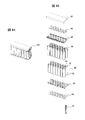
- FIG. 1A is a perspective view of an example of an assembled battery constituting a power supply device.
- FIG. 1B is an exploded perspective view of an example of an assembled battery constituting the power supply device.
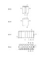
- FIG. 2A is a side view of the assembled battery 100 in FIG. 1A as viewed from the arrow X1 side.
- FIG. 2B is a side view of the assembled battery 100 in FIG. 1A as viewed from the side of the arrow X2.
- FIG. 2C is a side view of the assembled battery 100 in FIG. 1A as viewed from the direction of the arrow Y.
- FIG. 2D is a top view of the assembled battery 100 in FIG. 1A as viewed from the direction of the arrow Z.
- FIG. 1A is a perspective view of an example of an assembled battery constituting a power supply device.
- FIG. 1B is an exploded perspective view of an example of an assembled battery constituting the power supply device.
- FIG. 2A is a side view of the assembled battery 100 in FIG
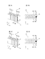
- FIG. 3A is a perspective view showing a position where a bus bar is arranged in a case where a group of unit cells is arranged in the closest packing.
- FIG. 3B is a top view showing a position where the bus bars are arranged when the group of single cells is arranged in the closest packing.
- FIG. 3C is a perspective view showing a position where a bus bar is arranged when a group of unit cells is arranged in a cube.
- FIG. 3D is a top view showing a position where the bus bar is arranged when the group of single cells is arranged in a cube.
- FIG. 4A is a perspective view of an example of an assembled battery constituting a power supply device having an explosion-proof structure.
- FIG. 4A is a perspective view of an example of an assembled battery constituting a power supply device having an explosion-proof structure.
- FIG. 4B is an exploded perspective view of an example of an assembled battery constituting a power supply device having an explosion-proof structure. It is a figure which shows the state which connects two assembled batteries.
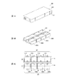
- FIG. 6A is an external perspective view of one embodiment of a power supply device.
- FIG. 6B is an internal perspective view of one embodiment of the power supply device.
- FIG. 6C is an internal top view of one embodiment of the power supply.
- FIG. 7 is an internal top view of a modification of the embodiment of the power supply device.
- the power supply device of the present invention includes two or more assembled batteries, and the assembled batteries are electrically connected to each other.
- the electrical connection between the assembled batteries may be a series connection or a parallel connection.
- the battery pack is electrically connected through a bus bar.
- each unit cell is preferably arranged on the same plane.
- the battery pack includes a plurality of columnar unit cells, an electrode plate disposed on the column top of the unit cell, and an electrode plate disposed on the column bottom of the unit cell.
- the electrode plate arranged at the column top of the unit cell is connected to the electrode terminal at the column top of the unit cell.
- the electrode plate arranged at the column bottom of the unit cell is connected to the electrode terminal at the column bottom of the unit cell.
- the plurality of single cells included in the assembled battery may be supported by a housing member called a housing.
- the housing can be, for example, an assembly of pipe-shaped members that can accommodate each unit cell (see the pipe-shaped member 30 in FIG. 1), a casting that has holes that can accommodate each unit cell, and the like.
- the bus bar may be a conductor member that electrically connects the assembled batteries, and may be a flexible wiring member or a rigid metal bar. However, from the viewpoint of facilitating connection work between the assembled batteries, a rigid metal rod may be used.
- the metal bar may be a solid bar or a hollow bar. Examples of metals include copper, iron, nickel, aluminum, or alloys thereof.
- the bus bar may be a multilayer plywood containing those metals.
- the metal bar constituting the bus bar preferably has an outer diameter of ⁇ 5 to 20 mm. Sufficient strength is obtained by setting the outer diameter ⁇ to 5 mm or more. On the other hand, when the outer diameter ⁇ is 20 mm or less, the assembled batteries can be connected to each other in a space efficient manner. Further, the metal bar constituting the bus bar may be a solid bar or a hollow bar (pipe shape).
- FIG. 1A is a perspective view of an assembled battery 100 constituting a power supply device.
- FIG. 1B is an exploded perspective view of the assembled battery 100 constituting the power supply device.
- the assembled battery 100 includes an electrode plate 10, a holder 20, a housing formed of a plurality of pipe-shaped members 30 (30a, 30b,... 30t), and a plurality of single cells 40 (40a, 40b). ,..., 40t), a holder 50, an electrode plate 60, and a bus bar 70.
- Each cell 40 is accommodated in the pipe-shaped member 30.
- the accommodated unit cell 40 is supported by the holder 20 and the holder 50.
- One electrode 41 of the unit cell is connected to the electrode plate 10, and the other electrode 42 is connected to the electrode plate 60.
- the bus bar 70 is connected to the electrode plate 10, but is not connected to the electrode plate 60.
- the bus bar 70 may be inseparably connected to the electrode plate 10 or may be detachably connected. For example, if the bus bar 70 is metallurgically joined to the electrode plate 10, it is usually inseparable. If the bus bar 70 is fixed to the electrode plate 10 with a screw, it is detachably connected.
- FIG. 2A is a side view of the assembled battery 100 in FIG. 1A as viewed from the arrow X1 side.
- FIG. 2B is a side view of the assembled battery 100 in FIG. 1A as viewed from the side of the arrow X2.
- FIG. 2C is a side view of the assembled battery 100 in FIG. 1A as viewed from the direction of the arrow Y.
- FIG. 2D is a top view of the assembled battery 100 in FIG. 1A as viewed from the direction of the arrow Z.
- a bus bar 70 is disposed at one end in the length direction of the electrode plate 10 (the assembled battery 100). One end of the bus bar 70 is joined to the electrode plate 10. On the other hand, the other end of the bus bar 70 is not joined to the electrode plate 60 but can be joined to another member.
- the bus bar 70 is bonded to the electrode plate 10 by mechanical or metallurgical bonding.
- the cells in the assembled battery are preferably arranged in the same plane.
- the arrangement is not particularly limited, but it is necessary to provide a gap between the arranged cells.
- the cells may be arranged in the closest packing.
- they may be arranged in a cube.
- FIG. 3A is a perspective view showing a state in which a plurality of unit cells 40 (40a, 40b,... 40t) are arranged in the closest packed arrangement.
- FIG. 3B is a top view of the plurality of unit cells 40 corresponding to FIG. 3A.
- the plurality of single cells 40 (40a, 40b,... 40t) are arranged in three rows in a close-packed state.
- the bus bar 70 is disposed along a dotted line 71 between the cells 40g at the right end of the first row and the cells 40t at the right end of the third row.
- the bus bar 70 is arranged at the right end in the length (X) direction and the position 72 in the second row in the width (Y) direction of the plurality of unit cells 40. By arranging the bus bar 70 in this way, a part of the bus bar 70 is arranged in the gap between the single cells 40.
- FIG. 3C is a perspective view showing a state in which a plurality of unit cells 40 (40a, 40b,... 40t) are arranged in a cubic manner.
- FIG. 3D is a top view of the plurality of unit cells 40 corresponding to FIG. 3C.
- the plurality of single cells 40 (40a, 40b,... 40t) are arranged in three rows in a cubic arrangement state.
- the bus bar 70 is arranged along a dotted line 71 between the cells 40g at the right end of the first row and the cells 40t at the right end of the third row. Further, as shown in FIG.
- the bus bar 70 is disposed at the right end in the length (X) direction and the position 72 in the second row in the width (Y) direction of the plurality of unit cells 40.
- the bus bar 70 is arranged in this way, a part of the bus bar 70 is arranged in the gap between the single cells 40.
- the space for arranging the bus bars can be minimized. Therefore, when the power supply device is manufactured by combining the assembled batteries 100A and 100B, the volume of the entire power supply device can be reduced.
- bus bar 70 should just be arrange
- FIG. For example, as shown in the dotted lines in FIG. 3B and FIG. 3D, it is only necessary that a part of the bus bar 70 is disposed inside the straight line (common tangent line) connecting the edges of the unit cells. .
- bus bar 70 is disposed in the gap between the single cells 40, it is preferable that the bus bars 70 are separated without contacting the single cells 40 or the pipe-shaped member 30 covering the single cells 40. This is to prevent heat generation of the assembled battery during power generation by flowing the refrigerant through the separation portion.
- the bus bar 70 may be a pipe-shaped hollow bar. In that case, you may use the hollow part of a hollow bar as an exhaust flow path.
- Each unit cell 40 has a possibility of thermal runaway due to some trouble. For such fear, each cell 40 preferably has a safety valve called an explosion-proof valve 43 (see FIG. 4B).
- the explosion-proof valve 43 prevents the single cell 40 from exploding by releasing the internal pressure when the internal pressure of the single cell 40 increases excessively.
- the gas when the explosion-proof valve 43 is opened can be exhausted to the outside through a flow path composed of the hollow portions of the explosion-proof hood 80 and the bus bar 70.
- FIG. 4A and 4B show an assembled battery 100 'having an explosion-proof structure.
- FIG. 4A is a perspective view of the battery pack 100 ′.
- FIG. 4B is an exploded perspective view of the battery pack 100 ′.
- the assembled battery 100 ′ includes an explosion-proof hood 80, an electrode plate 10, a holder 20, a housing including a plurality of pipe-shaped members 30, a plurality of unit cells 40 ′, and a holder 50.
- the electrode plate 60 and the bus bar 70 are provided.
- the electrode plate 10, the holder 20, a housing made up of a plurality of pipe-shaped members 30, the holder 50, the electrode plate 60, and the bus bar 70 are the same as those shown in FIG. 1A.
- the unit cell 40 ′ of the assembled battery 100 ′ has an explosion-proof valve 43. Further, the explosion-proof hood 80 forms a sealed space above the unit cell 40 '. The sealed space formed by the explosion-proof hood 80 communicates with the hollow portion of the bus bar 70. Therefore, if the explosion-proof valve of the unit cell 40 ′ is opened, the exhaust gas is produced outside the assembled battery 100 ′ through the sealed space formed by the explosion-proof hood 80 and the hollow portion of the bus bar 70.
- FIG. 5 shows a state where two assembled batteries (100A and 100B) are connected via a bus bar.
- the assembled battery 100A includes a plurality of pipe-shaped members 30A that accommodate the unit cells 40A, and further includes an electrode plate 10A and an electrode plate 60A.
- the assembled battery 100B includes a plurality of pipe-shaped members 30B that accommodate the unit cells 40B, and includes an electrode plate 10B and an electrode plate 60B.
- the assembled battery 100A has a bus bar 70A, and one end of the bus bar 70A is connected to the electrode plate 10A, but the other end is not connected to the electrode plate 60A.
- the electrode plate 60B of the assembled battery 100B has a connection part 61B for connecting the other end of the bus bar 70A.
- the assembled battery 100B may also have a bus bar 70B (not shown) connected to the electrode plate 10B, similarly to the assembled battery 100A.
- the bus bar 70B may be connected to the connection portion 61C of the electrode plate 60C of the assembled battery 100C (not shown) to obtain a higher-capacity power supply device.
- FIG. 6A is an external perspective view of one embodiment of a power supply device.
- FIG. 6B is an internal perspective view of one embodiment of the power supply device.
- FIG. 6C is an internal top view of one embodiment of the power supply.
- the power supply device 200 includes a rectangular parallelepiped main body case 201 and a lid body 202 disposed on the upper surface of the main body case. In the body case 201, as shown in FIG.
- At least a part of the bus bar is disposed in a gap between the cells a at one end in the length direction of the assembled battery 100A.
- FIG. 7 is an internal top view of a modification of the embodiment of the power supply device.
- the first and second battery modules 301 and 302 may be arranged so that the anode side of the first battery module 301 and the negative electrode side of the second battery module 302 face each other. Good.
- the anode at one end of the first battery module 301 and the anode at one end of the second battery module 302 are preferably electrically connected via the bus bar 70.
- the arrangement shown in FIG. 6C is preferable. This is because the number of members can be reduced because only one explosion-proof hood is required.
- the power supply device of the present invention is a large-capacity power supply device because it has a plurality of assembled batteries electrically connected to each other. And since the connection part which electrically connects an assembled battery is compact, it is a power supply device with high energy density. Therefore, it can be used for a power supply device for applications where an increase in capacity and an improvement in energy density are desired.
- Electrode plate 20 Holder 30, 30A, 30B Pipe-like member 40 Single cell 40 'Single cell with explosion-proof valve 41 Electrode 42 Electrode 43 Explosion-proof valve 50 Holder 60, 60A, 60B Electrode plate 70, 70A, 70B Bus bar 80 Explosion-proof hood 100, 100A, 100B Battery pack 100 'Battery pack having explosion-proof structure 200 Power supply device 201 Main body case 202 Lid 301 First battery module 302 Second battery module
Landscapes
- Chemical & Material Sciences (AREA)
- Chemical Kinetics & Catalysis (AREA)
- Electrochemistry (AREA)
- General Chemical & Material Sciences (AREA)
- Inorganic Chemistry (AREA)
- Battery Mounting, Suspending (AREA)
- Connection Of Batteries Or Terminals (AREA)
- Gas Exhaust Devices For Batteries (AREA)
- Secondary Cells (AREA)
Abstract
La présente invention concerne un appareil d'alimentation qui comprend une batterie assemblée (A) comportant une pluralité de batteries unitaires (a) disposées sur le même plan, et une batterie assemblée (B) comportant une pluralité de batteries unitaires (b) disposées sur le même plan. Dans l'appareil d'alimentation, les électrodes de la batterie assemblée (A) et les électrodes de la batterie assemblée (B) sont électriquement connectées entre elles par le biais d'une barre omnibus, et au moins une partie de la barre omnibus est disposée dans un espace entre les batteries unitaires (a) de la batterie assemblée (A). Dans cet appareil d'alimentation dans lequel les batteries assemblées sont connectées, la densité énergétique de l'appareil d'alimentation peut être facilement augmentée et les batteries assemblées peuvent être facilement connectées électriquement entre elles, par la réduction de la capacité d'une section connexion électrique des batteries assemblées.
Applications Claiming Priority (2)
| Application Number | Priority Date | Filing Date | Title |
|---|---|---|---|
| JP2011121640 | 2011-05-31 | ||
| JP2011-121640 | 2011-05-31 |
Publications (1)
| Publication Number | Publication Date |
|---|---|
| WO2012164837A1 true WO2012164837A1 (fr) | 2012-12-06 |
Family
ID=47258715
Family Applications (1)
| Application Number | Title | Priority Date | Filing Date |
|---|---|---|---|
| PCT/JP2012/003111 Ceased WO2012164837A1 (fr) | 2011-05-31 | 2012-05-11 | Appareil d'alimentation |
Country Status (2)
| Country | Link |
|---|---|
| JP (1) | JPWO2012164837A1 (fr) |
| WO (1) | WO2012164837A1 (fr) |
Cited By (12)
| Publication number | Priority date | Publication date | Assignee | Title |
|---|---|---|---|---|
| CN103280548A (zh) * | 2013-01-16 | 2013-09-04 | 许祎凡 | 电池连接装置以及应用该电池连接装置的电池组件 |
| WO2014119287A1 (fr) * | 2013-01-29 | 2014-08-07 | 三洋電機株式会社 | Bloc batterie, module de piles et support de bloc batterie |
| WO2014125807A1 (fr) * | 2013-02-14 | 2014-08-21 | 三洋電機株式会社 | Module de batterie |
| WO2015019570A1 (fr) * | 2013-08-08 | 2015-02-12 | パナソニックIpマネジメント株式会社 | Unité de batterie |
| JP2015141765A (ja) * | 2014-01-27 | 2015-08-03 | ダイキョーニシカワ株式会社 | 電池モジュール |
| JPWO2014156022A1 (ja) * | 2013-03-29 | 2017-02-16 | 三洋電機株式会社 | 電池ブロック |
| WO2018003467A1 (fr) * | 2016-06-29 | 2018-01-04 | パナソニックIpマネジメント株式会社 | Bloc-batterie et module de batterie |
| CN108899464A (zh) * | 2018-07-02 | 2018-11-27 | 中兴高能技术有限责任公司 | 一种电池模组的汇流排和电池模组 |
| CN110752341A (zh) * | 2019-09-20 | 2020-02-04 | 杭州乾代科技有限公司 | 适用于模块化锂电池模组的并联端子及其制造方法 |
| JP2020522850A (ja) * | 2017-12-26 | 2020-07-30 | エルジー・ケム・リミテッド | 空間活用性及び安全性が向上した円筒型電池セル組立体、及びそれを含むバッテリーモジュール |
| JP2025114223A (ja) * | 2024-01-24 | 2025-08-05 | 本田技研工業株式会社 | 電池パック及び電池パックの製造方法 |
| JP2025114221A (ja) * | 2024-01-24 | 2025-08-05 | 本田技研工業株式会社 | 電池パック |
Families Citing this family (1)
| Publication number | Priority date | Publication date | Assignee | Title |
|---|---|---|---|---|
| KR102727483B1 (ko) | 2019-10-10 | 2024-11-06 | 주식회사 엘지에너지솔루션 | 쇼트 방지 및 충격 보호 구조가 강화된 배터리 팩 |
Citations (6)
| Publication number | Priority date | Publication date | Assignee | Title |
|---|---|---|---|---|
| JPS51114636A (en) * | 1975-03-17 | 1976-10-08 | Comp Generale Electricite | Battery |
| JPS57119458A (en) * | 1981-01-17 | 1982-07-24 | Sanyo Electric Co Ltd | Storage battery |
| JPS62200250U (fr) * | 1986-06-10 | 1987-12-19 | ||
| JPH02500396A (ja) * | 1987-07-03 | 1990-02-08 | クローライド サイレント パワー リミテッド | バッテリー |
| JP2000067833A (ja) * | 1998-08-25 | 2000-03-03 | Nissan Motor Co Ltd | 電気自動車のバッテリ接続構造および接続方法 |
| JP2009164085A (ja) * | 2008-01-10 | 2009-07-23 | Hitachi Vehicle Energy Ltd | 電池モジュール |
-
2012
- 2012-05-11 JP JP2012534888A patent/JPWO2012164837A1/ja active Pending
- 2012-05-11 WO PCT/JP2012/003111 patent/WO2012164837A1/fr not_active Ceased
Patent Citations (6)
| Publication number | Priority date | Publication date | Assignee | Title |
|---|---|---|---|---|
| JPS51114636A (en) * | 1975-03-17 | 1976-10-08 | Comp Generale Electricite | Battery |
| JPS57119458A (en) * | 1981-01-17 | 1982-07-24 | Sanyo Electric Co Ltd | Storage battery |
| JPS62200250U (fr) * | 1986-06-10 | 1987-12-19 | ||
| JPH02500396A (ja) * | 1987-07-03 | 1990-02-08 | クローライド サイレント パワー リミテッド | バッテリー |
| JP2000067833A (ja) * | 1998-08-25 | 2000-03-03 | Nissan Motor Co Ltd | 電気自動車のバッテリ接続構造および接続方法 |
| JP2009164085A (ja) * | 2008-01-10 | 2009-07-23 | Hitachi Vehicle Energy Ltd | 電池モジュール |
Cited By (24)
| Publication number | Priority date | Publication date | Assignee | Title |
|---|---|---|---|---|
| CN103280548A (zh) * | 2013-01-16 | 2013-09-04 | 许祎凡 | 电池连接装置以及应用该电池连接装置的电池组件 |
| WO2014119287A1 (fr) * | 2013-01-29 | 2014-08-07 | 三洋電機株式会社 | Bloc batterie, module de piles et support de bloc batterie |
| US20150325824A1 (en) * | 2013-01-29 | 2015-11-12 | Sanyo Electric Co., Ltd. | Battery block, battery module, and battery block holder |
| JPWO2014119287A1 (ja) * | 2013-01-29 | 2017-01-26 | 三洋電機株式会社 | 電池ブロック、電池モジュール及び電池ブロック用ホルダ |
| WO2014125807A1 (fr) * | 2013-02-14 | 2014-08-21 | 三洋電機株式会社 | Module de batterie |
| JPWO2014125807A1 (ja) * | 2013-02-14 | 2017-02-02 | 三洋電機株式会社 | 電池モジュール |
| JP2017224627A (ja) * | 2013-02-14 | 2017-12-21 | 三洋電機株式会社 | 電池モジュール |
| JPWO2014156022A1 (ja) * | 2013-03-29 | 2017-02-16 | 三洋電機株式会社 | 電池ブロック |
| WO2015019570A1 (fr) * | 2013-08-08 | 2015-02-12 | パナソニックIpマネジメント株式会社 | Unité de batterie |
| JP2015141765A (ja) * | 2014-01-27 | 2015-08-03 | ダイキョーニシカワ株式会社 | 電池モジュール |
| CN109328407A (zh) * | 2016-06-29 | 2019-02-12 | 松下知识产权经营株式会社 | 电池块以及电池模块 |
| US10910611B2 (en) | 2016-06-29 | 2021-02-02 | Panasonic Intellectual Property Management Co., Ltd. | Battery block and battery module |
| WO2018003467A1 (fr) * | 2016-06-29 | 2018-01-04 | パナソニックIpマネジメント株式会社 | Bloc-batterie et module de batterie |
| JPWO2018003467A1 (ja) * | 2016-06-29 | 2019-04-25 | パナソニックIpマネジメント株式会社 | 電池ブロック及び電池モジュール |
| US20190305262A1 (en) * | 2016-06-29 | 2019-10-03 | Panasonic Intellectual Property Management Co., Ltd. | Battery block and battery module |
| CN109328407B (zh) * | 2016-06-29 | 2022-01-04 | 松下知识产权经营株式会社 | 电池块以及电池模块 |
| JP2020522850A (ja) * | 2017-12-26 | 2020-07-30 | エルジー・ケム・リミテッド | 空間活用性及び安全性が向上した円筒型電池セル組立体、及びそれを含むバッテリーモジュール |
| JP7045597B2 (ja) | 2017-12-26 | 2022-04-01 | エルジー エナジー ソリューション リミテッド | 空間活用性及び安全性が向上した円筒型電池セル組立体、及びそれを含むバッテリーモジュール |
| CN108899464A (zh) * | 2018-07-02 | 2018-11-27 | 中兴高能技术有限责任公司 | 一种电池模组的汇流排和电池模组 |
| CN110752341A (zh) * | 2019-09-20 | 2020-02-04 | 杭州乾代科技有限公司 | 适用于模块化锂电池模组的并联端子及其制造方法 |
| JP2025114223A (ja) * | 2024-01-24 | 2025-08-05 | 本田技研工業株式会社 | 電池パック及び電池パックの製造方法 |
| JP2025114221A (ja) * | 2024-01-24 | 2025-08-05 | 本田技研工業株式会社 | 電池パック |
| JP7798927B2 (ja) | 2024-01-24 | 2026-01-14 | 本田技研工業株式会社 | 電池パック |
| JP7798928B2 (ja) | 2024-01-24 | 2026-01-14 | 本田技研工業株式会社 | 電池パック及び電池パックの製造方法 |
Also Published As
| Publication number | Publication date |
|---|---|
| JPWO2012164837A1 (ja) | 2015-02-23 |
Similar Documents
| Publication | Publication Date | Title |
|---|---|---|
| WO2012164837A1 (fr) | Appareil d'alimentation | |
| JP5824612B2 (ja) | 電池モジュール | |
| KR101053208B1 (ko) | 용접 신뢰성이 향상된 전지모듈 및 이를 포함하는 중대형 전지팩 | |
| TWI453978B (zh) | 高輸出,大容量電池組 | |
| JP5490516B2 (ja) | 電池パック | |
| EP4369497A2 (fr) | Bloc-batterie et véhicule électrique | |
| JP5160425B2 (ja) | 電池モジュールの製作に適した電池 | |
| JP5105390B2 (ja) | 大電流放電用薄形二次電池及び電池モジュール | |
| CN101395740A (zh) | 中型或大型电池模块 | |
| JP7189227B2 (ja) | 電池モジュール及び電池パック | |
| WO2012073399A1 (fr) | Module de batterie et bloc-batterie | |
| WO2019244402A1 (fr) | Module de batterie secondaire | |
| CN102473871A (zh) | 电池组 | |
| CN108140779A (zh) | 电池模组以及包含该电池模组的电池包和车辆 | |
| EP2704229A1 (fr) | Batterie secondaire | |
| CN221176394U (zh) | 电池、用电装置及储能装置 | |
| US11563254B2 (en) | Battery module and battery pack | |
| JP4894198B2 (ja) | 組電池 | |
| JP4955398B2 (ja) | 電気デバイス集合体 | |
| CN116895918A (zh) | 电池组 | |
| JP7532788B2 (ja) | 電池モジュール | |
| JP2008270350A (ja) | 積層型電力貯蔵デバイス | |
| JP2008159328A (ja) | 電池モジュール | |
| KR20230153902A (ko) | 배터리 모듈 구조와 이를 적용한 배터리 모듈 및 이를 포함하는 배터리 팩 | |
| JP7783574B2 (ja) | 組電池 |
Legal Events
| Date | Code | Title | Description |
|---|---|---|---|
| ENP | Entry into the national phase |
Ref document number: 2012534888 Country of ref document: JP Kind code of ref document: A |
|
| 121 | Ep: the epo has been informed by wipo that ep was designated in this application |
Ref document number: 12794156 Country of ref document: EP Kind code of ref document: A1 |
|
| NENP | Non-entry into the national phase |
Ref country code: DE |
|
| 122 | Ep: pct application non-entry in european phase |
Ref document number: 12794156 Country of ref document: EP Kind code of ref document: A1 |