WO2012164907A1 - 多電源式鉄道車両用の空調電源システム - Google Patents
多電源式鉄道車両用の空調電源システム Download PDFInfo
- Publication number
- WO2012164907A1 WO2012164907A1 PCT/JP2012/003494 JP2012003494W WO2012164907A1 WO 2012164907 A1 WO2012164907 A1 WO 2012164907A1 JP 2012003494 W JP2012003494 W JP 2012003494W WO 2012164907 A1 WO2012164907 A1 WO 2012164907A1
- Authority
- WO
- WIPO (PCT)
- Prior art keywords
- voltage
- power supply
- auxiliary power
- air conditioner
- air
- Prior art date
- Legal status (The legal status is an assumption and is not a legal conclusion. Google has not performed a legal analysis and makes no representation as to the accuracy of the status listed.)
- Ceased
Links
Images

Classifications
-
- B—PERFORMING OPERATIONS; TRANSPORTING
- B60—VEHICLES IN GENERAL
- B60L—PROPULSION OF ELECTRICALLY-PROPELLED VEHICLES; SUPPLYING ELECTRIC POWER FOR AUXILIARY EQUIPMENT OF ELECTRICALLY-PROPELLED VEHICLES; ELECTRODYNAMIC BRAKE SYSTEMS FOR VEHICLES IN GENERAL; MAGNETIC SUSPENSION OR LEVITATION FOR VEHICLES; MONITORING OPERATING VARIABLES OF ELECTRICALLY-PROPELLED VEHICLES; ELECTRIC SAFETY DEVICES FOR ELECTRICALLY-PROPELLED VEHICLES
- B60L1/00—Supplying electric power to auxiliary equipment of vehicles
- B60L1/003—Supplying electric power to auxiliary equipment of vehicles to auxiliary motors, e.g. for pumps, compressors
-
- B—PERFORMING OPERATIONS; TRANSPORTING
- B60—VEHICLES IN GENERAL
- B60L—PROPULSION OF ELECTRICALLY-PROPELLED VEHICLES; SUPPLYING ELECTRIC POWER FOR AUXILIARY EQUIPMENT OF ELECTRICALLY-PROPELLED VEHICLES; ELECTRODYNAMIC BRAKE SYSTEMS FOR VEHICLES IN GENERAL; MAGNETIC SUSPENSION OR LEVITATION FOR VEHICLES; MONITORING OPERATING VARIABLES OF ELECTRICALLY-PROPELLED VEHICLES; ELECTRIC SAFETY DEVICES FOR ELECTRICALLY-PROPELLED VEHICLES
- B60L1/00—Supplying electric power to auxiliary equipment of vehicles
- B60L1/02—Supplying electric power to auxiliary equipment of vehicles to electric heating circuits
- B60L1/04—Supplying electric power to auxiliary equipment of vehicles to electric heating circuits fed by the power supply line
- B60L1/06—Supplying electric power to auxiliary equipment of vehicles to electric heating circuits fed by the power supply line using only one supply
-
- B—PERFORMING OPERATIONS; TRANSPORTING
- B60—VEHICLES IN GENERAL
- B60L—PROPULSION OF ELECTRICALLY-PROPELLED VEHICLES; SUPPLYING ELECTRIC POWER FOR AUXILIARY EQUIPMENT OF ELECTRICALLY-PROPELLED VEHICLES; ELECTRODYNAMIC BRAKE SYSTEMS FOR VEHICLES IN GENERAL; MAGNETIC SUSPENSION OR LEVITATION FOR VEHICLES; MONITORING OPERATING VARIABLES OF ELECTRICALLY-PROPELLED VEHICLES; ELECTRIC SAFETY DEVICES FOR ELECTRICALLY-PROPELLED VEHICLES
- B60L15/00—Methods, circuits, or devices for controlling the traction-motor speed of electrically-propelled vehicles
- B60L15/20—Methods, circuits, or devices for controlling the traction-motor speed of electrically-propelled vehicles for control of the vehicle or its driving motor to achieve a desired performance, e.g. speed, torque, programmed variation of speed
-
- B—PERFORMING OPERATIONS; TRANSPORTING
- B60—VEHICLES IN GENERAL
- B60L—PROPULSION OF ELECTRICALLY-PROPELLED VEHICLES; SUPPLYING ELECTRIC POWER FOR AUXILIARY EQUIPMENT OF ELECTRICALLY-PROPELLED VEHICLES; ELECTRODYNAMIC BRAKE SYSTEMS FOR VEHICLES IN GENERAL; MAGNETIC SUSPENSION OR LEVITATION FOR VEHICLES; MONITORING OPERATING VARIABLES OF ELECTRICALLY-PROPELLED VEHICLES; ELECTRIC SAFETY DEVICES FOR ELECTRICALLY-PROPELLED VEHICLES
- B60L9/00—Electric propulsion with power supply external to the vehicle
- B60L9/02—Electric propulsion with power supply external to the vehicle using DC motors
- B60L9/08—Electric propulsion with power supply external to the vehicle using DC motors fed from AC supply lines
- B60L9/12—Electric propulsion with power supply external to the vehicle using DC motors fed from AC supply lines with static converters
-
- B—PERFORMING OPERATIONS; TRANSPORTING
- B60—VEHICLES IN GENERAL
- B60L—PROPULSION OF ELECTRICALLY-PROPELLED VEHICLES; SUPPLYING ELECTRIC POWER FOR AUXILIARY EQUIPMENT OF ELECTRICALLY-PROPELLED VEHICLES; ELECTRODYNAMIC BRAKE SYSTEMS FOR VEHICLES IN GENERAL; MAGNETIC SUSPENSION OR LEVITATION FOR VEHICLES; MONITORING OPERATING VARIABLES OF ELECTRICALLY-PROPELLED VEHICLES; ELECTRIC SAFETY DEVICES FOR ELECTRICALLY-PROPELLED VEHICLES
- B60L9/00—Electric propulsion with power supply external to the vehicle
- B60L9/16—Electric propulsion with power supply external to the vehicle using AC induction motors
- B60L9/18—Electric propulsion with power supply external to the vehicle using AC induction motors fed from DC supply lines
-
- B—PERFORMING OPERATIONS; TRANSPORTING
- B60—VEHICLES IN GENERAL
- B60L—PROPULSION OF ELECTRICALLY-PROPELLED VEHICLES; SUPPLYING ELECTRIC POWER FOR AUXILIARY EQUIPMENT OF ELECTRICALLY-PROPELLED VEHICLES; ELECTRODYNAMIC BRAKE SYSTEMS FOR VEHICLES IN GENERAL; MAGNETIC SUSPENSION OR LEVITATION FOR VEHICLES; MONITORING OPERATING VARIABLES OF ELECTRICALLY-PROPELLED VEHICLES; ELECTRIC SAFETY DEVICES FOR ELECTRICALLY-PROPELLED VEHICLES
- B60L2200/00—Type of vehicles
- B60L2200/26—Rail vehicles
-
- B—PERFORMING OPERATIONS; TRANSPORTING
- B60—VEHICLES IN GENERAL
- B60L—PROPULSION OF ELECTRICALLY-PROPELLED VEHICLES; SUPPLYING ELECTRIC POWER FOR AUXILIARY EQUIPMENT OF ELECTRICALLY-PROPELLED VEHICLES; ELECTRODYNAMIC BRAKE SYSTEMS FOR VEHICLES IN GENERAL; MAGNETIC SUSPENSION OR LEVITATION FOR VEHICLES; MONITORING OPERATING VARIABLES OF ELECTRICALLY-PROPELLED VEHICLES; ELECTRIC SAFETY DEVICES FOR ELECTRICALLY-PROPELLED VEHICLES
- B60L2210/00—Converter types
- B60L2210/10—DC to DC converters
- B60L2210/12—Buck converters
-
- B—PERFORMING OPERATIONS; TRANSPORTING
- B60—VEHICLES IN GENERAL
- B60L—PROPULSION OF ELECTRICALLY-PROPELLED VEHICLES; SUPPLYING ELECTRIC POWER FOR AUXILIARY EQUIPMENT OF ELECTRICALLY-PROPELLED VEHICLES; ELECTRODYNAMIC BRAKE SYSTEMS FOR VEHICLES IN GENERAL; MAGNETIC SUSPENSION OR LEVITATION FOR VEHICLES; MONITORING OPERATING VARIABLES OF ELECTRICALLY-PROPELLED VEHICLES; ELECTRIC SAFETY DEVICES FOR ELECTRICALLY-PROPELLED VEHICLES
- B60L2210/00—Converter types
- B60L2210/30—AC to DC converters
-
- B—PERFORMING OPERATIONS; TRANSPORTING
- B60—VEHICLES IN GENERAL
- B60L—PROPULSION OF ELECTRICALLY-PROPELLED VEHICLES; SUPPLYING ELECTRIC POWER FOR AUXILIARY EQUIPMENT OF ELECTRICALLY-PROPELLED VEHICLES; ELECTRODYNAMIC BRAKE SYSTEMS FOR VEHICLES IN GENERAL; MAGNETIC SUSPENSION OR LEVITATION FOR VEHICLES; MONITORING OPERATING VARIABLES OF ELECTRICALLY-PROPELLED VEHICLES; ELECTRIC SAFETY DEVICES FOR ELECTRICALLY-PROPELLED VEHICLES
- B60L2210/00—Converter types
- B60L2210/40—DC to AC converters
-
- B—PERFORMING OPERATIONS; TRANSPORTING
- B60—VEHICLES IN GENERAL
- B60L—PROPULSION OF ELECTRICALLY-PROPELLED VEHICLES; SUPPLYING ELECTRIC POWER FOR AUXILIARY EQUIPMENT OF ELECTRICALLY-PROPELLED VEHICLES; ELECTRODYNAMIC BRAKE SYSTEMS FOR VEHICLES IN GENERAL; MAGNETIC SUSPENSION OR LEVITATION FOR VEHICLES; MONITORING OPERATING VARIABLES OF ELECTRICALLY-PROPELLED VEHICLES; ELECTRIC SAFETY DEVICES FOR ELECTRICALLY-PROPELLED VEHICLES
- B60L2240/00—Control parameters of input or output; Target parameters
- B60L2240/10—Vehicle control parameters
- B60L2240/34—Cabin temperature
-
- B—PERFORMING OPERATIONS; TRANSPORTING
- B60—VEHICLES IN GENERAL
- B60L—PROPULSION OF ELECTRICALLY-PROPELLED VEHICLES; SUPPLYING ELECTRIC POWER FOR AUXILIARY EQUIPMENT OF ELECTRICALLY-PROPELLED VEHICLES; ELECTRODYNAMIC BRAKE SYSTEMS FOR VEHICLES IN GENERAL; MAGNETIC SUSPENSION OR LEVITATION FOR VEHICLES; MONITORING OPERATING VARIABLES OF ELECTRICALLY-PROPELLED VEHICLES; ELECTRIC SAFETY DEVICES FOR ELECTRICALLY-PROPELLED VEHICLES
- B60L2240/00—Control parameters of input or output; Target parameters
- B60L2240/40—Drive Train control parameters
- B60L2240/42—Drive Train control parameters related to electric machines
- B60L2240/421—Speed
-
- B—PERFORMING OPERATIONS; TRANSPORTING
- B60—VEHICLES IN GENERAL
- B60L—PROPULSION OF ELECTRICALLY-PROPELLED VEHICLES; SUPPLYING ELECTRIC POWER FOR AUXILIARY EQUIPMENT OF ELECTRICALLY-PROPELLED VEHICLES; ELECTRODYNAMIC BRAKE SYSTEMS FOR VEHICLES IN GENERAL; MAGNETIC SUSPENSION OR LEVITATION FOR VEHICLES; MONITORING OPERATING VARIABLES OF ELECTRICALLY-PROPELLED VEHICLES; ELECTRIC SAFETY DEVICES FOR ELECTRICALLY-PROPELLED VEHICLES
- B60L2270/00—Problem solutions or means not otherwise provided for
- B60L2270/46—Heat pumps, e.g. for cabin heating
-
- Y—GENERAL TAGGING OF NEW TECHNOLOGICAL DEVELOPMENTS; GENERAL TAGGING OF CROSS-SECTIONAL TECHNOLOGIES SPANNING OVER SEVERAL SECTIONS OF THE IPC; TECHNICAL SUBJECTS COVERED BY FORMER USPC CROSS-REFERENCE ART COLLECTIONS [XRACs] AND DIGESTS
- Y02—TECHNOLOGIES OR APPLICATIONS FOR MITIGATION OR ADAPTATION AGAINST CLIMATE CHANGE
- Y02T—CLIMATE CHANGE MITIGATION TECHNOLOGIES RELATED TO TRANSPORTATION
- Y02T10/00—Road transport of goods or passengers
- Y02T10/60—Other road transportation technologies with climate change mitigation effect
- Y02T10/72—Electric energy management in electromobility
Definitions
- the present invention relates to an air conditioner power supply system for an air conditioner mounted on a multi-power supply type railway vehicle.
- an auxiliary power supply system for railway vehicles has supplied 400V class three-phase AC voltage as power supply to the air conditioner.
- non-insulated power supplies are supplied by omitting the output isolation transformer.
- the peak value of the power supply waveform supplied from the auxiliary power supply is a rectangular wave of 600V class. Since the air conditioner is installed in a place away from the auxiliary power supply, the power supply cable supplied from the auxiliary power supply to the air conditioner is 40 m or longer in the long one, and is supplied to the air conditioner. It has been found that the peak value of the power supply waveform may be more than twice the 600V class (peak value).
- An object of the present invention is to provide an air conditioner system for a multi-power-source railway vehicle that can provide an air conditioner that can cope with this, and can reduce the weight and space of an auxiliary power supply device.
- the air-conditioning power supply system for a multi-power rail vehicle converts a voltage from an overhead line across different sections of the power source into a low-voltage DC voltage when the voltage is lowered by a transformer, and the voltage from the overhead line is Auxiliary power supply device that directly takes in DC and converts it to a DC voltage having the same low voltage as the DC voltage, and an inverter device that converts the DC voltage from the auxiliary power supply device to AC voltage and supplies it to the drive unit of the refrigeration cycle apparatus It is equipped with an air conditioner.
- the auxiliary power supply device converts the voltage from the overhead line across different sections of the power source into a low-voltage DC voltage when the voltage is lowered by the transformer, and directly takes in when the voltage from the overhead line is DC.
- the inverter device of the air conditioner converts the DC voltage into an AC voltage and supplies it to the drive unit of the refrigeration cycle apparatus. This eliminates the need for an inverter device in the auxiliary power supply device, which can contribute to weight reduction and space saving of the auxiliary power supply device.
- the DC voltage output from the auxiliary power supply is one system, it is possible to reduce the weight of the railway vehicle by reducing the armored wire as compared with the conventional multiple systems.
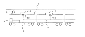
- FIG. 1 It is a block diagram which shows the air-conditioning power supply system for multi-power-supply type rail vehicles which concerns on Embodiment 1.
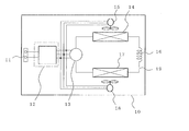
- FIG. 2 It is a schematic block block diagram of the air conditioner shown in FIG.
- FIG. 2 It is a block diagram which shows the air-conditioning power supply system for multiple power supply type rail vehicles which concerns on Embodiment 2.
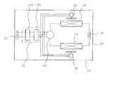
- FIG. 2 It is a schematic block block diagram of the air conditioner shown in FIG.
- FIG. 1 is a block diagram showing an air-conditioning power supply system for a multi-power-supply railway vehicle according to the first embodiment.
- the overhead line 3 that supplies power to the railway vehicle 1 via the pantograph 2 has four power sources that straddle sections of, for example, DC 1500 V, DC 3000 V, AC 15000 V, and AC 25000 V.
- the air conditioning power supply system of the railway vehicle 1 directly takes the DC voltage when the railway vehicle 1 is running with DC 1500V and DC 3000V as the power source and converts it into a low-voltage DC voltage (for example, DC 600V class DC voltage).
- a low-voltage DC voltage for example, DC 600V class DC voltage
- the AC voltage stepped down by the transformer 4 for example, single-phase 800V class AC voltage
- Auxiliary power supply device 5 that converts the direct current voltage into a plurality of air conditioners 10 that are mounted on, for example, each roof of the railway vehicle 1 and are connected to the auxiliary power supply device 5 through a single line of outfitting 6. .
- the auxiliary power supply 5 is a DC / DC converter that converts a DC 1500V or DC 3000V DC voltage into a low voltage DC 600V DC voltage. AC / DC converter etc. to convert to the class.
- the DC 600V class DC voltage converted by the auxiliary power supply device 5 is supplied to the air conditioner 10 through the outfitting line 6 installed in the railway vehicle 1.
- the outfitting wire 6 is a wiring for each air conditioner 10.
- FIG. 2 is a schematic block diagram of the air conditioner shown in FIG.
- the air conditioner 10 includes a two-input terminal 11 to which the rigging wire 6 is connected, an inverter device 12, a refrigeration cycle device, and the like.
- the refrigeration cycle apparatus includes, for example, a compressor 13, a condensing heat exchanger 14 having a blower 15, a pressure reducing device 16 having a capillary tube, an evaporating heat exchanger 17 having a blower 18, and the like sequentially connected by a refrigerant pipe 19.
- a refrigeration cycle apparatus that can be switched between a cooling operation and a heating operation by providing a four-way valve on the discharge side of the compressor 13 may be used.
- the inverter device 12 converts a DC 600V class DC voltage into a predetermined three-phase AC voltage and supplies it to the motors of the compressor 13 and the blowers 15 and 18 which are driving units of the refrigeration cycle apparatus.
- the auxiliary power supply device 5 directly takes in the DC voltage, and the DC / DC converter Is converted to a low pressure DC 600 V class and supplied to the plurality of air conditioners 10 via the rigging wire 6. Further, when the railway vehicle 1 is traveling in the AC section of AC15000V and AC25000V from the DC section, the transformer 4 steps down the AC voltage to a single-phase 800V class AC voltage and supplies it to the auxiliary power supply device 5.
- the auxiliary power supply device 5 converts the single-phase 800 V class AC voltage into a DC 600 V class DC voltage by the AC / DC converter, and supplies the DC voltage to the plurality of air conditioners 10 via the equipment line 6.
- a DC voltage is passed through the equipping line 6, an abnormal peak voltage is not generated in the power supply voltage within the equipping line 6.
- the inverter device 12 of each air conditioner 10 converts the DC 600V class DC voltage input via the two input terminals 11 into a predetermined AC voltage, and the compressor 13 and the blowers 15 and 18 of the refrigeration cycle apparatus. Supply to each motor.
- AC15000V and AC25000V were set as the AC section, there may be an AC section with a low frequency of AC12500V / 25Hz.
- the transformer 4 steps down to a single-phase 800V class AC voltage, and the auxiliary power supply 5 converts the single-phase 800V class AC voltage into a DC 600V class DC voltage. It supplies to the some air conditioner 10 via the rigging wire 6.
- a DC 600V DC voltage is supplied from the auxiliary power supply 5 to the air conditioner 10.
- the three-phase alternating current is supplied by the inverter device 12. Therefore, it is possible to suppress abnormal amplification of the peak value of the voltage generated by the three-phase power source, and it is possible to supply a power source that is easy to insulate the electric motor for the air conditioner 10.
- the inverter device in the auxiliary power supply 5 becomes unnecessary, which can contribute to reduction in size and weight.
- the outfitting line 6 is shared by one system, it can contribute to weight reduction of the railway vehicle 1.
- the air conditioner 10 is provided with an inverter device 12 corresponding to a DC voltage of DC 600 V class, the rotation speed of the motors of the compressors 13 and the blowers 15 and 18 of the heat exchangers 14 and 17 in the air conditioner 10. It is possible to perform energy-saving operation and fine temperature control, thereby contributing to improvement of comfort in the railway vehicle 1.
- the air conditioner 10 can be made smaller and lighter because the air conditioning capacity can be increased by raising the frequency of the motor to 60 Hz or higher, regardless of the power supply status of the overhead line 3, including when the overhead line 3 is AC 12500 V / 25 Hz and the frequency is low. Can contribute.
- FIG. FIG. 3 is a block diagram showing an air-conditioning power supply system for a multi-power-supply railway vehicle according to the second embodiment.
- the overhead line 3 that supplies power to the railway vehicle 1 through the pantograph 2 is four power sources that straddle each section of DC 1500 V, DC 3000 V, AC 15000 V, and AC 25000 V, as in the first embodiment.
- the air conditioning power supply system of the railway vehicle 1 directly takes the DC voltage when the railway vehicle 1 is running with DC 1500V and DC 3000V as the power source and converts it into a low-voltage DC voltage (for example, DC 600V class DC voltage). Further, when the railway vehicle 1 is running with AC 15000V and AC 25000V AC voltages as the power source, when an AC voltage stepped down by the transformer 4 (for example, a single-phase 400V class AC voltage) is input, the AC An auxiliary power supply device 5 that outputs a voltage and a plurality of air conditioners 10 that are mounted on, for example, each roof of the railway vehicle 1 and are connected to the auxiliary power supply device 5 via the lining wire 6 are provided.
- the auxiliary power supply device 5 includes a DC / DC converter that converts a DC voltage of DC 1500 V and DC 3000 V into a low voltage DC 600 V DC voltage.
- the auxiliary power supply device 5 outputs the AC voltage to the air conditioner 10.
- the DC 600V class DC voltage converted by the auxiliary power supply 5 or the single-phase 400V class AC voltage is supplied to the air conditioner 10 via the outfitting line 6 installed in the railway vehicle 1.
- the outfitting wire 6 is a wiring for each air conditioner 10.
- FIG. 4 is a schematic block diagram of the air conditioner shown in FIG.
- the air conditioner 10 includes a three-input terminal 11 to which the rigging wire 6 is connected, an inverter device 12, a refrigeration cycle device, and the like.
- the refrigeration cycle apparatus includes a compressor 13, a condensing heat exchanger 14 having a blower 15, a decompression device 16 having a capillary tube, an evaporating heat exchanger 17 having a blower 18, and the like through a refrigerant pipe 19. Sequentially connected. Note that a refrigeration cycle apparatus that can be switched between a cooling operation and a heating operation by providing a four-way valve on the discharge side of the compressor 13 may be used.
- the aforementioned inverter device 12 includes a rectifying unit 12a and a frequency variable unit 12b.
- the rectifying unit 12a includes, for example, a three-phase full-wave rectifier circuit and a circuit that converts an output from the three-phase full-wave rectifier circuit into a predetermined DC voltage.
- the rectifying unit 12a converts, for example, when a DC voltage is input between the terminals at both ends of the three input terminals 11, and converts the DC voltage to a predetermined DC voltage, and when a single-phase 400V class AC voltage is input to the same terminal, Wave rectification converts the voltage into a predetermined DC voltage.
- the three-phase AC voltage When a three-phase AC voltage is input to the three input terminals 11, full-wave rectification is performed to convert the voltage into a predetermined DC voltage.
- the three-phase AC voltage may be supplied from an external power source other than the auxiliary power device 5.
- the external power source is a power source for performing an operation test in a factory before the air conditioner 10 is mounted on the railway vehicle 1, for example.
- the auxiliary power supply device 5 directly takes in the DC voltage, and the DC / DC converter Is converted to a low pressure DC 600 V class and supplied to the plurality of air conditioners 10 via the rigging wire 6. Further, when the railway vehicle 1 is traveling in the AC section of AC15000V and AC25000V from the DC section, the transformer 4 steps down the AC voltage to a single-phase 400V class AC voltage and supplies it to the auxiliary power supply device 5. At this time, the auxiliary power supply device 5 supplies a single-phase 400 V class AC voltage to the plurality of air conditioners 10 as it is through the equipping line 6. In this case, since a DC voltage and an AC voltage are passed through the equipping line 6 and not a rectangular wave power supply voltage, an abnormal peak voltage is not generated in the power supply voltage within the equipping line 6.
- the rectifying unit 12a of each air conditioner 10 further rectifies when a DC voltage is input between the terminals at both ends of the three input terminals 11, and converts the output into a predetermined DC voltage to convert the frequency into a frequency variable unit.
- To 12b When a single-phase 400V class AC voltage is input to the same terminal, full-wave rectification is performed, and the voltage is converted to a predetermined DC voltage and output to the frequency variable unit 12b.
- the frequency variable unit 12b converts the DC voltage from the rectifying unit 12a into a three-phase AC voltage and supplies it to the compressor 13 and the blowers 15 and 18 that are driving units of the refrigeration cycle apparatus.
- the AC section may be a section with a low frequency of AC12500 V / 25 Hz, as in the first embodiment.
- the transformer 4 steps down to a single-phase 400V class AC voltage, and the auxiliary power supply 5 supplies the single-phase 400V class AC voltage to the Supply to the air conditioner 10.
- the auxiliary power supply device 5 when the railway vehicle 1 is traveling in the DC section, the auxiliary power supply device 5 outputs DC 600V class DC voltage and the railway vehicle 1 travels in the AC section. In this case, a single-phase 400 V class AC voltage stepped down by the transformer 4 is output as it is. This eliminates the need for the inverter device in the auxiliary power supply 5 and eliminates the need for an AC / DC converter that turns the single-phase power supply into a direct current, thereby making the auxiliary power supply 5 smaller and lighter.
- the rectifying unit 12a of the inverter device 12 built in the air conditioner 10 can be applied to a DC power supply, a single-phase AC power supply, and a 3-phase AC power supply, only one three-input terminal 11 is required.
- the outfitting line 6 can be shared by one system, and it can contribute to the weight reduction of the rail vehicle 1.
- the three-phase full-wave rectifier circuit is provided in the rectification unit 12a, it is possible to connect an AC voltage of, for example, three-phase 400V at the factory, and there is an advantage that it is not necessary to prepare a power source for maintenance.
- the inverter device 12 is built in the air conditioner 10, the rotational speed of the compressor 13 in the air conditioner 10 and the motors 15 and 18 in the heat exchangers 14 and 17 are controlled to save energy. Fine temperature control can be performed, which can contribute to improvement of comfort in the railway vehicle 1.
- the air conditioner 10 can be made smaller and lighter because the air conditioning capacity can be increased by raising the frequency of the motor to 60 Hz or higher, regardless of the power supply status of the overhead line 3, including when the overhead line 3 is AC 12500 V / 25 Hz and the frequency is low. Can contribute.
- the air conditioner 10 is provided with the three input terminals 11, and the rectifier 12a is provided with a three-phase full-wave rectifier circuit so that the three-phase AC voltage from the external power source can be rectified.
- a single-phase full-wave rectifier circuit may be used instead of the three-phase full-wave rectifier circuit. In that case, although it becomes impossible to input the three-phase AC voltage from the external power supply, as described above, the auxiliary power supply device 5 can be reduced in size and weight, and the rail vehicle 1 can be reduced in weight by one system of the rigging wire 6.
Landscapes
- Engineering & Computer Science (AREA)
- Power Engineering (AREA)
- Transportation (AREA)
- Mechanical Engineering (AREA)
- Life Sciences & Earth Sciences (AREA)
- Sustainable Development (AREA)
- Sustainable Energy (AREA)
- Electric Propulsion And Braking For Vehicles (AREA)
- Inverter Devices (AREA)
- Rectifiers (AREA)
Abstract
電源の異なる区間を跨がる架線3からの電圧がトランス4により降圧されたときに低圧の直流電圧に変換し、架線3からの電圧が直流のときには直接取り込んで前記直流電圧と同じ低圧の直流電圧に変換する補助電源装置5と、補助電源装置5からの直流電圧を交流電圧に変換し、冷凍サイクル装置の駆動部に供給するインバーター装置を有する空気調和機10とを備えた。
Description
本発明は、多電源式の鉄道車両に搭載される空気調和機の空調電源システムに関するものである。
従来、架線の多電源化に対応するために、鉄道車両用の補助電源システムで空気調和機への電源として400V級の三相交流電圧を供給していたが、その際、補助電源側の軽量化や省スペース化を図るために、出力部の絶縁トランスを省き非絶縁形の電源を供給している。この場合、補助電源から供給される電源波形の波高値が600V級の矩形波となる。空気調和機は、補助電源から離れた所に艤装されるため、補助電源から空気調和機に供給される電源用の艤装線が、長いものでは40m以上になるため、空気調和機に供給される電源波形のピーク値が600V級(波高値)の2倍以上になる可能性があることが分かっている。これは、空気調和機に使用されている電動機の巻線の絶縁破壊を助長し寿命に悪影響を与える可能性がある。
従来、空気調和機に内蔵されたインバーター装置の入力側に交流電源入力端子と直流電源入力端子を設けて2電源(交流電源/直流電源)に対応しているものがある。この場合、空気調和機に供給される電源が交流の場合、空気調和機に内蔵された整流部を経てインバーター装置から空気調和機内の電動機に供給される。また、電源が直流の場合は、インバーター装置から空気調和機内の電動機に供給されるため、電源波形のピーク値が600V級(波高値)の2倍以上になることはなくなり、電動機の巻線の寿命に対する影響は小さくなっている(例えば、特許文献1参照)。
従来、空気調和機に内蔵されたインバーター装置の入力側に交流電源入力端子と直流電源入力端子を設けて2電源(交流電源/直流電源)に対応しているものがある。この場合、空気調和機に供給される電源が交流の場合、空気調和機に内蔵された整流部を経てインバーター装置から空気調和機内の電動機に供給される。また、電源が直流の場合は、インバーター装置から空気調和機内の電動機に供給されるため、電源波形のピーク値が600V級(波高値)の2倍以上になることはなくなり、電動機の巻線の寿命に対する影響は小さくなっている(例えば、特許文献1参照)。
しかしながら、前述した特許文献1に記載の技術では、艤装線が交流電源用と直流電源用の2系統を艤装する必要があり、そのため、鉄道車両側の質量増加となり悪影響を与える虞があった。
本発明は、前記のような課題を解決するためになされたものであり、多電源式鉄道車両であっても艤装線を共有化(1系統)して鉄道車両側の質量増加を抑えると共に、それに対応できる空気調和機を提供でき、また、補助電源装置の軽量化、省スペース化を図ることのできる多電源式鉄道車両用の空調電源システムを提供することを目的とする。
本発明に係る多電源式鉄道車両用の空調電源システムは、電源の異なる区間を跨がる架線からの電圧がトランスにより降圧されたときに低圧の直流電圧に変換し、前記架線からの電圧が直流のときには直接取り込んで前記直流電圧と同じ低圧の直流電圧に変換する補助電源装置と、補助電源装置からの直流電圧を交流電圧に変換し、冷凍サイクル装置の駆動部に供給するインバーター装置を有する空気調和機とを備えたものである。
本発明によれば、補助電源装置は、電源の異なる区間を跨がる架線からの電圧がトランスにより降圧されたときに低圧の直流電圧に変換し、前記架線からの電圧が直流のときには直接取り込んで前記直流電圧と同じ低圧の直流電圧に変換し、空気調和機のインバーター装置は、その直流電圧を交流電圧に変換し、冷凍サイクル装置の駆動部に供給する。これにより、補助電源装置にインバーター装置が不要になり、補助電源装置の軽量化、省スペース化に寄与できる。また、補助電源装置から出力される直流電圧が1系統であるため、従来の複数系統と比べ艤装線の減少による鉄道車両の軽量化を図ることができる。
実施の形態1.
図1は実施の形態1に係る多電源式鉄道車両用の空調電源システムを示すブロック図である。
図1において、鉄道車両1にパンタグラフ2を介して電源を供給する架線3は、例えばDC1500V、DC3000V、AC15000V、AC25000Vの各区間を跨がる4電源となっている。
図1は実施の形態1に係る多電源式鉄道車両用の空調電源システムを示すブロック図である。
図1において、鉄道車両1にパンタグラフ2を介して電源を供給する架線3は、例えばDC1500V、DC3000V、AC15000V、AC25000Vの各区間を跨がる4電源となっている。
鉄道車両1の空調電源システムは、鉄道車両1がDC1500V、DC3000Vの直流電圧を電源として走行しているときにその直流電圧を直接取り込んで低圧の直流電圧(例えば、DC600V級の直流電圧)に変換し、また、鉄道車両1がAC15000V、AC25000Vの交流電圧を電源として走行しているときに、トランス4により降圧された交流電圧(例えば、単相800V級の交流電圧)を前記直流電圧と同じ低圧の直流電圧に変換する補助電源装置5と、鉄道車両1の例えば各屋根に搭載され、補助電源装置5と1系統の艤装線6を介して接続された複数の空気調和機10を備えている。
補助電源装置5は、DC1500V、DC3000Vの直流電圧が入力されたときに、低圧のDC600V級の直流電圧に変換するDC/DCコンバーター、単相800V級の交流電圧が入力されたときには、低圧のDC600V級に変換するAC/DCコンバーター等を備えている。補助電源装置5により変換されたDC600V級の直流電圧は、鉄道車両1に艤装された艤装線6を介して空気調和機10に供給される。艤装線6は、空気調和機10毎に渡り配線となっている。
図2は図1に示す空気調和機の概略ブロック構成図である。
空気調和機10は、艤装線6が接続された2入力端子11、インバーター装置12、冷凍サイクル装置等を備えている。冷凍サイクル装置は、例えば、圧縮機13、送風機15を有する凝縮熱交換器14、キャピラリチューブよりなる減圧装置16、送風機18を有する蒸発熱交換器17等が冷媒管19により順次に接続されて構成されている。なお、圧縮機13の吐出側に四方弁を設けて冷房運転と暖房運転の切替可能な冷凍サイクル装置でもよい。前述のインバーター装置12は、DC600V級の直流電圧を所定の三相交流電圧に変換し、冷凍サイクル装置の駆動部である圧縮機13、送風機15、18の各電動機に供給する。
空気調和機10は、艤装線6が接続された2入力端子11、インバーター装置12、冷凍サイクル装置等を備えている。冷凍サイクル装置は、例えば、圧縮機13、送風機15を有する凝縮熱交換器14、キャピラリチューブよりなる減圧装置16、送風機18を有する蒸発熱交換器17等が冷媒管19により順次に接続されて構成されている。なお、圧縮機13の吐出側に四方弁を設けて冷房運転と暖房運転の切替可能な冷凍サイクル装置でもよい。前述のインバーター装置12は、DC600V級の直流電圧を所定の三相交流電圧に変換し、冷凍サイクル装置の駆動部である圧縮機13、送風機15、18の各電動機に供給する。
前記のように構成された空調電源システムにおいては、例えば、鉄道車両1がDC1500V、DC3000Vの各区間を走行しているときには、補助電源装置5は、その直流電圧を直接取り込んで、DC/DCコンバーターにより低圧のDC600V級に変換し、艤装線6を介して複数の空気調和機10に供給する。また、鉄道車両1が直流区間からAC15000V、AC25000Vの交流区間を走行しているときには、トランス4がその交流電圧を単相800V級の交流電圧に降圧して補助電源装置5に供給する。この時、補助電源装置5は、単相800V級の交流電圧をAC/DCコンバーターによりDC600V級の直流電圧に変換し、艤装線6を介して複数の空気調和機10に供給する。この場合、艤装線6では直流電圧の渡しとなるため、艤装線6内で電源電圧に異常なピーク電圧の発生がなくなる。
一方、各空気調和機10のインバーター装置12は、2入力端子11を介して入力されるDC600V級の直流電圧を所定の交流電圧に変換し、冷凍サイクル装置の圧縮機13、送風機15、18の各電動機に供給する。
なお、交流区間としてAC15000V、AC25000Vとしたが、AC12500V/25Hzと周波数が低い交流区間の場合もある。鉄道車両1がその交流区間を走行しているときには、トランス4が単相800V級の交流電圧に降圧し、補助電源装置5が単相800V級の交流電圧をDC600V級の直流電圧に変換し、艤装線6を介して複数の空気調和機10に供給する。
以上のように実施の形態1によれば、鉄道車両1が電源の異なる区間(交流区間/直流区間)を走行していても、補助電源装置5からDC600V級の直流電圧を空気調和機10に供給し、インバーター装置12により三相交流化している。そのため、三相電源で発生する電圧のピーク値の異常な増幅を抑えることが可能になり、空気調和機10用の電動機の絶縁にやさしい電源を供給することが可能になっている。
また、補助電源装置5からDC600V級の直流電圧を空気調和機10に出力するようにしているので、補助電源装置5内のインバーター装置が不要になり、小型軽量化に寄与できる。また、艤装線6が1系統で共有化しているため、鉄道車両1の軽量化に寄与できる。
また、補助電源装置5からDC600V級の直流電圧を空気調和機10に出力するようにしているので、補助電源装置5内のインバーター装置が不要になり、小型軽量化に寄与できる。また、艤装線6が1系統で共有化しているため、鉄道車両1の軽量化に寄与できる。
また、空気調和機10内にDC600V級の直流電圧対応のインバーター装置12を備えているため、空気調和機10内の圧縮機13や熱交換器14、17の送風機15、18の電動機の回転数を制御し省エネ運転やきめ細かな温度制御を行うことが可能になり、鉄道車両1内の快適性の向上に寄与できる。架線3がAC12500V/25Hzと周波数が低い交流区間の場合も含め架線3の電源状況にかかわらず、電動機の周波数を60Hz以上に上げることで空調能力を大きくできるため、空気調和機10の小型軽量化に寄与できる。
実施の形態2.
図3は実施の形態2に係る多電源式鉄道車両用の空調電源システムを示すブロック図である。
図3において、鉄道車両1にパンタグラフ2を介して電源を供給する架線3は、実施の形態1と同様に、DC1500V、DC3000V、AC15000V、AC25000Vの各区間を跨がる4電源となっている。
図3は実施の形態2に係る多電源式鉄道車両用の空調電源システムを示すブロック図である。
図3において、鉄道車両1にパンタグラフ2を介して電源を供給する架線3は、実施の形態1と同様に、DC1500V、DC3000V、AC15000V、AC25000Vの各区間を跨がる4電源となっている。
鉄道車両1の空調電源システムは、鉄道車両1がDC1500V、DC3000Vの直流電圧を電源として走行しているときにその直流電圧を直接取り込んで低圧の直流電圧(例えば、DC600V級の直流電圧)に変換し、また、鉄道車両1がAC15000V、AC25000Vの交流電圧を電源として走行しているときに、トランス4により降圧された交流電圧(例えば、単相400V級の交流電圧)が入力されたときにはその交流電圧を出力する補助電源装置5と、鉄道車両1の例えば各屋根に搭載され、補助電源装置5と艤装線6を介して接続された複数の空気調和機10を備えている。
補助電源装置5は、DC1500V、DC3000Vの直流電圧が入力されたときに、低圧のDC600V級の直流電圧に変換するDC/DCコンバーターを備えている。また、補助電源装置5は、前述したように、単相400V級の交流電圧が入力されたときには、その交流電圧を空気調和機10に出力する。補助電源装置5により変換されたDC600V級の直流電圧、又は単相400V級の交流電圧は、鉄道車両1に艤装された艤装線6を介して空気調和機10に供給される。艤装線6は、空気調和機10毎に渡り配線となっている。
図4は図3に示す空気調和機の概略ブロック構成図である。
空気調和機10は、艤装線6が接続された3入力端子11、インバーター装置12、冷凍サイクル装置等を備えている。冷凍サイクル装置は、実施の形態1と同様に、圧縮機13、送風機15を有する凝縮熱交換器14、キャピラリチューブよりなる減圧装置16、送風機18を有する蒸発熱交換器17等が冷媒管19により順次に接続されて構成されている。なお、圧縮機13の吐出側に四方弁を設けて冷房運転と暖房運転の切替可能な冷凍サイクル装置でもよい。
空気調和機10は、艤装線6が接続された3入力端子11、インバーター装置12、冷凍サイクル装置等を備えている。冷凍サイクル装置は、実施の形態1と同様に、圧縮機13、送風機15を有する凝縮熱交換器14、キャピラリチューブよりなる減圧装置16、送風機18を有する蒸発熱交換器17等が冷媒管19により順次に接続されて構成されている。なお、圧縮機13の吐出側に四方弁を設けて冷房運転と暖房運転の切替可能な冷凍サイクル装置でもよい。
前述のインバーター装置12は、整流部12aと周波数可変部12bを備えている。整流部12aは、例えば三相全波整流回路と、三相全波整流回路からの出力を所定の直流電圧に変換する回路を備えている。その整流部12aは、例えば、3入力端子11のうち両端の端子間に直流電圧が入力されたときには所定の直流電圧に変換し、同端子に単相400V級の交流電圧が入力されたときには全波整流して所定の直流電圧に変換し、3入力端子11に三相交流電圧が入力されたときには全波整流して所定の直流電圧に変換する。その三相交流電圧は、補助電源装置5以外の外部電源からの供給であっても良い。その外部電源は、例えば空気調和機10を鉄道車両1に搭載する前の工場での運転試験を行うときの電源である。
前記のように構成された空調電源システムにおいては、例えば、鉄道車両1がDC1500V、DC3000Vの各区間を走行しているときには、補助電源装置5は、その直流電圧を直接取り込んで、DC/DCコンバーターにより低圧のDC600V級に変換し、艤装線6を介して複数の空気調和機10に供給する。また、鉄道車両1が直流区間からAC15000V、AC25000Vの交流区間を走行しているときには、トランス4がその交流電圧を単相400V級の交流電圧に降圧して補助電源装置5に供給する。この時、補助電源装置5は、単相400V級の交流電圧をそのまま艤装線6を介して複数の空気調和機10に供給する。この場合、艤装線6では直流電圧と交流電圧の渡しとなり、矩形波電源電圧渡しではないため、艤装線6内で電源電圧に異常なピーク電圧の発生がなくなる。
一方、各空気調和機10の整流部12aは、3入力端子11のうち両端の端子間に直流電圧が入力されたときにはさらに整流すると共に、その出力を所定の直流電圧に変換して周波数可変部12bに出力する。また、同端子に単相400V級の交流電圧が入力されたときには全波整流すると共に、所定の直流電圧に変換して周波数可変部12bに出力する。周波数可変部12bは、整流部12aからの直流電圧を三相の交流電圧に変換し、冷凍サイクル装置の駆動部である圧縮機13及び送風機15、18に供給する。
なお、交流区間には、実施の形態1と同様に、AC12500V/25Hzと周波数が低い区間の場合もある。鉄道車両1がその交流区間を走行しているときには、トランス4が単相400V級の交流電圧に降圧し、補助電源装置5がその単相400V級の交流電圧を艤装線6を介して複数の空気調和機10に供給する。
以上のように実施の形態2によれば、補助電源装置5は、鉄道車両1が直流区間を走行しているとき、出力をDC600V級の直流電圧とし、また、鉄道車両1が交流区間を走行しているときには、トランス4により降圧された単相400V級の交流電圧をそのまま出力するようにしている。これにより、補助電源装置5内のインバーター装置が不要になり、また、単相電源を直流にするAC/DCコンバーターが不要になるため、補助電源装置5をより小型軽量化できる。
また、空気調和機10に内蔵されたインバーター装置12の整流部12aを、直流電源にも単相交流電源、3相交流電源にも対応可能としているため、1つの3入力端子11だけで済む。これにより、艤装線6を1系統で共有化でき、鉄道車両1の軽量化に寄与できる。
また、整流部12aに三相全波整流回路を設けているので、工場での例えば3相400Vの交流電圧を接続可能になり、保守時の電源を準備する必要がなくなるメリットがある。
さらに、空気調和機10内にインバーター装置12を内蔵しているため、空気調和機10内の圧縮機13や熱交換器14、17の送風機15、18の電動機の回転数を制御し省エネ運転やきめ細かな温度制御を行うことが可能になり、鉄道車両1内の快適性の向上に寄与できる。架線3がAC12500V/25Hzと周波数が低い交流区間の場合も含め架線3の電源状況にかかわらず、電動機の周波数を60Hz以上に上げることで空調能力を大きくできるため、空気調和機10の小型軽量化に寄与できる。
なお、実施の形態2では、空気調和機10に3入力端子11を設け、さらに、整流部12aに三相全波整流回路を設けて、外部電源からの三相交流電圧も整流できるようにしたが、三相全波整流回路に代えて単相全波整流回路としても良い。その場合、外部電源からの三相交流電圧を入力できなくなるが、前述したように、補助電源装置5をより小型軽量化、艤装線6の1系統による鉄道車両1の軽量化に寄与できる。
1 鉄道車両、2 パンタグラフ、3 架線、4 トランス、5 補助電源装置、6 艤装線、10 空気調和機、11 入力端子又は3入力端子、12 インバーター装置、12a 整流部、12b 周波数可変部、13 圧縮機、14 凝縮熱交換器、15 送風機、16 減圧装置、17 蒸発熱交換器、18 送風機、19 冷媒管。
Claims (4)
- 電源の異なる区間を跨がる架線からの電圧がトランスにより降圧されたときに低圧の直流電圧に変換し、前記架線からの電圧が直流のときには直接取り込んで前記直流電圧と同じ低圧の直流電圧に変換する補助電源装置と、
前記補助電源装置からの前記直流電圧を交流電圧に変換し、冷凍サイクル装置の駆動部に供給するインバーター装置を有する空気調和機と
を備えたことを特徴とする多電源式鉄道車両用の空調電源システム。 - 電源の異なる区間を跨がる架線からの電圧がトランスにより降圧されたときにその交流電圧を出力し、前記架線からの電圧が直流のときには直接取り込んで低圧の直流電圧に変換する補助電源装置と、
前記補助電源装置からの前記直流電圧が入力されたときに所定の直流電圧に変換し、前記補助電源装置からの前記交流電圧が入力されたときに前記直流電圧と同じ所定の直流電圧に変換する整流部、及び前記整流部からの直流電圧を交流電圧に変換し、冷凍サイクル装置の駆動部に供給する周波数可変部を有する空気調和機と
を備えたことを特徴とする多電源式鉄道車両用の空調電源システム。 - 前記整流部は、前記補助電源装置以外の外部電源からの三相交流電圧が入力されたときに所定の直流電圧に変換し、前記周波数可変部に供給することを特徴とする請求項2記載の多電源式鉄道車両用の空調電源システム。
- 前記補助電源装置と該補助電源装置に近い空気調和機、及び空気調和機の間は、鉄道車両に艤装された1系統の艤装線により接続されていることを特徴とする請求項1乃至3の何れかに記載の多電源式鉄道車両用の空調電源システム。
Priority Applications (3)
| Application Number | Priority Date | Filing Date | Title |
|---|---|---|---|
| CN201280026855.0A CN103561992B (zh) | 2011-06-03 | 2012-05-29 | 多电源式铁路车辆用的空调电源系统 |
| US14/111,011 US9796271B2 (en) | 2011-06-03 | 2012-05-29 | Air-conditioner power supply system for multi-system train car |
| EP12793265.5A EP2716487B1 (en) | 2011-06-03 | 2012-05-29 | Air-conditioner power supply system for multi-power supply type railcar |
Applications Claiming Priority (2)
| Application Number | Priority Date | Filing Date | Title |
|---|---|---|---|
| JP2011-125279 | 2011-06-03 | ||
| JP2011125279A JP5777412B2 (ja) | 2011-06-03 | 2011-06-03 | 多電源式鉄道車両用の空調電源システム |
Publications (1)
| Publication Number | Publication Date |
|---|---|
| WO2012164907A1 true WO2012164907A1 (ja) | 2012-12-06 |
Family
ID=47258783
Family Applications (1)
| Application Number | Title | Priority Date | Filing Date |
|---|---|---|---|
| PCT/JP2012/003494 Ceased WO2012164907A1 (ja) | 2011-06-03 | 2012-05-29 | 多電源式鉄道車両用の空調電源システム |
Country Status (5)
| Country | Link |
|---|---|
| US (1) | US9796271B2 (ja) |
| EP (1) | EP2716487B1 (ja) |
| JP (1) | JP5777412B2 (ja) |
| CN (1) | CN103561992B (ja) |
| WO (1) | WO2012164907A1 (ja) |
Cited By (3)
| Publication number | Priority date | Publication date | Assignee | Title |
|---|---|---|---|---|
| CN103723044A (zh) * | 2013-12-02 | 2014-04-16 | 青岛朗进集团有限公司 | 一种城市轨道车辆辅助供电系统 |
| US12296643B2 (en) * | 2020-06-12 | 2025-05-13 | Denso Corporation | Vehicle air conditioning system |
| US12296642B2 (en) * | 2020-06-12 | 2025-05-13 | Denso Corporation | Vehicle air conditioning system |
Families Citing this family (7)
| Publication number | Priority date | Publication date | Assignee | Title |
|---|---|---|---|---|
| JP6169187B2 (ja) * | 2013-12-03 | 2017-07-26 | 三菱電機株式会社 | 電力変換装置 |
| JP6701231B2 (ja) * | 2015-12-01 | 2020-05-27 | 株式会社Fuji | 非接触給電装置 |
| BG2457U1 (bg) * | 2016-04-04 | 2017-02-28 | "Вагоноремонтен Завод - 99" Ад | Система за електрозахранване на железопътни товарни вагони за пре воз на контейнери, танкконтейнери, ремаркета и полуремаркета |
| WO2017212607A1 (ja) * | 2016-06-09 | 2017-12-14 | 三菱電機株式会社 | 鉄道車両用空気調和管理システムおよび鉄道車両用空気調和装置 |
| CN106877725A (zh) * | 2017-03-27 | 2017-06-20 | 湘潭市恒创电气设备有限公司 | 一种城轨车辆空调逆变电源 |
| US20220169089A1 (en) * | 2020-11-30 | 2022-06-02 | Haier Us Appliance Solutions, Inc. | Power circuit for a recreational vehicle |
| AT525925A1 (de) * | 2022-02-18 | 2023-09-15 | Hp3 Real Gmbh | Gleisfahrbare, selbstfahrende Energieversorgungsmaschine |
Citations (6)
| Publication number | Priority date | Publication date | Assignee | Title |
|---|---|---|---|---|
| JPS61193964A (ja) * | 1985-02-22 | 1986-08-28 | 三菱電機株式会社 | 車両用空気調和装置 |
| JPH0265602A (ja) * | 1988-08-31 | 1990-03-06 | Hitachi Ltd | 鉄道車両用電源装置 |
| JPH0510481A (ja) | 1991-06-27 | 1993-01-19 | Toyoda Gosei Co Ltd | ホース |
| JPH06141404A (ja) * | 1992-10-23 | 1994-05-20 | Toshiba Corp | 電気車制御装置 |
| JP2002112405A (ja) * | 2000-09-28 | 2002-04-12 | Hitachi Ltd | 電気車の制御装置 |
| JP2002218764A (ja) * | 2001-01-18 | 2002-08-02 | Fuji Electric Co Ltd | インバータを電源とする変圧器の突入電流の抑制方法 |
Family Cites Families (14)
| Publication number | Priority date | Publication date | Assignee | Title |
|---|---|---|---|---|
| JPS63174501A (ja) * | 1987-01-14 | 1988-07-19 | Toshiba Corp | 電気車の制御装置 |
| JPH0510481Y2 (ja) * | 1987-07-13 | 1993-03-15 | ||
| JPH0510481U (ja) | 1991-07-18 | 1993-02-09 | 村田機械株式会社 | ドラフト装置 |
| US6097181A (en) * | 1992-08-21 | 2000-08-01 | American Superconductor Corporation | High power drive from AC and DC sources using cryoelectronics |
| JPH06245316A (ja) * | 1993-02-10 | 1994-09-02 | Mitsubishi Electric Corp | 交直流電気車の制御装置 |
| JPH077808A (ja) | 1993-06-16 | 1995-01-10 | Mitsubishi Electric Corp | 交直流電車のインバータ駆動システム |
| FR2749230B1 (fr) * | 1996-06-04 | 2003-01-31 | Gec Alsthom Transport Sa | Chaine de traction multicourant |
| FR2752781B1 (fr) | 1996-09-03 | 1998-10-02 | Gec Alsthom Transport Sa | Dispositif et procede d'alimentation sous tension continue d'une chaine de traction au moyen de convertisseurs a partir de differentes tensions alternatives ou continues |
| US7619906B2 (en) * | 2005-03-01 | 2009-11-17 | York International Corporation | System for precharging a DC link in a variable speed drive |
| JP4643355B2 (ja) * | 2005-05-09 | 2011-03-02 | 株式会社東芝 | 電気車制御装置 |
| FR2902049B1 (fr) * | 2006-06-09 | 2008-09-05 | Alstom Transport Sa | Systeme et procede d'alimentation pour un vehicule ferroviaire, convertisseur, unite de pilotage, climatiseur pour ce systeme |
| JP4546988B2 (ja) * | 2007-04-27 | 2010-09-22 | 株式会社日立製作所 | 電力変換器の制御装置 |
| JP2010200576A (ja) * | 2009-02-27 | 2010-09-09 | Railway Technical Res Inst | 電力供給方法及び交直流電車用電源システム |
| US9570912B2 (en) * | 2010-03-04 | 2017-02-14 | Abb Research Ltd | AC/DC converter station operated in dependence of voltage of capacitor connected in series between AC/DC converter and AC network interface and a method of operating the same |
-
2011
- 2011-06-03 JP JP2011125279A patent/JP5777412B2/ja active Active
-
2012
- 2012-05-29 US US14/111,011 patent/US9796271B2/en not_active Expired - Fee Related
- 2012-05-29 CN CN201280026855.0A patent/CN103561992B/zh not_active Expired - Fee Related
- 2012-05-29 EP EP12793265.5A patent/EP2716487B1/en not_active Not-in-force
- 2012-05-29 WO PCT/JP2012/003494 patent/WO2012164907A1/ja not_active Ceased
Patent Citations (6)
| Publication number | Priority date | Publication date | Assignee | Title |
|---|---|---|---|---|
| JPS61193964A (ja) * | 1985-02-22 | 1986-08-28 | 三菱電機株式会社 | 車両用空気調和装置 |
| JPH0265602A (ja) * | 1988-08-31 | 1990-03-06 | Hitachi Ltd | 鉄道車両用電源装置 |
| JPH0510481A (ja) | 1991-06-27 | 1993-01-19 | Toyoda Gosei Co Ltd | ホース |
| JPH06141404A (ja) * | 1992-10-23 | 1994-05-20 | Toshiba Corp | 電気車制御装置 |
| JP2002112405A (ja) * | 2000-09-28 | 2002-04-12 | Hitachi Ltd | 電気車の制御装置 |
| JP2002218764A (ja) * | 2001-01-18 | 2002-08-02 | Fuji Electric Co Ltd | インバータを電源とする変圧器の突入電流の抑制方法 |
Non-Patent Citations (1)
| Title |
|---|
| See also references of EP2716487A4 * |
Cited By (4)
| Publication number | Priority date | Publication date | Assignee | Title |
|---|---|---|---|---|
| CN103723044A (zh) * | 2013-12-02 | 2014-04-16 | 青岛朗进集团有限公司 | 一种城市轨道车辆辅助供电系统 |
| CN103723044B (zh) * | 2013-12-02 | 2016-09-14 | 青岛朗进集团有限公司 | 一种城市轨道车辆辅助供电系统 |
| US12296643B2 (en) * | 2020-06-12 | 2025-05-13 | Denso Corporation | Vehicle air conditioning system |
| US12296642B2 (en) * | 2020-06-12 | 2025-05-13 | Denso Corporation | Vehicle air conditioning system |
Also Published As
| Publication number | Publication date |
|---|---|
| US9796271B2 (en) | 2017-10-24 |
| JP5777412B2 (ja) | 2015-09-09 |
| EP2716487A4 (en) | 2015-09-16 |
| EP2716487B1 (en) | 2018-11-28 |
| CN103561992B (zh) | 2016-06-22 |
| EP2716487A1 (en) | 2014-04-09 |
| US20140028091A1 (en) | 2014-01-30 |
| JP2012253931A (ja) | 2012-12-20 |
| CN103561992A (zh) | 2014-02-05 |
Similar Documents
| Publication | Publication Date | Title |
|---|---|---|
| JP5777412B2 (ja) | 多電源式鉄道車両用の空調電源システム | |
| CN102196938B (zh) | 电车的推进控制装置 | |
| JP5918788B2 (ja) | 鉄道車両用駆動システムおよびこれを搭載した編成列車 | |
| CN108621797B (zh) | 轨道车辆及其供电系统和变频空调系统 | |
| TW200821193A (en) | System and process for power supply to a railway vehicle, converter, control unit, and air-conditioning unit for the system | |
| CN101321645B (zh) | 电车的控制装置 | |
| CN103660950B (zh) | 用于在车辆中产生功率的系统和方法 | |
| CN102639354B (zh) | 推进控制装置 | |
| CN103723044B (zh) | 一种城市轨道车辆辅助供电系统 | |
| JP6257867B1 (ja) | 空気調和装置 | |
| EP1356981A2 (en) | Power supply device for railway carriages and/or drive units | |
| JP2014207831A (ja) | 電気機関車制御装置 | |
| KR101551140B1 (ko) | 철도차량의 운전실 독립형 냉난방 시스템 | |
| KR101686672B1 (ko) | 전동차용 부하 분산 보조전원시스템 및 보조전원 공급 방법 | |
| JP6366492B2 (ja) | 電力変換装置 | |
| CN105189187A (zh) | 电力机车控制装置和电力机车控制方法 | |
| KR101686673B1 (ko) | 전동차 보조전원 공급 시스템 및 방법 | |
| JP3071652U (ja) | 補助電源システム | |
| JP2000350301A (ja) | 鉄道車両用補機電源システム | |
| CN2432077Y (zh) | 工矿高压电力机车车载电源 | |
| KR200312417Y1 (ko) | 철도차량의 에어콘 증발기 팬 비상 회전장치 | |
| Khare et al. | Hotel Load in Indian Railways: Energy Conservation in EOG Scheme | |
| KR20100128087A (ko) | 모노레일용 냉난방장치 | |
| CN117013854A (zh) | 一种车辆主回路及车辆 | |
| Lee | A study of propulsion system operating characteristics of tilting train |
Legal Events
| Date | Code | Title | Description |
|---|---|---|---|
| 121 | Ep: the epo has been informed by wipo that ep was designated in this application |
Ref document number: 12793265 Country of ref document: EP Kind code of ref document: A1 |
|
| WWE | Wipo information: entry into national phase |
Ref document number: 14111011 Country of ref document: US |
|
| WWE | Wipo information: entry into national phase |
Ref document number: 2012793265 Country of ref document: EP |
|
| NENP | Non-entry into the national phase |
Ref country code: DE |