WO2012164995A1 - 位置検出装置 - Google Patents
位置検出装置 Download PDFInfo
- Publication number
- WO2012164995A1 WO2012164995A1 PCT/JP2012/056231 JP2012056231W WO2012164995A1 WO 2012164995 A1 WO2012164995 A1 WO 2012164995A1 JP 2012056231 W JP2012056231 W JP 2012056231W WO 2012164995 A1 WO2012164995 A1 WO 2012164995A1
- Authority
- WO
- WIPO (PCT)
- Prior art keywords
- unit
- detected
- substrate
- position detection
- detection
- Prior art date
- Legal status (The legal status is an assumption and is not a legal conclusion. Google has not performed a legal analysis and makes no representation as to the accuracy of the status listed.)
- Ceased
Links
Images


Classifications
-
- G—PHYSICS
- G01—MEASURING; TESTING
- G01B—MEASURING LENGTH, THICKNESS OR SIMILAR LINEAR DIMENSIONS; MEASURING ANGLES; MEASURING AREAS; MEASURING IRREGULARITIES OF SURFACES OR CONTOURS
- G01B7/00—Measuring arrangements characterised by the use of electric or magnetic techniques
- G01B7/30—Measuring arrangements characterised by the use of electric or magnetic techniques for measuring angles or tapers; for testing the alignment of axes
-
- G—PHYSICS
- G01—MEASURING; TESTING
- G01D—MEASURING NOT SPECIALLY ADAPTED FOR A SPECIFIC VARIABLE; ARRANGEMENTS FOR MEASURING TWO OR MORE VARIABLES NOT COVERED IN A SINGLE OTHER SUBCLASS; TARIFF METERING APPARATUS; MEASURING OR TESTING NOT OTHERWISE PROVIDED FOR
- G01D5/00—Mechanical means for transferring the output of a sensing member; Means for converting the output of a sensing member to another variable where the form or nature of the sensing member does not constrain the means for converting; Transducers not specially adapted for a specific variable
- G01D5/12—Mechanical means for transferring the output of a sensing member; Means for converting the output of a sensing member to another variable where the form or nature of the sensing member does not constrain the means for converting; Transducers not specially adapted for a specific variable using electric or magnetic means
- G01D5/14—Mechanical means for transferring the output of a sensing member; Means for converting the output of a sensing member to another variable where the form or nature of the sensing member does not constrain the means for converting; Transducers not specially adapted for a specific variable using electric or magnetic means influencing the magnitude of a current or voltage
- G01D5/20—Mechanical means for transferring the output of a sensing member; Means for converting the output of a sensing member to another variable where the form or nature of the sensing member does not constrain the means for converting; Transducers not specially adapted for a specific variable using electric or magnetic means influencing the magnitude of a current or voltage by varying inductance, e.g. by a movable armature
- G01D5/204—Mechanical means for transferring the output of a sensing member; Means for converting the output of a sensing member to another variable where the form or nature of the sensing member does not constrain the means for converting; Transducers not specially adapted for a specific variable using electric or magnetic means influencing the magnitude of a current or voltage by varying inductance, e.g. by a movable armature by influencing the mutual induction between two or more coils
- G01D5/2046—Mechanical means for transferring the output of a sensing member; Means for converting the output of a sensing member to another variable where the form or nature of the sensing member does not constrain the means for converting; Transducers not specially adapted for a specific variable using electric or magnetic means influencing the magnitude of a current or voltage by varying inductance, e.g. by a movable armature by influencing the mutual induction between two or more coils by a movable ferromagnetic element, e.g. a core
-
- G—PHYSICS
- G01—MEASURING; TESTING
- G01D—MEASURING NOT SPECIALLY ADAPTED FOR A SPECIFIC VARIABLE; ARRANGEMENTS FOR MEASURING TWO OR MORE VARIABLES NOT COVERED IN A SINGLE OTHER SUBCLASS; TARIFF METERING APPARATUS; MEASURING OR TESTING NOT OTHERWISE PROVIDED FOR
- G01D5/00—Mechanical means for transferring the output of a sensing member; Means for converting the output of a sensing member to another variable where the form or nature of the sensing member does not constrain the means for converting; Transducers not specially adapted for a specific variable
- G01D5/12—Mechanical means for transferring the output of a sensing member; Means for converting the output of a sensing member to another variable where the form or nature of the sensing member does not constrain the means for converting; Transducers not specially adapted for a specific variable using electric or magnetic means
- G01D5/244—Mechanical means for transferring the output of a sensing member; Means for converting the output of a sensing member to another variable where the form or nature of the sensing member does not constrain the means for converting; Transducers not specially adapted for a specific variable using electric or magnetic means influencing characteristics of pulses or pulse trains; generating pulses or pulse trains
- G01D5/24428—Error prevention
Definitions
- the present invention relates to a position detection device that detects an operation position of an operation means such as a handle grip of a motorcycle.
- a conventional position detector includes a handle grip that is rotatably attached to a handlebar of a two-wheeled vehicle, and a closed magnet that is a detected portion made of a magnet or a magnetic material that rotates in synchronization with the rotation operation of the handle grip.
- a moving member having a circuit, a magnetic detection unit that is a detection unit for detecting a leakage magnetic field generated in the closed magnetic circuit, a circuit board on which the magnetic detection unit is mounted, the moving member, the magnetic detection unit, the circuit board, and the like (For example, refer patent document 1).
- the present invention pays attention to the above-described problems, and an object thereof is to provide a position detection device capable of suppressing the influence on the detection accuracy without being influenced by the external magnetic field.
- the position detection device detects a rotation member that rotates according to a rotation operation of an operation unit that is rotatably provided, a detected portion that is fixed to the rotation member, and the detected portion. And a housing that houses the detected portion and the detecting portion, wherein the detected portion includes a plurality of detected objects made of a soft magnetic metal in an arc shape.
- the detection unit is arranged to face the substrate and detects the rotation of the substrate.
- the soft magnetic metal is copper.
- a protective film for protecting the copper is provided.
- a support member that rotatably supports the rotating member.
- the support member includes a first holding unit that holds a return spring that returns the operation unit to an initial position, and the detection unit is provided on the substrate. And a second holding unit that holds the object to be detected so as to face the object to be detected.
- the first holding portion is a storage portion that stores at least a part of the return spring.
- the second holding unit is a storage unit that stores at least a part of the detection unit.
- the detection unit is mounted on a circuit board, and the circuit board is fixed by a filling member filled in the second holding unit.
- a position detecting device for detecting an operation position (rotation angle) of a handle grip which is an operation unit rotatably provided on a handlebar of a two-wheeled vehicle, will be described. Let's take an example.
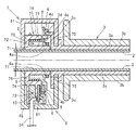
- the position detection device 1 is provided on a handlebar 2 of a motorcycle (not shown), and rotates according to a rotation operation of a handle grip 3 that is an operation unit that is rotatably provided on the handlebar 2.
- the rotating member 4, the detected portion 5 fixed to the rotating member 4, the detecting portion 6 for detecting the detected portion 5, and the detecting portion 5 are supported while being rotatably supported.
- a fixed support member 7 and a housing 8 that houses the detected portion 5 and the detecting portion 6 are provided.
- the handle bar 2 is made of a metal such as iron or aluminum and is a cylindrical bar-shaped member.
- the handle grip 3 includes a sleeve 3a and a grip portion 3b.
- the sleeve 3a has a cylindrical shape made of synthetic resin, and is rotatably positioned on the outer periphery of the handle bar 2.
- the sleeve 3a includes a flange 3c at the left end in FIG.
- the flange portion 3c has a disk shape and is provided on the outer periphery of the handle grip 3 without any breaks.
- a part of the edge is provided with a connecting part 3 d that is connected to the detected part 5 and transmits the rotation of the handle grip 3.
- the grip portion 3b is a portion that is gripped by the driver, is made of an elastic member such as rubber, covers the outer periphery of the sleeve 3a seamlessly, and is firmly fixed to the sleeve 3a.
- the rotating member 4 is made of a synthetic resin material, and a cylindrical portion described later provided in the supporting member 7 is inserted therethrough, and a cylindrical sliding portion 4a that slides on the outer periphery of the cylindrical portion is provided. 7 is rotatably supported.
- the cylindrical sliding portion 4a (one end portion thereof) is provided with a flange portion 4b formed outward.
- the detected portion 5 is disposed on the flange portion 4b.
- the rotating member 4 includes a holding portion 4c that holds one end of a return spring described later.
- the rotating member 4 includes a receiving portion 4d formed of a recess into which the connecting portion 3d provided on the handle grip 3 is inserted. By inserting the connecting portion 3d of the handle grip 3 into the receiving portion 4d, the rotation of the handle grip 3 is transmitted to the rotating member 4, and the detected portion 5 is rotated.
- the detected part 5 includes a plurality of detected objects 5a made of a metal that is hard to be magnetized, such as copper, on an insulating member made of a material obtained by impregnating glass fiber or paper with an epoxy resin or a phenol resin and hardened in a plate shape. Is the substrate 5b.
- the object to be detected 5a is a copper foil with thin copper, and is arranged in an arc shape at the same angle and the same distance, and is insulated as a protective film on the surface so as to protect the surface from dirt such as moisture and dust. Resin (resist) is applied or pasted.
- the detection unit 6 includes two pairs of detection coils on the silicon wafer, detects currents induced in the detection coils due to a magnetic change accompanying the rotation of the detection target 5a, and The position moved is detected.
- the detection unit 6 is mounted on the circuit board 61.
- the detection unit 6 is disposed to face the substrate 5b and detects the rotation of the substrate 5b.
- the circuit board 61 is provided with a conductive path (not shown) or an electronic component electrically connected to the conductive path on an insulating base material such as glass epoxy resin.
- the detection unit 6 is electrically connected to the circuit board 61.
- the circuit board 61 is electrically connected to a wiring 54 connected to an external circuit. A signal from the detection unit 6 is output to an external circuit via the circuit board 61 and the wiring 54.
- the support member 7 is made of a synthetic resin, is a ring-shaped cylindrical portion 71 having a hole through which the handle bar 2 passes, and surrounds the outer periphery of the handle bar 2.
- the support member 7 is fixed to the handlebar 2 so as not to rotate by means not shown.
- the supporting member 7 supports the rotating member 4 by the cylindrical portion 71 so as to be rotatable.
- the support member 7 holds the first holding portion 72 that holds the return spring 9 (coil spring) that returns the handle grip 3 to the initial position, and the detection portion 6 so as to face the detected body 5a of the substrate 5b. And a second holding unit 73.
- the first holding part 72 is provided with a second cylindrical part 74 outside the cylindrical part 71, and the cylindrical part 71 and the second cylindrical part 74 are connected by a connecting part 76 on the left side in FIG. It is formed and constitutes a storage portion that stores at least a part of the return spring 9.
- the return spring 9 is a coil spring formed of a spring metal material and mainly formed in a spiral shape, and returns the handlebar grip 3 operated by the driver to an initial position.
- the return spring 9 is arranged such that the tubular portion 71 is located on the inner side and the second tubular portion 74 is located on the outer side.
- the second cylindrical portion 74 is provided with a notch in a not-shown portion, and one end of the return spring 9 is held in this notch.
- the support member 7 has a retaining member 75 attached to the right side of the cylindrical portion 71 in FIG.
- the retaining member 75 prevents the detected portion 5 from falling off from the tubular portion 71 and is pressed to the right side in FIG. 2 by the return spring 9 in the rotational axis direction of the handle grip 3 of the rotational member 4.
- the movement of the rotating member 4 is restricted.
- the return spring 9 returns the handle grip 3 operated by the driver to the initial position.
- the second holding unit 73 is a storage unit that stores at least a part of the detection unit 6.
- the second holding unit 73 is provided outside the second cylindrical unit 74 and stores the circuit board 61 on which the detection unit 6 is mounted. To do. It is fixed by the filling member 10 filled in the second holding portion 73.
- the filling member 10 is made of a thermoplastic resin such as an epoxy resin or a urethane resin, and fixes the detection unit 6 disposed on the second holding unit 73 and the circuit board 61, and enters from the outside such as water and dust.
- the second holding portion 73 is filled so as to be insulated from the object.
- the housing 8 is composed of first and second housings 81 and 82. Both the first and second housings 81 and 82 are made of various metal materials such as a non-magnetic metal material such as aluminum or synthetic resin, and have a substantially semicircular cup shape. The first and second housings 81 and 82 are divided along the direction of the rotation center axis of the handle grip 3. The first and second housings 81 and 82 are fixed by appropriate means such as welding.
- the housing 8 accommodates the detected part 5, the detection part 6, and the support member 7.
- the housing 8 is fixed so as not to rotate with respect to the handle bar 2 by means (not shown).
- the present invention can be used for a position detection device that detects an operation position of an operation means such as a handle grip of a motorcycle.
- Position detection device 3 Handle grip (operation part) DESCRIPTION OF SYMBOLS 4 Rotating member 4a Sliding part 5 Detected part 5a Detected object 5b Substrate 6 Detecting part 7 Supporting member 8 Housing 9 Return spring 10 Filling member 61 Circuit board 72 First holding part 73 Second holding part
Landscapes
- Physics & Mathematics (AREA)
- General Physics & Mathematics (AREA)
- Measurement Of Length, Angles, Or The Like Using Electric Or Magnetic Means (AREA)
- Transmission And Conversion Of Sensor Element Output (AREA)
Abstract
外部磁界に影響されず検出精度への影響を抑えることが可能な位置検出装置を提供する。 ハンドルバー2に回動可能に設けた操作部3の回動操作に応じて回動する回動部材4と、回動部材4に固定された被検出部5と、被検出部5を検出する検出部6と、被検出部5と検出部6とを収納するハウジング8と、を備えた位置検出装置1において、被検出部5は、軟磁性体の金属からなる複数の被検出体5aが円弧状に設けられた基板5bからなり、検出部6は、基板5bに対向配置され基板5bの回動を検出するものである。
Description
本発明は、二輪車のハンドルグリップ等の操作手段の操作位置を検出する位置検出装置に関するものである。
従来の位置検出器は、二輪車のハンドルバーに回動可能に取り付けられたハンドルグリップと、このハンドルグリップの回動操作に同期して回動し磁石や磁性体からなる被検出部である閉磁気回路を備えた移動部材と、前記閉磁気回路に生じる漏洩磁界を検出する検出部である磁気検出部と、この磁気検出部を搭載した回路基板と、前記移動部材や磁気検出部や回路基板等を収納する枠体とを備えたものであった(例えば、特許文献1を参照)。
従来の位置検出装置では、被検出部に磁石や磁性体を採用し、検出部に磁気検出部を採用しているため、運転者が身に着けているアクセサリー類に起因する外部磁界や、磁性体である鉄系材料からなるハンドルバーの磁性に起因して、閉磁気回路に歪みが生じ、前記検出部の検出精度が低下してしまうおそれがあった。
そこで、本発明は前述した問題点に着目し、外部磁界に影響されず検出精度への影響を抑えることが可能な位置検出装置を提供することを目的とする。
本発明における位置検出装置は、回動可能に設けた操作部の回動操作に応じて回動する回動部材と、前記回動部材に固定された被検出部と、前記被検出部を検出する検出部と、前記被検出部と前記検出部とを収納するハウジングと、を備えた位置検出装置において、前記被検出部は、軟磁性体の金属からなる複数の被検出体が円弧状に設けられた基板からなり、前記検出部は、前記基板に対向配置され前記基板の回動を検出するものである。
また、軟磁性体の金属が、銅である。
また、前記銅を保護する保護膜を設けたものである。
また、前記回動部材を回転可能に支持する支持部材を設け、この支持部材は前記操作部を初期位置に復帰させるリターンバネを保持する第1の保持部と、前記検出部が前記基板の前記被検出体に対向配置するように保持する第2の保持部とを備えてなるものである。
また、前記第1の保持部は、前記リターンバネの少なくとも一部を収納する収納部である。
また、前記第2の保持部は、前記検出部の少なくとも一部を収納する収納部である。
また、前記検出部は回路基板に実装され、前記回路基板は前記第2の保持部内に充填される充填部材にて固定されるものである。
以上のように本発明によれば、外部磁界に影響されず検出精度への影響を抑えることが可能な位置検出装置を提供することができる。
以下、添付図面に基づいて、本発明の第1実施形態を、二輪車のハンドルバーに回動可能に設けられた操作部であるハンドルグリップの操作位置(回動角)を検出する位置検出装置を例にとって説明する。
本発明の位置検出装置1は、図示しない二輪車のハンドルバー2に設けられるものであり、ハンドルバー2に回動可能に設けた操作部であるハンドルグリップ3の回動操作に応じて回動する回動部材4と、この回動部材4に固定された被検出部5と、この被検出部5を検出する検出部6と、被検出部5を回動可能に支持するとともに検出部6を固定した支持部材7と、被検出部5と検出部6とを収納するハウジング8とを備えている。
ハンドルバー2は、鉄やアルミニウム等の金属からなり、円筒の棒状部材である。
ハンドルグリップ3は、スリーブ3aとグリップ部3bとで構成されており、スリーブ3aは、合成樹脂からなる円筒形状で、ハンドルバー2の外周に回動自在に位置している。スリーブ3aは、図3中左側の端部に、鍔部3cを備えている。鍔部3cは円盤形状で、ハンドルグリップ3の外周に切れ目なく設けられている。そして、その縁の一部に、被検出部5と連結し、ハンドルグリップ3の回動を伝達する連結部3dを備えている。
グリップ部3bは、運転者が握る部分であり、ゴム等の弾性部材からなり、スリーブ3aの外周を切れ目なく覆っており、スリーブ3aに強固に固定されている。
回動部材4は、合成樹脂材料からなり、支持部材7に設けた後述する筒状部が挿通し、前記筒状部の外周を摺動する筒状の摺動部4aが設けられ、支持部材7に回動可能に支持されている。筒状の摺動部4a(の一方の端部)には外方に形成されたフランジ部4bが、設けられている。また、このフランジ部4bには、被検出部5が配置される。また、回動部材4には、後述するリターンバネの一端を保持する保持部4cを備えている。回動部材4には、ハンドルグリップ3に設けた連結部3dが挿入される凹みからなる受け部4dを備えている。ハンドルグリップ3の連結部3dを受け部4dに挿入することによって、ハンドルグリップ3の回動が、回動部材4に伝わり、被検出部5が回動するものである。
被検出部5は、ガラス繊維や紙にエポキシ樹脂やフェノール樹脂を含浸させ、硬質に板状に固めた材料からなる絶縁部材に、磁化しにくい金属、例えば、銅からなる複数の被検出体5aが設けられた基板5bである。被検出体5aは、銅を薄く設けた銅箔であり、円弧状に同一角度、同一距離で均等に配設され、水分や塵埃などの汚れから表面を保護するように表面に保護膜として絶縁樹脂(レジスト)を塗布あるいは貼付けされている。
検出部6は、シリコンウェハ上に1対の検出コイルを2組備え、被検出体5aの回動に伴う磁気変化により前記各検出コイルに誘導される電流を検出し、被検出部5の回動した位置を検出するものである。
検出部6は、回路基板61に実装されている。検出部6は、基板5bに対向配置され、基板5bの回動を検出する。
回路基板61は、ガラスエポキシ樹脂等の絶縁性の基材に図示しない導電路やこの導電路と電気的に接続された電子部品等を備えたものである。検出部6は、回路基板61に電気的に接続されている。また、回路基板61には、外部回路に接続された配線54が電気的に接続されている。検出部6の信号は、回路基板61と配線54を介して外部の回路に出力される。
支持部材7は、合成樹脂からなり、環状で、ハンドルバー2が貫通する孔を備えた筒状部71であり、ハンドルバー2の外周を取り囲んでいる。そして、支持部材7は、ハンドルバー2に対して、図示しない手段によって回動しないように固定されている。支持部材7は、筒状部71で回動部材4を回動可能に支持している。
支持部材7は、ハンドルグリップ3を初期位置に復帰させるリターンバネ9(コイルバネ)を保持する第1の保持部72と、検出部6を基板5bの被検出体5aに対向配置するように保持する第2の保持部73とを備えている。
第1の保持部72は、筒状部71の外側に第2の筒状部74を設け、筒状部71と第2の筒状部74を図2中左側の連結部76で接続し、形成したものであり、リターンバネ9の少なくとも一部を収納する収納部を構成している。リターンバネ9は、バネ性金属材料の線材から形成され、主に螺旋形状で形成されるコイルバネであり、運転者によって操作されたハンドルグリップ3を初期の位置に復帰させるものである。リターンバネ9は、筒状部71が内側に、第2の筒状部74が外側に位置するように、配置されている。なお、第2の筒状部74には、図示しない部分に切り欠きを備えており、この切り欠きにリターンバネ9の一端を保持している。
また、支持部材7は、図2中、筒状部71の右側に、抜止部材75が取り付けられている。この抜止部材75は、被検出部5の筒状部71からの脱落を防止するとともに、回動部材4のハンドルグリップ3の回動軸方向において、リターンバネ9によって、図2中右側へ押し付けられている回動部材4の移動を規制するものである。なお、リターンバネ9は、運転者によって操作されたハンドルグリップ3を初期の位置に復帰させるものである。
第2の保持部73は、検出部6の少なくとも一部を収納する収納部であり、第2の筒状部74の外側に設けられており、検出部6が実装された回路基板61を収納するものである。この第2の保持部73に充填される充填部材10にて固定されている。
充填部材10は、エポキシ樹脂やウレタン樹脂などの熱可塑性樹脂からなり、第2の保持部73に配設された検出部6と回路基板61とを固定するとともに、水や塵埃など外部からの侵入物から絶縁するように第2の保持部73に充填されるものである。
充填部材10は、エポキシ樹脂やウレタン樹脂などの熱可塑性樹脂からなり、第2の保持部73に配設された検出部6と回路基板61とを固定するとともに、水や塵埃など外部からの侵入物から絶縁するように第2の保持部73に充填されるものである。
ハウジング8は、第1、第2のハウジング81、82とから構成されている。第1、第2のハウジング81、82とも、アルミニウム等の非磁性金属材料をはじめとする各種金属材料もしくは合成樹脂製で、およそ半円形状のカップ形状である。第1、第2のハウジング81、82は、ハンドルグリップ3の回動中心軸方向に沿って分割するものである。第1、第2のハウジング81、82は溶着等の適宜手段によって固定されている。
ハウジング8は、被検出部5と検出部6と支持部材7を収納するものである。ハウジング8は、ハンドルバー2に対して図示しない手段によって回動しないように固定されている。
以上の構成によって、外部磁界に影響されず検出精度への影響を抑えることができる。
本発明は、二輪車のハンドルグリップ等の操作手段の操作位置を検出する位置検出装置に利用可能である。
1 位置検出装置
3 ハンドルグリップ(操作部)
4 回動部材
4a 摺動部
5 被検出部
5a 被検出体
5b 基板
6 検出部
7 支持部材
8 ハウジング
9 リターンバネ
10 充填部材
61 回路基板
72 第1の保持部
73 第2の保持部
3 ハンドルグリップ(操作部)
4 回動部材
4a 摺動部
5 被検出部
5a 被検出体
5b 基板
6 検出部
7 支持部材
8 ハウジング
9 リターンバネ
10 充填部材
61 回路基板
72 第1の保持部
73 第2の保持部
Claims (7)
- 回動可能に設けた操作部の回動操作に応じて回動する回動部材と、前記回動部材に固定された被検出部と、前記被検出部を検出する検出部と、前記被検出部と前記検出部とを収納するハウジングと、を備えた位置検出装置において、前記被検出部は、軟磁性体の金属からなる複数の被検出体が円弧状に設けられた基板からなり、前記検出部は、前記基板に対向配置され前記基板の回動を検出することを特徴とする位置検出装置。
- 軟磁性体の金属が、銅であることを特徴とする請求項1に記載の位置検出装置。
- 前記銅を保護する保護膜を設けたことを特徴とする請求項2に記載の位置検出装置。
- 前記回動部材を回転可能に支持する支持部材を設け、この支持部材は前記操作部を初期位置に復帰させるリターンバネを保持する第1の保持部と、前記検出部が前記基板の前記被検出体に対向配置するように保持する第2の保持部とを備えてなることを特徴とする請求項1に記載の位置検出装置。
- 前記第1の保持部は、前記リターンバネの少なくとも一部を収納する収納部であることを特徴とする請求項4に記載の位置検出装置。
- 前記第2の保持部は、前記検出部の少なくとも一部を収納する収納部であることを特徴とする請求項4に記載の位置検出装置。
- 前記検出部は回路基板に実装され、前記回路基板は前記第2の保持部内に充填される充填部材にて固定されることを特徴とする請求項6に記載の位置検出装置。
Priority Applications (2)
| Application Number | Priority Date | Filing Date | Title |
|---|---|---|---|
| CN201280024644.3A CN103547891A (zh) | 2011-05-30 | 2012-03-12 | 位置检测装置 |
| EP12793621.9A EP2717023A4 (en) | 2011-05-30 | 2012-03-12 | POSITION DETECTION DEVICE |
Applications Claiming Priority (2)
| Application Number | Priority Date | Filing Date | Title |
|---|---|---|---|
| JP2011-120389 | 2011-05-30 | ||
| JP2011120389A JP2012247352A (ja) | 2011-05-30 | 2011-05-30 | 位置検出装置 |
Publications (1)
| Publication Number | Publication Date |
|---|---|
| WO2012164995A1 true WO2012164995A1 (ja) | 2012-12-06 |
Family
ID=47258861
Family Applications (1)
| Application Number | Title | Priority Date | Filing Date |
|---|---|---|---|
| PCT/JP2012/056231 Ceased WO2012164995A1 (ja) | 2011-05-30 | 2012-03-12 | 位置検出装置 |
Country Status (4)
| Country | Link |
|---|---|
| EP (1) | EP2717023A4 (ja) |
| JP (1) | JP2012247352A (ja) |
| CN (1) | CN103547891A (ja) |
| WO (1) | WO2012164995A1 (ja) |
Cited By (1)
| Publication number | Priority date | Publication date | Assignee | Title |
|---|---|---|---|---|
| CN104048832A (zh) * | 2013-03-13 | 2014-09-17 | 中华人民共和国昆山出入境检验检疫局 | 一种自行车车把转角灵活性测试装置 |
Families Citing this family (2)
| Publication number | Priority date | Publication date | Assignee | Title |
|---|---|---|---|---|
| JP6435811B2 (ja) * | 2014-11-28 | 2018-12-12 | 村田機械株式会社 | 磁気式位置検出装置 |
| JP7312998B2 (ja) * | 2019-01-29 | 2023-07-24 | 朝日電装株式会社 | スロットルグリップ装置 |
Citations (5)
| Publication number | Priority date | Publication date | Assignee | Title |
|---|---|---|---|---|
| JPH02264803A (ja) * | 1989-01-17 | 1990-10-29 | Gec Alsthom Sa | 回転鋼鉄シャフトの位置を測定する装置及びそのためのトラックの製造方法 |
| US20040216550A1 (en) * | 2003-04-04 | 2004-11-04 | Klaus Fallak | Electronic throttle control system for motorcycles |
| JP2005531779A (ja) * | 2002-07-02 | 2005-10-20 | アクチボラゲット エス ケイ エフ | 計測機能付きころがり軸受及びこれを備えた電動機 |
| JP2007187540A (ja) * | 2006-01-13 | 2007-07-26 | Nippon Seiki Co Ltd | 角度検出器 |
| JP2009098005A (ja) | 2007-10-17 | 2009-05-07 | Nippon Seiki Co Ltd | 位置検出器 |
Family Cites Families (5)
| Publication number | Priority date | Publication date | Assignee | Title |
|---|---|---|---|---|
| US6956368B2 (en) * | 1998-05-08 | 2005-10-18 | Wabash Technologies, Inc. | Magnetic rotational position sensor |
| FR2790549B1 (fr) * | 1999-03-03 | 2001-04-13 | Moving Magnet Tech | Capteur de position a sonde magneto-sensible et aimant encastre dans le fer |
| JP4476717B2 (ja) * | 2004-06-30 | 2010-06-09 | オークマ株式会社 | 電磁誘導型位置センサ |
| DE102006046531A1 (de) * | 2006-09-29 | 2008-04-03 | Dr. Johannes Heidenhain Gmbh | Drehgeber und Verfahren zu dessen Betrieb |
| US8085036B2 (en) * | 2009-01-14 | 2011-12-27 | Infineon Technologies Ag | Sensor including two code rings and a magnetic field sensor between the code rings |
-
2011
- 2011-05-30 JP JP2011120389A patent/JP2012247352A/ja active Pending
-
2012
- 2012-03-12 EP EP12793621.9A patent/EP2717023A4/en not_active Withdrawn
- 2012-03-12 CN CN201280024644.3A patent/CN103547891A/zh active Pending
- 2012-03-12 WO PCT/JP2012/056231 patent/WO2012164995A1/ja not_active Ceased
Patent Citations (5)
| Publication number | Priority date | Publication date | Assignee | Title |
|---|---|---|---|---|
| JPH02264803A (ja) * | 1989-01-17 | 1990-10-29 | Gec Alsthom Sa | 回転鋼鉄シャフトの位置を測定する装置及びそのためのトラックの製造方法 |
| JP2005531779A (ja) * | 2002-07-02 | 2005-10-20 | アクチボラゲット エス ケイ エフ | 計測機能付きころがり軸受及びこれを備えた電動機 |
| US20040216550A1 (en) * | 2003-04-04 | 2004-11-04 | Klaus Fallak | Electronic throttle control system for motorcycles |
| JP2007187540A (ja) * | 2006-01-13 | 2007-07-26 | Nippon Seiki Co Ltd | 角度検出器 |
| JP2009098005A (ja) | 2007-10-17 | 2009-05-07 | Nippon Seiki Co Ltd | 位置検出器 |
Non-Patent Citations (1)
| Title |
|---|
| See also references of EP2717023A4 * |
Cited By (1)
| Publication number | Priority date | Publication date | Assignee | Title |
|---|---|---|---|---|
| CN104048832A (zh) * | 2013-03-13 | 2014-09-17 | 中华人民共和国昆山出入境检验检疫局 | 一种自行车车把转角灵活性测试装置 |
Also Published As
| Publication number | Publication date |
|---|---|
| EP2717023A4 (en) | 2014-12-24 |
| CN103547891A (zh) | 2014-01-29 |
| EP2717023A1 (en) | 2014-04-09 |
| JP2012247352A (ja) | 2012-12-13 |
Similar Documents
| Publication | Publication Date | Title |
|---|---|---|
| CN102472636B (zh) | 霍尔效应感应装置 | |
| JP7270614B2 (ja) | モータビークルの回転ハンドルを検出するためのモジュール | |
| US8896299B2 (en) | Position detector device capable of reducing the effect of external magnetic fields on precision in detection | |
| WO2011065224A1 (ja) | 位置検出装置 | |
| US10176944B2 (en) | Rotational movement detection device | |
| WO2012164995A1 (ja) | 位置検出装置 | |
| KR101775165B1 (ko) | 트랙션 모터 | |
| JP2011111011A (ja) | サイドスタンドの位置検出装置 | |
| JP5041401B2 (ja) | 回転センサ | |
| EP3494367B1 (en) | Magnetic angular position sensor | |
| JP2009085913A (ja) | 位置検出器 | |
| JP2009098005A (ja) | 位置検出器 | |
| JP2010151731A (ja) | 位置検出装置 | |
| WO2010071067A1 (ja) | 位置検出装置 | |
| JP6276121B2 (ja) | 回転移動検出装置 | |
| JP2011169760A (ja) | 角度検出器 | |
| JP2012137353A (ja) | 位置検出装置 | |
| JP5679453B2 (ja) | 変位検出装置 | |
| JP6201629B2 (ja) | 車両用検出装置 | |
| JP2021165699A (ja) | 磁石ユニット及び位置検出装置 | |
| JP2012073050A (ja) | 位置検出装置 | |
| JP2022178383A (ja) | 磁気センサユニット | |
| JP2012021901A (ja) | 角度検出器 |
Legal Events
| Date | Code | Title | Description |
|---|---|---|---|
| 121 | Ep: the epo has been informed by wipo that ep was designated in this application |
Ref document number: 12793621 Country of ref document: EP Kind code of ref document: A1 |
|
| WWE | Wipo information: entry into national phase |
Ref document number: 2012793621 Country of ref document: EP |
|
| NENP | Non-entry into the national phase |
Ref country code: DE |