WO2012164995A1 - Appareil de détection de position - Google Patents
Appareil de détection de position Download PDFInfo
- Publication number
- WO2012164995A1 WO2012164995A1 PCT/JP2012/056231 JP2012056231W WO2012164995A1 WO 2012164995 A1 WO2012164995 A1 WO 2012164995A1 JP 2012056231 W JP2012056231 W JP 2012056231W WO 2012164995 A1 WO2012164995 A1 WO 2012164995A1
- Authority
- WO
- WIPO (PCT)
- Prior art keywords
- unit
- detected
- substrate
- position detection
- detection
- Prior art date
- Legal status (The legal status is an assumption and is not a legal conclusion. Google has not performed a legal analysis and makes no representation as to the accuracy of the status listed.)
- Ceased
Links
Images


Classifications
-
- G—PHYSICS
- G01—MEASURING; TESTING
- G01B—MEASURING LENGTH, THICKNESS OR SIMILAR LINEAR DIMENSIONS; MEASURING ANGLES; MEASURING AREAS; MEASURING IRREGULARITIES OF SURFACES OR CONTOURS
- G01B7/00—Measuring arrangements characterised by the use of electric or magnetic techniques
- G01B7/30—Measuring arrangements characterised by the use of electric or magnetic techniques for measuring angles or tapers; for testing the alignment of axes
-
- G—PHYSICS
- G01—MEASURING; TESTING
- G01D—MEASURING NOT SPECIALLY ADAPTED FOR A SPECIFIC VARIABLE; ARRANGEMENTS FOR MEASURING TWO OR MORE VARIABLES NOT COVERED IN A SINGLE OTHER SUBCLASS; TARIFF METERING APPARATUS; MEASURING OR TESTING NOT OTHERWISE PROVIDED FOR
- G01D5/00—Mechanical means for transferring the output of a sensing member; Means for converting the output of a sensing member to another variable where the form or nature of the sensing member does not constrain the means for converting; Transducers not specially adapted for a specific variable
- G01D5/12—Mechanical means for transferring the output of a sensing member; Means for converting the output of a sensing member to another variable where the form or nature of the sensing member does not constrain the means for converting; Transducers not specially adapted for a specific variable using electric or magnetic means
- G01D5/14—Mechanical means for transferring the output of a sensing member; Means for converting the output of a sensing member to another variable where the form or nature of the sensing member does not constrain the means for converting; Transducers not specially adapted for a specific variable using electric or magnetic means influencing the magnitude of a current or voltage
- G01D5/20—Mechanical means for transferring the output of a sensing member; Means for converting the output of a sensing member to another variable where the form or nature of the sensing member does not constrain the means for converting; Transducers not specially adapted for a specific variable using electric or magnetic means influencing the magnitude of a current or voltage by varying inductance, e.g. by a movable armature
- G01D5/204—Mechanical means for transferring the output of a sensing member; Means for converting the output of a sensing member to another variable where the form or nature of the sensing member does not constrain the means for converting; Transducers not specially adapted for a specific variable using electric or magnetic means influencing the magnitude of a current or voltage by varying inductance, e.g. by a movable armature by influencing the mutual induction between two or more coils
- G01D5/2046—Mechanical means for transferring the output of a sensing member; Means for converting the output of a sensing member to another variable where the form or nature of the sensing member does not constrain the means for converting; Transducers not specially adapted for a specific variable using electric or magnetic means influencing the magnitude of a current or voltage by varying inductance, e.g. by a movable armature by influencing the mutual induction between two or more coils by a movable ferromagnetic element, e.g. a core
-
- G—PHYSICS
- G01—MEASURING; TESTING
- G01D—MEASURING NOT SPECIALLY ADAPTED FOR A SPECIFIC VARIABLE; ARRANGEMENTS FOR MEASURING TWO OR MORE VARIABLES NOT COVERED IN A SINGLE OTHER SUBCLASS; TARIFF METERING APPARATUS; MEASURING OR TESTING NOT OTHERWISE PROVIDED FOR
- G01D5/00—Mechanical means for transferring the output of a sensing member; Means for converting the output of a sensing member to another variable where the form or nature of the sensing member does not constrain the means for converting; Transducers not specially adapted for a specific variable
- G01D5/12—Mechanical means for transferring the output of a sensing member; Means for converting the output of a sensing member to another variable where the form or nature of the sensing member does not constrain the means for converting; Transducers not specially adapted for a specific variable using electric or magnetic means
- G01D5/244—Mechanical means for transferring the output of a sensing member; Means for converting the output of a sensing member to another variable where the form or nature of the sensing member does not constrain the means for converting; Transducers not specially adapted for a specific variable using electric or magnetic means influencing characteristics of pulses or pulse trains; generating pulses or pulse trains
- G01D5/24428—Error prevention
Definitions
- the present invention relates to a position detection device that detects an operation position of an operation means such as a handle grip of a motorcycle.
- a conventional position detector includes a handle grip that is rotatably attached to a handlebar of a two-wheeled vehicle, and a closed magnet that is a detected portion made of a magnet or a magnetic material that rotates in synchronization with the rotation operation of the handle grip.
- a moving member having a circuit, a magnetic detection unit that is a detection unit for detecting a leakage magnetic field generated in the closed magnetic circuit, a circuit board on which the magnetic detection unit is mounted, the moving member, the magnetic detection unit, the circuit board, and the like (For example, refer patent document 1).
- the present invention pays attention to the above-described problems, and an object thereof is to provide a position detection device capable of suppressing the influence on the detection accuracy without being influenced by the external magnetic field.
- the position detection device detects a rotation member that rotates according to a rotation operation of an operation unit that is rotatably provided, a detected portion that is fixed to the rotation member, and the detected portion. And a housing that houses the detected portion and the detecting portion, wherein the detected portion includes a plurality of detected objects made of a soft magnetic metal in an arc shape.
- the detection unit is arranged to face the substrate and detects the rotation of the substrate.
- the soft magnetic metal is copper.
- a protective film for protecting the copper is provided.
- a support member that rotatably supports the rotating member.
- the support member includes a first holding unit that holds a return spring that returns the operation unit to an initial position, and the detection unit is provided on the substrate. And a second holding unit that holds the object to be detected so as to face the object to be detected.
- the first holding portion is a storage portion that stores at least a part of the return spring.
- the second holding unit is a storage unit that stores at least a part of the detection unit.
- the detection unit is mounted on a circuit board, and the circuit board is fixed by a filling member filled in the second holding unit.
- a position detecting device for detecting an operation position (rotation angle) of a handle grip which is an operation unit rotatably provided on a handlebar of a two-wheeled vehicle, will be described. Let's take an example.
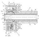
- the position detection device 1 is provided on a handlebar 2 of a motorcycle (not shown), and rotates according to a rotation operation of a handle grip 3 that is an operation unit that is rotatably provided on the handlebar 2.
- the rotating member 4, the detected portion 5 fixed to the rotating member 4, the detecting portion 6 for detecting the detected portion 5, and the detecting portion 5 are supported while being rotatably supported.
- a fixed support member 7 and a housing 8 that houses the detected portion 5 and the detecting portion 6 are provided.
- the handle bar 2 is made of a metal such as iron or aluminum and is a cylindrical bar-shaped member.
- the handle grip 3 includes a sleeve 3a and a grip portion 3b.
- the sleeve 3a has a cylindrical shape made of synthetic resin, and is rotatably positioned on the outer periphery of the handle bar 2.
- the sleeve 3a includes a flange 3c at the left end in FIG.
- the flange portion 3c has a disk shape and is provided on the outer periphery of the handle grip 3 without any breaks.
- a part of the edge is provided with a connecting part 3 d that is connected to the detected part 5 and transmits the rotation of the handle grip 3.
- the grip portion 3b is a portion that is gripped by the driver, is made of an elastic member such as rubber, covers the outer periphery of the sleeve 3a seamlessly, and is firmly fixed to the sleeve 3a.
- the rotating member 4 is made of a synthetic resin material, and a cylindrical portion described later provided in the supporting member 7 is inserted therethrough, and a cylindrical sliding portion 4a that slides on the outer periphery of the cylindrical portion is provided. 7 is rotatably supported.
- the cylindrical sliding portion 4a (one end portion thereof) is provided with a flange portion 4b formed outward.
- the detected portion 5 is disposed on the flange portion 4b.
- the rotating member 4 includes a holding portion 4c that holds one end of a return spring described later.
- the rotating member 4 includes a receiving portion 4d formed of a recess into which the connecting portion 3d provided on the handle grip 3 is inserted. By inserting the connecting portion 3d of the handle grip 3 into the receiving portion 4d, the rotation of the handle grip 3 is transmitted to the rotating member 4, and the detected portion 5 is rotated.
- the detected part 5 includes a plurality of detected objects 5a made of a metal that is hard to be magnetized, such as copper, on an insulating member made of a material obtained by impregnating glass fiber or paper with an epoxy resin or a phenol resin and hardened in a plate shape. Is the substrate 5b.
- the object to be detected 5a is a copper foil with thin copper, and is arranged in an arc shape at the same angle and the same distance, and is insulated as a protective film on the surface so as to protect the surface from dirt such as moisture and dust. Resin (resist) is applied or pasted.
- the detection unit 6 includes two pairs of detection coils on the silicon wafer, detects currents induced in the detection coils due to a magnetic change accompanying the rotation of the detection target 5a, and The position moved is detected.
- the detection unit 6 is mounted on the circuit board 61.
- the detection unit 6 is disposed to face the substrate 5b and detects the rotation of the substrate 5b.
- the circuit board 61 is provided with a conductive path (not shown) or an electronic component electrically connected to the conductive path on an insulating base material such as glass epoxy resin.
- the detection unit 6 is electrically connected to the circuit board 61.
- the circuit board 61 is electrically connected to a wiring 54 connected to an external circuit. A signal from the detection unit 6 is output to an external circuit via the circuit board 61 and the wiring 54.
- the support member 7 is made of a synthetic resin, is a ring-shaped cylindrical portion 71 having a hole through which the handle bar 2 passes, and surrounds the outer periphery of the handle bar 2.
- the support member 7 is fixed to the handlebar 2 so as not to rotate by means not shown.
- the supporting member 7 supports the rotating member 4 by the cylindrical portion 71 so as to be rotatable.
- the support member 7 holds the first holding portion 72 that holds the return spring 9 (coil spring) that returns the handle grip 3 to the initial position, and the detection portion 6 so as to face the detected body 5a of the substrate 5b. And a second holding unit 73.
- the first holding part 72 is provided with a second cylindrical part 74 outside the cylindrical part 71, and the cylindrical part 71 and the second cylindrical part 74 are connected by a connecting part 76 on the left side in FIG. It is formed and constitutes a storage portion that stores at least a part of the return spring 9.
- the return spring 9 is a coil spring formed of a spring metal material and mainly formed in a spiral shape, and returns the handlebar grip 3 operated by the driver to an initial position.
- the return spring 9 is arranged such that the tubular portion 71 is located on the inner side and the second tubular portion 74 is located on the outer side.
- the second cylindrical portion 74 is provided with a notch in a not-shown portion, and one end of the return spring 9 is held in this notch.
- the support member 7 has a retaining member 75 attached to the right side of the cylindrical portion 71 in FIG.
- the retaining member 75 prevents the detected portion 5 from falling off from the tubular portion 71 and is pressed to the right side in FIG. 2 by the return spring 9 in the rotational axis direction of the handle grip 3 of the rotational member 4.
- the movement of the rotating member 4 is restricted.
- the return spring 9 returns the handle grip 3 operated by the driver to the initial position.
- the second holding unit 73 is a storage unit that stores at least a part of the detection unit 6.
- the second holding unit 73 is provided outside the second cylindrical unit 74 and stores the circuit board 61 on which the detection unit 6 is mounted. To do. It is fixed by the filling member 10 filled in the second holding portion 73.
- the filling member 10 is made of a thermoplastic resin such as an epoxy resin or a urethane resin, and fixes the detection unit 6 disposed on the second holding unit 73 and the circuit board 61, and enters from the outside such as water and dust.
- the second holding portion 73 is filled so as to be insulated from the object.
- the housing 8 is composed of first and second housings 81 and 82. Both the first and second housings 81 and 82 are made of various metal materials such as a non-magnetic metal material such as aluminum or synthetic resin, and have a substantially semicircular cup shape. The first and second housings 81 and 82 are divided along the direction of the rotation center axis of the handle grip 3. The first and second housings 81 and 82 are fixed by appropriate means such as welding.
- the housing 8 accommodates the detected part 5, the detection part 6, and the support member 7.
- the housing 8 is fixed so as not to rotate with respect to the handle bar 2 by means (not shown).
- the present invention can be used for a position detection device that detects an operation position of an operation means such as a handle grip of a motorcycle.
- Position detection device 3 Handle grip (operation part) DESCRIPTION OF SYMBOLS 4 Rotating member 4a Sliding part 5 Detected part 5a Detected object 5b Substrate 6 Detecting part 7 Supporting member 8 Housing 9 Return spring 10 Filling member 61 Circuit board 72 First holding part 73 Second holding part
Landscapes
- Physics & Mathematics (AREA)
- General Physics & Mathematics (AREA)
- Measurement Of Length, Angles, Or The Like Using Electric Or Magnetic Means (AREA)
- Transmission And Conversion Of Sensor Element Output (AREA)
Abstract
La présente invention concerne un appareil de détection de position, dont la précision de détection n'est pas affectée par un champ magnétique externe. L'appareil de détection de position (1) comprend : un organe rotatif (4) tournant selon les opérations de rotation d'une unité de commande (3) fixée rotative sur un guidon (2) ; une unité à détecter (5) qui est fixée sur l'organe rotatif (4) ; une unité de détection (6) qui détecte l'unité à détecter (5) ; et un logement (8) qui contient l'unité à détecter (5) et l'unité de détection (6). L'unité à détecter (5) est composée d'un substrat (5b) comportant une pluralité de corps à détecter (5a), lesdits corps étant composés d'un métal magnétique doux et disposés en arc, et l'unité de détection (6) est disposée en face du substrat (5b) et détecte la rotation du substrat (5b).
Priority Applications (2)
| Application Number | Priority Date | Filing Date | Title |
|---|---|---|---|
| CN201280024644.3A CN103547891A (zh) | 2011-05-30 | 2012-03-12 | 位置检测装置 |
| EP12793621.9A EP2717023A4 (fr) | 2011-05-30 | 2012-03-12 | Appareil de détection de position |
Applications Claiming Priority (2)
| Application Number | Priority Date | Filing Date | Title |
|---|---|---|---|
| JP2011-120389 | 2011-05-30 | ||
| JP2011120389A JP2012247352A (ja) | 2011-05-30 | 2011-05-30 | 位置検出装置 |
Publications (1)
| Publication Number | Publication Date |
|---|---|
| WO2012164995A1 true WO2012164995A1 (fr) | 2012-12-06 |
Family
ID=47258861
Family Applications (1)
| Application Number | Title | Priority Date | Filing Date |
|---|---|---|---|
| PCT/JP2012/056231 Ceased WO2012164995A1 (fr) | 2011-05-30 | 2012-03-12 | Appareil de détection de position |
Country Status (4)
| Country | Link |
|---|---|
| EP (1) | EP2717023A4 (fr) |
| JP (1) | JP2012247352A (fr) |
| CN (1) | CN103547891A (fr) |
| WO (1) | WO2012164995A1 (fr) |
Cited By (1)
| Publication number | Priority date | Publication date | Assignee | Title |
|---|---|---|---|---|
| CN104048832A (zh) * | 2013-03-13 | 2014-09-17 | 中华人民共和国昆山出入境检验检疫局 | 一种自行车车把转角灵活性测试装置 |
Families Citing this family (2)
| Publication number | Priority date | Publication date | Assignee | Title |
|---|---|---|---|---|
| JP6435811B2 (ja) * | 2014-11-28 | 2018-12-12 | 村田機械株式会社 | 磁気式位置検出装置 |
| JP7312998B2 (ja) * | 2019-01-29 | 2023-07-24 | 朝日電装株式会社 | スロットルグリップ装置 |
Citations (5)
| Publication number | Priority date | Publication date | Assignee | Title |
|---|---|---|---|---|
| JPH02264803A (ja) * | 1989-01-17 | 1990-10-29 | Gec Alsthom Sa | 回転鋼鉄シャフトの位置を測定する装置及びそのためのトラックの製造方法 |
| US20040216550A1 (en) * | 2003-04-04 | 2004-11-04 | Klaus Fallak | Electronic throttle control system for motorcycles |
| JP2005531779A (ja) * | 2002-07-02 | 2005-10-20 | アクチボラゲット エス ケイ エフ | 計測機能付きころがり軸受及びこれを備えた電動機 |
| JP2007187540A (ja) * | 2006-01-13 | 2007-07-26 | Nippon Seiki Co Ltd | 角度検出器 |
| JP2009098005A (ja) | 2007-10-17 | 2009-05-07 | Nippon Seiki Co Ltd | 位置検出器 |
Family Cites Families (5)
| Publication number | Priority date | Publication date | Assignee | Title |
|---|---|---|---|---|
| US6956368B2 (en) * | 1998-05-08 | 2005-10-18 | Wabash Technologies, Inc. | Magnetic rotational position sensor |
| FR2790549B1 (fr) * | 1999-03-03 | 2001-04-13 | Moving Magnet Tech | Capteur de position a sonde magneto-sensible et aimant encastre dans le fer |
| JP4476717B2 (ja) * | 2004-06-30 | 2010-06-09 | オークマ株式会社 | 電磁誘導型位置センサ |
| DE102006046531A1 (de) * | 2006-09-29 | 2008-04-03 | Dr. Johannes Heidenhain Gmbh | Drehgeber und Verfahren zu dessen Betrieb |
| US8085036B2 (en) * | 2009-01-14 | 2011-12-27 | Infineon Technologies Ag | Sensor including two code rings and a magnetic field sensor between the code rings |
-
2011
- 2011-05-30 JP JP2011120389A patent/JP2012247352A/ja active Pending
-
2012
- 2012-03-12 EP EP12793621.9A patent/EP2717023A4/fr not_active Withdrawn
- 2012-03-12 CN CN201280024644.3A patent/CN103547891A/zh active Pending
- 2012-03-12 WO PCT/JP2012/056231 patent/WO2012164995A1/fr not_active Ceased
Patent Citations (5)
| Publication number | Priority date | Publication date | Assignee | Title |
|---|---|---|---|---|
| JPH02264803A (ja) * | 1989-01-17 | 1990-10-29 | Gec Alsthom Sa | 回転鋼鉄シャフトの位置を測定する装置及びそのためのトラックの製造方法 |
| JP2005531779A (ja) * | 2002-07-02 | 2005-10-20 | アクチボラゲット エス ケイ エフ | 計測機能付きころがり軸受及びこれを備えた電動機 |
| US20040216550A1 (en) * | 2003-04-04 | 2004-11-04 | Klaus Fallak | Electronic throttle control system for motorcycles |
| JP2007187540A (ja) * | 2006-01-13 | 2007-07-26 | Nippon Seiki Co Ltd | 角度検出器 |
| JP2009098005A (ja) | 2007-10-17 | 2009-05-07 | Nippon Seiki Co Ltd | 位置検出器 |
Non-Patent Citations (1)
| Title |
|---|
| See also references of EP2717023A4 * |
Cited By (1)
| Publication number | Priority date | Publication date | Assignee | Title |
|---|---|---|---|---|
| CN104048832A (zh) * | 2013-03-13 | 2014-09-17 | 中华人民共和国昆山出入境检验检疫局 | 一种自行车车把转角灵活性测试装置 |
Also Published As
| Publication number | Publication date |
|---|---|
| EP2717023A4 (fr) | 2014-12-24 |
| CN103547891A (zh) | 2014-01-29 |
| EP2717023A1 (fr) | 2014-04-09 |
| JP2012247352A (ja) | 2012-12-13 |
Similar Documents
| Publication | Publication Date | Title |
|---|---|---|
| CN102472636B (zh) | 霍尔效应感应装置 | |
| JP7270614B2 (ja) | モータビークルの回転ハンドルを検出するためのモジュール | |
| US8896299B2 (en) | Position detector device capable of reducing the effect of external magnetic fields on precision in detection | |
| WO2011065224A1 (fr) | Dispositif de détection de position | |
| US10176944B2 (en) | Rotational movement detection device | |
| WO2012164995A1 (fr) | Appareil de détection de position | |
| KR101775165B1 (ko) | 트랙션 모터 | |
| JP2011111011A (ja) | サイドスタンドの位置検出装置 | |
| JP5041401B2 (ja) | 回転センサ | |
| EP3494367B1 (fr) | Capteur magnétique de position angulaire | |
| JP2009085913A (ja) | 位置検出器 | |
| JP2009098005A (ja) | 位置検出器 | |
| JP2010151731A (ja) | 位置検出装置 | |
| WO2010071067A1 (fr) | Dispositif de détection de position | |
| JP6276121B2 (ja) | 回転移動検出装置 | |
| JP2011169760A (ja) | 角度検出器 | |
| JP2012137353A (ja) | 位置検出装置 | |
| JP5679453B2 (ja) | 変位検出装置 | |
| JP6201629B2 (ja) | 車両用検出装置 | |
| JP2021165699A (ja) | 磁石ユニット及び位置検出装置 | |
| JP2012073050A (ja) | 位置検出装置 | |
| JP2022178383A (ja) | 磁気センサユニット | |
| JP2012021901A (ja) | 角度検出器 |
Legal Events
| Date | Code | Title | Description |
|---|---|---|---|
| 121 | Ep: the epo has been informed by wipo that ep was designated in this application |
Ref document number: 12793621 Country of ref document: EP Kind code of ref document: A1 |
|
| WWE | Wipo information: entry into national phase |
Ref document number: 2012793621 Country of ref document: EP |
|
| NENP | Non-entry into the national phase |
Ref country code: DE |