WO2012165105A1 - Pompe à vide - Google Patents
Pompe à vide Download PDFInfo
- Publication number
- WO2012165105A1 WO2012165105A1 PCT/JP2012/061672 JP2012061672W WO2012165105A1 WO 2012165105 A1 WO2012165105 A1 WO 2012165105A1 JP 2012061672 W JP2012061672 W JP 2012061672W WO 2012165105 A1 WO2012165105 A1 WO 2012165105A1
- Authority
- WO
- WIPO (PCT)
- Prior art keywords
- ring
- tolerance
- spacer
- thermal deformation
- exterior
- Prior art date
- Legal status (The legal status is an assumption and is not a legal conclusion. Google has not performed a legal analysis and makes no representation as to the accuracy of the status listed.)
- Ceased
Links
Images


Classifications
-
- F—MECHANICAL ENGINEERING; LIGHTING; HEATING; WEAPONS; BLASTING
- F04—POSITIVE - DISPLACEMENT MACHINES FOR LIQUIDS; PUMPS FOR LIQUIDS OR ELASTIC FLUIDS
- F04D—NON-POSITIVE-DISPLACEMENT PUMPS
- F04D19/00—Axial-flow pumps
- F04D19/02—Multi-stage pumps
- F04D19/04—Multi-stage pumps specially adapted to the production of a high vacuum, e.g. molecular pumps
- F04D19/042—Turbomolecular vacuum pumps
-
- F—MECHANICAL ENGINEERING; LIGHTING; HEATING; WEAPONS; BLASTING
- F04—POSITIVE - DISPLACEMENT MACHINES FOR LIQUIDS; PUMPS FOR LIQUIDS OR ELASTIC FLUIDS
- F04D—NON-POSITIVE-DISPLACEMENT PUMPS
- F04D29/00—Details, component parts, or accessories
- F04D29/08—Sealings
- F04D29/083—Sealings especially adapted for elastic fluid pumps
Definitions
- the present invention relates to a vacuum pump, and more particularly, to a vacuum pump provided with a seal structure using an O-ring in a seal structure that closely contacts a casing and a base.
- Such a vacuum pump has a casing which forms the exterior body provided with the inlet port and the exhaust port, and the structure which makes the said vacuum pump exhibit an exhaust function is accommodated in the inside of the said casing.
- the structure that exhibits the exhaust function is roughly divided into a rotating part (rotor part) that is rotatably supported and a fixed part (stator part) fixed to the casing.
- the rotating part is composed of a rotating shaft and a rotating body fixed to the rotating shaft, and rotor blades (moving blades) provided radially are arranged in multiple stages on the rotating body. .
- stator blades stator blades
- a motor for rotating the rotating shaft at high speed is provided, and when the rotating shaft rotates at high speed by the action of this motor, gas is sucked from the intake port due to the interaction between the rotor blade and the stator blade, and from the exhaust port. It is supposed to be discharged.
- measurement chambers and surface analyzers for electron microscopes that require a higher vacuum are generally equipped with a multistage blade type.
- a turbomolecular pump is used.
- FIG. 5 is a cross-sectional view showing a conventional multi-stage blade type turbo molecular pump 100.
- the multistage blade type turbo molecular pump has a structure in which the fixed blades 10 and the fixed blade spacers 20 are alternately stacked in the axial direction from the intake port 4 side to the exhaust port 6 side. .
- the fixed blades 10 and the fixed blade spacers 20 are alternately stacked in this manner, the dimensional tolerances of the fixed blades 10 and the fixed blade spacers 20 are similarly increased, resulting in the design dimensions of the turbo molecular pump. It can deviate significantly from an appropriate value (ie, a predetermined tolerance for dimensional tolerances).
- the tolerance is a + (plus) or-(minus) dimensional difference from the reference dimension that occurs when manufacturing each part constituting the turbo molecular pump. It often occurs on the order of tens of micrometers.
- tolerances generated in the fixed blade 10 and the fixed blade spacer 20 are also stacked. As a result, a large dimensional variation (a product variation) occurs.
- a predetermined number of fixed wings 10 and fixed wing spacers 20 are stacked between a casing 2 and a base 3 after being stacked a predetermined number.
- a gap A is provided, and after being stacked, the bolt 70 is fastened, and further, a vacuum seal (cylindrical sealing method) is performed using an O-ring 80 to absorb the accumulation of dimensional tolerance.
- the gap A is not uniform for each vacuum pump because the dimensional tolerances of the fixed blade 10 and the fixed blade spacer 20 accumulate. Therefore, by forming a cylindrical seal structure using the O-ring 80 as shown in FIG. 5, the crushing distance of the O-ring 80 (ie, O The numerical value relating to how much the ring is compressed) can be set irrespective of the gap A.
- the fixed wings made of aluminum and the fixed wing spacers and the casing made of stainless steel are thermally expanded by heat generated during the operation of the pump.
- Patent Document 1 a seal ring (21 ') is arranged to vacuum-tightly connect the flange (21) and the chassis (5).
- Patent Document 2 describes a technique in which an outer stator (4) is fixed to an outer casing (7) with a bolt via a heat insulating material (8a).
- Patent Document 1 has the following problems. (1) It becomes necessary to strictly manage the height dimension tolerance of the fixed wing or the fixed wing spacer, and as a result, the manufacturing cost increases. (2) When using fixed blades with large height tolerances (for example, fixed blades by press molding) or full-stage blades (multistage blades) type turbo molecular pumps with many stages, there is a variation in product stacking. Since it becomes large, it was necessary to provide a structure that appropriately absorbs the variation in the product. More specifically, when the stacked dimension is larger than the reference dimension, there is a gap between the casing and the base, and the amount of squashed O-ring becomes small.
- the repulsive force appropriate for the O-ring is lost, the surface sealing ability is reduced, and the possibility of leakage increases.
- the surface seal by the O-ring works properly, but even if the casing and the base are in close contact, the fixed blade and the fixed blade spacer may not be in close contact. there were.
- the rotor blades and the stationary blade spacer cannot be sufficiently cooled, and appropriate heat transfer (heat radiation) to the heat radiated from the rotor blades is not performed, and the possibility of overheating of the vacuum pump is increased.
- the heat insulating material (8a) in Patent Document 2 is for thermally insulating the outer stator (4) and the inner stator (5), and is an O-ring for vacuum-sealing the casing and the base. Function is different. Moreover, the heat insulating material (8a) alone does not fulfill the sealing function.
- an object of the present invention is to provide a vacuum pump that can be assembled without using vacuum grease in the vacuum pump. It is another object of the present invention to provide a vacuum pump capable of realizing an appropriate face seal structure even when the height dimensional tolerance of the fixed wing or the fixed wing spacer is designed to be large.
- an exterior upper body in which an intake port is formed an exterior lower body in which an exhaust port is formed, a fixed portion disposed on an inner side surface of the exterior upper body, and fixed to the fixed portion
- a plurality of fixed wings arranged from the inner peripheral surface of the exterior upper body toward the center of the exterior upper body, the rotary shaft included in the exterior upper body and rotatably supported,
- a plurality of rotor blades arranged radially around the rotation shaft, a motor for rotating the rotation shaft, the outer upper body, the outer lower body, a plurality of seal members, and each seal member are disposed between the seal members.
- a spacer for fixing a seal member, and a tolerance and thermal deformation absorbing structure configured by a fastener for fastening the exterior upper body and the exterior lower body.
- the seal member and the spacer are alternately stacked in the fastening direction of the fastener.
- the fastener fastens the exterior upper body and the exterior lower body, by applying a pressing force in the fastening direction to the laminated seal member and the spacer, the fixed portion or the fixed wing
- a vacuum pump characterized in that it absorbs the variation in the product buildup.
- the number of the plurality of seal members disposed in the tolerance and thermal deformation absorbing structure is such that the seal performance of the seal member is reduced by crushing each of the plurality of seal members disposed.
- the vacuum pump according to claim 1, wherein the vacuum pump is determined so as to be maintained.
- the exterior lower body is provided with a plurality of gaps for accommodating the seal members and the spacers, and the seal members and the spacers are disposed in the gaps to form the tolerance and thermal deformation absorbing structure.
- a vacuum pump according to claim 1 or claim 2 is provided.
- a vacuum pump that can be assembled without using vacuum grease and that can realize an appropriate face seal structure even if the height dimensional tolerance of the fixed blade or fixed blade spacer is large. can do.
- a tolerance and a thermal deformation absorbing structure for absorbing the tolerance of the fixed blade or the fixed blade spacer are provided between the casing and the base. More specifically, in this tolerance and thermal deformation absorbing structure, an O-ring for face-sealing the casing and the base is disposed, and the O-ring has a crushing margin with an appropriate repulsive force (for example, 10 to 30%). An appropriate repulsive force will be described later.
- This tolerance and thermal deformation absorbing structure can absorb the tolerance of the fixed wing or the fixed wing spacer and can provide an appropriate surface seal between the casing and the base.
- a fixed blade having a large height dimensional tolerance for example, a fixed blade formed by press molding
- a full-stage blade type with a large number of fixed blades or fixed blade spacers is used. If the crushing distance of the O-ring arranged in the above-described tolerance and thermal deformation absorbing structure exceeds the allowable strain (strain) in one-stage O-ring, the O-ring to be arranged is multi-staged.
- the crushing margin of the O-ring per step is configured as a crushing margin (for example, 10 to 30%) that can maintain the sealing performance appropriate for the O-ring.
- a plate-like spacer is provided between the O-rings arranged in multiple stages and the O-rings to prevent the O-rings from shifting.
- FIG. 1 is a diagram illustrating a schematic configuration example of a turbo molecular pump 1 having a tolerance and thermal deformation absorption structure according to an embodiment of the present invention.
- 1 shows a cross-sectional view of the turbo molecular pump 1 in the axial direction.
- a casing 2 that forms an exterior body of the turbo molecular pump 1 has a substantially cylindrical shape, and constitutes a casing of the turbo molecular pump 1 together with a base 3 provided at a lower portion (exhaust port 6 side) of the casing 2. is doing.
- the gas transfer mechanism which is a structure which makes the turbo molecular pump 1 exhibit an exhaust function is accommodated. This gas transfer mechanism is roughly divided into a rotating part that is rotatably supported and a fixed part that is fixed to the casing.
- An inlet 4 for introducing gas into the turbo molecular pump 1 is formed at the end of the casing 2.
- a flange portion 5 is formed on the end surface of the casing 2 on the intake port 4 side so as to project to the outer peripheral side.
- the base 3 is formed with an exhaust port 6 for exhausting gas from the turbo molecular pump 1.
- the rotating portion includes a shaft 7 that is a rotating shaft, a rotor 8 disposed on the shaft 7, a plurality of rotating blades 9 provided on the rotor 8, and the like.
- the shaft 7 and the rotor 8 constitute a rotor part.
- Each rotor blade 9 is composed of blades extending radially from the shaft 7 at a predetermined angle from a plane perpendicular to the axis of the shaft 7.
- a motor portion 60 for rotating the shaft 7 at a high speed is provided in the middle of the shaft 7 in the axial direction, and is included in the stator column 50. Further, on the intake port 4 side and the exhaust port 6 side with respect to the motor portion 60 of the shaft 7, radial magnetic bearing devices 30, 31 for axially supporting the shaft 7 in a radial direction (radial direction) without contact. An axial magnetic bearing device 40 for supporting the shaft 7 in the axial direction (axial direction) in a non-contact manner is provided at the lower end of the shaft 7.
- a fixing portion is formed on the inner peripheral side of the housing.
- This fixed portion is provided with a plurality of fixed blades 10 provided in multiple stages from the intake port 4 side to the exhaust port 6 side, and each fixed blade 10 has a predetermined angle from a plane perpendicular to the axis of the shaft 7. It is composed of a blade that is inclined only and extends from the inner peripheral surface of the housing toward the shaft 7.
- the fixed wings 10 at each stage are fixed by being separated from each other by a fixed wing spacer 20 having a cylindrical shape.
- the fixed blades 10 and the rotary blades 9 are alternately arranged and formed in a plurality of stages in the axial direction.
- the turbo molecular pump 1 compresses the gas sucked from the intake port 4 and discharges it from the exhaust port 6, thereby evacuating the vacuum chamber (not shown) disposed in the turbo molecular pump 1. Processing is to be performed.
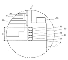
- FIG. 2 is an enlarged view of the tolerance and thermal deformation absorbing structure according to the embodiment of the present invention, indicated by B portion in FIG.
- the tolerance and thermal deformation absorption structure of the turbo molecular pump 1 according to the embodiment of the present invention includes a casing 2, a base 3, O-rings 81, 82, 83, spacers 90, 91. And a bolt 70.
- the tolerance and thermal deformation absorbing structure according to the present embodiment includes an O-ring (81, 82, 83) having a diameter of 5.33 mm and a plate-like spacer (90, 91) having a thickness of 6 mm. I have.
- a gap is provided between the casing 2 and the base 3, and O-rings (81, 82, 83) are arranged in the gap. Further, a spacer 90 and a spacer 91 are provided between the O-ring 81 and the O-ring 82 and between the O-ring 82 and the O-ring 83, respectively.
- the rounded O-rings (81, 82, 83) are arranged and sealed to each other, and there is a possibility that the intended sealing function cannot be fully achieved due to unstable contact between parts. Because there is a structure that sandwiches plate-shaped spacers (90, 91) between them, the structure that contacts the O-ring and the spacer instead of the O-rings stabilizes the contact between parts and improves the sealing function. This is to make it happen.
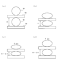
- FIGS. 3 (a) to 3 (d) show a stack of fixed wings 10 and O-rings (81, 82, 83) and spacers (90, 91) in the tolerance and thermal deformation absorbing structure according to the embodiment of the present invention.
- FIG. 4 is a conceptual diagram showing each state at various loads received from the fixed blade spacer 20. In FIG. 3, as an example, the O-rings 81 and 82 and the spacers 90 and 91 are extracted and described.
- FIG. 3A shows a state in which no load is applied to the O-rings (81, 82, 83) in the tolerance and thermal deformation absorbing structure according to the embodiment of the present invention. More specifically, before the casing 2 is covered in the assembly stage of the turbo molecular pump 1 according to the embodiment of the present invention, the O-rings (81, 82, 83) and the spacers (90, 91) are not loaded. The state under load is shown. In the present embodiment, the weights of the main bodies of the O-rings (81, 82, 83) and the main bodies of the spacers (90, 91) are not calculated as “loads” for convenience.
- FIG. 3B to 3D show a state in which the O-rings (81, 82, 83) are crushed due to the tolerance and thermal deformation absorbing structure according to the embodiment of the present invention. More specifically, FIG. 3B shows a state of the O-rings (81, 82, 83) having the design dimensions in the turbo molecular pump 1 according to the embodiment of the present invention. At this time, the collapse rate of the O-rings (81, 82, 83) is about 30%.
- FIG. 3C shows the tolerance and heat in the case where the height dimension due to the stacking of the fixed blade 10 and the fixed blade spacer 20 is minimized when the turbo molecular pump 1 according to the embodiment of the present invention is assembled.
- the state of the O-ring (81, 82, 83) disposed in the deformation absorbing structure is shown.
- the crushing rate of the O-rings (81, 82, 83) after the casing 2 and the base 3 are fastened with the bolt 70 becomes the maximum ( ⁇ : max). That is, since a large difference on the minus side occurs in the height dimension of the fixed blade 10 and the fixed blade spacer 20 stacked, the dimension C in FIG. 2 becomes smaller than the reference dimension, and as a result, the O-ring (81, The collapse rate of 82 and 83) is increased.
- FIG. 3D shows the tolerance and heat in the case where the height dimension due to the stacking of the fixed blade 10 and the fixed blade spacer 20 is maximized when the turbo molecular pump 1 according to the embodiment of the present invention is assembled.
- the state of the O-ring (81, 82, 83) disposed in the deformation absorbing structure is shown.
- the crushing rate of the O-rings (81, 82, 83) after the casing 2 and the base 3 are fastened with the bolt 70 is minimized ( ⁇ : min). That is, since a large plus difference is generated in the tolerance of stacking the fixed wing 10 and the fixed wing spacer 20, the dimension C in FIG. 2 becomes larger than the reference dimension, and as a result, the O-rings (81, 82, 83) the crushing rate is small.
- dH represents “the height fluctuation amount of the O-ring” and can be obtained by the following calculation formula (C).
- C)... DH (product variation + thermal deformation amount + component deformation amount) / N
- the height fluctuation amount (dH) of the O-ring (81, 82, 83) can be obtained only by the variation in the product of the fixed blade 10 or the fixed blade spacer 20.
- the tolerance and the thermal deformation absorbing structure according to the embodiment of the present invention can be calculated by using each component (the fixed wing 10 and the fixed wing spacer 20. Etc.) can be adapted to deformation due to thermal expansion.
- the limit crush rate ( ⁇ 1) of the O-ring which is a limit value at which the O-ring cracks or excessively deforms, is 40% as an example, and the crush rate required for the O-ring seal ( ⁇ 2) ) Is 20% as an example.
- the maximum collapse rate of the O-ring ( ⁇ : max) the limit collapse rate of the O-ring ( ⁇ 1), the minimum collapse rate of the O-ring ( ⁇ : min) and the O-ring seal
- D required crushing ratio
- an appropriate number of O-rings determined as described above are arranged in the gap between the casing 2 and the base 3 via a spacer, and then A plurality of O-rings (81, 82, 83) to be arranged can be configured to exhibit an appropriate repulsive force by fastening the gaps with bolts 70.
- the tolerance and thermal deformation absorbing structure in which the O-ring (81, 82, 83) is disposed can appropriately absorb the variation in the product of the fixed blade 10 or the fixed blade spacer 20 (tolerance absorption function). The difference in thermal expansion can be absorbed and the casing 2 and the base 3 can be properly sealed (surface sealing function).
- the collapse amount with respect to the diameter of the O-ring is expressed as a percentage, but the present invention is not limited to this.
- various representations (calculation methods) such as using an O-ring occupation amount with respect to the O-ring groove or using a contraction (compression) amount of the volume of the O-ring can be adopted.
- the number of O-rings arranged is three (three stages), but the number (number of stages) is not limited to this.
- Various combinations one, two, four, etc. may be considered depending on the clearance size for the tolerance and heat deformation absorbing structure and the type (performance) of the O-ring to be arranged.
- the fixed wing 10 uses a fixed wing having a large height dimensional tolerance (for example, a fixed wing formed by press molding), or is a full-stage wing type having a large number of stages of the fixed wing 10 and the fixed wing spacer 20.
- a large height dimensional tolerance for example, a fixed wing formed by press molding
- the O-ring to be disposed is multi-staged.
- the crushing margin of the O-ring per stage is configured to be less than the allowable strain.
- a spacer is provided between the O-rings arranged in multiple stages and the O-rings to prevent the O-rings from shifting.
- each component (the fixed blade 10 and the fixed blade spacer 20) has a small tolerance, and the fixed Even when the assembled dimensions of the blades 10 and the fixed blade spacers 20 are small, each component (the fixed blades 10 and the fixed blade spacers 20) has large tolerances. Even in the case where the dimension after the assembly of the stacked spacers 20 is large, the casing 2 and the base 3 are fastened with bolts 70 through the tolerance and heat deformation absorbing structure. The blade 10 and the fixed blade spacer 20 can be brought into close contact with each other without a gap. Therefore, the heat generated by the rotor blade 9 generated when the turbo molecular pump 1 operates can be efficiently radiated, and the risk of overheating of the turbo molecular pump 1 can be reduced.
- FIG. 4 is an enlarged view of a modified example of the tolerance and thermal deformation absorbing structure (B portion of FIG. 1) according to the above-described embodiment of the present invention.
- the tolerance and thermal deformation absorbing structure according to the present modification are similar to the embodiment shown in FIG. 2, the casing 2, the base 3, the O-rings 81, 82, 83, and the spacers. 90 and 91 and a bolt 70.
- a gap (gap) is provided in the base 3, and O-rings (81, 82, 83) are arranged in the gap, and the O-ring is arranged.
- a spacer 90 and a spacer 91 are provided between 81 and the O-ring 82 and between the O-ring 82 and the O-ring 83, respectively.
- a gap due to tolerance and a thermal deformation absorbing structure may be formed between the casing 2 and the base 3 as in the above-described embodiment of the present invention. Note that the above-described relational expressions and calculation formulas (A) to (E) are applied in the same way as the embodiment described with reference to FIGS.
- the casing 2 and the base 3 are face-sealed by the tolerance and the thermal deformation absorption structure provided between the casing 2 and the base 3. Therefore, the O-rings (81, 82, 83) disposed in the tolerance and thermal deformation absorbing structure are only loaded from above when assembling the turbo molecular pump 1, and force is applied in the shear direction to the side surface. Since it is not added, it is not necessary to apply vacuum grease for avoiding breakage due to the force in the shear direction.
- the turbo molecular pump 1 can assemble a vacuum pump without using vacuum grease, thereby avoiding the risk of vacuum contamination that can be expected when using vacuum grease. Is possible.
- the turbo molecular pump designed with a large dimensional tolerance of the fixed blade 10 and the fixed blade spacer 20 Appropriate tolerances and thermal deformation absorbing structures and face seal structures can be realized even for all-stage blade type turbo molecular pumps having a large number of stages.
- the present invention is not limited to this, and it varies depending on the diameter of the O-ring to be arranged and the size of the gap (gap) provided between the casing 2 and the base 3 (depth in the axial direction, width in the radial direction). It is possible to change the design. Alternatively, if appropriate stability can be maintained in the tolerance and thermal deformation absorption structure, a configuration in which only a plurality of O-rings are provided without providing a spacer between the O-rings and the O-rings is also possible. Is possible.
- a vacuum pump that can be assembled without using vacuum grease, and thus it is possible to avoid vacuum contamination due to vacuum grease.
- a vacuum pump is provided that can realize an appropriate tolerance, a thermal deformation absorbing structure, and a face seal structure even when the height dimensional tolerance of the fixed blade or the fixed blade spacer is increased. It becomes possible.
Landscapes
- Engineering & Computer Science (AREA)
- Mechanical Engineering (AREA)
- General Engineering & Computer Science (AREA)
- Non-Positive Displacement Air Blowers (AREA)
Abstract
La présente invention concerne une pompe à vide. Le but de la présente invention est de réaliser une pompe à vide qui peut être assemblée sans l'application d'une graisse à vide et qui peut assurer une étanchéité de surface appropriée. Une structure d'absorption des tolérances et de la déformation thermique, dans laquelle est disposée une bague torique qui est conçue pour être serrée avec un taux de serrage qui laisse intact le bon degré de force de répulsion, est placée entre un boîtier et une base. Dans la pompe à vide, lorsqu'on utilise des stators présentant une grande tolérance sur la hauteur (par exemple, des stators emboutis), ou lorsque la pompe à vide est une pompe tous niveaux possédant un grand nombre de niveaux de rotors et de stators, si le taux de serrage de la bague torique disposée dans la structure d'absorption des tolérances et de la déformation thermique dépasse la déformation admissible (distorsion) avec un seul niveau, les bagues toriques sont disposées à plusieurs niveaux et le taux d'écrasement de la bague torique par niveau est calculé de telle sorte que la bague d'étanchéité conserve une bonne étanchéité. Dans ce cas, des entretoises de forme annulaire sont placées entre les bagues toriques disposées à plusieurs niveaux pour empêcher les bagues toriques de s'écarter de la bonne position l'une par rapport à l'autre.
Priority Applications (1)
| Application Number | Priority Date | Filing Date | Title |
|---|---|---|---|
| JP2013517937A JP6113071B2 (ja) | 2011-06-03 | 2012-05-07 | 真空ポンプ |
Applications Claiming Priority (2)
| Application Number | Priority Date | Filing Date | Title |
|---|---|---|---|
| JP2011-125766 | 2011-06-03 | ||
| JP2011125766 | 2011-06-03 |
Publications (1)
| Publication Number | Publication Date |
|---|---|
| WO2012165105A1 true WO2012165105A1 (fr) | 2012-12-06 |
Family
ID=47258969
Family Applications (1)
| Application Number | Title | Priority Date | Filing Date |
|---|---|---|---|
| PCT/JP2012/061672 Ceased WO2012165105A1 (fr) | 2011-06-03 | 2012-05-07 | Pompe à vide |
Country Status (2)
| Country | Link |
|---|---|
| JP (1) | JP6113071B2 (fr) |
| WO (1) | WO2012165105A1 (fr) |
Cited By (4)
| Publication number | Priority date | Publication date | Assignee | Title |
|---|---|---|---|---|
| JP2016176340A (ja) * | 2015-03-18 | 2016-10-06 | 株式会社島津製作所 | ターボ分子ポンプ |
| GB2553323A (en) * | 2016-09-01 | 2018-03-07 | Edwards Ltd | Pump assemblies with sealing |
| CN108506225A (zh) * | 2017-02-27 | 2018-09-07 | 株式会社岛津制作所 | 电源一体型真空泵 |
| EP4379215A4 (fr) * | 2021-07-26 | 2025-07-02 | Edwards Japan Ltd | Pompe à vide |
Citations (4)
| Publication number | Priority date | Publication date | Assignee | Title |
|---|---|---|---|---|
| JP2001153087A (ja) * | 1999-10-28 | 2001-06-05 | Pfeiffer Vacuum Gmbh | ターボ分子ポンプ |
| JP2001271786A (ja) * | 2000-03-02 | 2001-10-05 | Pfeiffer Vacuum Gmbh | ターボ分子ポンプ |
| WO2010007975A1 (fr) * | 2008-07-14 | 2010-01-21 | エドワーズ株式会社 | Pompe à vide |
| WO2010016141A1 (fr) * | 2008-08-08 | 2010-02-11 | 株式会社島津製作所 | Pompe à vide rotative |
Family Cites Families (3)
| Publication number | Priority date | Publication date | Assignee | Title |
|---|---|---|---|---|
| US6508631B1 (en) * | 1999-11-18 | 2003-01-21 | Mks Instruments, Inc. | Radial flow turbomolecular vacuum pump |
| DE102007044945A1 (de) * | 2007-09-20 | 2009-04-09 | Pfeiffer Vacuum Gmbh | Vakuumpumpe |
| JP5115134B2 (ja) * | 2007-10-12 | 2013-01-09 | 株式会社島津製作所 | 真空ポンプ装置 |
-
2012
- 2012-05-07 WO PCT/JP2012/061672 patent/WO2012165105A1/fr not_active Ceased
- 2012-05-07 JP JP2013517937A patent/JP6113071B2/ja not_active Expired - Fee Related
Patent Citations (4)
| Publication number | Priority date | Publication date | Assignee | Title |
|---|---|---|---|---|
| JP2001153087A (ja) * | 1999-10-28 | 2001-06-05 | Pfeiffer Vacuum Gmbh | ターボ分子ポンプ |
| JP2001271786A (ja) * | 2000-03-02 | 2001-10-05 | Pfeiffer Vacuum Gmbh | ターボ分子ポンプ |
| WO2010007975A1 (fr) * | 2008-07-14 | 2010-01-21 | エドワーズ株式会社 | Pompe à vide |
| WO2010016141A1 (fr) * | 2008-08-08 | 2010-02-11 | 株式会社島津製作所 | Pompe à vide rotative |
Cited By (6)
| Publication number | Priority date | Publication date | Assignee | Title |
|---|---|---|---|---|
| JP2016176340A (ja) * | 2015-03-18 | 2016-10-06 | 株式会社島津製作所 | ターボ分子ポンプ |
| GB2553323A (en) * | 2016-09-01 | 2018-03-07 | Edwards Ltd | Pump assemblies with sealing |
| WO2018042150A1 (fr) * | 2016-09-01 | 2018-03-08 | Edwards Limited | Ensembles pompes à étanchéité |
| CN108506225A (zh) * | 2017-02-27 | 2018-09-07 | 株式会社岛津制作所 | 电源一体型真空泵 |
| CN108506225B (zh) * | 2017-02-27 | 2020-05-08 | 株式会社岛津制作所 | 电源一体型真空泵 |
| EP4379215A4 (fr) * | 2021-07-26 | 2025-07-02 | Edwards Japan Ltd | Pompe à vide |
Also Published As
| Publication number | Publication date |
|---|---|
| JP6113071B2 (ja) | 2017-04-12 |
| JPWO2012165105A1 (ja) | 2015-02-23 |
Similar Documents
| Publication | Publication Date | Title |
|---|---|---|
| JP3961273B2 (ja) | 真空ポンプ | |
| US6343910B1 (en) | Turbo-molecular pump | |
| EP2872744B1 (fr) | Rotor destiné à un compresseur radial et procédé de construction associé | |
| JP6113071B2 (ja) | 真空ポンプ | |
| US8109744B2 (en) | Turbo vacuum pump | |
| CN103827508B (zh) | 轴流式流体机械及其可变静叶片驱动装置 | |
| JP6154787B2 (ja) | 真空ポンプ | |
| JPWO2009063890A1 (ja) | 多段式ドライポンプ | |
| CN108105121B (zh) | 一种多级复合高真空干泵 | |
| US6409468B1 (en) | Turbo-molecular pump | |
| JP2010265895A (ja) | 真空ポンプ | |
| JP6133213B2 (ja) | 固定部材及び真空ポンプ | |
| KR20020061691A (ko) | 터보 압축기의 열손실 저감구조 | |
| KR102558618B1 (ko) | 가스를 압축 또는 팽창시키기 위한 요소 및 그러한 요소를 제어하기 위한 방법 | |
| JP7677352B2 (ja) | コンプレッサ駆動シャフトアセンブリ及びこれを含むコンプレッサ | |
| US20060280595A1 (en) | Stator disc for a turbomolecular pump | |
| JP2009092039A (ja) | 2段スクリュー式真空ポンプ | |
| JP2004278500A (ja) | 分子ポンプ | |
| CN112983850B (zh) | 一种三轮离心压缩机 | |
| EP1314893B1 (fr) | Pompe à vide | |
| CN113518864B (zh) | 真空泵及用于真空泵的密封部件 | |
| WO2016160472A1 (fr) | Ensemble de montage pour un faisceau d'un compresseur | |
| JP2009092041A (ja) | 片持ち式回転ポンプ | |
| WO2022184739A1 (fr) | Ensemble stator | |
| JPH0275796A (ja) | 複合真空ポンプ |
Legal Events
| Date | Code | Title | Description |
|---|---|---|---|
| 121 | Ep: the epo has been informed by wipo that ep was designated in this application |
Ref document number: 12793498 Country of ref document: EP Kind code of ref document: A1 |
|
| ENP | Entry into the national phase |
Ref document number: 2013517937 Country of ref document: JP Kind code of ref document: A |
|
| NENP | Non-entry into the national phase |
Ref country code: DE |
|
| 122 | Ep: pct application non-entry in european phase |
Ref document number: 12793498 Country of ref document: EP Kind code of ref document: A1 |