WO2012165153A1 - Système d'alimentation électrique - Google Patents
Système d'alimentation électrique Download PDFInfo
- Publication number
- WO2012165153A1 WO2012165153A1 PCT/JP2012/062607 JP2012062607W WO2012165153A1 WO 2012165153 A1 WO2012165153 A1 WO 2012165153A1 JP 2012062607 W JP2012062607 W JP 2012062607W WO 2012165153 A1 WO2012165153 A1 WO 2012165153A1
- Authority
- WO
- WIPO (PCT)
- Prior art keywords
- power
- algorithm
- storage battery
- commercial
- generated
- Prior art date
- Legal status (The legal status is an assumption and is not a legal conclusion. Google has not performed a legal analysis and makes no representation as to the accuracy of the status listed.)
- Ceased
Links
Images








Classifications
-
- G—PHYSICS
- G05—CONTROLLING; REGULATING
- G05F—SYSTEMS FOR REGULATING ELECTRIC OR MAGNETIC VARIABLES
- G05F1/00—Automatic systems in which deviations of an electric quantity from one or more predetermined values are detected at the output of the system and fed back to a device within the system to restore the detected quantity to its predetermined value or values, i.e. retroactive systems
- G05F1/66—Regulating electric power
-
- G—PHYSICS
- G06—COMPUTING OR CALCULATING; COUNTING
- G06Q—INFORMATION AND COMMUNICATION TECHNOLOGY [ICT] SPECIALLY ADAPTED FOR ADMINISTRATIVE, COMMERCIAL, FINANCIAL, MANAGERIAL OR SUPERVISORY PURPOSES; SYSTEMS OR METHODS SPECIALLY ADAPTED FOR ADMINISTRATIVE, COMMERCIAL, FINANCIAL, MANAGERIAL OR SUPERVISORY PURPOSES, NOT OTHERWISE PROVIDED FOR
- G06Q50/00—Information and communication technology [ICT] specially adapted for implementation of business processes of specific business sectors, e.g. utilities or tourism
- G06Q50/06—Energy or water supply
-
- H—ELECTRICITY
- H02—GENERATION; CONVERSION OR DISTRIBUTION OF ELECTRIC POWER
- H02J—ELECTRIC POWER NETWORKS; CIRCUIT ARRANGEMENTS OR SYSTEMS FOR SUPPLYING OR DISTRIBUTING ELECTRIC POWER; SYSTEMS FOR STORING ELECTRIC ENERGY
- H02J3/00—Circuit arrangements for AC mains or AC distribution networks
- H02J3/12—Arrangements for adjusting voltage in AC networks by changing a characteristic of the network load
- H02J3/14—Arrangements for adjusting voltage in AC networks by changing a characteristic of the network load by switching loads on to, or off from, the networks, e.g. progressively balanced loading
-
- H—ELECTRICITY
- H02—GENERATION; CONVERSION OR DISTRIBUTION OF ELECTRIC POWER
- H02J—ELECTRIC POWER NETWORKS; CIRCUIT ARRANGEMENTS OR SYSTEMS FOR SUPPLYING OR DISTRIBUTING ELECTRIC POWER; SYSTEMS FOR STORING ELECTRIC ENERGY
- H02J3/00—Circuit arrangements for AC mains or AC distribution networks
- H02J3/38—Arrangements for feeding a single network from two or more generators or sources in parallel; Arrangements for feeding already energised networks from additional generators or sources in parallel
- H02J3/381—Dispersed generators
-
- H—ELECTRICITY
- H02—GENERATION; CONVERSION OR DISTRIBUTION OF ELECTRIC POWER
- H02J—ELECTRIC POWER NETWORKS; CIRCUIT ARRANGEMENTS OR SYSTEMS FOR SUPPLYING OR DISTRIBUTING ELECTRIC POWER; SYSTEMS FOR STORING ELECTRIC ENERGY
- H02J3/00—Circuit arrangements for AC mains or AC distribution networks
- H02J3/38—Arrangements for feeding a single network from two or more generators or sources in parallel; Arrangements for feeding already energised networks from additional generators or sources in parallel
- H02J3/46—Controlling the sharing of generated power between the generators, sources or networks
-
- H—ELECTRICITY
- H02—GENERATION; CONVERSION OR DISTRIBUTION OF ELECTRIC POWER
- H02J—ELECTRIC POWER NETWORKS; CIRCUIT ARRANGEMENTS OR SYSTEMS FOR SUPPLYING OR DISTRIBUTING ELECTRIC POWER; SYSTEMS FOR STORING ELECTRIC ENERGY
- H02J7/00—Circuit arrangements for charging or discharging batteries or for supplying loads from batteries
- H02J7/34—Parallel operation in networks using both storage and other DC sources, e.g. providing buffering
- H02J7/35—Parallel operation in networks using both storage and other DC sources, e.g. providing buffering with light sensitive cells
-
- H—ELECTRICITY
- H02—GENERATION; CONVERSION OR DISTRIBUTION OF ELECTRIC POWER
- H02J—ELECTRIC POWER NETWORKS; CIRCUIT ARRANGEMENTS OR SYSTEMS FOR SUPPLYING OR DISTRIBUTING ELECTRIC POWER; SYSTEMS FOR STORING ELECTRIC ENERGY
- H02J2101/00—Supply or distribution of decentralised, dispersed or local electric power generation
- H02J2101/20—Dispersed power generation using renewable energy sources
- H02J2101/22—Solar energy
- H02J2101/24—Photovoltaics
-
- H—ELECTRICITY
- H02—GENERATION; CONVERSION OR DISTRIBUTION OF ELECTRIC POWER
- H02J—ELECTRIC POWER NETWORKS; CIRCUIT ARRANGEMENTS OR SYSTEMS FOR SUPPLYING OR DISTRIBUTING ELECTRIC POWER; SYSTEMS FOR STORING ELECTRIC ENERGY
- H02J2105/00—Networks for supplying or distributing electric power characterised by their spatial reach or by the load
- H02J2105/50—Networks for supplying or distributing electric power characterised by their spatial reach or by the load for selectively controlling the operation of the loads
- H02J2105/52—Networks for supplying or distributing electric power characterised by their spatial reach or by the load for selectively controlling the operation of the loads for limitation of the power consumption in the networks or in one section of the networks, e.g. load shedding or peak shaving
-
- Y—GENERAL TAGGING OF NEW TECHNOLOGICAL DEVELOPMENTS; GENERAL TAGGING OF CROSS-SECTIONAL TECHNOLOGIES SPANNING OVER SEVERAL SECTIONS OF THE IPC; TECHNICAL SUBJECTS COVERED BY FORMER USPC CROSS-REFERENCE ART COLLECTIONS [XRACs] AND DIGESTS
- Y02—TECHNOLOGIES OR APPLICATIONS FOR MITIGATION OR ADAPTATION AGAINST CLIMATE CHANGE
- Y02B—CLIMATE CHANGE MITIGATION TECHNOLOGIES RELATED TO BUILDINGS, e.g. HOUSING, HOUSE APPLIANCES OR RELATED END-USER APPLICATIONS
- Y02B70/00—Technologies for an efficient end-user side electric power management and consumption
- Y02B70/30—Systems integrating technologies related to power network operation and communication or information technologies for improving the carbon footprint of the management of residential or tertiary loads, i.e. smart grids as climate change mitigation technology in the buildings sector, including also the last stages of power distribution and the control, monitoring or operating management systems at local level
- Y02B70/3225—Demand response systems, e.g. load shedding, peak shaving
-
- Y—GENERAL TAGGING OF NEW TECHNOLOGICAL DEVELOPMENTS; GENERAL TAGGING OF CROSS-SECTIONAL TECHNOLOGIES SPANNING OVER SEVERAL SECTIONS OF THE IPC; TECHNICAL SUBJECTS COVERED BY FORMER USPC CROSS-REFERENCE ART COLLECTIONS [XRACs] AND DIGESTS
- Y02—TECHNOLOGIES OR APPLICATIONS FOR MITIGATION OR ADAPTATION AGAINST CLIMATE CHANGE
- Y02E—REDUCTION OF GREENHOUSE GAS [GHG] EMISSIONS, RELATED TO ENERGY GENERATION, TRANSMISSION OR DISTRIBUTION
- Y02E10/00—Energy generation through renewable energy sources
- Y02E10/50—Photovoltaic [PV] energy
- Y02E10/56—Power conversion systems, e.g. maximum power point trackers
-
- Y—GENERAL TAGGING OF NEW TECHNOLOGICAL DEVELOPMENTS; GENERAL TAGGING OF CROSS-SECTIONAL TECHNOLOGIES SPANNING OVER SEVERAL SECTIONS OF THE IPC; TECHNICAL SUBJECTS COVERED BY FORMER USPC CROSS-REFERENCE ART COLLECTIONS [XRACs] AND DIGESTS
- Y04—INFORMATION OR COMMUNICATION TECHNOLOGIES HAVING AN IMPACT ON OTHER TECHNOLOGY AREAS
- Y04S—SYSTEMS INTEGRATING TECHNOLOGIES RELATED TO POWER NETWORK OPERATION, COMMUNICATION OR INFORMATION TECHNOLOGIES FOR IMPROVING THE ELECTRICAL POWER GENERATION, TRANSMISSION, DISTRIBUTION, MANAGEMENT OR USAGE, i.e. SMART GRIDS
- Y04S20/00—Management or operation of end-user stationary applications or the last stages of power distribution; Controlling, monitoring or operating thereof
- Y04S20/20—End-user application control systems
- Y04S20/222—Demand response systems, e.g. load shedding, peak shaving
Definitions
- the present invention relates to a power supply system.
- a power supply system that combines power generated by a solar power generation device with a commercial power source and further stores the power in a storage battery to supply power from the commercial power source, the solar power generation, or the storage battery (for example, Japanese Patent Publication 2011). No.-15501).
- power companies divide the distribution area into multiple regions, create power supply schedules for each region in advance, and supply power to consumers Make the schedule known in advance. Then, for each region, the power supply capacity (power generation capacity) in the distribution area can be increased by combining the time period for supplying power from the commercial power system and the time period for stopping power supply from the commercial power system. To meet demand.
- an object of the present invention is to provide a power supply system capable of achieving both improvement of the power supply / demand balance in a commercial power system and securing of power at the time of a power failure in each consumer.
- the power supply system of the present invention is a power supply system that supplies power to devices using generated power of a distributed power source, stored power of a storage battery, and commercial power supplied from a commercial power system, and Supplying the generated power of the power source to the device, charging the storage battery with surplus power obtained by subtracting the used power of the device from the generated power of the distributed power source, and when there is no surplus power, the stored power of the storage battery is distributed to the device Supplying to the device together with the generated power of the power source, the insufficient power obtained by subtracting the generated power of the distributed power source and the power supplied by the storage battery from the power used by the device is a first algorithm supplied from the commercial power system, A surplus power mode in which the surplus power is reversely flowed to the commercial power system, the total amount of generated power of the distributed power source is reversely flowed to the commercial power system, and the storage battery Characterized in that it comprises a controller for executing second and algorithms switchably having modes peak assist mode for supplying DENDEN force to the device.
- the controller prohibits supplying the storage power of the storage battery to the device before a power failure of the commercial power system, and the electricity charge of the commercial power system before the power failure of the commercial power system is It is preferable to charge the storage battery to a predetermined storage amount using the commercial power during a relatively inexpensive time period and execute the first algorithm during a power failure.
- the controller executes the first algorithm when the power supply capacity from the commercial power system satisfies the power demand, and when the power supply capacity is insufficient with respect to the power demand, the second It is preferable to execute the algorithm.
- the controller switches to the peak assist mode in a time period in which the power supply capability is predicted to be insufficient with respect to the power demand during a period in which the second algorithm is executed.
- the controller receives data indicating whether or not the electric power company purchases surplus power in advance from the management server of the electric power company, and is determined that the surplus power is not purchased from the data. It is preferable to execute the first algorithm when it is determined that the second algorithm is executed when it is determined that the purchase of surplus power is performed.
- the controller receives from the management server data including a timing for starting a peak assist mode in a period in which the second algorithm is executed.
- the controller automatically executes the first algorithm when communication with the management server is interrupted or when a power failure occurs in a commercial power system.
- FIG. 3 is a pattern diagram showing a peak assist algorithm according to the first embodiment.
- FIG. 3 is a pattern diagram showing a peak assist algorithm according to the first embodiment.
- FIG. 3 is a pattern diagram showing a peak assist algorithm according to the first embodiment.
- FIG. 5 is a schematic diagram illustrating an operation of a peak assist algorithm according to the first embodiment.
- FIG. 5 is a schematic diagram illustrating an operation of a peak assist algorithm according to the first embodiment.
- FIG. 5 is a schematic diagram illustrating an operation of a peak assist algorithm according to the first embodiment.
- FIG. 5 is a schematic diagram illustrating an operation of a peak assist algorithm according to the first embodiment.
- FIG. 5 is a schematic diagram illustrating an operation of a peak assist algorithm according to the first embodiment.
- FIG. 5 is a schematic diagram illustrating an operation of a peak assist algorithm according to the first embodiment.
- FIG. 5 is a schematic diagram illustrating an operation of a peak assist algorithm according to the first embodiment.
- FIG. 6 is a pattern diagram showing the operation of the second embodiment.
- FIG. 6 is a pattern diagram showing the operation of the second embodiment.
- FIG. 6 is a pattern diagram showing the operation of the second embodiment.
- FIG. 10 is a pattern diagram showing another operation of the second embodiment.
- FIG. 10 is a pattern diagram showing another operation of the second embodiment.
- FIG. 10 is a pattern diagram showing another operation of the second embodiment.
- the power supply system of the present embodiment has the configuration shown in FIG. 1 and is used in each consumer who is supplied with power from an electric power company.
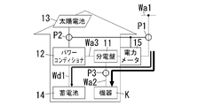
- This system includes a distribution board 11, a power conditioner 12, a solar battery 13, a storage battery 14, a power meter 15, and a controller 16 as main components.
- the pole transformer Tr provided around each customer converts the 6600V system sent from the power company's substation PS via the high-voltage distribution line Wa0 into a 200V / 100V system, and a single-phase three-wire system 200V. Supplied to / 100V main line Wa1.
- the main electric line Wa ⁇ b> 1 is drawn into a consumer such as each dwelling unit, detached house, factory, office, etc. of the apartment house and connected to the distribution board 11.
- the trunk line electric circuit Wa1 and the high voltage distribution line Wa0 correspond to the commercial power system of the present invention.
- a main power breaker, a branch breaker, a solar power breaker, and the like are accommodated, and the main line Wa1 branches to a plurality of branch lines Wa2 via the main power breaker and the branch breaker.
- Each branch electric circuit Wa ⁇ b> 2 is connected to a device K such as a lighting device, an air conditioner, or a home appliance, and supplies AC power to these devices K.
- a device K such as a lighting device, an air conditioner, or a home appliance, and supplies AC power to these devices K.
- FIG. 1 only one branch electric circuit Wa2 is shown.
- the power conditioner 12 constitutes a solar power generation device by being combined with the solar cell 13, and further constitutes a power storage device by being combined with the storage battery 14.
- the power conditioner 12 has a grid-connected operation function in which the AC output is coordinated with commercial power supplied by the substation PS.
- the power conditioner 12 is connected to the main line Wa1 from the AC circuit Wa3 via the distribution board 11, and the AC output is supplied to the branch circuit Wa2 via the distribution board 11, or the commercial power system Reverse power flow (electric power sales).
- the storage battery 14 is comprised by secondary batteries, such as a lithium ion battery, for example, and is connected to the power conditioner 12 via the charging / discharging path Wd1, and charging / discharging control is made by the power conditioner 12.
- the power conditioner 12 charges the storage battery 14 using the commercial power from the commercial power system and the generated power of the solar battery 13. Further, the power conditioner 12 converts the stored power of the storage battery 14 into alternating current, and supplies the alternating current from the alternating current circuit Wa3 to the branch circuit Wa2.
- the power meter 15 measures the power transferred between the commercial power system and the customer at the system monitoring point P1 of the main line Wa1, and at the power generation amount monitoring point P2 of the output of the solar cell 13, the power meter 15 The generated power is measured, and the measurement result is transmitted to the controller 16. Moreover, the measurement result of the electric power meter 15 is transmitted to the management server CS of the electric power company via the Internet NT1, and the electric power company uses it as meter-reading data of the amount of power purchased and the amount of electric power sold at each consumer.
- the communication between the power meter 15 and the controller 16 may be either wireless communication or wired communication.
- the controller 16 measures the load power supplied from the distribution board 11 to the device K at the load monitoring point P3 of the branch circuit Wa2. Then, the controller 16 performs charge / discharge control of the storage battery 14 by the power conditioner 12 based on the measurement result at the load monitoring point P3, the measurement result by the power meter 15, the storage amount of the storage battery 14, and the like. Further, the controller 16 of each customer is connected to the management server CS so as to be able to communicate via the Internet NT1.
- the controller 16 of this system uses the “local production for local consumption algorithm” and the “peak assist algorithm” in order to achieve both the improvement of the power supply / demand balance in the commercial power system and the securing of power at the time of power outage for each consumer.
- Two algorithms are executed in a switchable manner.
- the local production for local consumption algorithm corresponds to the first algorithm of the present invention
- the peak assist algorithm corresponds to the second algorithm of the present invention.
- the power company determines whether or not the power generation capacity of the power station satisfies the power demand on the next day based on the power generation capacity of the power station (power supply capacity from the commercial power system) and the prediction of power demand. Then, based on this determination result, the next day's power selling system is set to “no purchase system” or “surplus power selling system”, and the setting of this power selling system is notified to each consumer.
- the management server CS determines the power sale system of the next day to the controller 16 of each consumer as a “no purchase system”. ”Is set.
- the no purchase system is a system in which the electric power company does not purchase the power generated by the solar battery 13. That is, the management server CS of the power company transmits data indicating whether or not to purchase surplus power the next day to the controller 16 of each customer via the Internet NT1.
- the controller 16 sets the next day operation to “local production for local consumption algorithm (first algorithm)”, and the power conditioner according to the local production for local consumption algorithm. 12 performs charge / discharge control of the storage battery 14.
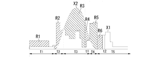
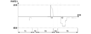
- 2A to 2C show the daily operation pattern in which the local production for local consumption algorithm is executed.
- FIG. 2A shows a daily power pattern, where X1 is the amount of power used in the consumer, and X2 is the amount of power generated by the solar cell 13.
- FIG. 2B shows a storage amount pattern of the storage battery 14, and
- FIG. 2C shows a power pattern at the system monitoring point P1.
- 3A to 3D show a schematic operation in each time zone of the local production for local consumption algorithm.
- non-purchase system is a normal power selling system
- local production for local consumption algorithm is an algorithm that is normally executed.
- the power storage operation of FIG. 3A is performed, and the controller 16 uses the midnight power to move the storage battery 14 to the target power storage amount M1.
- the power conditioner 12 is instructed to charge.
- a region R1 in FIG. 2A indicates the amount of power stored by the midnight power.
- the device K is operating using midnight power supplied from the substation PS. Therefore, due to the storage of the storage battery 14 and the operation of the device K, tide current is generated at the system monitoring point P1 at night T1.
- the controller 16 covers the insufficient power using the stored power of the storage battery 14, so the discharge operation of FIG.
- the power conditioner 12 is instructed to Region R2 in FIG. 2A indicates the insufficient power covered by this stored power.
- the power conditioner 12 carries out discharge control of the storage battery 14 so that the tide power in the system
- the generated power of the solar cell 13 is also converted into alternating current by the power conditioner 12 and supplied to the branch electric circuit Wa2. That is, the device K operates with the generated power of the solar battery 13 and the stored power of the storage battery 14.
- zone T3 (daytime) when the electric power generation amount X2 of the solar cell 13 is larger than the electric power consumption amount X1 in a consumer, the controller 16 stores the surplus electric power of solar power generation in the storage battery 14, Therefore FIG.
- the power conditioner 12 is instructed to Region R3 in FIG. 2A shows the amount of power stored by this surplus power. And the power conditioner 12 charges the storage battery 14 using the generated electric power of the solar cell 13 so that the reverse power flow direction power at the system monitoring point P1 becomes zero. Moreover, the electric power generated by the solar cell 13 is converted into alternating current by the power conditioner 12 and is also supplied to the branch electric circuit Wa2. That is, the device K operates only with the power generated by the solar cell 13.
- the controller 16 causes the power conditioner 12 to stop the charging operation of the storage battery 14. Instruct. Surplus power of solar power generation that is no longer used for charging the storage battery 14 is sold. At this time, reverse power flow direction power is generated at the system monitoring point P1 for the operation of selling power. Region R4 in FIG. 2A shows the amount of power sold by this surplus power.
- the controller 16 covers the insufficient power using the stored power of the storage battery 14, and therefore the discharge operation of FIG.
- the power conditioner 12 is instructed to Region R5 in FIG. 2A indicates the insufficient power covered by this stored power.
- the power conditioner 12 carries out discharge control of the storage battery 14 so that the tide power in the system
- the controller 16 instructs the power conditioner 12 to perform a discharging operation in order to cover the insufficient power using the stored power of the storage battery 14.
- Region R6 in FIG. 2A indicates the insufficient power covered by this stored power.
- the power conditioner 12 carries out discharge control of the storage battery 14 so that the tide power in the system
- the controller 16 instructs the power conditioner 12 to stop the discharge operation of the storage battery 14. Thereafter, as shown in FIG. 3D, commercial power from the substation PS is supplied to the device K. That is, the device K operates using only commercial power supplied from the substation PS, and forward power is generated at the system monitoring point P1.
- the generated power of the solar cell 13 is stored in the storage battery 14 as much as possible, and the generated power and the stored power are controlled to be consumed in each consumer. Therefore, even at the time of a sudden power failure, each consumer can secure the power supply at the time of the power failure by the generated power of the solar cell 13 or the stored power of the storage battery 14.
- the management server CS changes the power sale system on the next day to the “surplus power power sale system” for the controller 16 of each consumer. Notify setting.
- the surplus power sales system is basically a system for selling the remainder (surplus power) of the power used by each consumer out of the power generated by the solar cell 13.
- the controller 16 sets the operation of the next day to “peak assist algorithm (second algorithm)” when the next day power selling system is set to “surplus power selling system”, and the power conditioner according to the peak assist algorithm. 12 performs charge / discharge control of the storage battery 14.
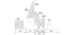
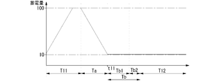
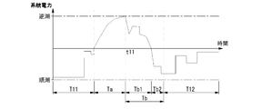
- 4A to 4C show the daily operation pattern in which the peak assist algorithm is executed.
- FIG. 4A shows a daily power pattern, where X11 is the amount of power used in the consumer and X12 is the amount of power generated by the solar cell 13.
- FIG. 4B shows a storage amount pattern of the storage battery 14, and
- FIG. 4C shows a power pattern at the system monitoring point P1.
- 5A to 5E show a schematic operation in each time zone of the peak assist algorithm.
- the storage operation of FIG. 5A is performed, and the controller 16 uses the midnight power to set the storage battery 14 to a target storage amount of 100%. Instruct the power conditioner 12 to charge up to A region R11 in FIG. 4A indicates the amount of power stored by the midnight power.
- the device K is operating using midnight power supplied from the substation PS. Therefore, due to the storage of the storage battery 14 and the operation of the device K, tide current is generated at the system monitoring point P1 at night T11.
- the “peak assist algorithm (second algorithm)” in this system has two operation modes of “surplus power selling mode” and “peak assist mode”. And in the daytime when the solar cell 13 generates power, it operates in the “surplus power sale mode” or “peak assist mode”, and the surplus power sale mode becomes the basic operation mode. Then, when notifying the controller 16 that the “surplus power selling system” is set, the management server CS also notifies the timing for starting the peak assist mode.
- peak assist mode setting period Ta it is predicted that the power generation capacity of the power plant will be insufficient with respect to the electric power demand during the period in which the peak assist algorithm is executed. It is set to the time zone when peak assist by electricity is expected.
- the peak assist mode period Ta starts at the timing when the solar cell 13 starts power generation.
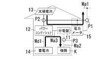
- the controller 16 instructs the power conditioner 12 to discharge the same amount of power as the load power at the load monitoring point P3 from the storage battery 14, and performs the discharging operation of FIG. 5B. . That is, the device K operates only with the stored power of the storage battery 14. Therefore, in the peak assist mode period Ta, the entire amount of power generated by the solar cell 13 is sold. At this time, reverse power flow direction power is generated at the system monitoring point P1 for the power selling operation. Region R12 in FIG. 4A shows the amount of power sold by this surplus power.
- the commercial power system includes solar power at each consumer.
- the total amount of power generated by the battery 13 flows backward. Therefore, since the amount of power supply from the commercial power system increases, the power supply / demand balance is improved so that the power supply from the commercial power system satisfies the power demand of the commercial power system.
- the controller 16 performs the discharging operation of the storage battery 14 so that the reverse power flow direction power at the system monitoring point P1 and the generated power of the solar cell 13 at the power generation amount monitoring point P2 coincide.
- the power conditioner 12 may be instructed to do so. Also in this case, the operation of FIG. 5B is performed.
- the controller 16 instructs the power conditioner 12 to stop the discharging operation of the storage battery 14, and sets the surplus power sale mode setting period (the surplus The process proceeds to the power sale mode period Tb).
- the surplus power sales mode period Tb the surplus power sales mode period Tb1 (daytime) in which the power generation amount X12 of the solar cell 13 is larger than the power consumption amount X11 in the consumer, and the power generation amount X12 of the solar cell 13 is the power consumption amount in the consumer. It is composed of a surplus power sale mode period Tb2 (evening) smaller than X11.
- the controller 16 instructs the power conditioner 12 to stop the charge / discharge operation of the storage battery 14.
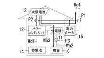
- the electric power generation amount X12 of the solar cell 13 is larger than the electric power consumption amount X11 in the consumer, as shown in FIG. 5C, the device K operates only with the electric power generated by the solar cell 13 and is not used by the device K. Surplus electricity from solar power generation is sold. At this time, reverse power flow direction power is generated at the system monitoring point P1 for the power selling operation. Region R13 in FIG. 4A shows the amount of power sold by this surplus power.
- the controller 16 instructs the power conditioner 12 to stop the charge / discharge operation of the storage battery 14.
- the apparatus K is the electric power generated by the solar cell 13 and the commercial electric power supplied from the substation PS. In operation, power in the tide direction is generated at the grid monitoring point P1. Region R14 in FIG. 4A indicates the insufficient power covered by this commercial power.
- the controller 16 instructs the power conditioner 12 to stop the charging / discharging operation of the storage battery 14. And since the electric power generation amount X12 of the solar cell 13 is zero, the apparatus K operate
- the peak assist mode period Ta is set at any time in a time period in which the power generation capacity of the power plant is predicted to be insufficient with respect to the power demand during the period of executing the peak assist algorithm. It does not always start at the morning timing.
- the controller 16 uses the stored power of the storage battery 14 to cover the insufficient power.
- the power conditioner 12 is instructed to perform a discharging operation.
- the power conditioner 12 carries out discharge control of the storage battery 14 so that the tide power in the system
- the generated power of the solar cell 13 is also converted into alternating current by the power conditioner 12 and supplied to the branch circuit Wa2. That is, the device K operates with the generated power of the solar battery 13 and the stored power of the storage battery 14.
- the present system switches between the two algorithms “local production for local consumption” and “peak assist algorithm” based on the prediction information of the power generation capacity and power demand of the power plant.
- the prediction information of the power generation capacity and power demand of the power plant is transmitted as data from the management server CS of the electric company via the Internet NT1, and based on the data
- the controller 16 switches between the two algorithms and executes them.
- the present invention is not limited to this, and such prediction information may be input directly by each consumer via an operation unit (not shown) provided in the controller 16, for example, offline.
- the local production / local consumption algorithm is executed, the generated power of the solar cell 13 is stored in the storage battery 14 as much as possible, and the generated power and the stored power are controlled to be consumed in each consumer. Therefore, even at the time of a sudden power failure, each consumer can secure the power supply at the time of the power failure by the generated power of the solar cell 13 or the stored power of the storage battery 14.
- the power generation capacity of the power plant is insufficient for the power demand, it is better to sell the generated power of the solar cell 13 as much as possible by executing the peak assist algorithm rather than the local production for local consumption algorithm.
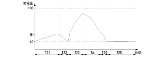
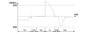
- FIGS. 6A to 6C show a daily operation pattern when it is determined that the power generation capacity of the power plant is insufficient with respect to the power demand around noon, and the local production / local consumption algorithm is switched to the peak assist algorithm.
- FIG. 6A shows a daily power pattern, where X21 is the amount of power used in the consumer, and X22 is the amount of power generated by the solar cell 13.
- FIG. 6B shows a storage amount pattern of the storage battery 14, and
- FIG. 6C shows a power pattern at the system monitoring point P1.
- this system operates with the local production for local consumption algorithm. Then, at night T21 where the unit price of commercial power (midnight power) supplied from the substation PS is low, the power storage operation of FIG. 3A is performed, and the controller 16 uses the midnight power to move the storage battery 14 to the target power storage amount M1. The power conditioner 12 is instructed to charge. A region R21 in FIG. 6A indicates the amount of power stored by the midnight power. In addition, the device K is operating using midnight power supplied from the substation PS. Therefore, due to the storage of the storage battery 14 and the operation of the device K, tide power is generated at the system monitoring point P1 at night T21.
- the controller 16 covers the insufficient power using the stored power of the storage battery 14, so the discharge operation of FIG.
- the power conditioner 12 is instructed to A region R22 in FIG. 6A indicates the insufficient power covered by the stored power.
- the power conditioner 12 carries out discharge control of the storage battery 14 so that the tide power in the system
- the controller 16 stores the surplus power of solar power generation in the storage battery 14, and therefore the charging operation of FIG.
- the power conditioner 12 is instructed to Region R23 in FIG. 6A shows the amount of power stored by this surplus power.
- the power conditioner 12 charges the storage battery 14 using the generated electric power of the solar cell 13 so that the reverse power flow direction power at the system monitoring point P1 becomes zero.
- the electric power generated by the solar cell 13 is converted into alternating current by the power conditioner 12 and is also supplied to the branch electric circuit Wa2. That is, the device K operates only with the power generated by the solar cell 13.
- the peak assist mode period Ta starts.
- the controller 16 instructs the power conditioner 12 to discharge the same amount of power as the load power at the load monitoring point P3 from the storage battery 14, and performs the discharging operation of FIG. 5B. That is, the device K operates only with the stored power of the storage battery 14. Therefore, in the peak assist mode period Ta, the entire amount of power generated by the solar cell 13 is sold. At this time, reverse power flow direction power is generated at the system monitoring point P1 for the power selling operation. Region R24 in FIG. 6A shows the amount of power sold by this surplus power.
- the controller 16 covers the power conditioner 12 to perform a discharging operation in order to cover the insufficient power using the stored power of the storage battery 14 in the subsequent time zone T24.
- Region R25 in FIG. 6A indicates the insufficient power covered by this stored power.
- the power conditioner 12 carries out discharge control of the storage battery 14 so that the tide power in the system
- the controller 16 instructs the power conditioner 12 to stop the discharging operation of the storage battery 14.
- the commercial power from the substation PS is supplied to the device K. That is, the device K operates using only commercial power supplied from the substation PS, and forward power is generated at the system monitoring point P1.
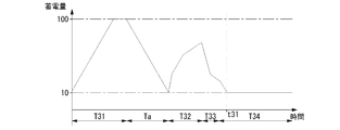
- FIGS. 7A to 7C show the daily operation pattern when the power generation capacity of the power plant is judged to be excessively supplied with respect to the power demand at around noon and the peak assist algorithm is switched to the local production for local consumption algorithm.
- FIG. 7A shows a daily power pattern, where X31 is the amount of power used in the consumer, and X32 is the amount of power generated by the solar cell 13.
- FIG. 7B shows a storage amount pattern of the storage battery 14, and
- FIG. 7C shows a power pattern at the system monitoring point P1.
- this system is operating with the peak assist algorithm. Then, at night T31 where the unit price of commercial power (midnight power) supplied from the substation PS is low, the power storage operation of FIG. 5A is performed, and the controller 16 uses the midnight power to set the storage battery 14 to the target storage amount 100%. Instruct the power conditioner 12 to charge up to A region R31 in FIG. 7A indicates the amount of power stored by the midnight power. In addition, the device K is operating using midnight power supplied from the substation PS. Therefore, due to the storage of the storage battery 14 and the operation of the device K, tide current is generated at the system monitoring point P1 at night T11.
- the peak assist mode period Ta is started at the timing when the solar cell 13 starts power generation.
- the controller 16 instructs the power conditioner 12 to discharge the same amount of power as the load power at the load monitoring point P3 from the storage battery 14, and performs the discharging operation of FIG. 5B. That is, the device K operates only with the stored power of the storage battery 14. Therefore, in the peak assist mode period Ta, the entire amount of power generated by the solar cell 13 is sold. At this time, reverse power flow direction power is generated at the system monitoring point P1 for the power selling operation. A region R32 in FIG. 7A indicates the amount of power sold by this surplus power.
- the controller 16 instructs the power conditioner 12 to perform the charging operation of FIG. 3C in order to store the surplus power of the photovoltaic power generation in the storage battery 14.
- a region R33 in FIG. 7A indicates the amount of power stored by this surplus power.
- the power conditioner 12 charges the storage battery 14 using the generated electric power of the solar cell 13 so that the reverse power flow direction power at the system monitoring point P1 becomes zero.
- the electric power generated by the solar cell 13 is converted into alternating current by the power conditioner 12 and is also supplied to the branch electric circuit Wa2. That is, the device K operates only with the power generated by the solar cell 13.
- the controller 16 covers the insufficient power using the stored power of the storage battery 14, and therefore the discharge operation of FIG.
- the power conditioner 12 is instructed to A region R34 in FIG. 7A indicates the power shortage covered by the stored power.
- the power conditioner 12 carries out discharge control of the storage battery 14 so that the tide power in the system
- the controller 16 instructs the power conditioner 12 to perform the discharging operation in order to cover the insufficient power using the stored power of the storage battery 14.
- a region R35 in FIG. 7A indicates the insufficient power covered by the stored power.
- the power conditioner 12 carries out discharge control of the storage battery 14 so that the tide power in the system
- the controller 16 instructs the power conditioner 12 to stop the discharge operation of the storage battery 14. Thereafter, as shown in FIG. 3D, commercial power from the substation PS is supplied to the device K. That is, the device K operates using only commercial power supplied from the substation PS, and forward power is generated at the system monitoring point P1.
- two algorithms “local production for local consumption algorithm” and “peak assist algorithm”, are used by switching based on the prediction information of the power generation capacity and power demand of the power plant.
- the target storage amount is determined based on the integrated value of the power used by the device K that operates using the stored power.
- the target power storage amount may be determined based on the history of the actual power consumption of the device K stored in advance.
- the management server CS notifies each customer's controller 16 of the power failure time zone.
- the controller 16 notified of the power failure time zone prohibits the discharge control before the power failure time zone, and charges the storage battery 14 to 100% of the charged amount using the midnight power by the power failure time zone (full charge).
- the local production for local consumption algorithm is executed during the power outage. Thus, each consumer can more reliably secure power during a power outage.
- controller 16 automatically executes a local production / local consumption algorithm when communication with the management server CS is interrupted or when a power failure occurs in the commercial power system.
- controller 16 may automatically execute the peak assist mode period Ta of the peak assist algorithm for a predetermined time (for example, 11:00 to 16:00) in a predetermined period (for example, summer).
- the controller 16 may automatically execute the peak assist algorithm by determining that the commercial power supply capability is insufficient.
- the solar cell 13 is used as the distributed power source, but other distributed power sources such as a fuel cell and a wind power generator may be used.
Landscapes
- Engineering & Computer Science (AREA)
- Power Engineering (AREA)
- Business, Economics & Management (AREA)
- Physics & Mathematics (AREA)
- General Physics & Mathematics (AREA)
- Health & Medical Sciences (AREA)
- Economics (AREA)
- Electromagnetism (AREA)
- Radar, Positioning & Navigation (AREA)
- Automation & Control Theory (AREA)
- Public Health (AREA)
- Water Supply & Treatment (AREA)
- General Health & Medical Sciences (AREA)
- Human Resources & Organizations (AREA)
- Marketing (AREA)
- Primary Health Care (AREA)
- Strategic Management (AREA)
- Tourism & Hospitality (AREA)
- General Business, Economics & Management (AREA)
- Theoretical Computer Science (AREA)
- Supply And Distribution Of Alternating Current (AREA)
- Management, Administration, Business Operations System, And Electronic Commerce (AREA)
- Charge And Discharge Circuits For Batteries Or The Like (AREA)
Abstract
L'invention concerne un dispositif de commande qui fournit un courant produit par une cellule solaire à un dispositif, qui charge une cellule de stockage avec le surplus de courant obtenu en soustrayant le courant utilisé par le dispositif du courant produit par la cellule solaire, qui fournit le courant stocké provenant de la cellule de stockage vers le dispositif lorsqu'il n'y a pas de surplus de courant, et qui exécute sélectivement : un algorithme de production locale pour consommation locale dans lequel un déficit de courant, qui est obtenu en soustrayant le courant produit par la cellule solaire et le courant fourni par la cellule de stockage du courant utilisé par le dispositif, est fourni par un système électrique commercial ; et un algorithme d'assistance de crête ayant un mode de vente du surplus de courant qui permet au surplus de courant de remonter vers le système électrique commercial et un mode d'assistance de crête qui permet que le courant produit par la cellule solaire remonte vers le système électrique commercial et qui fournit au dispositif le courant stocké provenant de la cellule de stockage.
Priority Applications (3)
| Application Number | Priority Date | Filing Date | Title |
|---|---|---|---|
| EP12792979.2A EP2701266A4 (fr) | 2011-05-30 | 2012-05-17 | Système d'alimentation électrique |
| CN201280023072.7A CN103518301A (zh) | 2011-05-30 | 2012-05-17 | 电力供给系统 |
| US14/061,883 US9523991B2 (en) | 2011-05-30 | 2013-10-24 | Power supply system |
Applications Claiming Priority (3)
| Application Number | Priority Date | Filing Date | Title |
|---|---|---|---|
| JP2011-120953 | 2011-05-30 | ||
| JP2011120953A JP2012249476A (ja) | 2011-05-30 | 2011-05-30 | 電力供給システム |
| JP2015148999A JP6202403B2 (ja) | 2011-05-30 | 2015-07-28 | 電力供給システム |
Related Child Applications (1)
| Application Number | Title | Priority Date | Filing Date |
|---|---|---|---|
| US14/061,883 Continuation US9523991B2 (en) | 2011-05-30 | 2013-10-24 | Power supply system |
Publications (1)
| Publication Number | Publication Date |
|---|---|
| WO2012165153A1 true WO2012165153A1 (fr) | 2012-12-06 |
Family
ID=59562616
Family Applications (1)
| Application Number | Title | Priority Date | Filing Date |
|---|---|---|---|
| PCT/JP2012/062607 Ceased WO2012165153A1 (fr) | 2011-05-30 | 2012-05-17 | Système d'alimentation électrique |
Country Status (5)
| Country | Link |
|---|---|
| US (1) | US9523991B2 (fr) |
| EP (1) | EP2701266A4 (fr) |
| JP (2) | JP2012249476A (fr) |
| CN (1) | CN103518301A (fr) |
| WO (1) | WO2012165153A1 (fr) |
Cited By (5)
| Publication number | Priority date | Publication date | Assignee | Title |
|---|---|---|---|---|
| EP2889981A3 (fr) * | 2013-11-04 | 2015-08-12 | Kiwigrid GmbH | Procédé de commande d'une distribution d'énergie |
| CN105005877A (zh) * | 2015-08-12 | 2015-10-28 | 上海申瑞继保电气有限公司 | 用户端能源管理系统负荷预警方法 |
| EP3021445A4 (fr) * | 2013-07-12 | 2016-07-13 | Panasonic Corp | Dispositif de gestion d'énergie, système de gestion d'énergie, serveur, procédé de gestion d'énergie, et programme |
| EP3054410A4 (fr) * | 2013-09-30 | 2016-11-02 | Panasonic Ip Man Co Ltd | Dispositif de gestion d'énergie, procédé de gestion d'énergie et programme |
| EP3098928A4 (fr) * | 2014-01-22 | 2017-06-21 | Kyocera Corporation | Système de régulation de l'énergie et procédé permettant de commander un système de régulation de l'énergie |
Families Citing this family (56)
| Publication number | Priority date | Publication date | Assignee | Title |
|---|---|---|---|---|
| US8849469B2 (en) | 2010-10-28 | 2014-09-30 | Microsoft Corporation | Data center system that accommodates episodic computation |
| US8810202B2 (en) * | 2011-07-15 | 2014-08-19 | Nec Corporation | Battery system and its control method |
| US9003216B2 (en) | 2011-10-03 | 2015-04-07 | Microsoft Technology Licensing, Llc | Power regulation of power grid via datacenter |
| JP5967516B2 (ja) | 2011-11-22 | 2016-08-10 | パナソニックIpマネジメント株式会社 | 電力管理装置、電力管理プログラム、及び、電力分配システム |
| JP5980575B2 (ja) * | 2012-05-29 | 2016-08-31 | 京セラ株式会社 | 電力システム、制御装置、及び制御方法 |
| JP6188350B2 (ja) * | 2013-03-01 | 2017-08-30 | 大和ハウス工業株式会社 | 電力供給システム |
| US9893530B2 (en) * | 2013-05-27 | 2018-02-13 | Kyocera Corporation | Power control device, power control method, and power control system |
| DE102014003054B4 (de) * | 2013-07-09 | 2022-03-17 | Sew-Eurodrive Gmbh & Co Kg | Verfahren zur Leistungsregelung eines Systems und Vorrichtung zur Leistungsregelung eines Systems |
| JP6184888B2 (ja) * | 2014-02-27 | 2017-08-23 | 東芝燃料電池システム株式会社 | コージェネレーションユニットを備えたコージェネレーションシステム |
| WO2015159388A1 (fr) * | 2014-04-16 | 2015-10-22 | 三菱電機株式会社 | Appareil de commande, système de commande, procédé de commande et programme |
| JP6235408B2 (ja) * | 2014-05-13 | 2017-11-22 | 株式会社 日立産業制御ソリューションズ | 発電システム、計画装置、および制御方法 |
| GB2528835A (en) * | 2014-06-25 | 2016-02-10 | Networked Electricity Storage Technology Ltd | Power control |
| WO2015199265A1 (fr) * | 2014-06-27 | 2015-12-30 | 이노넷 주식회사 | Dispositif de gestion de facteur de charge basé sur une réponse à la demande et procédé de gestion de facteur de charge |
| US20160087442A1 (en) | 2014-07-04 | 2016-03-24 | Stefan Matan | Modular power grid |
| US10879695B2 (en) | 2014-07-04 | 2020-12-29 | Apparent Labs, LLC | Grid network gateway aggregation |
| US11063431B2 (en) | 2014-07-04 | 2021-07-13 | Apparent Labs Llc | Hierarchical and distributed power grid control |
| US10234835B2 (en) | 2014-07-11 | 2019-03-19 | Microsoft Technology Licensing, Llc | Management of computing devices using modulated electricity |
| US9933804B2 (en) | 2014-07-11 | 2018-04-03 | Microsoft Technology Licensing, Llc | Server installation as a grid condition sensor |
| US20160011617A1 (en) * | 2014-07-11 | 2016-01-14 | Microsoft Technology Licensing, Llc | Power management of server installations |
| JP6453585B2 (ja) * | 2014-08-25 | 2019-01-16 | 京セラ株式会社 | 電力制御装置、蓄電装置、電力制御システム及び電力制御方法 |
| JP6372690B2 (ja) * | 2014-09-08 | 2018-08-15 | 清水建設株式会社 | 電力管理システム及び電力管理方法 |
| EP2998802B1 (fr) * | 2014-09-22 | 2019-04-03 | LEVION Technologies GmbH | Système de distribution d'énergie pour un réseau d'énergie |
| AU2015234308A1 (en) * | 2014-10-01 | 2016-04-21 | Embertec Pty Ltd | Power allocation system |
| EP3289655B1 (fr) * | 2015-04-28 | 2019-04-10 | RVE.SOL - Soluçoes de Energia Rural Lda. | Récipient de services autonomes |
| WO2016181617A1 (fr) | 2015-05-13 | 2016-11-17 | パナソニックIpマネジメント株式会社 | Dispositif de commande de charge/décharge |
| JP6454929B2 (ja) * | 2015-07-13 | 2019-01-23 | パナソニックIpマネジメント株式会社 | 蓄電池制御システム、蓄電池制御方法、およびプログラム |
| KR102006581B1 (ko) * | 2015-07-22 | 2019-08-01 | 제이에프이 스틸 가부시키가이샤 | 전력 시스템 |
| CN108028546B (zh) * | 2015-09-01 | 2020-09-08 | 东芝三菱电机产业系统株式会社 | 发电设备以及发电控制装置 |
| KR101717853B1 (ko) * | 2015-09-02 | 2017-03-27 | 엘에스산전 주식회사 | 전력 모니터링 시스템 및 그의 전력 모니터링 방법 |
| KR101717854B1 (ko) * | 2015-09-03 | 2017-03-17 | 엘에스산전 주식회사 | 전력 모니터링 시스템 및 그의 전력 모니터링 방법 |
| GB2543787A (en) * | 2015-10-27 | 2017-05-03 | Basic Holdings | A domestic controller for an energy management system |
| TWM523229U (zh) * | 2015-12-15 | 2016-06-01 | 國家中山科學研究院 | 叢集式儲能微電網系統 |
| JP6787706B2 (ja) * | 2016-07-04 | 2020-11-18 | Necプラットフォームズ株式会社 | 蓄電制御装置、蓄電池システム及び蓄電制御プログラム |
| US10018954B1 (en) * | 2016-12-29 | 2018-07-10 | Kabushiki Kaisha Toshiba | Image forming apparatus and power supply method |
| JP6856399B2 (ja) * | 2017-02-17 | 2021-04-07 | 株式会社Nttファシリティーズ | 電力制御装置および電力制御方法 |
| US10852799B2 (en) * | 2017-07-14 | 2020-12-01 | Analog Devices Global Unlimited Company | Adaptive use of multiple power supplies in communication systems |
| JP6432099B2 (ja) * | 2017-09-22 | 2018-12-05 | 大和ハウス工業株式会社 | 電力供給システム |
| JP2019080413A (ja) * | 2017-10-23 | 2019-05-23 | 三菱電機株式会社 | 電力管理装置および電力管理方法 |
| JP2019159494A (ja) * | 2018-03-08 | 2019-09-19 | 本田技研工業株式会社 | エネルギー貯蔵システム、および管理装置 |
| JP2019161912A (ja) * | 2018-03-14 | 2019-09-19 | 株式会社カネカ | 電力供給システム |
| CN108899923A (zh) * | 2018-08-13 | 2018-11-27 | 深圳康普盾科技股份有限公司 | 通信基站用退役动力电池能源系统及其控制方法 |
| JP2020108293A (ja) * | 2018-12-28 | 2020-07-09 | エナジー・ソリューションズ株式会社 | 発電制御システム、発電制御方法、サーバ装置、及びプログラム |
| IT201900001231A1 (it) * | 2019-01-28 | 2020-07-28 | Davide Giacomo Piccinin | Sistema e metodo per gestire uno scambio di energia elettrica fra due reti elettriche |
| EP3731363A1 (fr) * | 2019-04-25 | 2020-10-28 | Homsphere SA | Système et méthode de distribution d'énergie électrique |
| EP3739710B1 (fr) * | 2019-05-13 | 2022-06-29 | Siemens Schweiz AG | Commande de systèmes photovoltaïques |
| JP7341009B2 (ja) * | 2019-09-26 | 2023-09-08 | 京セラ株式会社 | 電力管理システム及び電力管理方法 |
| EP3800759A1 (fr) * | 2019-10-02 | 2021-04-07 | Fronius International GmbH | Système et procédé de fonctionnement d'un onduleur |
| JP7385527B2 (ja) * | 2020-05-28 | 2023-11-22 | 本田技研工業株式会社 | 情報処理装置、情報処理方法、およびプログラム |
| CN112290591B (zh) * | 2020-10-26 | 2024-08-13 | 安徽省建筑设计研究总院股份有限公司 | 一种家用一体化光伏控制系统 |
| EP4016794A1 (fr) * | 2020-12-15 | 2022-06-22 | Lithium Balance A/S | Système photovoltaïque à stockage d'énergie et procédé de commande du système |
| JP7512918B2 (ja) * | 2021-01-29 | 2024-07-09 | トヨタ自動車株式会社 | 電力システム |
| BE1029637B1 (nl) * | 2021-07-30 | 2023-02-28 | Dyck Gustaaf Van | Elektrische installatie |
| CN114530877B (zh) * | 2021-11-24 | 2025-06-27 | 国网浙江省电力有限公司嘉兴供电公司 | 一种配电网分布式光伏消纳方法 |
| JP7776975B2 (ja) * | 2021-12-08 | 2025-11-27 | 旭化成ホームズ株式会社 | 電力供給制御装置、電力供給制御プログラム及び電力供給制御方法 |
| DE102022134315A1 (de) * | 2022-12-21 | 2024-06-27 | Insta Gmbh | Grundlastmodul zum Betreiben eines Solarenergiesystems, Solarenergiesystem und Verfahren zum Betreiben eines Solarenergiesystems |
| FR3156605A1 (fr) * | 2023-12-11 | 2025-06-13 | Delta Dore | Procede et dispositif de gestion de l’energie electrique produite par au moins un panneau photovoltaique |
Citations (4)
| Publication number | Priority date | Publication date | Assignee | Title |
|---|---|---|---|---|
| JPH10341530A (ja) * | 1997-06-05 | 1998-12-22 | Hitachi Ltd | 分散電源制御システム |
| JP2004088824A (ja) * | 2002-08-23 | 2004-03-18 | Hitachi Ltd | 電力設備の協調コントローラ |
| JP2007330057A (ja) * | 2006-06-08 | 2007-12-20 | Kawasaki Plant Systems Ltd | 二次電池付太陽光システムの充電制御方法 |
| JP2011015501A (ja) | 2009-06-30 | 2011-01-20 | Panasonic Electric Works Co Ltd | 配電システム |
Family Cites Families (22)
| Publication number | Priority date | Publication date | Assignee | Title |
|---|---|---|---|---|
| JPH10248180A (ja) | 1997-03-03 | 1998-09-14 | Toshiba Corp | 電力変換装置 |
| JPH1118317A (ja) * | 1997-06-24 | 1999-01-22 | Misawa Homes Co Ltd | 太陽光発電住宅 |
| US9256905B2 (en) * | 2000-08-25 | 2016-02-09 | Paradigm Shifting Solutions | Intelligent routing of electric power |
| JP4765162B2 (ja) * | 2000-12-04 | 2011-09-07 | 株式会社Gsユアサ | 電力貯蔵型太陽光発電システム |
| US7778940B2 (en) * | 2001-07-11 | 2010-08-17 | Mazzarella Joseph R | System and method for creating and operating an enhanced distributed energy network or virtual power plant |
| US20030036820A1 (en) * | 2001-08-16 | 2003-02-20 | International Business Machines Corporation | Method for optimizing energy consumption and cost |
| JP2004180467A (ja) * | 2002-11-29 | 2004-06-24 | Hitachi Home & Life Solutions Inc | 系統連系形電源システム |
| JP2004274981A (ja) * | 2003-01-15 | 2004-09-30 | Sumitomo Electric Ind Ltd | 2次電池制御方法、電源システム及び通信装置 |
| CA2455689A1 (fr) * | 2004-01-23 | 2005-07-23 | Stuart Energy Systems Corporation | Systeme de commande de reseau a hydrogene |
| JP4468881B2 (ja) * | 2005-10-28 | 2010-05-26 | 株式会社正興電機製作所 | 電力貯蔵システム、ルート発生装置及びルート発生方法 |
| US20080167931A1 (en) * | 2007-01-04 | 2008-07-10 | Richard Allen Gerstemeier | Community resource management systems and methods |
| EP2396761A4 (fr) * | 2008-11-14 | 2013-09-25 | Thinkeco Power Inc | Système et procédé de démocratisation d'électricité pour créer un méta-échange |
| JP2010134980A (ja) | 2008-12-03 | 2010-06-17 | Toshiba Alpine Automotive Technology Corp | データ記録再生装置及び記録再生方法 |
| US8295989B2 (en) * | 2009-02-03 | 2012-10-23 | ETM Electromatic, Inc. | Local power tracking for dynamic power management in weather-sensitive power systems |
| JP2010288375A (ja) * | 2009-06-11 | 2010-12-24 | Panasonic Electric Works Co Ltd | 系統連系システム |
| JP2011050131A (ja) * | 2009-08-25 | 2011-03-10 | Hot Plan:Kk | 住宅用給電システム及びそれを構成する給電制御装置 |
| JP2011101534A (ja) * | 2009-11-06 | 2011-05-19 | Panasonic Electric Works Co Ltd | 電力融通システム |
| JP2011135651A (ja) * | 2009-12-22 | 2011-07-07 | Panasonic Electric Works Co Ltd | 電力供給システム |
| US20110276194A1 (en) * | 2010-05-10 | 2011-11-10 | Emalfarb Hal A | System and method for energy management |
| JP5782233B2 (ja) | 2010-06-14 | 2015-09-24 | 大和ハウス工業株式会社 | エネルギーマネジメントシステム及びエネルギーマネジメント方法 |
| US8938322B2 (en) * | 2010-12-06 | 2015-01-20 | Henrik Westergaard | Apparatus and method for controlling consumer electric power consumption |
| US8417391B1 (en) * | 2011-12-15 | 2013-04-09 | Restore Nv | Automated demand response energy management system |
-
2011
- 2011-05-30 JP JP2011120953A patent/JP2012249476A/ja active Pending
-
2012
- 2012-05-17 WO PCT/JP2012/062607 patent/WO2012165153A1/fr not_active Ceased
- 2012-05-17 CN CN201280023072.7A patent/CN103518301A/zh active Pending
- 2012-05-17 EP EP12792979.2A patent/EP2701266A4/fr not_active Ceased
-
2013
- 2013-10-24 US US14/061,883 patent/US9523991B2/en not_active Expired - Fee Related
-
2015
- 2015-07-28 JP JP2015148999A patent/JP6202403B2/ja active Active
Patent Citations (4)
| Publication number | Priority date | Publication date | Assignee | Title |
|---|---|---|---|---|
| JPH10341530A (ja) * | 1997-06-05 | 1998-12-22 | Hitachi Ltd | 分散電源制御システム |
| JP2004088824A (ja) * | 2002-08-23 | 2004-03-18 | Hitachi Ltd | 電力設備の協調コントローラ |
| JP2007330057A (ja) * | 2006-06-08 | 2007-12-20 | Kawasaki Plant Systems Ltd | 二次電池付太陽光システムの充電制御方法 |
| JP2011015501A (ja) | 2009-06-30 | 2011-01-20 | Panasonic Electric Works Co Ltd | 配電システム |
Non-Patent Citations (1)
| Title |
|---|
| See also references of EP2701266A4 |
Cited By (8)
| Publication number | Priority date | Publication date | Assignee | Title |
|---|---|---|---|---|
| EP3021445A4 (fr) * | 2013-07-12 | 2016-07-13 | Panasonic Corp | Dispositif de gestion d'énergie, système de gestion d'énergie, serveur, procédé de gestion d'énergie, et programme |
| US10483761B2 (en) | 2013-07-12 | 2019-11-19 | Panasonic Corporation | Power management device, power management system, server, power management method, and program |
| EP3054410A4 (fr) * | 2013-09-30 | 2016-11-02 | Panasonic Ip Man Co Ltd | Dispositif de gestion d'énergie, procédé de gestion d'énergie et programme |
| EP2889981A3 (fr) * | 2013-11-04 | 2015-08-12 | Kiwigrid GmbH | Procédé de commande d'une distribution d'énergie |
| EP3098928A4 (fr) * | 2014-01-22 | 2017-06-21 | Kyocera Corporation | Système de régulation de l'énergie et procédé permettant de commander un système de régulation de l'énergie |
| US10211635B2 (en) | 2014-01-22 | 2019-02-19 | Kyocera Corporation | Power control system and control method of power control system |
| CN105005877A (zh) * | 2015-08-12 | 2015-10-28 | 上海申瑞继保电气有限公司 | 用户端能源管理系统负荷预警方法 |
| CN105005877B (zh) * | 2015-08-12 | 2020-09-01 | 上海卓源节能科技有限公司 | 用户端能源管理系统负荷预警方法 |
Also Published As
| Publication number | Publication date |
|---|---|
| JP6202403B2 (ja) | 2017-09-27 |
| US20140052310A1 (en) | 2014-02-20 |
| JP2012249476A (ja) | 2012-12-13 |
| JP2015195723A (ja) | 2015-11-05 |
| US9523991B2 (en) | 2016-12-20 |
| EP2701266A4 (fr) | 2014-11-19 |
| CN103518301A (zh) | 2014-01-15 |
| EP2701266A1 (fr) | 2014-02-26 |
Similar Documents
| Publication | Publication Date | Title |
|---|---|---|
| JP6202403B2 (ja) | 電力供給システム | |
| Dufo-López et al. | Techno-economic analysis of grid-connected battery storage | |
| US11757304B2 (en) | Versatile site energy router | |
| JP3172855U (ja) | 電力供給装置及びそれを使用した電力供給システム | |
| JP6426922B2 (ja) | 電力システム、御装置及び充放電制御方法 | |
| KR101418103B1 (ko) | 다변화 신재생 전력 이용과 전력의 적정 저장 및 공급 기법이 적용된 효율적 에너지 관리 및 저장 시스템 | |
| JP5756903B2 (ja) | 配電システム | |
| JP2008182851A (ja) | 電力貯蔵装置及びシステム | |
| JP5857250B2 (ja) | 電力管理システム | |
| US10630076B2 (en) | Electrical energy storage device and system | |
| KR102072143B1 (ko) | 복수의 수용가를 대상으로 전력을 효율적으로 공급하고 남는 전력을 매전할 수 있는 시스템 및 방법 | |
| WO2018047415A1 (fr) | Dispositif de stockage d'énergie et système d'alimentation électrique | |
| WO2017077716A1 (fr) | Dispositif de commande de charge/décharge, procédé de commande de charge/décharge, et programme | |
| WO2016185671A1 (fr) | Dispositif de commande de pile rechargeable | |
| JP2014073042A (ja) | 制御装置、蓄電池電力変換装置、電力システム、及び電力システムの制御方法 | |
| JP2018007364A (ja) | 電力管理装置及びプログラム | |
| JP5852779B2 (ja) | 電力供給装置 | |
| JP2008148442A (ja) | 自然エネルギー利用発電システムにおける蓄電部の充放電制御システム | |
| JP6541081B2 (ja) | 電力供給システム | |
| JP6147816B2 (ja) | 電力融通システム及びそれを具備する住宅街区 | |
| JP2016157438A (ja) | 電気料金管理装置、電気料金管理方法及びプログラム | |
| JP7406436B2 (ja) | 電力融通システム | |
| JP6543187B2 (ja) | 蓄電池制御方法 | |
| JP2013158132A (ja) | 太陽光発電システム | |
| JP6313922B2 (ja) | 売電システム |
Legal Events
| Date | Code | Title | Description |
|---|---|---|---|
| 121 | Ep: the epo has been informed by wipo that ep was designated in this application |
Ref document number: 12792979 Country of ref document: EP Kind code of ref document: A1 |
|
| NENP | Non-entry into the national phase |
Ref country code: DE |