WO2012165292A1 - Dispositif de communication sans fil et procédé de détermination pour signaux de référence - Google Patents
Dispositif de communication sans fil et procédé de détermination pour signaux de référence Download PDFInfo
- Publication number
- WO2012165292A1 WO2012165292A1 PCT/JP2012/063317 JP2012063317W WO2012165292A1 WO 2012165292 A1 WO2012165292 A1 WO 2012165292A1 JP 2012063317 W JP2012063317 W JP 2012063317W WO 2012165292 A1 WO2012165292 A1 WO 2012165292A1
- Authority
- WO
- WIPO (PCT)
- Prior art keywords
- reference signal
- correlation
- signal
- correlation value
- received signal
- Prior art date
- Legal status (The legal status is an assumption and is not a legal conclusion. Google has not performed a legal analysis and makes no representation as to the accuracy of the status listed.)
- Ceased
Links
Images





Classifications
-
- H—ELECTRICITY
- H04—ELECTRIC COMMUNICATION TECHNIQUE
- H04L—TRANSMISSION OF DIGITAL INFORMATION, e.g. TELEGRAPHIC COMMUNICATION
- H04L27/00—Modulated-carrier systems
- H04L27/26—Systems using multi-frequency codes
- H04L27/2601—Multicarrier modulation systems
- H04L27/2647—Arrangements specific to the receiver only
- H04L27/2655—Synchronisation arrangements
- H04L27/2662—Symbol synchronisation
- H04L27/2663—Coarse synchronisation, e.g. by correlation
-
- H—ELECTRICITY
- H04—ELECTRIC COMMUNICATION TECHNIQUE
- H04B—TRANSMISSION
- H04B7/00—Radio transmission systems, i.e. using radiation field
- H04B7/02—Diversity systems; Multi-antenna system, i.e. transmission or reception using multiple antennas
- H04B7/04—Diversity systems; Multi-antenna system, i.e. transmission or reception using multiple antennas using two or more spaced independent antennas
- H04B7/06—Diversity systems; Multi-antenna system, i.e. transmission or reception using multiple antennas using two or more spaced independent antennas at the transmitting station
- H04B7/0613—Diversity systems; Multi-antenna system, i.e. transmission or reception using multiple antennas using two or more spaced independent antennas at the transmitting station using simultaneous transmission
- H04B7/0615—Diversity systems; Multi-antenna system, i.e. transmission or reception using multiple antennas using two or more spaced independent antennas at the transmitting station using simultaneous transmission of weighted versions of same signal
- H04B7/0617—Diversity systems; Multi-antenna system, i.e. transmission or reception using multiple antennas using two or more spaced independent antennas at the transmitting station using simultaneous transmission of weighted versions of same signal for beam forming
-
- H—ELECTRICITY
- H04—ELECTRIC COMMUNICATION TECHNIQUE
- H04B—TRANSMISSION
- H04B7/00—Radio transmission systems, i.e. using radiation field
- H04B7/02—Diversity systems; Multi-antenna system, i.e. transmission or reception using multiple antennas
- H04B7/04—Diversity systems; Multi-antenna system, i.e. transmission or reception using multiple antennas using two or more spaced independent antennas
- H04B7/08—Diversity systems; Multi-antenna system, i.e. transmission or reception using multiple antennas using two or more spaced independent antennas at the receiving station
- H04B7/0837—Diversity systems; Multi-antenna system, i.e. transmission or reception using multiple antennas using two or more spaced independent antennas at the receiving station using pre-detection combining
- H04B7/0842—Weighted combining
- H04B7/086—Weighted combining using weights depending on external parameters, e.g. direction of arrival [DOA], predetermined weights or beamforming
-
- H—ELECTRICITY
- H04—ELECTRIC COMMUNICATION TECHNIQUE
- H04L—TRANSMISSION OF DIGITAL INFORMATION, e.g. TELEGRAPHIC COMMUNICATION
- H04L27/00—Modulated-carrier systems
- H04L27/26—Systems using multi-frequency codes
- H04L27/2601—Multicarrier modulation systems
- H04L27/2647—Arrangements specific to the receiver only
- H04L27/2655—Synchronisation arrangements
- H04L27/2666—Acquisition of further OFDM parameters, e.g. bandwidth, subcarrier spacing, or guard interval length
-
- H—ELECTRICITY
- H04—ELECTRIC COMMUNICATION TECHNIQUE
- H04L—TRANSMISSION OF DIGITAL INFORMATION, e.g. TELEGRAPHIC COMMUNICATION
- H04L27/00—Modulated-carrier systems
- H04L27/26—Systems using multi-frequency codes
- H04L27/2601—Multicarrier modulation systems
- H04L27/2647—Arrangements specific to the receiver only
- H04L27/2655—Synchronisation arrangements
- H04L27/2668—Details of algorithms
- H04L27/2669—Details of algorithms characterised by the domain of operation
- H04L27/2671—Time domain
-
- H—ELECTRICITY
- H04—ELECTRIC COMMUNICATION TECHNIQUE
- H04L—TRANSMISSION OF DIGITAL INFORMATION, e.g. TELEGRAPHIC COMMUNICATION
- H04L27/00—Modulated-carrier systems
- H04L27/26—Systems using multi-frequency codes
- H04L27/2601—Multicarrier modulation systems
- H04L27/2647—Arrangements specific to the receiver only
- H04L27/2655—Synchronisation arrangements
- H04L27/2668—Details of algorithms
- H04L27/2673—Details of algorithms characterised by synchronisation parameters
- H04L27/2675—Pilot or known symbols
Definitions
- the present invention relates to a radio communication apparatus and a reference signal determination method, and more particularly to a radio communication apparatus using an adaptive array antenna and a reference signal determination method.
- GI Guard interval
- CP cyclic prefix
- This guard interval is a copy of the end part of the effective symbol.
- a correlation calculation which is a measure of the similarity of waveforms.
- a correlation calculation between a pattern (reference signal) having excellent autocorrelation characteristics and the received signal is performed, and the position where the square of the magnitude of the correlation value is maximized is set as the frame timing, and the symbol timing is obtained from the frame timing. ing.
- the calculation of frame timing by such a correlation method is disclosed in Patent Document 1.
- the reference signal is a signal created by shifting the start position of the data portion of the known signal by a predetermined interval (symbol interval), and the position on the GI when the GI is equally divided at the predetermined interval. This is called a cutout position. Since the reference signal that matches the cutout position is determined as the reference signal, it is referred to as “cutout”.
- the cutout position is set, for example, by dividing the GI for 64 symbols into 8 equal parts and every 8 symbols.
- FIG. 11 shows the reference signal set in this way and the frame of the received signal obtained by dividing the GI into eight equal parts, and 8/8, 7 in order from the head of the GI assigned to the head of the data portion. / 8, 6/8, 5/8, 4/8, 3/8, 2/8, 1/8, and 0/8 are added, and the head of the data portion is 0/8.
- the reference signal is created by shifting the start position of the data portion at intervals of 8 symbols, and the 0/8 reference signal has the highest correlation with the received signal when there is no deviation in the received signal. Is a reference signal.
- each reference signal adds a copy of the data for the last 64 symbols of the data portion of the received signal, which is the source of the GI of the received signal, to the beginning of the data portion as a data end replica portion. Created.
- the 1/8 reference signal is the reference signal that has the highest correlation with the received signal when the received signal is shifted by 8 symbols, and the 2/8 reference signal is when the received signal is shifted by 16 symbols.
- the reference signal has the highest correlation with the received signal.
- eight types of reference signals from 0/8 to 8/7 are prepared based on the received signals and held as a table in a memory or the like. The reason why the eight kinds of reference signals are used is to limit the number of correlation operations. Therefore, the actual deviation of the received signal does not necessarily match the prepared reference signal, and the position where the correlation value is maximized may not be obtained depending on the degree of deviation of the received signal.
- the frame timing is calculated using the correlation characteristic of the received signal with respect to the GI.
- the reference signal is set at an interval of 8 symbols, The deviation does not necessarily match the prepared reference signal, and as a result, the accuracy of selection of the obtained reference signal is lowered. For this reason, the calculation precision of the weight used for the weighting of the received signal calculated based on the received signal and the reference signal is lowered.
- the present invention has been made to solve the above-described problems, and an object of the present invention is to provide a wireless communication apparatus with high reference signal selection accuracy and a reference signal determination method.
- a first aspect of a wireless communication apparatus determines a reference signal based on a correlation value between a received signal and a plurality of reference signals, and uses the reference signal to determine an antenna weight.
- a wireless communication device that performs calculation, a reference signal holding unit that holds the plurality of reference signals, a correlation value calculation unit that performs a correlation operation between the received signal and the plurality of reference signals, and the correlation value calculation unit And a reference signal selection unit that determines the reference signal from among the plurality of reference signals based on the correlation calculation result in step (b), wherein the plurality of reference signals have a predetermined symbol interval and the data portion of the known signal.
- the reference signal selection unit Formed by shifting the head position, the reference signal selection unit, when a correlation value peak that gives a maximum value is not detected for a plurality of correlation values obtained by correlation calculation between the received signal and the plurality of reference signals, Create a new reference signal which head is positioned in the data portion at a position between the serial predetermined symbol interval, and repeats the number of times the processing for correlation calculation, predetermined between the received signal and the new reference signal.
- the reference signal selection unit determines that the reference signal that gives the correlation value peak is the reference signal when the correlation value peak is higher than a preset threshold value. If the correlation value peak is less than a preset threshold value, the process of performing the correlation calculation between the new reference signal and the received signal is repeated the predetermined number of times.
- the reference signal selection unit determines that a reference signal that gives the correlation value peak is a temporary reference signal when the correlation value peak is less than a preset threshold value. Then, the provisional reference signal is corrected by shifting by the amount of symbol shift calculated based on the phase rotation amount of the received signal, and the corrected reference signal is determined as the reference signal.
- the reference signal selection unit indicates the highest value among a plurality of correlation values obtained by correlation calculation between the received signal and the plurality of reference signals. Are adjacent to each other with the predetermined symbol interval between them, the new reference signal in which the head of the data portion is located at a position between them is created.
- the plurality of reference signals are configured by a tail portion of the data portion that is a source of the guard interval of the received signal and a copy of the data portion.
- a first aspect of a reference signal determination method is a reference signal determination method for determining a reference signal used for calculating an antenna weight based on a correlation value between a received signal and a plurality of reference signals, (A) performing a correlation operation between the received signal and the plurality of reference signals, and determining the reference signal from the plurality of reference signals based on a correlation operation result in the step (a).
- Step (b) wherein the plurality of reference signals are formed by shifting the start position of the data portion of the known signal at a predetermined symbol interval, and the step (b) includes the reception signal and the plurality of references.
- a new head portion of the data portion is located at a position between the predetermined symbol intervals. Create a quasi signal is repeated the number of times the processing for correlation calculation, predetermined between the received signal and the new reference signal.
- the reference signal that gives the correlation value peak is If the correlation value peak is determined to be a reference signal and the correlation value peak is less than a preset threshold value, the process of performing the correlation calculation between the new reference signal and the received signal is repeated the predetermined number of times.
- a reference signal that gives the correlation value peak is temporarily set.
- the reference signal is corrected by shifting the temporary reference signal by the amount of symbol shift calculated based on the phase rotation amount of the received signal, and the corrected reference signal is determined as the reference signal.
- a new reference signal in which the head of the data portion is located at a position between the predetermined symbol intervals since the correlation value peak is obtained by repeating the process of performing correlation calculation between the new reference signal and the received signal, the reference signal is obtained with high accuracy and the accuracy of the antenna weight calculated using the reference signal is obtained. Also gets higher.
- FIG. 1 is a block diagram showing a configuration of a wireless communication apparatus 1 according to an embodiment of the present invention.
- the wireless communication device 1 includes a communication unit 2 having a reception unit 20 and a transmission unit 21, a reception data acquisition unit 3, and a transmission signal generation unit 4.
- the receiving unit 20 and the transmitting unit 21 share the transmitting / receiving antenna 22.
- the transmission / reception antenna 22 is an adaptive array antenna.
- the receiving unit 20 performs amplification processing and down-conversion on the OFDM signal in the carrier band received by the transmission / reception antenna 22 to convert the OFDM signal into a baseband signal. Then, the receiving unit 20 converts the baseband signal from an analog format to a digital format and outputs it.
- the reception data acquisition unit 3 performs FFT processing or the like on the baseband signal output from the reception unit 20 and acquires data transmitted by the communication target from the baseband signal.
- the transmission signal generator 4 generates data to be transmitted to the communication target, and generates a baseband OFDM signal including the data.
- the transmission unit 21 converts the OFDM signal output from the transmission signal generation unit 4 from a digital format to an analog format. Then, the transmission unit 21 performs up-conversion and amplification processing on the analog OFDM signal and then inputs the signal to the transmission / reception antenna 22. Thereby, the OFDM signal in the carrier band is wirelessly transmitted.
- FIG. 2 is a block diagram showing the configuration of the received data acquisition unit 3.
- the reception data acquisition unit 3 includes an FFT processing unit 31, a correlation value calculation unit 32, a reference signal selection unit 33, and a reference signal holding unit 34.
- FIGS. 1 and 2 only the configuration closely related to the present invention is disclosed, and the other configurations are not shown.
- the FFT processing unit 31 performs FFT processing on the baseband signal output from the receiving unit 20, and separates and outputs a plurality of subcarriers included in the baseband signal. From the FFT processing unit 30, for each of a plurality of subcarriers included in the baseband signal, a complex symbol that modulates the subcarrier is output.
- the correlation value calculation unit 32 performs a correlation operation with the reference signal held in the reference signal holding unit 34 on the received signal after the FFT processing, and gives the result to the reference signal selection unit 33.
- the reference signal selection unit 33 finds the cutout position of the standard signal based on the correlation calculation result in the correlation value calculation unit 32, and determines the reference signal.
- the reference signal determined by the reference signal selection unit 33 is used for a process of calculating an antenna weight for controlling the directivity of the adaptive array antenna.
- the present invention is characterized by this reference signal determination method, and details thereof will be described below.
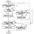
- FIG. 3 is a flowchart for explaining a reference signal determination method in the wireless communication device 1 according to the embodiment.
- the reference signal holding unit 34 (in FIG. 2) is applied to the received signal after the FFT processing in the FFT processing unit 31 (FIG. 2).
- a correlation value is calculated by performing a correlation operation with the reference signal held in FIG. 2) (step S1).
- the correlation calculation is executed by the GI of the received signal and the complex conjugate of the data of the last 64 symbols of the data part of the received signal. This correlation calculation may be performed by a known method.
- the reference signals held in the reference signal holding unit 34 are eight types of reference signals set at intervals of 8 symbols as described above, and each of them performs a correlation operation with the received signal.
- eight types of correlation values are obtained corresponding to the eight cutout positions, and the reference signal selection unit 33 detects peak values (correlation value peaks) among them (step S2).
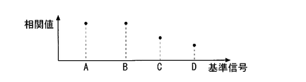
- FIG. 4 is a diagram showing correlation values with respect to the reference signal, and shows correlation values with respect to the reference signals A, B, C, and D.
- the correlation value based on the reference signal A and the correlation value based on the reference signal B are substantially the same, and the correlation values based on the reference signals C and D are smaller than the correlation values based on the reference signals A and B.
- step S2 a correlation value difference is detected in adjacent reference signals, and it is determined that no correlation value peak is detected if the correlation values of adjacent reference signals are substantially the same or the difference between the two is small. .
- the correlation value is compared in order from the cut-out position 0/8 side or the 8/8 side. If there is a difference of a predetermined value or more between the correlation values of adjacent reference signals, Comparison with the correlation value of the next cutout position is performed. By repeating this and ranking the correlation values, the reference signal selection unit 33 prepares for interpolation of the reference signal described in step S7.
- the reference signal A and the correlation value by the reference signal B are substantially the same and higher than the other correlation values, first, first, the reference signal A and the reference signal B Prepare to interpolate between the cutout positions corresponding to. Thereby, the possibility of detecting a correlation value peak can be increased.
- the interpolation procedure is not limited to this procedure.
- the interpolation between the cutout position corresponding to the reference signal A or the reference signal B and the adjacent cutout position may be performed. good. This can cope with a case where the correlation value peak appears at an irregular position.
- the reference signal giving the correlation value is provisionally determined as a reference signal (step S3).
- Step S6 is a step of confirming the number of times of interpolating the reference signal. If the number of times of interpolating the reference signal is less than 4, the process proceeds to step S7 to interpolate the reference signal.
- interpolation refers to the position of the head of the data portion between the already used reference signals. This is to create a new reference signal such that
- step S7 for example, in the example shown in FIG. 4, the correlation value based on the reference signal A and the correlation value based on the reference signal B are substantially the same.
- a new reference signal is generated so as to be the head position of the copy, and the processes in and after step S1 are repeated.
- This result is shown in FIG. In FIG. 5, in addition to the correlation values based on the reference signals A, B, C, and D, the correlation value based on the reference signal ⁇ is shown.
- This reference signal ⁇ is a new reference signal obtained by interpolation.
- FIG. 6 shows a frame of a received signal indicating a cutout position based on the reference signal ⁇ .
- the reference signal A corresponds to the cutout position 1/8 and the reference signal B corresponds to the cutout position 2/8.
- the reference signal ⁇ is set such that the cutout position corresponding to the reference signal A and the reference signal B is the cutout position.
- the reference signal created by interpolation can be created by shifting any of the already created reference signals by a predetermined symbol.
- the reference signal ⁇ can be created by shifting the 1/8 reference signal by 4 symbols.
- step S2 it is determined that the correlation value peak has been detected, and the reference signal giving the correlation value peak is referred to. Temporarily determined as a signal (step S3).
- the reference signal selection unit 33 determines whether or not the correlation value at the position of the temporarily determined reference signal is higher than a preset threshold value (step S4).
- the determined reference signal is determined as a reference signal (step S5).
- FIG. 5 shows a case where the correlation value based on the reference signal ⁇ is higher than the threshold value, and the reference signal ⁇ becomes the reference signal.
- the reference signal selection operation is terminated.
- the threshold is set to about the value of the correlation value when, for example, 4 symbols are deviated from the correlation value peak, but is not limited thereto.
- step S4 determines whether the correlation value in the tentatively determined reference signal is less than a preset threshold value. If it is determined in step S4 that the correlation value in the tentatively determined reference signal is less than a preset threshold value, the operation in step S6 is repeated again to check the number of times the reference signal has been interpolated. If the number of times that the reference signal is interpolated is less than 4, the process proceeds to step S7 and the reference signal is interpolated again.
- FIG. 7 shows a correlation value with respect to the reference signal when the second and third interpolations are performed.
- the correlation value peak is obtained by the third interpolation
- the reference values in the first and second interpolations are shown as the reference signals ⁇ and ⁇ , respectively.
- the correlation values of the reference signals ⁇ and ⁇ are both lower than a preset threshold value, and a correlation value peak is obtained by the reference signal ⁇ in the third interpolation.
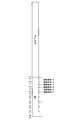
- FIG. 8 shows a frame of the received signal indicating the cutout position by the reference signals ⁇ , ⁇ , and ⁇ .
- the reference signal ⁇ has a cutout position between the cutout position 1/8 and the cutout position 0/8.
- the reference signal ⁇ is set so as to be between the cutout position 2/8 and the cutout position 3/8, and the reference signal ⁇ corresponds to the reference signal A and the reference signal B.
- the cutout position is set to be between the cutout positions to be cut.
- step S2 it is determined that no correlation value peak is detected in step S2, and in step S4, it is determined that there is no correlation value peak higher than a preset threshold value. Since the reference signal is interpolated up to three times, no further interpolation is performed (step S6), and the reference signal selection unit 33 selects the maximum value from the obtained correlation values, and the reference corresponding to the correlation value.
- a signal (including an interpolated signal) is determined as a reference signal (step S8). That is, in the example of FIG. 8, the reference signal ⁇ is a reference signal.
- the number of interpolations is less than 4.
- the number of interpolations is not limited to this, and the number of interpolations can be increased as long as the time spent for interpolation and correlation calculation is within an allowable range.
- interpolation may be performed so as to perform correlation calculation at intervals of one symbol.
- the GI has been described as being composed of 64 symbols, the GI is not limited to this and can be applied to cases where the number of symbols is larger.
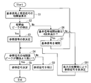
- steps S1 to S7 are the same as those shown in FIG.
- step S2 of FIG. 9 when the correlation value obtained by any one of the reference signals is detected as a correlation value peak that is far higher than the others, the reference signal giving the correlation value is provisionally determined as a reference signal.
- Step S3 If the interpolation of the reference signal is repeated and the number of interpolations exceeds 4, the maximum value is selected from the obtained correlation values in step S81, and the reference signal (interpolated signal) corresponding to the correlation value is selected. Is also temporarily determined as a reference signal.
- the reference signal selection unit 33 determines whether or not the correlation value at the temporarily determined reference signal position is higher than a preset threshold value (step S4).
- the determined reference signal is determined as a reference signal (step S5). If it is determined in step S4 that the correlation value in the temporarily determined reference signal is less than a preset threshold value, the reference signal is corrected (step S9). ).
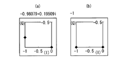
- FIG. 10A shows the phase of an example of the received signal on the I / Q plane
- FIG. 10B shows the phase of the temporarily determined reference signal on the I / Q plane. It is.
- the phase of the received signal is ⁇ 0.98079 + 0.19509i, and the phase of the reference signal is ⁇ 1.
- phase difference (phase rotation amount) between the reference signal and the received signal is calculated by (the phase of the received signal) ⁇ (the phase of the reference signal), and when the above value is substituted for this, it is as follows.
- the reference signal correction process takes longer than the process of detecting the correlation value peak by interpolating the reference signal, a method of temporarily determining the reference signal by interpolating the reference signal and further correcting it is adopted. Thus, it is possible to reduce the time spent for selecting the reference signal and further increase the reference signal selection accuracy.
Landscapes
- Engineering & Computer Science (AREA)
- Computer Networks & Wireless Communication (AREA)
- Signal Processing (AREA)
- Radio Transmission System (AREA)
- Synchronisation In Digital Transmission Systems (AREA)
Abstract
La présente invention comporte une unité de conservation de signaux de référence candidats destinée à conserver une pluralité de signaux de référence candidats, une unité de calcul de valeurs de corrélation destinée à exécuter un calcul de corrélations entre un signal reçu et les différents signaux de référence candidats, et une unité de sélection de signal de référence destinée à déterminer un signal de référence parmi les différents signaux de référence candidats sur la base des résultats de calcul de corrélation dans l'unité de calcul de valeurs de corrélation. L'unité de sélection de signal de référence, dans le cas où un pic de valeur de corrélation qui communique une valeur maximale n'est pas détecté pour les différentes valeurs de corrélation obtenues par le calcul de corrélations entre le signal reçu et les différents signaux de référence candidats, crée un nouveau signal de référence candidat pour lequel les en-têtes des parties de données sont positionnés en des positions entre des intervalles de symboles prédéterminés et répète un nombre prédéterminé de fois un traitement consistant à exécuter le calcul des corrélations entre le nouveau signal de référence candidat et le signal reçu.
Priority Applications (1)
| Application Number | Priority Date | Filing Date | Title |
|---|---|---|---|
| US14/118,145 US9154358B2 (en) | 2011-05-27 | 2012-05-24 | Wireless communication device and method of determining reference signal |
Applications Claiming Priority (2)
| Application Number | Priority Date | Filing Date | Title |
|---|---|---|---|
| JP2011119519A JP5642627B2 (ja) | 2011-05-27 | 2011-05-27 | 無線通信装置および参照信号の決定方法 |
| JP2011-119519 | 2011-05-27 |
Publications (1)
| Publication Number | Publication Date |
|---|---|
| WO2012165292A1 true WO2012165292A1 (fr) | 2012-12-06 |
Family
ID=47259149
Family Applications (1)
| Application Number | Title | Priority Date | Filing Date |
|---|---|---|---|
| PCT/JP2012/063317 Ceased WO2012165292A1 (fr) | 2011-05-27 | 2012-05-24 | Dispositif de communication sans fil et procédé de détermination pour signaux de référence |
Country Status (3)
| Country | Link |
|---|---|
| US (1) | US9154358B2 (fr) |
| JP (1) | JP5642627B2 (fr) |
| WO (1) | WO2012165292A1 (fr) |
Families Citing this family (1)
| Publication number | Priority date | Publication date | Assignee | Title |
|---|---|---|---|---|
| US10103792B2 (en) * | 2016-01-14 | 2018-10-16 | Intel Corporation | Apparatus, system and method of communicating a multiple-input-multiple-output (MIMO) transmission |
Citations (4)
| Publication number | Priority date | Publication date | Assignee | Title |
|---|---|---|---|---|
| JPH1141141A (ja) * | 1997-05-21 | 1999-02-12 | Mitsubishi Electric Corp | スペクトル拡散信号受信方法及びスペクトル拡散信号受信装置 |
| JP2002232386A (ja) * | 2001-01-30 | 2002-08-16 | Sony Corp | アダプティブアレーを用いたofdm受信装置 |
| JP2003110459A (ja) * | 2001-09-28 | 2003-04-11 | Matsushita Electric Ind Co Ltd | 無線受信装置及び無線受信方法 |
| JP2010278663A (ja) * | 2009-05-27 | 2010-12-09 | Kyocera Corp | 無線通信装置及びタイミング推定方法 |
Family Cites Families (6)
| Publication number | Priority date | Publication date | Assignee | Title |
|---|---|---|---|---|
| JP3486576B2 (ja) * | 1999-05-18 | 2004-01-13 | シャープ株式会社 | Ofdm受信装置及びその周波数オフセット補償方法 |
| JP3697125B2 (ja) * | 1999-12-15 | 2005-09-21 | 松下電器産業株式会社 | Ofdm通信装置およびofdm通信方法 |
| JP2008153927A (ja) | 2006-12-18 | 2008-07-03 | Sanyo Electric Co Ltd | 無線受信装置 |
| JP5381153B2 (ja) * | 2009-02-23 | 2014-01-08 | 日本電気株式会社 | 無線受信機、受信レベル測定方法、受信レベル測定プログラムおよびプログラム記録媒体 |
| JP5695399B2 (ja) * | 2010-11-26 | 2015-04-01 | 京セラ株式会社 | 通信装置および無線通信方法 |
| JP5581230B2 (ja) * | 2011-01-07 | 2014-08-27 | 株式会社Nttドコモ | 無線基地局装置及び無線通信方法 |
-
2011
- 2011-05-27 JP JP2011119519A patent/JP5642627B2/ja not_active Expired - Fee Related
-
2012
- 2012-05-24 US US14/118,145 patent/US9154358B2/en not_active Expired - Fee Related
- 2012-05-24 WO PCT/JP2012/063317 patent/WO2012165292A1/fr not_active Ceased
Patent Citations (4)
| Publication number | Priority date | Publication date | Assignee | Title |
|---|---|---|---|---|
| JPH1141141A (ja) * | 1997-05-21 | 1999-02-12 | Mitsubishi Electric Corp | スペクトル拡散信号受信方法及びスペクトル拡散信号受信装置 |
| JP2002232386A (ja) * | 2001-01-30 | 2002-08-16 | Sony Corp | アダプティブアレーを用いたofdm受信装置 |
| JP2003110459A (ja) * | 2001-09-28 | 2003-04-11 | Matsushita Electric Ind Co Ltd | 無線受信装置及び無線受信方法 |
| JP2010278663A (ja) * | 2009-05-27 | 2010-12-09 | Kyocera Corp | 無線通信装置及びタイミング推定方法 |
Also Published As
| Publication number | Publication date |
|---|---|
| JP5642627B2 (ja) | 2014-12-17 |
| JP2012249095A (ja) | 2012-12-13 |
| US9154358B2 (en) | 2015-10-06 |
| US20140093020A1 (en) | 2014-04-03 |
Similar Documents
| Publication | Publication Date | Title |
|---|---|---|
| CN108832965B (zh) | 一种确定上行同步定时偏差的方法及装置 | |
| JP6118616B2 (ja) | 受信機および同期補正方法 | |
| JP4488605B2 (ja) | Ofdm信号の伝送方法、送信装置及び受信装置 | |
| JP4145240B2 (ja) | ダイバーシチ受信方法および装置 | |
| US8045538B2 (en) | Wireless communication method, receiving method, and wireless communication device | |
| JP2004320738A (ja) | Ofdm受信装置 | |
| EP1780921A1 (fr) | Dispositif de detection de signal perturbant et dispositif de reception ofdm utilisant celui-ci | |
| WO2014017137A1 (fr) | Dispositif de réception, terminal de transmission et de réception, procédé de mesure de temps de retard de propagation, et programme d'ordinateur | |
| US20090323591A1 (en) | Receiving Apparatus, Receiving Method and Wireless Communication System | |
| JP5642627B2 (ja) | 無線通信装置および参照信号の決定方法 | |
| JP5055239B2 (ja) | Ofdm復調装置 | |
| CN104901918B (zh) | 基于Chirp信号产生OFDM数据序列的方法及同步方法 | |
| JP2018516494A (ja) | アンテナ故障の補償方法及び装置 | |
| JP6266169B2 (ja) | 送信装置、受信装置および通信システム | |
| JP5284891B2 (ja) | 通信装置及び遅延量検出方法 | |
| JP5717585B2 (ja) | タイミング検出装置 | |
| JP4362142B2 (ja) | 遅延プロファイル生成器 | |
| JP5398652B2 (ja) | Ofdm受信装置 | |
| JP5275304B2 (ja) | Ofdm受信装置 | |
| JP2009171266A (ja) | 自動周波数制御方法および装置 | |
| JP5323462B2 (ja) | 無線通信システム | |
| JP2004158933A (ja) | 同期追従装置及び方法 | |
| JP6324260B2 (ja) | 受信装置 | |
| JP6821869B2 (ja) | Ofdm受信装置およびofdm受信方法 | |
| JP2014039088A (ja) | 無線通信装置 |
Legal Events
| Date | Code | Title | Description |
|---|---|---|---|
| 121 | Ep: the epo has been informed by wipo that ep was designated in this application |
Ref document number: 12792565 Country of ref document: EP Kind code of ref document: A1 |
|
| WWE | Wipo information: entry into national phase |
Ref document number: 14118145 Country of ref document: US |
|
| NENP | Non-entry into the national phase |
Ref country code: DE |
|
| 122 | Ep: pct application non-entry in european phase |
Ref document number: 12792565 Country of ref document: EP Kind code of ref document: A1 |