WO2012165346A1 - Dispositif optique - Google Patents
Dispositif optique Download PDFInfo
- Publication number
- WO2012165346A1 WO2012165346A1 PCT/JP2012/063525 JP2012063525W WO2012165346A1 WO 2012165346 A1 WO2012165346 A1 WO 2012165346A1 JP 2012063525 W JP2012063525 W JP 2012063525W WO 2012165346 A1 WO2012165346 A1 WO 2012165346A1
- Authority
- WO
- WIPO (PCT)
- Prior art keywords
- holding member
- optical
- optical coupling
- coupling member
- end portion
- Prior art date
- Legal status (The legal status is an assumption and is not a legal conclusion. Google has not performed a legal analysis and makes no representation as to the accuracy of the status listed.)
- Ceased
Links
Images


Classifications
-
- G—PHYSICS
- G02—OPTICS
- G02B—OPTICAL ELEMENTS, SYSTEMS OR APPARATUS
- G02B6/00—Light guides; Structural details of arrangements comprising light guides and other optical elements, e.g. couplings
- G02B6/24—Coupling light guides
- G02B6/26—Optical coupling means
-
- G—PHYSICS
- G02—OPTICS
- G02B—OPTICAL ELEMENTS, SYSTEMS OR APPARATUS
- G02B6/00—Light guides; Structural details of arrangements comprising light guides and other optical elements, e.g. couplings
- G02B6/24—Coupling light guides
- G02B6/26—Optical coupling means
- G02B6/264—Optical coupling means with optical elements between opposed fibre ends which perform a function other than beam splitting
-
- G—PHYSICS
- G02—OPTICS
- G02B—OPTICAL ELEMENTS, SYSTEMS OR APPARATUS
- G02B6/00—Light guides; Structural details of arrangements comprising light guides and other optical elements, e.g. couplings
- G02B6/24—Coupling light guides
- G02B6/36—Mechanical coupling means
- G02B6/38—Mechanical coupling means having fibre to fibre mating means
- G02B6/3807—Dismountable connectors, i.e. comprising plugs
- G02B6/3873—Connectors using guide surfaces for aligning ferrule ends, e.g. tubes, sleeves, V-grooves, rods, pins, balls
- G02B6/3874—Connectors using guide surfaces for aligning ferrule ends, e.g. tubes, sleeves, V-grooves, rods, pins, balls using tubes, sleeves to align ferrules
- G02B6/3877—Split sleeves
Definitions
- the present invention relates to an optical device having a light guide member and an optical element.
- Patent Document 1 discloses an optical component that can be attached to an end portion of a light guide member.
- the cap (holder) includes a first fitting portion formed as a hole into which the ferrule is fitted, and a second fitting formed as a hole communicating with the first fitting portion (hole).
- An arrangement portion having a joint portion is included.
- the ferrule is fixed to the holder by YAG welding at least one place on the side surface of the ferrule to the first fitting portion.
- the ferrule can also be fixed to the holder by an adhesive, resistance welding, press-fitting, caulking, or the like.
- the ferrule can also be fixed to the holder at the end of the ferrule.
- An optical element (light converting member) is disposed in the second fitting portion.
- the optical element is fixed to the holder by fixing the optical element to the second fitting portion with melting point glass or resin.
- Patent Document 1 in order for the ferrule to be fixed to the holder, there is no gap between the ferrule and the holder, and the ferrule needs to be fitted to the holder while the ferrule is in close contact with the holder. In this state, the ferrule is fixed to the holder by YAG welding, adhesive, resistance welding, press fitting, caulking, or the like.
- the tolerance (tightening allowance) between the ferrule and the holder the greater the load for press-fitting.
- distortion is likely to occur in the optical fiber and the optical element, and the optical performance is further deteriorated by the load when the optical device is assembled.
- the greater the tolerance (tightening allowance) the lower the optical performance due to the load during assembly.
- the present invention has been made in view of these circumstances, and an object thereof is to provide an optical device that prevents a decrease in optical performance caused by a load during assembly.
- the light guide member that guides light, the first holding member that holds the light guide member, and the light guided by the light guide member are irradiated.
- an optical device that prevents a decrease in optical performance caused by a load during assembly.
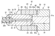
- FIG. 1A is an exploded perspective view of an optical device before optical coupling according to the first embodiment of the present invention.
- FIG. 1B is a schematic view of the optical connector after optical coupling.
- FIG. 2A is a diagram illustrating a modification of the optical coupling member.
- FIG. 2B is a diagram illustrating a modification of the optical coupling member.
- FIG. 2C is a diagram illustrating a modification of the optical coupling member.
- FIG. 2D is a diagram illustrating a modification of the optical coupling member.
- FIG. 3 is a diagram illustrating a modification of the second holding member according to the first modification of the first embodiment of the present invention.
- FIG. 4A relates to a second modification of the first embodiment of the present invention, in which at least one of the first holding member and the second holding member is connected to the optical coupling member by a connecting mechanism. It is a figure.
- FIG. 4B relates to a second modification of the first embodiment of the present invention, in which at least one of the first holding member and the second holding member is connected to the optical coupling member by a connecting mechanism. It is a figure.
- the optical device 10 includes a light guide member such as an optical fiber 21 that guides light, a first holding member 31 that holds the optical fiber 21, and the optical fiber 21. It has an optical element 41 that functions by being irradiated with the guided light, and a second holding member 51 that holds the optical element 41.
- optical fiber 21 As shown in FIG. 1B, the optical fiber 21 is disposed at one end portion 23 of the optical fiber 21 and has an emission end face 23a that emits light. The other end 25 of the optical fiber 21 is covered with, for example, a resin coating layer 25 a that protects the optical fiber 21.
- the optical fiber 21 is made of, for example, glass or plastic.
- the first holding member 31 has a ferrule formed of, for example, zirconia, glass, metal, or the like. This metal includes, for example, nickel and SUS.
- the first holding member 31 has, for example, a cylindrical shape. Specifically, as shown in FIG. 1B, the first holding member 31 has a through hole 31a that is disposed on the central axis of the first holding member 31 and into which the optical fiber 21 is fitted or bonded. Yes.
- the through hole 31 a passes through the first holding member 31 in the axial direction of the first holding member 31.
- the through hole 31a is provided for the first holding member 31 to hold the optical fiber 21, and functions as a holding hole.
- the first holding member 31 holds the optical fiber 21 so that the emission end face 23 a of the optical fiber 21 is disposed on the same plane as the one end face 31 b of the first holding member 31. At this time, the emission end face 23a and the one end face 31b are disposed so as to be located on the same plane.
- the one end surface 31 b is disposed at one end portion 33 of the first holding member 31.
- the through hole 31a is open at one end surface 31b.
- the periphery of the opening of the through hole 31a is formed as a flat surface, for example.
- the edge side of the first holding member 31 on the one end surface 31 b is reduced in diameter from the other end surface 31 c side of the first holding member 31 toward the one end surface 31 b side in the axial direction of the first holding member 31.
- it is formed in a tapered shape.
- the one end portion 33 of the first holding member 31 extends from the other end surface 31 c side of the first holding member 31 to the one end surface 31 b side of the first holding member 31 in the axial direction of the first holding member 31. It has a truncated cone shape that is reduced in diameter.
- the one end portion 33 functions as an insertion portion inserted into the optical coupling member 61 in order to be press-fitted into the optical coupling member 61 described later.
- the outer diameter of the one end portion 33 is larger than the inner diameter of the optical coupling member 61 because the one end portion 33 is press-fitted into the optical coupling member 61.
- the first holding member 31 has a guide opening 31d that is disposed on the other end surface 31c of the first holding member 31 and communicates with the through hole 31a.
- the guide port portion 31d guides the one end portion 23 of the optical fiber 21 to the through hole 31a so that the optical fiber 21 is inserted and fitted into the through hole 31a.
- the guide opening 31d and the other end surface 31c are disposed at the other end 35 of the first holding member 31.
- the guide port portion 31d has a truncated cone shape that is reduced in diameter from the other end surface 31c of the first holding member 31 toward the one end surface 31b side of the first holding member 31 and is tapered. It is formed into a shape.
- the above-described coating layer 25a is disposed only on the other end surface 31c side of the first holding member 31, specifically, near the guide opening 31d, and is not inserted into the through hole 31a. For this reason, the one end part 23 of the optical fiber 21 is exposed from the coating layer 25a.
- an adhesive member 37 for adhering the other end portion 25 side of the optical fiber 21 including the coating layer 25a to the first holding member 31 is disposed.
- the adhesive member 37 is also disposed on the covering layer 25a.
- the adhesive member 37 includes, for example, an optical adhesive or an adhesive such as silicon or epoxy.
- the optical element 41 is made of, for example, ceramic or glass.
- the optical element 41 has, for example, a cylindrical shape.
- the optical element 41 is not limited to a cylindrical shape, and may be a conical shape, a truncated cone shape, a hemispherical shape, or a parabolic shape.
- the diameter of the optical element 41 is larger than the diameter of the optical fiber 21, for example.
- the optical element 41 has, for example, a planar end face 43a.
- the one end face 43a abuts on the emission end face 23a so that the optical fiber 21 and the optical element 41 are optically coupled.
- the one end face 43a functions as an incident end face on which light emitted from the emission end face 23a is incident.
- the one end face 43a is larger than the emission end face 23a.
- the optical element 41 is disposed coaxially with the optical fiber 21 and is optically coupled to the optical fiber 21. At this time, at least the central axis of the one end face 43a is disposed coaxially with the central axis of the emission end face 23a, and the one end face 43a is optically connected to the emission end face 23a.
- the second holding member 51 is formed of a metal such as nickel, SUS, or brass.
- the second holding member 51 is a separate body from the first holding member 31.
- the second holding member 51 is formed in a stepped shape, and thus has, for example, a convex outer shape.
- Such a second holding member 51 is composed of one end portion 53 and the other end portion 55 that is larger (thicker) than the one end portion 53.
- the one end portion 53 and the other end portion 55 have, for example, a cylindrical shape. In this case, the one end portion 53 is formed as a small diameter portion, and the other end portion 55 is formed as a large diameter portion.
- the one end portion 53 is connected to the other end portion 55.
- the one end portion 53 functions as an insertion portion inserted into the optical coupling member 61 in order to be press-fitted into the optical coupling member 61 described later.
- the outer diameter of the one end portion 53 is larger than the inner diameter of the optical coupling member 61 because the one end portion 53 is press-fitted into the optical coupling member 61.
- the one end portion 53 of the second holding member 51 that functions as the insertion portion is inserted into the optical coupling member 61, so that it is another part such as the other end portion 55 disposed outside the optical coupling member 61. Thinner than.
- the outer diameter of the one end portion 53 is substantially the same as the outer diameter of the one end portion 33 of the first holding member 31 inserted into the optical coupling member 61.
- the one end portion 53 faces the one end portion 33 of the first holding member 31 when the optical fiber 21 and the optical element 41 are optically coupled.
- the one end portion 53 has a flat one end surface 53 a that contacts the one end surface 31 b of the first holding member 31.
- the other end 55 has a flat one end surface 55a that comes into contact with one end 63 of an optical coupling member 61 described later.
- the outer diameter of the other end 55 is larger than the inner diameter of the optical coupling member 61.
- the outer diameter of the other end portion 55 is substantially the same as the outer diameter of the optical coupling member 61 or smaller than the outer diameter of the optical coupling member 61.
- the second holding member 51 is disposed on the central axis of the second holding member 51, and has a through hole 51a into which the optical element 41 is fitted or adhered.
- the through hole 51 a passes through the second holding member 51 (one end portion 53 and the other end portion 55) in the axial direction of the second holding member 51.
- the through hole 51a is provided for the second holding member 51 to hold the optical element 41, and functions as a holding hole.
- the second holding member 51 holds the optical element 41 so that the one end face 43 a of the optical element 41 is disposed on the same plane as the one end face 53 a of the one end portion 53. At this time, the one end face 43a and the one end face 53a are disposed so as to be located on the same plane.
- optical coupling member 61 Further, the optical device 10 is elastically deformed by inserting the one end portion 33 of the first holding member 31 and the one end portion 53 of the second holding member 51, and the optical fiber 21 and the optical element 41 are deformed by elastic deformation.
- An optical coupling member 61 for optical coupling is further included.
- the optical coupling member 61 is formed of, for example, a spring material such as zirconia, nickel, or phosphor bronze, and has an elastic force for elastic deformation.
- the first end surface 23a and the one end surface 43a are in contact with each other.
- One end portion 33 of the holding member 31 and one end portion 53 of the second holding member 51 are press-fitted into the optical coupling member 61 and fitted into the optical coupling member 61.
- One end 53 of the second holding member 51 is press-fitted from one end 63 of the optical coupling member 61, and one end 33 of the first holding member 31 is press-fitted from the other end 65 of the optical coupling member 61.
- the inner peripheral surface of the optical coupling member 61 is brought into close contact with the outer peripheral surface of the one end portion 33 that functions as the insertion portion and the outer peripheral surface of the one end portion 53 that functions as the insertion portion by press-fitting.
- the optical coupling member 61 also presses and tightens the first holding member 31 (one end portion 33) and the second holding member 51 (one end portion 53) in the radial direction.
- the first holding member 31 (one end portion 33) and the second holding member 51 (one end portion 53) are aligned, for example, in the radial direction, and the optical coupling member 61 has the optical fiber 21 (the emission end face 23a) and the optical element 41.
- End surface 43a) is coaxially disposed, the output end surface 23a and the one end surface 43a are optically coupled to each other, and the optical coupling member 61 connects the optical fiber 21 and the optical element 41 at the time of press-fitting. For example, it is elastically deformed so as to expand in the radial direction.
- the optical coupling member 61 is both a positioning member and a connecting member.
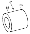
- Such an optical coupling member 61 is formed such that a part of the cross section of the optical coupling member 61 is notched in order to promote the elastic deformation of the optical coupling member 61 depending on the elastic force described above.
- the optical coupling member 61 is configured to reduce the force that the optical coupling member 61 tightens the one end portion 33 of the first holding member 31 and the one end portion 53 of the second holding member 51 in the radial direction during press-fitting.
- the coupling member 61 is formed so that a part of the cross section is cut out. For this reason, for example, the optical coupling member 61 is formed as a substantially cylindrical member having a cross-section partially cut off in the axial direction.
- This cross section is formed in a plane direction orthogonal to the axial direction of the optical coupling member 61. Moreover, this cross section is formed in C shape, for example.
- the optical coupling member 61 is formed, for example, as a substantially cylindrical shape having a C-shaped cross section continuously in the axial direction.
- the optical coupling member 61 is formed as a split sleeve in which a part of a circle is notched. Therefore, the optical coupling member 61 has a slit 61 a that is disposed along the axial direction of the optical coupling member 61 and penetrates the optical coupling member 61 in the axial direction.
- the slit 61 a penetrates the optical coupling member 61 in the thickness direction of the optical coupling member 61.
- the slit 61 a is formed by cutting out a part of the cross section of the optical coupling member 61.
- the optical coupling member 61 is separate from the first holding member 31 and the second holding member 51. Specifically, the optical coupling member 61 is separate from the one end portion 33 that functions as an insertion portion in the first holding member 31 and the one end portion 53 that functions as an insertion portion in the second holding member 51. Therefore, as described above, the one end portion 53 of the second holding member 51 can be press-fitted into the optical coupling member 61 from the one end portion 63 of the optical coupling member 61, and the one end portion 33 of the first holding member 31 is the optical coupling member. It is possible to press-fit the optical coupling member 61 from one end 63 of the 61.
- the one end 63 of the optical coupling member 61 is not fixed to the one end 53 of the second holding member 51, and the other end 65 of the optical coupling member 61 is connected to the one end 33 of the first holding member 31. It is not fixed. That is, both ends of the optical coupling member 61 are not fixed ends but free ends. Therefore, even if the load of this embodiment is small compared with the load in the case where the optical coupling member 61 is integral with either the first holding member 31 or the second holding member 51, the first holding member 31 ( The one end portion 33) and the second holding member 51 (one end portion 53) are press-fitted into the optical coupling member 61.
- a force for fastening the one end portion 33 of the first holding member 31 and the one end portion 53 of the second holding member 51 in the radial direction is expressed as a first fastening force. Called.
- the optical coupling member 61 is formed in, for example, a cylindrical shape without cutting out a part of the cross section of the optical coupling member 61, the optical coupling member 61 is the first holding member 31.
- the force that tightens the one end portion 33 of the second and the one end portion 53 of the second holding member 51 in the radial direction is referred to as a second tightening force.
- the first tightening force in the present embodiment is adjusted to be smaller than the second tightening force, for example, by arranging the slit 61a. For this reason, even if the load of this embodiment is small compared with the load in the case where the optical coupling member 61 is formed in, for example, a cylindrical shape without a part of the cross section of the optical coupling member 61 being cut out, the first The holding member 31 (one end portion 33) and the second holding member 51 (one end portion 53) are press-fitted into the optical coupling member 61.
- the optical coupling member 61 is adjusted by elastic deformation, that the optical coupling member 61 is a separate body from the first holding member 31 and the second holding member 51, and that a part of the cross section is cut away.
- the first tightening force that is applied controls, adjusts, and suppresses the load applied to the first holding member 31 and the second holding member 51 along the axial direction of the optical device 10 by press-fitting.
- the optical element 41 is disposed in the through hole 51 a, and the second holding member 51 holds the optical element 41.
- the optical fiber 21 is disposed in the through hole 31a from the guide opening 31d, and the adhesive member 37 is disposed in the guide opening 31d to bond the optical fiber 21 including the coating layer 25a to the first holding member 31. . Thereby, the first holding member 31 holds the optical fiber 21.
- the one end portion 53 of the second holding member 51 that functions as an insertion portion is press-fitted into the optical coupling member 61 so that the one end surface 55 a of the other end portion 55 abuts on the one end portion 63 of the optical coupling member 61.
- the one end portion 33 of the first holding member 31 that functions as the insertion portion is press-fitted into the optical coupling member 61 so that the emission end surface 23 a and the one end surface 43 a are in contact with each other.
- the optical coupling member 61 When the one end portion 53 of the second holding member 51 and the one end portion 33 of the first holding member 31 are press-fitted into the optical coupling member 61, the optical coupling member 61 is elastically deformed, for example, in the radial direction. Further, this elastic deformation is promoted by the slit 61a. And the optical coupling member 61 presses the 1st holding member 31 (one end part 33) and the 2nd holding member 51 (one end part 53) to radial direction by elastic deformation. Thereby, the optical coupling member 61 aligns the first holding member 31 and the second holding member 51 in the radial direction, for example, so that the optical fiber 21 (the emission end face 23a) and the optical element 41 (the one end face 43a) are aligned. Are arranged on the same axis to connect the optical fiber 21 and the optical element 41. Therefore, the optical fiber 21 (outgoing end face 23a) and the optical element 41 (one end face) are optically coupled.
- the optical coupling member 61 expands in diameter direction, for example. Elastically deforms.
- the load of this embodiment may be smaller than the load when the optical coupling member 61 does not elastically deform in the radial direction. Therefore, distortion is prevented from occurring in the optical fiber 21 and the optical element 41 due to the load, and a decrease in optical performance caused by the load during assembly is prevented.
- the optical coupling member 61 is separate from the first holding member 31 and the second holding member 51. For this reason, at the time of press-fitting, the load of the present embodiment may be smaller than the load when the optical coupling member 61 is integral with either the first holding member 31 or the second holding member 51. Therefore, it is possible to prevent distortion from occurring in the optical fiber 21 and the optical element 41 due to the load, and further prevent deterioration in optical performance caused by the load during assembly.
- the first tightening force is smaller than the second tightening force due to the arrangement of the slit 61a, for example.
- the load of the present embodiment can be smaller than the load when the optical coupling member 61 is formed in, for example, a cylindrical shape without cutting out a part of the cross section of the optical coupling member 61. . Therefore, distortion is prevented from occurring in the optical fiber 21 and the optical element 41 due to the load, and a decrease in optical performance caused by the load during assembly is prevented.
- the optical coupling member 61 when the first holding member 31 (one end portion 33) and the second holding member 51 (one end portion 53) are press-fitted into the optical coupling member 61, the optical coupling member 61 has a diameter of, for example, By elastically deforming so as to increase the diameter in the direction, the load can be made smaller than the load when the optical coupling member 61 does not elastically deform in the radial direction. Therefore, in this embodiment, it can prevent that distortion arises in the optical fiber 21 and the optical element 41 with a load, and can prevent the fall of the optical performance produced by a load at the time of an assembly.
- the optical coupling member 61 is formed so that a part of the cross section of the optical coupling member 61 is cut out. Thereby, in this embodiment, elastic deformation can be accelerated
- the optical coupling member 61 is formed so that a part of the cross section of the optical coupling member 61 is cut out.
- the 1st clamping force can be made smaller than the 2nd clamping force
- the optical coupling member 61 is cylindrical, for example, without a part of a section of optical coupling member 61 being notched. It can be made smaller than the load in the case where it is formed. Therefore, in this embodiment, it can further prevent that distortion arises in the optical fiber 21 and the optical element 41 with a load, and can further prevent the optical performance fall caused by the load at the time of assembly.
- the optical coupling member 61 is separated from the first holding member 31 and the second holding member 51.
- the both ends of the optical coupling member 61 can be made free ends instead of fixed ends.
- the load can be reduced as compared with the load when the optical coupling member 61 is integral with either the first holding member 31 or the second holding member 51. Therefore, in this embodiment, it can further prevent that distortion arises in the optical fiber 21 and the optical element 41 with a load, and can further prevent the optical performance fall caused by the load at the time of assembly.
- the optical coupling member 61 is formed in, for example, a cylindrical shape, and the optical coupling member 61 is either the first holding member 31 or the second holding member 51.
- the outer diameter of the first holding member 31 and the second holding member are used. It is necessary to process the outer diameter of the member 51 and the inner diameter of the optical coupling member 61 with high accuracy. However, this increases the processing cost of the optical device 10.
- the load can be reduced by the above, and distortion is generated in the optical fiber 21 and the optical element 41 due to the load. This can prevent the deterioration of the optical performance caused by the load during assembly. Moreover, in this embodiment, by the above, it can prevent that distortion arises in the optical fiber 21 and the optical element 41 with a load in the state which suppressed processing cost, and can prevent the fall of the optical performance produced by a load at the time of an assembly.
- the elastic deformation described above, the first tightening force adjusted by cutting a part of the cross section, and the optical coupling member 61 include the first holding member 31 and the second holding member 51.
- the load applied to the first holding member 31 and the second holding member 51 along the axial direction of the optical device 10 by press-fitting at the time of press-fitting. Therefore, in this embodiment, it can prevent that distortion arises in the optical fiber 21 and the optical element 41 with a load, and optical performance falls by a load at the time of an assembly.
- the optical fiber 21 and the optical element 41 can be prevented from being damaged by the load.
- the present embodiment it is possible to suppress the load variation at the time of press-fitting that varies depending on the shape and size of the first holding member 31, the second holding member 51, and the optical coupling member 61. Moreover, in this embodiment, the load at the time of press-fitting which changes with the shape and magnitude
- the one end portion 53 of the second holding member 51 is press-fitted into the optical coupling member 61
- the one end portion 33 of the first holding member 31 having the same diameter as the one end portion 53 is attached to the optical coupling member 61. Since it is press-fitted, variation in the fitting width can be suppressed and the load can be stabilized.
- the one end portion 53 of the second holding member 51 and the one end portion 33 of the first holding member 31 may be simultaneously press-fitted into the optical coupling member 61.
- the second holding member 51 when the one end portion 53 of the second holding member 51 is press-fitted into the optical coupling member 61, the one end surface 55 a of the other end portion 55 abuts on the one end portion 63 of the optical coupling member 61. Accordingly, in the present embodiment, the second holding member 51 can be easily positioned with respect to the optical coupling member 61. Further, in the present embodiment, after the one end portion 53 of the second holding member 51 is press-fitted into the optical coupling member 61, one end of the first holding member 31 is arranged so that the emission end face 23a and the one end face 43a abut each other. The portion 33 is press-fitted into the optical coupling member 61. Therefore, in this embodiment, the optical coupling member 61 can be easily positioned with respect to the second holding member 51 and the first holding member 31.
- the one end portions 33 and 53 can be press-fitted into the optical coupling member 61, and the optical fiber 21, the optical element 41, and the like.
- the connection strength can be increased.
- the optical fiber 21 and the optical element 41 can be easily positioned, and deviation during optical coupling can be prevented.
- the one end portions 33 and 53 function as insertion portions, so that positioning for optical coupling can be maintained with high accuracy.
- the optical fibers 21 and the optical element 41 can be easily aligned because the one end portions 33 and 53 function as insertion portions.
- the second holding member 51 has, for example, a convex outer shape, and the outer diameter of the other end 55 is substantially the same as the outer diameter of the optical coupling member 61 or the outer diameter of the optical coupling member 61. Smaller than. For this reason, in this embodiment, the optical device 10 can be reduced in size while ensuring the strength of the second holding member 51.
- the optical device 10 can be easily assembled by press-fitting the one end portions 33 and 53 into the optical coupling member 61 without using an adhesive or the like.
- the first holding member 31, the second holding member 51, and the optical coupling member 61 are formed of the same material (for example, nickel) without using an adhesive or the like. High reliability can be ensured, and in this state, it can be optically coupled.
- the optical device 10 further includes a cover member that closely contacts and covers the first holding member 31, the second holding member 51, and the optical coupling member 61 in order to further secure the connection strength. You may have.
- the optical coupling member 61 is a split sleeve, but it is not necessary to limit to this.
- the optical coupling member 61 may be formed as a cylindrical member as shown in FIG. 2A. . Even in this case, the effects described above can be obtained in the present embodiment.
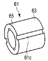
- the optical coupling member 61 may be formed as a cylindrical member having a cross-section with a part cut away.
- the optical coupling member 61 may have, for example, a groove 61 c disposed along the axial direction of the optical coupling member 61.
- the groove 61c may be recessed from the outer peripheral surface of the optical coupling member 61 toward the inner peripheral surface, or may be recessed from the inner peripheral surface of the optical coupling member 61 toward the outer peripheral surface.
- the arrangement position and shape of the groove 61c are not particularly limited.
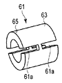
- the optical coupling member 61 may have a slit 61a that does not penetrate through the optical coupling member 61 in the axial direction.
- the optical coupling member 61 may have a plurality of slits 61a.
- the arrangement position and shape of the slit 61a are not particularly limited.
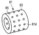
- the optical coupling member 61 may have a hole 61 d that penetrates the optical coupling member 61 in the thickness direction of the optical coupling member 61.
- the arrangement position and shape of the hole 61d are not particularly limited.
- the optical coupling member 61 may be formed as a cylindrical member having at least one of a slit 61a, a groove 61c, and a hole 61d.
- the one end portion 53 has substantially the same diameter as the other end portion 55. Further, since the one end portion 53 is press-fitted into the optical coupling member 61, the outer diameter of the one end portion 53 and the outer diameter of the other end portion 55 are larger than the inner diameter of the optical coupling member 61. The outer diameter of the one end portion 53 and the outer diameter of the other end portion 55 are substantially the same as the outer diameter of the one end portion 33 of the first holding member 31 inserted into the optical coupling member 61.
- the second holding member 51 has a cylindrical shape. Since the one end portion 53 is press-fitted into the optical coupling member 61, the outer diameter of the second holding member 51 is larger than the inner diameter of the optical coupling member 61. The outer diameter of the second holding member 51 is substantially the same as the outer diameter of the one end portion 33 of the first holding member 31 inserted into the optical coupling member 61.
- the second holding member 51 can be easily processed, and the cost can be reduced.
- the optical device 10 of this modification has a fixing mechanism 71 that fixes at least one of the first holding member 31 and the second holding member 51 to the optical coupling member 61.
- the fixing mechanism 71 has, for example, at least one of laser welding, solder bonding, an adhesive, and surface activated bonding.
- the laser welding, the solder joint, and the adhesive are implemented and disposed on, for example, one end surface 55a and one end 63 of the other end 55, and the second holding member 51 and the optical coupling member 61 are disposed. And fix. Further, the laser welding, the solder joint, and the adhesive are, for example, implemented and arranged on the outer peripheral surface of the first holding member 31 and the other end portion 65, and fix the first holding member 31 and the optical coupling member 61. .
- the surface activated bonding is performed by, for example, an Au film having an inner peripheral surface of the optical coupling member 61, an outer peripheral surface of the first holding member 31, and an outer periphery of the one end 53 in the second holding member 51. Implemented and disposed on at least one of the surfaces.
- the fixing mechanism 71 can reinforce the fixing strength, and a higher fixing strength can be obtained. In this embodiment, even if the optical device 10 is downsized, the fixing mechanism 71 can ensure high fixing strength.
- the laser welding, solder joint, and adhesive shown in FIG. 4A are disposed outside the optical fiber 21 and the optical element 41, and are disposed outside the optical coupling member 61.
- a high fixing strength can be secured in a state where the coupling efficiency is secured.
- the present invention is not limited to the above-described embodiment as it is, and can be embodied by modifying the constituent elements without departing from the scope of the invention in the implementation stage. Further, various inventions can be formed by appropriately combining a plurality of constituent elements disclosed in the embodiment.
Landscapes
- Physics & Mathematics (AREA)
- General Physics & Mathematics (AREA)
- Optics & Photonics (AREA)
- Optical Couplings Of Light Guides (AREA)
- Mechanical Coupling Of Light Guides (AREA)
Abstract
L'invention concerne un dispositif optique (10) qui comprend : une fibre optique (21) par exemple destinée à guider la lumière ; un premier élément de maintien (31) destiné à maintenir la fibre optique (21) ; un élément optique (41) qui fonctionne par irradiation de la lumière guidée par la fibre optique (21) ; et un second élément de maintien (51) destiné à maintenir l'élément optique (41). Le dispositif optique (10) de plus comporte un élément de couplage optique (61) qui est déformé élastiquement par une section d'extrémité (33) du premier élément de maintien (31) et une section d'extrémité (53) du second élément de maintien (51) qui y sont insérées et couple optiquement la fibre optique (21) et l'élément optique (41) au moyen de la déformation élastique.
Priority Applications (1)
| Application Number | Priority Date | Filing Date | Title |
|---|---|---|---|
| US14/081,346 US9146356B2 (en) | 2011-05-27 | 2013-11-15 | Optical device |
Applications Claiming Priority (2)
| Application Number | Priority Date | Filing Date | Title |
|---|---|---|---|
| JP2011119145A JP5913837B2 (ja) | 2011-05-27 | 2011-05-27 | 光学デバイス |
| JP2011-119145 | 2011-05-27 |
Related Child Applications (1)
| Application Number | Title | Priority Date | Filing Date |
|---|---|---|---|
| US14/081,346 Continuation US9146356B2 (en) | 2011-05-27 | 2013-11-15 | Optical device |
Publications (1)
| Publication Number | Publication Date |
|---|---|
| WO2012165346A1 true WO2012165346A1 (fr) | 2012-12-06 |
Family
ID=47259202
Family Applications (1)
| Application Number | Title | Priority Date | Filing Date |
|---|---|---|---|
| PCT/JP2012/063525 Ceased WO2012165346A1 (fr) | 2011-05-27 | 2012-05-25 | Dispositif optique |
Country Status (3)
| Country | Link |
|---|---|
| US (1) | US9146356B2 (fr) |
| JP (1) | JP5913837B2 (fr) |
| WO (1) | WO2012165346A1 (fr) |
Cited By (1)
| Publication number | Priority date | Publication date | Assignee | Title |
|---|---|---|---|---|
| US10422936B2 (en) | 2016-09-30 | 2019-09-24 | Nichia Corporation | Lighting device |
Families Citing this family (1)
| Publication number | Priority date | Publication date | Assignee | Title |
|---|---|---|---|---|
| US9322998B2 (en) * | 2013-01-15 | 2016-04-26 | Corning Cable Systems Llc | Fiber optic connector |
Citations (3)
| Publication number | Priority date | Publication date | Assignee | Title |
|---|---|---|---|---|
| JPH0277703A (ja) * | 1988-09-14 | 1990-03-16 | Fujitsu Ltd | シングルモード光ファイバとマルチモード光ファイバの接続構造 |
| JPH0389407U (fr) * | 1989-12-25 | 1991-09-12 | ||
| JPH0627353A (ja) * | 1992-07-06 | 1994-02-04 | Alps Electric Co Ltd | 光電変換接続装置およびその製造方法 |
Family Cites Families (14)
| Publication number | Priority date | Publication date | Assignee | Title |
|---|---|---|---|---|
| US4193665A (en) * | 1976-03-01 | 1980-03-18 | International Telephone And Telegraph Corporation | Fiber optic contact alignment device |
| JPS5756811A (en) * | 1980-09-24 | 1982-04-05 | Nippon Sheet Glass Co Ltd | Optical fiber connector |
| US4850670A (en) * | 1983-08-29 | 1989-07-25 | American Telephone And Telegraph Company, At&T Bell Laboratories | Optical fiber connector comprising drawn glass tubes |
| JPS6341811A (ja) * | 1986-08-08 | 1988-02-23 | Fujitsu Ltd | 光コネクタ位置決め構造 |
| JPH0389407A (ja) * | 1989-08-31 | 1991-04-15 | Toshiba Lighting & Technol Corp | 照明器具 |
| JP3301791B2 (ja) * | 1992-11-30 | 2002-07-15 | アジレント・テクノロジーズ・インク | 光コネクタ |
| IT1271176B (it) * | 1994-03-29 | 1997-05-27 | Italtel Spa | Elemento di interconnessione per cavi multifibra |
| JPH11211917A (ja) * | 1998-01-23 | 1999-08-06 | Totoku Electric Co Ltd | 光ファイバフィルタ部品 |
| AU2002366476A1 (en) * | 2001-12-19 | 2003-06-30 | Sumitomo Electric Industries, Ltd. | Optical connection sleeve, optical module, and optical communication module |
| US7066656B2 (en) * | 2002-02-22 | 2006-06-27 | Le Berger Du Savoir Inc. | Connector for optic fibres |
| JP2005345549A (ja) * | 2004-05-31 | 2005-12-15 | Sumitomo Electric Ind Ltd | 光モジュール |
| US7878716B2 (en) * | 2005-04-29 | 2011-02-01 | Finisar Corporation | Ferrule connector assembly |
| JP5083592B2 (ja) * | 2005-12-12 | 2012-11-28 | 日亜化学工業株式会社 | 光部品、光変換部材及び発光装置 |
| JP2008151825A (ja) * | 2006-12-14 | 2008-07-03 | Matsushita Electric Works Ltd | 光合分波器 |
-
2011
- 2011-05-27 JP JP2011119145A patent/JP5913837B2/ja active Active
-
2012
- 2012-05-25 WO PCT/JP2012/063525 patent/WO2012165346A1/fr not_active Ceased
-
2013
- 2013-11-15 US US14/081,346 patent/US9146356B2/en active Active
Patent Citations (3)
| Publication number | Priority date | Publication date | Assignee | Title |
|---|---|---|---|---|
| JPH0277703A (ja) * | 1988-09-14 | 1990-03-16 | Fujitsu Ltd | シングルモード光ファイバとマルチモード光ファイバの接続構造 |
| JPH0389407U (fr) * | 1989-12-25 | 1991-09-12 | ||
| JPH0627353A (ja) * | 1992-07-06 | 1994-02-04 | Alps Electric Co Ltd | 光電変換接続装置およびその製造方法 |
Cited By (1)
| Publication number | Priority date | Publication date | Assignee | Title |
|---|---|---|---|---|
| US10422936B2 (en) | 2016-09-30 | 2019-09-24 | Nichia Corporation | Lighting device |
Also Published As
| Publication number | Publication date |
|---|---|
| US9146356B2 (en) | 2015-09-29 |
| JP5913837B2 (ja) | 2016-04-27 |
| JP2012247615A (ja) | 2012-12-13 |
| US20140072262A1 (en) | 2014-03-13 |
Similar Documents
| Publication | Publication Date | Title |
|---|---|---|
| US4707066A (en) | Glass fiber bushing through a wall opening of a housing and method of manufacture | |
| JP5510003B2 (ja) | 光コネクタ及びファイバアレイの接続方法 | |
| US9810854B2 (en) | Optical fiber holding component, receptacle-equipped pigtail, patch cord, and optical module | |
| US9164245B2 (en) | Optical connector | |
| JP5913837B2 (ja) | 光学デバイス | |
| US8967880B2 (en) | Optical collimator and optical connector using same | |
| US7224542B2 (en) | Lens and lens unit | |
| JP2012078468A (ja) | 光レセプタクル | |
| US9535225B2 (en) | Optical device | |
| JP2016099528A (ja) | 光コネクタ構造 | |
| JP4927763B2 (ja) | 光モジュール用ホルダ、光モジュールおよび光コネクタ | |
| JP5221492B2 (ja) | 光コネクタの組立方法及び光コネクタ | |
| JP5262538B2 (ja) | 光レセプタクル及びそれを用いた光モジュール | |
| JP2005070568A (ja) | 光モジュール | |
| JP2010250258A (ja) | 光レセプタクルおよび光モジュール | |
| JP4049026B2 (ja) | 光結合部材、光モジュール及びその製造方法 | |
| JP6460747B2 (ja) | 光コネクタ構造 | |
| JP4540583B2 (ja) | 光ファイバケーブルとフェルールの固定構造 | |
| JP4483698B2 (ja) | 光コンポーネント | |
| CN111386483B (zh) | 用于制造光学连接器的方法 | |
| US20050207707A1 (en) | Nose assembly for optical device | |
| US20050175294A1 (en) | Optical transceiver and fabrication method thereof | |
| JP2015034938A (ja) | 光ファイバの端末構造 | |
| JP2012198429A (ja) | 多心式光ファイバホルダとホルダ本体部 | |
| JP2007333912A (ja) | 光モジュール |
Legal Events
| Date | Code | Title | Description |
|---|---|---|---|
| 121 | Ep: the epo has been informed by wipo that ep was designated in this application |
Ref document number: 12793381 Country of ref document: EP Kind code of ref document: A1 |
|
| NENP | Non-entry into the national phase |
Ref country code: DE |
|
| 122 | Ep: pct application non-entry in european phase |
Ref document number: 12793381 Country of ref document: EP Kind code of ref document: A1 |