WO2012165431A1 - Compresseur à volute - Google Patents
Compresseur à volute Download PDFInfo
- Publication number
- WO2012165431A1 WO2012165431A1 PCT/JP2012/063769 JP2012063769W WO2012165431A1 WO 2012165431 A1 WO2012165431 A1 WO 2012165431A1 JP 2012063769 W JP2012063769 W JP 2012063769W WO 2012165431 A1 WO2012165431 A1 WO 2012165431A1
- Authority
- WO
- WIPO (PCT)
- Prior art keywords
- crank pin
- eccentric bush
- crankpin
- rotating shaft
- scroll
- Prior art date
- Legal status (The legal status is an assumption and is not a legal conclusion. Google has not performed a legal analysis and makes no representation as to the accuracy of the status listed.)
- Ceased
Links
Images


































Classifications
-
- F—MECHANICAL ENGINEERING; LIGHTING; HEATING; WEAPONS; BLASTING
- F04—POSITIVE - DISPLACEMENT MACHINES FOR LIQUIDS; PUMPS FOR LIQUIDS OR ELASTIC FLUIDS
- F04C—ROTARY-PISTON, OR OSCILLATING-PISTON, POSITIVE-DISPLACEMENT MACHINES FOR LIQUIDS; ROTARY-PISTON, OR OSCILLATING-PISTON, POSITIVE-DISPLACEMENT PUMPS
- F04C18/00—Rotary-piston pumps specially adapted for elastic fluids
- F04C18/02—Rotary-piston pumps specially adapted for elastic fluids of arcuate-engagement type, i.e. with circular translatory movement of co-operating members, each member having the same number of teeth or tooth-equivalents
- F04C18/0207—Rotary-piston pumps specially adapted for elastic fluids of arcuate-engagement type, i.e. with circular translatory movement of co-operating members, each member having the same number of teeth or tooth-equivalents both members having co-operating elements in spiral form
- F04C18/0215—Rotary-piston pumps specially adapted for elastic fluids of arcuate-engagement type, i.e. with circular translatory movement of co-operating members, each member having the same number of teeth or tooth-equivalents both members having co-operating elements in spiral form where only one member is moving
-
- F—MECHANICAL ENGINEERING; LIGHTING; HEATING; WEAPONS; BLASTING
- F04—POSITIVE - DISPLACEMENT MACHINES FOR LIQUIDS; PUMPS FOR LIQUIDS OR ELASTIC FLUIDS
- F04C—ROTARY-PISTON, OR OSCILLATING-PISTON, POSITIVE-DISPLACEMENT MACHINES FOR LIQUIDS; ROTARY-PISTON, OR OSCILLATING-PISTON, POSITIVE-DISPLACEMENT PUMPS
- F04C29/00—Component parts, details or accessories of pumps or pumping installations, not provided for in groups F04C18/00 - F04C28/00
- F04C29/0042—Driving elements, brakes, couplings, transmissions specially adapted for pumps
- F04C29/005—Means for transmitting movement from the prime mover to driven parts of the pump, e.g. clutches, couplings, transmissions
- F04C29/0057—Means for transmitting movement from the prime mover to driven parts of the pump, e.g. clutches, couplings, transmissions for eccentric movement
-
- F—MECHANICAL ENGINEERING; LIGHTING; HEATING; WEAPONS; BLASTING
- F04—POSITIVE - DISPLACEMENT MACHINES FOR LIQUIDS; PUMPS FOR LIQUIDS OR ELASTIC FLUIDS
- F04C—ROTARY-PISTON, OR OSCILLATING-PISTON, POSITIVE-DISPLACEMENT MACHINES FOR LIQUIDS; ROTARY-PISTON, OR OSCILLATING-PISTON, POSITIVE-DISPLACEMENT PUMPS
- F04C29/00—Component parts, details or accessories of pumps or pumping installations, not provided for in groups F04C18/00 - F04C28/00
- F04C29/02—Lubrication; Lubricant separation
- F04C29/023—Lubricant distribution through a hollow driving shaft
-
- F—MECHANICAL ENGINEERING; LIGHTING; HEATING; WEAPONS; BLASTING
- F04—POSITIVE - DISPLACEMENT MACHINES FOR LIQUIDS; PUMPS FOR LIQUIDS OR ELASTIC FLUIDS
- F04C—ROTARY-PISTON, OR OSCILLATING-PISTON, POSITIVE-DISPLACEMENT MACHINES FOR LIQUIDS; ROTARY-PISTON, OR OSCILLATING-PISTON, POSITIVE-DISPLACEMENT PUMPS
- F04C2240/00—Components
- F04C2240/80—Other components
- F04C2240/807—Balance weight, counterweight
Definitions
- the present invention relates to a scroll compressor, and more particularly to a scroll compressor used for air conditioning of a vehicle.
- scroll type compressors are provided with a scroll unit that performs a series of processes of refrigerant suction, compression, and discharge in a container.
- This unit has a fixed scroll and a movable scroll that mesh with each other, and the movable scroll revolves around the axis of the fixed scroll to perform a series of processes of sucking, compressing, and discharging refrigerant including lubricating oil. is doing.
- spiral wraps are provided on the end plate surfaces of the movable and fixed scrolls, respectively. These laps cooperate to form a compression chamber, and the volume of the compression chamber is reduced to reduce the volume of the compression chamber. Has been implemented.
- a crank pin 72 of a crank mechanism is provided at a position eccentric from the axis of the drive shaft 70, as shown in FIG.
- a configuration is known in which the eccentric bush 74 is engaged with a crank pin 72 inserted into a crank pin hole 76 provided in the eccentric bush 74 and engages the movable scroll 78 and the eccentric bush 74 via a bearing 80.
- the lubricating oil is not sufficiently supplied to the fitting portion between the crankpin hole 76 and the crankpin 72 formed in the eccentric bush 74, and the fitting portion may be worn.
- crankpin base end portion 77 since the crankpin base end portion 77 has a larger diameter than the crankpin 72, the crankpin hole may be blocked by the base end portion 77, resulting in a bag path structure. In such a state, the lubricating oil supplied from the communication hole becomes difficult to flow to the outside of the crank pin hole, so that the lubricity is deteriorated, and the wear powder generated by the crank pin sliding in the crank pin hole is reduced. It cannot be discharged outside the crankpin hole, which may cause further wear.
- the present invention has been made to solve the above-described problems, and an object of the present invention is to further improve the lubricity of a fitting portion between a crankpin hole and a crankpin provided in an eccentric bush.
- the object is to provide a scroll compressor.
- a scroll compressor includes a rotary shaft that extends through a housing and is rotatably supported by the housing, and a fixed scroll that is fixed to the housing and has a fixed spiral body.
- a movable scroll that meshes with the fixed scroll of the fixed scroll, and a movable scroll that is driven by the rotary shaft and revolves around the axis of the fixed scroll, and is biased toward the upper end side of the rotary shaft.
- a crank pin integrally formed with the center, and an eccentric bush fitted to the crank pin and circumscribing the movable scroll as the rotating shaft rotates to impart a turning motion to the movable scroll.
- crank pin hole is sandwiched between the crank pin hole into which the crank pin is inserted and fitted, and the end surface on the rotating shaft side. Provided in a position toward, characterized in that the lubricating oil and the crank pin and the crank pin hole and a guide passage for introducing the fitting portion fitted (claim 1).
- the introduction passage is perpendicular to a straight line extending so that at least one portion across the crank pin hole passes through the center of the crank pin hole from a position corresponding to the axis of the rotating shaft in the eccentric bush. It is good to form on the straight line which crosses (Claim 2).
- the crank pin has an abutting portion that supports the eccentric bush formed over the outer periphery, and an end portion of the introduction passage is separated by a predetermined length radially outward from an end portion of the abutting portion. (Claim 3).
- the introduction passage may be a groove portion extending from the crank pin hole to an outer peripheral edge portion of an end surface of the eccentric bush on the rotating shaft side (Claim 4).
- the crankpin hole has a longitudinal groove portion formed along the inner peripheral surface toward the rotating shaft (Claim 5).
- the eccentric bush is formed with a chamfered portion located at an outer peripheral edge portion of an end surface on the rotating shaft side (Claim 6).
- the scroll compressor according to the present invention includes a rotary shaft extending through the housing and rotatably supported by the housing, a fixed scroll fixed to the housing and having a fixed spiral body, and the fixed scroll
- a movable scroll having a movable spiral body meshing with a fixed spiral body, driven by the rotary shaft and revolving around the axis of the fixed scroll, and a revolving motion on the movable scroll as the rotary shaft rotates.
- An eccentric bush to be provided, and a crank pin that is eccentrically formed integrally with the upper end side of the rotating shaft and is fitted to the eccentric bush, the eccentric bush having a crank pin hole to be fitted to the crank pin,
- the crank pin includes an abutting portion that supports the eccentric bush formed over the outer periphery, and a part of the abutting portion.
- Ri-outs characterized in that it comprises the introduction passage for introducing lubricant to the fitting portion between the crank pin hole (claim 7).
- the introduction passage may be formed by notching a part of the abutting portion with a predetermined length in the rotation axis direction (Claim 8).
- the crank pin further includes a groove portion formed in an annular shape in the circumferential direction along the outer periphery.
- the introduction passage is further formed by cutting out a part of the outer peripheral surface of the crankpin (claim 10).
- the bottom surface of the eccentric bush facing the rotating shaft is lubricated to the fitting portion where the crank pin and the crank pin hole are fitted at a position facing the crank pin hole. It has an introduction passage for introducing oil.
- the introduction passage is not closed and an open passage structure is formed, and lubricating oil is supplied from the introduction passage to the fitting portion to improve the lubricity of the crankpin. Therefore, the rotating bush is driven to rotate the eccentric bush.
- the wear amount of the crankpin is reduced, and the durability of the crankpin can be improved.
- the wear powder can be discharged from the introduction passage, so that the stay of the wear powder at the fitting portion between the crankpin and the crankpin hole is prevented. Further wear of the crankpin due to the accumulation of wear powder at the joint is prevented, and the durability of the crankpin can be improved (claim 1).
- At least one part across the crankpin hole of the introduction passage is formed on a straight line that intersects perpendicularly with a straight line extending from the position corresponding to the axis of the rotation shaft toward the center of the crankpin hole in the eccentric bush, That is, since the introduction passage is formed in the direction of rotation of the eccentric bush, when the rotation shaft is driven and the eccentric bush rotates, the lubricating oil is easily introduced from the end of the groove, and enters the fitting portion between the crank pin and the crank pin hole. Lubricating oil is supplied, and the lubricity of the crankpin can be further improved (Claim 2).
- the introduction passage is a groove extending from the crank pin hole to the outer peripheral edge of the end surface on the side of the eccentric bushing, one opening end of the groove is formed on the outer peripheral edge of the end surface of the eccentric bush.
- the vertical groove portion is formed in the crankpin hole along the inner peripheral surface of the crankpin hole, the vertical groove portion is formed as a lubricating oil passage when the crankpin is fitted into the crankpin hole. Therefore, the lubricating oil can be easily circulated through the lubricating oil passage, and the lubricity of the crankpin can be further improved and the durability can be improved. Moreover, even if the wear powder of the crankpin is generated, the wear powder is more easily discharged, and the durability of the crankpin can be further improved.
- the introduction passage extends from the crankpin hole to the outer peripheral edge portion of the end surface on the rotating shaft side of the eccentric bush. Even if the groove portion extends, the opening edge of the groove portion is positioned at the chamfered portion so that the peripheral edge portion of the groove portion does not come into contact with the movable scroll. Even if irregularities occur, the roundness of the outer peripheral surface portion of the eccentric bush circumscribing the movable scroll is ensured, and the life of the eccentric bush can be prevented from decreasing (Claim 6).
- a part of the abutting portion formed on the crankpin is cut out along the outer peripheral surface of the crankpin to provide the introduction passage, whereby the lubricating oil can be introduced from the notched abutting portion. . Therefore, lubricating oil is supplied to the fitting portion between the crankpin and the crankpin hole to improve the lubricity of the crankpin, and even if the eccentric bush rotates by driving the rotating shaft, the amount of wear of the crankpin is reduced, The durability of the crankpin can be improved.
- the wear powder is discharged from the introduction passage, so that the wear powder is prevented from staying in the fitting portion and the wear powder stays in the crank. Further wear of the pin can be prevented, and the durability of the crankpin can be improved. Further, since the introduction passage is formed by cutting out a part of the abutting portion in the rotation axis direction by a predetermined length, the lubricating oil can be sufficiently supplied to the fitting portion between the crank pin and the crank pin hole (claim). Item 8).
- a groove is formed annularly in the circumferential direction along the outer periphery of the crankpin, if the lubricating oil supplied from the introduction passage flows into the groove, the lubricity of the crankpin is further improved and the durability of the crankpin is increased. Can be further improved (claim 9).
- the introduction passage is formed by cutting out a part of the outer peripheral surface of the crankpin, when the crankpin is fitted into the crankpin hole, a gap formed between the notch portion of the crankpin and the crankpin hole is formed. Is formed as a lubricating oil passage, the lubricating oil can be easily circulated through the lubricating oil passage, and the lubricity of the crankpin can be further improved (claim 10).
- FIG. 16B is a cross-sectional view taken along line XII-XII in FIG. 16A.
- FIG. 18B is a sectional view taken along line XIII-XIII in FIG. 17A. It is a top view of eccentric bushing in the 1st modification of 5th Example. It is sectional drawing which follows the XIV-XIV line
- FIG. 19B is a cross-sectional view taken along line XV-XV in FIG. 19A. It is a top view of eccentric bushing in 6th Example. It is sectional drawing which follows the XVI-XVI line of FIG. 20A. It is the schematic of the eccentric bush vicinity in 6th Example.
- FIG. 22B is a sectional view taken along line XVII-XVII in FIG. 22A. It is a top view of eccentric bushing in the 2nd modification of 6th Example.
- FIG. 23B is a cross-sectional view taken along line XVIII-XVIII in FIG. 23A. It is a top view of eccentric bushing in 7th Example.
- FIG. 24B is a cross-sectional view taken along line XIX-XIX in FIG. 24A. It is a top view of eccentric bushing in the 1st modification of 7th Example. It is sectional drawing which follows the XX-XX line of FIG. 25A.
- FIG. 26B is a sectional view taken along line XXI-XXI in FIG. 26A. It is a top view of eccentric bushing in 8th Example. It is sectional drawing which follows the XXII-XXII line
- FIG. 29B is a sectional view taken along line XXIII-XXIII in FIG. 29A. It is a top view of eccentric bushing in the 2nd modification of 8th Example.
- FIG. 31B is a cross-sectional view taken along line XXV-XXV in FIG. 31A. It is a top view of eccentric bushing in the 1st modification of 9th Example.
- FIG. 32B is a cross-sectional view taken along line XXVI-XXVI in FIG. 32A. It is an enlarged view of the eccentric bush which comprises the scroll compressor which concerns on 10th Example. It is the top view which looked at the rotating shaft shown to FIG. 33A from the crankpin side. It is an enlarged view of the eccentric bush which comprises the scroll compressor which concerns on 11th Example.
- FIG. 1 shows a cross-sectional view of a scroll compressor (hereinafter referred to as a compressor) 1 according to a first embodiment of the present invention.
- a scroll compressor 1 is incorporated in a refrigeration circuit for air conditioning of a vehicle, and is used for compression of refrigerant circulating in the refrigeration circuit.
- the compressor 1 includes a rear housing 2 and a front housing 4, and a scroll unit 6 is sandwiched between the rear housing 2 and the front housing 4.
- the scroll unit 6 includes a fixed scroll 8 fixed to the rear housing 2 and the front housing 4, and a movable scroll 10 assembled so as to mesh with the fixed scroll 8.
- a discharge chamber 12 is formed between the end plate of the rear housing 2 and the fixed scroll 8.
- the discharge chamber 12 is connected to a compression chamber 18 formed between the fixed scroll 8 and the movable scroll 10 via a reed valve type discharge valve 16 in a discharge hole 14 formed in the end plate 8 a of the fixed scroll 8. Connectable. Further, although not shown, the discharge chamber 12 is connected to the refrigerant circulation path of the refrigeration circuit via a discharge port formed in the rear housing 2.
- the outer peripheral wall 4a of the front housing 4 or the rear housing 2 is provided with a refrigerant suction port (not shown), and the refrigerant introduced from the refrigerant circulation path via the suction port is sucked into the scroll unit 6. .
- a rotary shaft 20 is disposed in the front housing 4, and the rotary shaft 20 has a large diameter shaft portion 22 and a small diameter shaft portion 24.
- the large-diameter shaft portion 22 is rotatably supported by the front housing 4 via a drive bearing 26, and the small-diameter shaft portion 24 is rotatably supported by the front housing 4 via a ball bearing 28.
- a lip seal 30 is disposed between the small diameter shaft portion 24 and the front housing 4, and the lip seal 30 partitions the front housing 4 in an airtight manner.
- the drive pulley 32 is rotatably supported by the front housing 4 via a bearing.
- the drive pulley 32 is connected to an output pulley on the engine side of the vehicle via a belt, and is rotated by receiving power from the engine.
- a crank pin 34 projects from the large-diameter shaft portion 22 of the rotary shaft 20 toward the movable scroll 10.
- the crank pin 34 is provided at a position eccentric from the axis of the rotary shaft 20, and is inserted into and fitted into a crank pin hole 38 formed in the eccentric bush 36.
- the crank pin 34 has an abutting portion 35 (that is, a base end portion) at a predetermined position, and the eccentric bush 36 is supported by the abutting portion 35.
- the eccentric bush 36 supports the boss 42 of the movable scroll 10 via the drive bearing 40.
- FIG. 2 shows a longitudinal sectional view of a configuration including a rotating shaft mechanism in which a counterweight 46 and an eccentric bush 36 are assembled on the rotating shaft 20.
- the large-diameter shaft portion 22 is provided with a concave portion 64, and a convex surface formed so as to fit into the concave portion 64 is formed on the surface of the eccentric bush 36 facing the large-diameter shaft portion 22.
- a portion 66 is provided.
- the center position of the recess 64 provided in the large-diameter shaft portion 22 is formed so as to be substantially equal to the center position of the rotating shaft 20. Therefore, the center position of the convex portion 66 fitted into the concave portion 64 through the through hole 68 formed in the counterweight 46 is also substantially equal to the center position of the rotating shaft 20.
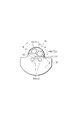
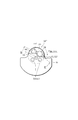
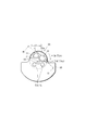
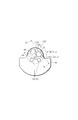
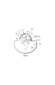
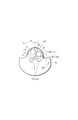
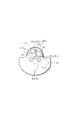
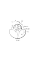
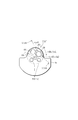
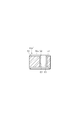
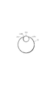
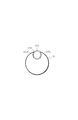
- FIG. 3A shows a plan view of the eccentric bush 36 as seen from the rotation axis direction.
- a balance hole 44 is formed in the eccentric bush 36.
- the eccentric bush 36 has rivet holes 48 and 48 for fixing the counterweight 46, and the counterweight 46 also has rivet holes 50 and 50 at positions facing the rivet holes 48 and 48. Has been.
- the counterweight 46 is fixed to the eccentric bush 36 by inserting the rivet 52 into the rivet holes 48 and 48 and the rivet holes 50 and 50.
- the counterweight 46 cancels the centrifugal force acting on the rotary shaft 20 as the movable scroll 10 turns.
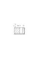
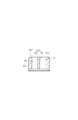
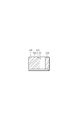
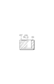
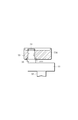
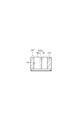
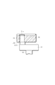
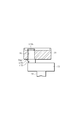
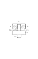
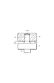
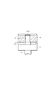
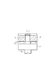
- FIG. 3B shows a cross-sectional view taken along the line II of FIG. 3A, the grooves (introduction passages) 54, 55 are formed on the bottom surface (end surface) 36a of the eccentric bush 36 so as to face each other with the crank pin hole 38 therebetween. Is formed.
- the grooves 54 and 55 have substantially the same angle between the straight line extending from the rotation axis center P and passing through the axis of the crankpin hole 38 and the straight line along the side walls 54a and 55a of the groove parts 54 and 55, respectively. It is formed to be a right angle.
- the opposed grooves 54 and 55 are formed to extend to the outer peripheral edge of the eccentric bush 36 so as to sandwich the axis of the crankpin hole 38, respectively. ing. That is, since the groove portions 54 and 55 are formed in the rotation direction of the eccentric bush 36, when the rotary shaft 20 is driven to rotate the eccentric bush 36, the lubricating oil can be easily introduced from the end portion of the groove portion 54. .
- the movable scroll 10 includes an end plate 10a, and a movable spiral body 58 extending toward the end plate 8a of the fixed scroll 8 is integrally formed with the end plate 10a.
- the fixed spiral body 56 extending toward the end plate 10 a of the movable scroll 10 is also integrally formed on the end plate 8 a of the fixed scroll 8.
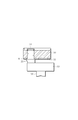
- the operation of the scroll compressor according to the present embodiment configured as described above will be described in detail with reference to a schematic view in the vicinity of the eccentric bush 36 shown in FIG.
- the crank pin 34 is fitted.
- the eccentric bush 36 is rotated. Accordingly, a turning motion is applied to the movable scroll 10 whose rotation is blocked by the thrust ball 60 that is a rotation blocking mechanism.
- a compression chamber 18 for refrigerant containing lubricating oil is defined between the spiral body 56 and the movable spiral body 58.
- the volume of the movable spiral body 58 is reduced while the movable scroll body 58 moves toward the center of the fixed spiral body 56 by the revolving motion of the movable scroll 10 with respect to the fixed scroll 8, and the refrigerant is compressed.
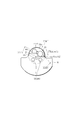
- the eccentric bush 36 rotates in the direction of the arrow shown in FIG.
- the lubricating oil is supplied to the fitting portion between the crank pin 34 and the crank pin hole 38 by forming the groove portion 54 on the bottom surface of the eccentric bush 36 on the rotating shaft 20 side. Therefore, the lubricity of the crankpin 34 can be improved and the amount of wear of the crankpin 34 can be greatly reduced. Further, even if wear powder may be generated, the wear powder is discharged from the groove portion 55, so that the stay of wear powder in the fitting portion is prevented, and further wear of the crankpin due to the accumulated wear powder is also prevented. The durability of the crankpin 34 can be improved.
- the groove portions 54 and 55 are formed in the rotational direction of the eccentric bush 36, and the rotation of the eccentric bush 36 by driving the rotary shaft 20 allows the lubricating oil to be more easily introduced into the groove 54. The durability can be further improved.
- FIG. 5 is a graph showing the amount of wear of the crankpin 34 when the crankpin 34 is fitted to the conventional eccentric bush 36 and the amount of wear of the crankpin 34 in this embodiment.
- the wear amount of the crank pin 34 is reduced to 1/30 of the wear amount of the conventional crank pin 34.
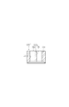
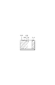
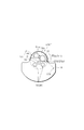
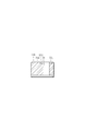
- FIG. 6A a plan view of the eccentric bush 36 ′ viewed from the rotational axis direction is shown, and in FIG. 6B, as shown in a sectional view taken along line II-II in FIG.
- 54 is formed so that the angle between the straight line extending from the rotation axis center P and passing through the axis of the crankpin hole 38 and the straight line along the side wall 54a of the groove 54 is substantially a right angle.
- a groove 55b is formed extending from the crankpin hole 38 so as to avoid the balance hole 44.
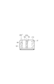
- FIG. 7A a plan view of the eccentric bush 36 ′′ as seen from the direction of the rotation axis is shown, and in FIG.
- 54 is formed so that the angle between the straight line extending from the rotation axis center P and passing through the axis of the crankpin hole 38 and the straight line along the side wall 54a of the groove 54 is substantially a right angle.
- a groove 55c is formed so that the crank pin hole 38 and the balance hole 44 communicate with each other.
- FIG. 8A shows a plan view of the eccentric bush 136 viewed from the direction of the rotation axis
- FIG. 8B shows a cross-sectional view along the line IV-IV of FIG. Are formed with grooves (introduction passages) 154 and 155 at positions facing each other with the crankpin hole 38 therebetween. As shown in FIG.
- the grooves 154 and 155 have substantially the same angle between a straight line extending from the rotation axis center P and passing through the axis of the crankpin hole 38 and a straight line along the side walls 154a and 155a of the grooves 154 and 155, respectively.
- the opposing groove portions 154 and 155 are formed to extend at right angles and extend to the outer peripheral edge portion of the eccentric bush 136 so as to sandwich the shaft center of the crankpin hole 38.
- the bottoms of the groove portions 154 and 155 are tapered so as to become deeper toward the crankpin hole 38, respectively.
- FIG. 9A a plan view of the eccentric bushing 136 ′ viewed from the direction of the rotation axis is shown, and in FIG. 9B, the groove portion is shown as a sectional view taken along the line VV in FIG. As for 154, as described above, the angle between the straight line extending from the rotation axis center P so as to pass through the axis of the crankpin hole 38 and the straight line along the side wall 154a of the groove 154 is substantially perpendicular.
- a groove portion 155b is formed extending from the crank pin hole 38 so as to avoid the balance hole 44.
- the angle between the straight line extending from the rotation axis center P so as to pass through the axis of the crankpin hole 38 and the straight line along the side wall 154a of the groove 154 is substantially perpendicular.
- a groove portion 155c is formed so as to allow the crankpin hole 38 and the balance hole 44 to communicate with each other.
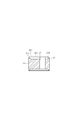
- FIG. 11A a plan view of the eccentric bush 236 viewed from the direction of the rotation axis is shown, and in FIG. 11B, a sectional view taken along the line VII-VII of FIG.
- FIG. 11B a sectional view taken along the line VII-VII of FIG.
- the chamfered portion 37 is formed by chamfering the outer peripheral edge of the bottom surface 36 a of the eccentric bush 236 including the peripheral edges of the grooves 54 and 55.
- the eccentric bush 236 supports the boss 42 of the movable scroll 10 via the drive bearing 40, and the outer peripheral surface is in contact with the drive bearing 40.
- 55 may easily cause minute irregularities on the peripheral edge of each end, and the irregularity may roughen the outer peripheral surface of the eccentric bush 236 and deteriorate the roundness.
- the outer peripheral edge of the bottom surface 36a of the eccentric bush 236 Since the chamfered portion 37 is formed in the portion, contact between the outer peripheral edge portion of the bottom surface 36 a of the eccentric bush 236 and the drive bearing 40 is avoided. That is, the roundness is ensured for the outer peripheral surface portion 39 of the eccentric bush 236 that contacts the drive bearing 40.
- FIG. 12A a plan view of the eccentric bush 236 ′ viewed from the rotational axis direction is shown, and in FIG. 12B, a sectional view taken along line VIII-VIII of FIG.
- the angle at which the straight line extending from the rotation axis center P so as to pass the axis of the crankpin hole 38 and the straight line along the side wall 54a of the groove portion 54 is substantially perpendicular.
- a groove 55b is formed extending from the crankpin hole 38 so as to avoid the balance hole 44.
- FIG. 13A shows a plan view of an eccentric bush 236 ′′ viewed from the direction of the rotation axis
- FIG. 13B shows a cross-sectional view along the line IX-IX in FIG.
- the angle at which the straight line extending from the rotation shaft center P so as to pass through the axis of the crankpin hole 38 and the straight line along the side wall 54a of the groove portion 54 is substantially perpendicular.
- a groove 55c is formed so that the crank pin hole 38 and the balance hole 44 are communicated with each other.
- FIG. 14A shows a plan view of the eccentric bush 336 as viewed from the direction of the rotation axis
- FIG. 14B shows a cross-sectional view along the line XX of FIG. 14A, as in the second embodiment.
- Grooves (introduction passages) 154 and 155 are formed on the bottom surface 36a of the eccentric bush 336 at positions facing each other with the crank pin hole 38 interposed therebetween.
- the chamfered portion 37 is formed on the outer peripheral edge of the bottom surface 36 a of the eccentric bush 336 by including the peripheral edges of the grooves 154 and 155.
- the chamfered portion 37 is formed on the outer peripheral edge portion of the bottom surface 36 a of the eccentric bush 336, so that the contact between the outer peripheral edge portion of the bottom surface 36 a of the eccentric bush 336 and the drive bearing 40 is avoided. That is, roundness is ensured for the outer peripheral surface portion 39 that contacts the drive bearing 40 in the outer peripheral surface of the eccentric bush 336.
- the lubricity of the crankpin 34 can be improved, and the durability of the crankpin 34 can be improved, while the life of the eccentric bush 336 can be prevented from being reduced.
- FIG. 15A a plan view of the eccentric bush 336 ′ viewed from the rotational axis direction is shown, and in FIG. 15B, a sectional view taken along line XI-XI in FIG.
- the angle at which the straight line extending from the rotation axis center P and passing through the axis of the crankpin hole 38 and the straight line along the side wall 154a of the groove portion 154 intersects is substantially right.
- a groove portion 155b is formed extending from the crankpin hole 38 so as to avoid the balance hole 44.
- the groove portion 154 has the eccentric bush while ensuring the roundness of the outer peripheral surface portion 39 that contacts the drive bearing 40 out of the outer peripheral surface of the eccentric bush 336 ′. Since the rotation shaft 20 is driven to rotate the eccentric bush 336 ′, the lubricating oil can be easily introduced from the end of the groove 154.
- a second modification of the fourth embodiment will be described below.
- FIG. 16A a plan view of the eccentric bush 336 ′′ viewed from the rotational axis direction is shown, and in FIG. 16B, a sectional view taken along line XII-XII of FIG.
- the angle at which the straight line extending from the rotation axis center P and passing through the axis of the crankpin hole 38 and the straight line along the side wall 154a of the groove portion 154 intersects is substantially right.
- a groove 155c is formed so that the crankpin hole 38 and the balance hole 44 communicate with each other.
- FIG. 17A shows a plan view of the eccentric bush 436 seen from the direction of the rotation axis
- FIG. 17B shows a cross-sectional view along the line XIII-XIII of FIG. Are formed with grooves (introduction passages) 254 and 255 at positions facing each other across the crankpin hole 38. As shown in FIG.
- the groove portions 254 and 255 have an angle at which a straight line extending from the rotation axis center P and passing through the axis of the crankpin hole 38 and a straight line along the side walls 254a and 255a of the groove portions 254 and 255 respectively.
- the opposed grooves 254 and 255 are formed to extend at right angles and extend to the outer peripheral edge of the eccentric bush 436 so as to sandwich the axis of the crankpin hole 38.
- the bottoms of the groove portions 254 and 255 are formed deeper and flat on the crankpin hole 38 side than the groove portions 54 and 55 of the first embodiment, and in the vicinity of the end portions of the groove portions 254 and 255, respectively. It has a tapered shape that becomes shallower. Further, the chamfered portion 37 is formed on the outer peripheral edge portion of the bottom surface 36a of the eccentric bush 436 by chamfering the peripheral edge portions of the groove portions 254 and 255 in the same manner as in the third and fourth embodiments. . Even in the case of the fifth embodiment, the groove portion 254 is formed in the rotational direction of the eccentric bush 436 while ensuring the roundness of the outer peripheral surface portion 39 of the eccentric bush 436 that contacts the drive bearing 40.
- the groove portions 254 and 255 are formed deeper and flatter than the groove portions 54 and 55 of the first embodiment, when the rotating shaft 20 is driven and the eccentric bush 436 rotates, the lubricating oil is fed from the end of the groove portion 254. Can be easily introduced, and the lubricating oil can be easily supplied to the fitting portion between the crankpin 34 and the crankpin hole 38, thereby further improving the lubricity of the crankpin 34 and improving the durability of the crankpin 34. This can be further improved.
- FIG. 18A a plan view of the eccentric bush 436 ′ viewed from the direction of the rotation axis is shown, and in FIG. 18B, the groove portion is shown as a cross-sectional view along the XIV-XIV line in FIG. 254 is formed so that an angle between a straight line extending from the rotation axis center P and passing through the axis of the crankpin hole 38 and a straight line along the side wall 254a of the groove 254 is substantially a right angle.
- a groove 255b is formed so as to avoid the balance hole 44 from 38.
- the groove portion 254 has the eccentric bush while ensuring the roundness of the outer peripheral surface portion 39 of the eccentric bush 436 ′ that contacts the drive bearing 40. Since the rotating shaft 20 is driven to rotate the eccentric bush 436 ′, the lubricating oil can be easily introduced from the end portion of the groove portion 254.
- FIG. 19A a plan view of the eccentric bush 436 ′′ viewed from the direction of the rotation axis is shown, and in FIG. 19B, the groove portion is shown.
- 254 is formed so that an angle between a straight line extending from the rotation axis center P and passing through the axis of the crankpin hole 38 and a straight line along the side wall 254a of the groove 254 is substantially a right angle.
- a groove portion 255c is formed so as to allow the 38 and the balance hole 44 to communicate with each other.
- the groove portion 254 has the eccentric bush while ensuring the roundness of the outer peripheral surface portion 39 of the eccentric bush 436 ′′ that contacts the drive bearing 40. Since the rotation shaft 20 is driven to rotate the eccentric bush 436 ′′, the lubricating oil can be easily introduced from the end portion of the groove portion 254.
- FIG. 20A shows a plan view of the eccentric bush 536 viewed from the direction of the rotation axis
- FIG. 20B shows a cross-sectional view along the line XVI-XVI of FIG.
- the notches 354 and 355 are formed by straight lines extending from the rotation axis center P so as to pass the axis of the crankpin hole 38 and straight lines along the side walls 354a and 355a of the notches 354 and 355, respectively.
- the intersecting angles are formed so as to be substantially right angles, and the notches 354 and 355 facing each other are formed so as to sandwich the axis of the crankpin hole 38.
- the opening ends of the notches 354 and 355 are the end portions of the abutting portion 35 of the crank pin 34. And a predetermined length away from the end of the abutting portion 35 so that a gap with a predetermined length is formed.
- the refrigerant containing the lubricating oil introduced into the notch 354 enters the gap between the crankpin 34 and the crankpin hole 38 as shown by the arrow in FIG. Lubricating oil is supplied to the fitting portion.
- Lubricating oil is supplied to the fitting portion.
- abrasion powder is generated by the crank pin 34 being in sliding contact with the crank pin hole 38, it is discharged to the outside through the notch portion 355 as indicated by broken line arrows in FIG.
- FIG. 22A shows a plan view of the eccentric bushing 536 ′ viewed from the direction of the rotation axis
- FIG. 22B shows a cutaway view along the XVII-XVII line in FIG. 22A.
- the portion 354 is formed so that the angle between the straight line extending from the rotation axis center P and passing through the axis of the crankpin hole 38 and the straight line along the side wall 354a of the notch 354 is substantially a right angle.
- a notch 355b is formed extending from the crankpin hole 38 so as to avoid the balance hole 44.
- FIG. 23A shows a plan view of the eccentric bushing 536 ′′ viewed from the direction of the rotation axis
- FIG. 23B shows a cross-sectional view taken along the line XVIII-XVIII of FIG.
- the portion 354 is formed so that the angle between the straight line extending from the rotation axis center P and passing through the axis of the crankpin hole 38 and the straight line along the side wall 354a of the notch 354 is substantially a right angle.
- a notch 355c is formed so as to allow the crankpin hole 38 and the balance hole 44 to communicate with each other.
- FIG. 24A shows a plan view of the eccentric bush 636 viewed from the rotational axis direction
- FIG. 24B shows a cross-sectional view along the line XIX-XIX in FIG.
- notches 454 and 455 which are notched obliquely from the outer peripheral edge of the bottom surface 36a toward the crankpin hole 38 at positions facing each other across the crankpin hole 38 of the eccentric bush 636.
- the notches 454 and 455 are formed by straight lines extending from the rotation axis center P so as to pass the axis of the crankpin hole 38 and straight lines along the side walls 454a and 455a of the notches 454 and 455, respectively.
- the intersecting angles are formed so as to be substantially a right angle, and the notches 454 and 455 facing each other are formed so as to sandwich the axis of the crankpin hole 38.
- FIG. 25A shows a plan view of the eccentric bush 636 ′ viewed from the direction of the rotation axis
- FIG. 25B shows a cross-sectional view along the line XX-XX in FIG.
- the portion 454 is formed such that the angle between the straight line extending from the rotation axis center P and passing through the axis of the crankpin hole 38 and the straight line along the side wall 454a of the notch 454 is substantially a right angle.
- a notch 455b is formed extending from the crankpin hole 38 so as to avoid the balance hole 44.
- FIG. 26A shows a plan view of the eccentric bush 636 ′′ viewed from the direction of the rotation axis
- FIG. 26B shows a cross-sectional view taken along the line XXI-XXI of FIG.
- the portion 454 is formed such that the angle between the straight line extending from the rotation axis center P and passing through the axis of the crankpin hole 38 and the straight line along the side wall 454a of the notch 454 is substantially a right angle.
- a notch 455c is formed so that the crankpin hole 38 and the balance hole 44 communicate with each other.
- FIG. 27A shows a plan view of the eccentric bush 736 viewed from the direction of the rotation axis
- FIG. 27B shows a cross-sectional view along the line XXII-XXII of FIG.
- notches 554 and 555 are formed with notches (introduction passages) 554 and 555 that are notched straight toward the crankpin hole 38 at positions facing each other across the crankpin hole 38 from a predetermined position on the bottom surface 36a of the eccentric bush 536, respectively.
- the notches 554 and 555 are arranged so that the angle between the straight line extending from the rotation axis center P so as to pass the axis of the crankpin hole 38 and the straight line along the side walls 554a and 555a of the notches 554 and 555 is substantially a right angle.
- the formed and opposed notches 554 and 555 are formed so as to sandwich the axis of the crankpin hole 38.
- the opening ends of the notches 554 and 555 are the end portions of the abutting portion 35 of the crank pin 34. And a predetermined length away from the end of the abutting portion 35 so as to form a gap having a predetermined width.
- FIG. 29A shows a plan view of the eccentric bush 736 ′ viewed from the rotational axis direction
- FIG. 29B shows a cross-sectional view along the line XXIII-XXIII in FIG. 29A.
- the portion 554 is formed so that the angle between the straight line extending from the rotation axis center P and passing through the axis of the crankpin hole 38 and the straight line along the side wall 554a of the notch 554 is substantially a right angle.
- a notch 555b is formed extending from the crankpin hole 38 so as to avoid the balance hole 44.
- FIG. 30A shows a plan view of the eccentric bush 736 ′′ viewed from the direction of the rotation axis
- FIG. 30B shows a cross-sectional view along the line XXIV-XXIV in FIG. 30A.
- the portion 554 is formed so that the angle between the straight line extending from the rotation axis center P and passing through the axis of the crankpin hole 38 and the straight line along the side wall 554a of the notch 554 is substantially a right angle.
- a notch 555c is formed so that the crankpin hole 38 and the balance hole 44 communicate with each other.
- FIG. 31A is a plan view of the eccentric bush 836 viewed from the direction of the rotation axis
- FIG. 31B is a cross-sectional view taken along line XXV-XXV in FIG.
- the crank pin hole 38 is formed with a vertical groove portion 62 extending along the inner surface of the crank pin hole 38 from the groove portion 54 formed on the bottom surface 36 a of the eccentric bush 36.
- FIG. 32A a plan view of the eccentric bush 836 ′ viewed from the direction of the rotation axis is shown, and as shown in FIG. 32B, a cross-sectional view along the line XXVI-XXVI in FIG.
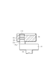
- FIG. 33A shows an enlarged view of the eccentric bush 36 constituting the scroll compressor 1
- FIG. 33B shows a plan view of the rotary shaft 20 of FIG. 33A viewed from the crank pin 34 side, according to the tenth embodiment.
- the abutting portion 135 of the crank pin 134 is formed by notching the end portion side of the large-diameter shaft portion 22 of the rotating shaft 20 in the direction of the rotating shaft 20. That is, the abutting portion 135 has a cutout portion 135a in which a portion corresponding to the outer peripheral edge side of the large-diameter shaft portion 22 is partially cut out.
- the abutting portion 135 viewed from the crank pin 134 side is substantially D. It has a shape.
- the lubricating oil is supplied from the notch 135a of the abutting portion 135 to the fitting portion of the crank pin 134 and the crank pin hole 38, so that the same effect as in the first embodiment is obtained. be able to. Even if abrasion powder is generated from the crankpin 134, the abutment portion 135 is made substantially D-shaped, so that a lubricating oil introduction passage is secured, and the same effect as in the first embodiment is obtained. be able to.
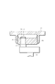
- 34A shows a schematic view of the vicinity of the eccentric bush 36
- FIG. 34B shows a plan view of the rotary shaft 20 of FIG. 34A viewed from the crank pin 134a side.
- the crank pin 134a is formed by cutting out the outer peripheral surface in the direction of the rotary shaft 20 together with the notch portion 135b of the abutting portion 135.
- the crank pin 134a and the notch 35b formed in this way have a substantially D shape when viewed from the crank pin 134a side.
- the crank pin 134a and the crank pin hole 38 form a lubricating oil passage (introduction passage).
- FIG. 35A shows a schematic view of the vicinity of the eccentric bush 36
- FIG. 35B shows a plan view of the rotary shaft 20 of FIG. 35A viewed from the crank pin 134b side.
- the crank pin 134b is formed by cutting out the outer peripheral surface in the direction of the rotating shaft 20, and the surface on the eccentric bush 36 side of the abutting portion 135 is radially outward from the notched outer peripheral surface of the crank pin 134b.
- a notch portion 135c is formed by making the facing surface lower than the other surface by a predetermined length.
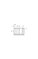
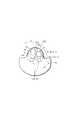
- FIG. 36B shows a plan view of the rotary shaft 20 of FIG. 36A viewed from the crank pin 34 side, according to the thirteenth embodiment.
- the abutting portion 235 of the crank pin 234 is formed with two faces that are notched in parallel with the direction of the rotary shaft 20 and face each other. That is, the abutting portion 235 has a pair of cutout portions 235a and 235a that are partially cutout.
- crank pin 234 When the crank pin 234 is fitted into the crank pin hole 38, the abutting portion 235 and the fitting portion of the crank pin 234 and the crank pin hole 38 are not closed by the notches 235a and 235a, thereby forming an open passage structure (introduction) Passage), lubricating oil is introduced into the fitting portion and supplied.
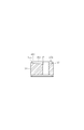
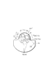
- FIG. 37A shows an enlarged view of the eccentric bush 36 constituting the scroll compressor 1
- FIG. 37B shows a plan view of the rotary shaft 20 of FIG. 37A viewed from the crank pin 34 side, according to the fourteenth embodiment.
- the crank pin 234a is formed with two pairs of notches 235b and 235b of the abutting portion 235, which are notched in parallel to the direction of the rotary shaft 20 and opposed to each other.
- the crank pin 234a is fitted into the crank pin hole 38, the crank pin 234a and the crank pin hole 38 form a lubricating oil passage (introduction passage).
- the passage formed by the fitting portion between the crank pin 234a and the crank pin hole 38 and the notch portion 235b is an open passage structure without closing the notch portion 235b side of the abutting portion 235. It becomes. Thereby, the same effect as that of the eleventh embodiment can be obtained.
- FIG. 38A shows an enlarged view of the eccentric bush 36 constituting the scroll compressor 1
- FIG. 38B shows a plan view of the rotary shaft 20 of FIG. 38A viewed from the crank pin 34 side, according to the fifteenth embodiment.
- crank pin 234b is formed with a pair of cutout portions 235c and 235c on the surface of the abutting portion 235 on the side of the eccentric bush 36, which is cut lower by a predetermined length than the other surfaces.
- crank pin 234c is formed with two opposite faces that are cut in parallel to the direction of the rotating shaft 20, and the outer peripheral face of the abutting portion 235 on the side of the eccentric bush 36 is cut off on each outer peripheral face of the crank pin 234c.
- a notch portion 235d is formed by cutting the surface facing radially outward from the other surface by a predetermined length to be lower than the other surfaces.
- a lubricating oil passage (introduction passage) is formed in the crank pin hole 38, and further the eccentric bush 36.
- An introduction passage connected to the above-described lubricating oil passage is formed between the bottom surface 36a and the notch portion 235d, so that the lubricating oil passage is not closed by the abutting portion 235 and an open passage structure is formed.
- the lubricating oil is sufficiently introduced from the introduction passage and supplied to the lubricating oil passage, and the same effect as in the twelfth embodiment can be obtained.
- FIG. 40A shows an enlarged view of the eccentric bush 36 constituting the scroll compressor 1
- FIG. 40B shows a plan view of the rotary shaft 20 of FIG. 40A viewed from the crank pin 34 side, according to the seventeenth embodiment.
- a pair of vertical groove portions 235e and 235e extending in the direction of the rotary shaft 20 are formed in the abutting portion 235 of the crank pin 234d.
- a lubricating oil passage (introduction passage) is formed in the crank pin hole 38, and further, the eccentric bush 36.
- an introduction passage connected to the above-described lubricating oil passage is formed, so that the lubricating oil passage is not blocked by the abutting portion 235, and an open passage structure is formed.
- the lubricating oil is sufficiently introduced from the introduction passage and supplied to the lubricating oil passage, and the same effect as in the tenth embodiment can be obtained.
- FIG. 41A shows an enlarged view of the eccentric bush 36 constituting the scroll compressor 1
- FIG. 41B shows a plan view of the rotary shaft 20 of FIG. 41A viewed from the crank pin 34 side, according to the eighteenth embodiment.
- a pair of vertical groove portions 235 f and 235 f extending from the eccentric bush 36 by cutting a predetermined length in the direction of the rotation shaft 20 are formed in the abutting portion 235 of the crank pin 234 e.
- a lubricating oil passage (introduction passage) is formed in the crank pin hole 38, and further, the eccentric bush 36.
- an introduction passage connected to the above-described lubricating oil passage is formed, so that the lubricating oil passage is not blocked by the abutting portion 235 and an open passage structure is formed.
- the lubricating oil is sufficiently introduced from the introduction passage and supplied to the lubricating oil passage, and the same effect as that of the seventeenth embodiment can be obtained.
- FIG. 42A shows a schematic view of the vicinity of the eccentric bush 36
- FIG. 42B shows a plan view of the rotary shaft 20 of FIG. 42A viewed from the crank pin 234f side.
- the crank pin 234f is formed with two faces that are notched in parallel with the direction of the rotation shaft 20 and opposed to each other, and the abutting portion 235 extends in the direction of the rotation shaft 20 from each outer peripheral surface of the crank pin 234f that is notched.
- a pair of vertical groove portions 235g and 235g are formed.
- FIG. 43A shows a schematic view of the vicinity of the eccentric bush 36
- FIG. 43B shows a plan view of the rotary shaft 20 of FIG. 43A viewed from the crank pin 234g side.
- the crank pin 234g is formed with two faces that are notched in parallel with the direction of the rotary shaft 20 and opposed to each other. A pair of vertical groove portions 235h and 235h extending by cutting out the length are formed.
- a lubricating oil passage (introduction passage) is formed in the crank pin hole 38, and further the eccentric bush 36 Between the bottom surface 36a and the vertical groove portion 235h, an introduction passage connected to the above-described lubricating oil passage is formed, so that the lubricating oil passage is not closed by the abutting portion 235, and an open passage structure is formed. Thereby, the lubricating oil is sufficiently introduced from the introduction passage and supplied to the lubricating oil passage, and the same effect as that of the nineteenth embodiment can be obtained.
- the present invention is not limited to the above-described embodiment.
- various introduction passages for introducing lubricating oil into the fitting portions of the crank pin and the crank pin hole have been described.
- the introduction passage is formed, the shape is It is not limited to these.
- the compressor 1 shown in each said Example is not restricted to a vertical installation type, It is good also as a horizontal installation type.
Landscapes
- Engineering & Computer Science (AREA)
- Mechanical Engineering (AREA)
- General Engineering & Computer Science (AREA)
- Rotary Pumps (AREA)
Abstract
L'invention concerne un compresseur à volute qui comprend : un arbre rotatif (20) supporté de façon rotative par un carter ; un maneton de vilebrequin (34) qui est formé de façon excentrique et solidairement sur le côté d'extrémité supérieure de l'arbre rotatif ; et un coussinet excentrique (36) monté sur le maneton de vilebrequin et qui imprime un mouvement orbital à une volute mobile lorsque l'arbre rotatif tourne. Le coussinet excentrique comprend : un alésage de maneton de vilebrequin (38) dans lequel le maneton de vilebrequin est logé et ajusté ; et des trajets d'introduction (54, 55) formés dans la surface terminale (36a) qui se trouve sur le côté de l'arbre rotatif, dans des positions qui se font face dans le plan de l'alésage du maneton de vilebrequin, les trajets d'introduction (54, 55) introduisant une huile lubrifiante dans la section d'ajustement dans laquelle le maneton de vilebrequin et l'alésage de maneton de vilebrequin sont ajustés l'un à l'autre.
Priority Applications (1)
| Application Number | Priority Date | Filing Date | Title |
|---|---|---|---|
| JP2013518103A JP6037174B2 (ja) | 2011-05-30 | 2012-05-29 | スクロール型圧縮機 |
Applications Claiming Priority (2)
| Application Number | Priority Date | Filing Date | Title |
|---|---|---|---|
| JP2011120132 | 2011-05-30 | ||
| JP2011-120132 | 2011-05-30 |
Publications (1)
| Publication Number | Publication Date |
|---|---|
| WO2012165431A1 true WO2012165431A1 (fr) | 2012-12-06 |
Family
ID=47259285
Family Applications (1)
| Application Number | Title | Priority Date | Filing Date |
|---|---|---|---|
| PCT/JP2012/063769 Ceased WO2012165431A1 (fr) | 2011-05-30 | 2012-05-29 | Compresseur à volute |
Country Status (2)
| Country | Link |
|---|---|
| JP (1) | JP6037174B2 (fr) |
| WO (1) | WO2012165431A1 (fr) |
Cited By (3)
| Publication number | Priority date | Publication date | Assignee | Title |
|---|---|---|---|---|
| CN103671107A (zh) * | 2013-12-25 | 2014-03-26 | 江苏晨宇车业有限公司 | 新型汽车空调用涡旋压缩机及其制造方法 |
| CN116507807A (zh) * | 2020-11-24 | 2023-07-28 | 三电株式会社 | 涡旋式流体机械 |
| WO2024116464A1 (fr) * | 2022-11-29 | 2024-06-06 | 株式会社豊田自動織機 | Compresseur à spirale |
Citations (6)
| Publication number | Priority date | Publication date | Assignee | Title |
|---|---|---|---|---|
| JPH0382888U (fr) * | 1989-12-11 | 1991-08-23 | ||
| JPH08319981A (ja) * | 1995-03-17 | 1996-12-03 | Nippondenso Co Ltd | スクロール型圧縮機 |
| JPH11117877A (ja) * | 1997-10-17 | 1999-04-27 | Sanden Corp | スクロール型圧縮機 |
| JP2000130364A (ja) * | 1998-10-27 | 2000-05-12 | Daikin Ind Ltd | スクロール形流体機械 |
| JP2002161879A (ja) * | 2000-11-30 | 2002-06-07 | Toyota Industries Corp | スクロール型圧縮機 |
| JP2002174189A (ja) * | 2000-09-27 | 2002-06-21 | Denso Corp | スクロール型圧縮機 |
-
2012
- 2012-05-29 JP JP2013518103A patent/JP6037174B2/ja active Active
- 2012-05-29 WO PCT/JP2012/063769 patent/WO2012165431A1/fr not_active Ceased
Patent Citations (6)
| Publication number | Priority date | Publication date | Assignee | Title |
|---|---|---|---|---|
| JPH0382888U (fr) * | 1989-12-11 | 1991-08-23 | ||
| JPH08319981A (ja) * | 1995-03-17 | 1996-12-03 | Nippondenso Co Ltd | スクロール型圧縮機 |
| JPH11117877A (ja) * | 1997-10-17 | 1999-04-27 | Sanden Corp | スクロール型圧縮機 |
| JP2000130364A (ja) * | 1998-10-27 | 2000-05-12 | Daikin Ind Ltd | スクロール形流体機械 |
| JP2002174189A (ja) * | 2000-09-27 | 2002-06-21 | Denso Corp | スクロール型圧縮機 |
| JP2002161879A (ja) * | 2000-11-30 | 2002-06-07 | Toyota Industries Corp | スクロール型圧縮機 |
Cited By (4)
| Publication number | Priority date | Publication date | Assignee | Title |
|---|---|---|---|---|
| CN103671107A (zh) * | 2013-12-25 | 2014-03-26 | 江苏晨宇车业有限公司 | 新型汽车空调用涡旋压缩机及其制造方法 |
| CN116507807A (zh) * | 2020-11-24 | 2023-07-28 | 三电株式会社 | 涡旋式流体机械 |
| CN116507807B (zh) * | 2020-11-24 | 2025-08-29 | 三电株式会社 | 涡旋式流体机械 |
| WO2024116464A1 (fr) * | 2022-11-29 | 2024-06-06 | 株式会社豊田自動織機 | Compresseur à spirale |
Also Published As
| Publication number | Publication date |
|---|---|
| JPWO2012165431A1 (ja) | 2015-02-23 |
| JP6037174B2 (ja) | 2016-11-30 |
Similar Documents
| Publication | Publication Date | Title |
|---|---|---|
| JP5701230B2 (ja) | スクロール圧縮機 | |
| KR101484728B1 (ko) | 스크롤 압축기 | |
| JP6037174B2 (ja) | スクロール型圧縮機 | |
| JP2010196663A (ja) | 圧縮機 | |
| EP2466068A1 (fr) | Machine de fluide en spirale | |
| JP6927279B2 (ja) | 圧縮機 | |
| KR102191126B1 (ko) | 전동식 압축기 | |
| JP7075407B2 (ja) | スクロール型圧縮機 | |
| JP2016156310A (ja) | 開放型圧縮機 | |
| KR102454720B1 (ko) | 스크롤 압축기 | |
| WO2018012411A1 (fr) | Compresseur de fluide frigorigène de type ouvert | |
| CN106050656B (zh) | 涡旋型流体设备 | |
| AU2005207221B2 (en) | Swing compressor | |
| JP2004316537A (ja) | 流体圧縮機 | |
| JP2011174453A (ja) | スクロール圧縮機 | |
| WO2015049745A1 (fr) | Compresseur à spirale | |
| JP3949840B2 (ja) | スクロール流体機械 | |
| JP5341819B2 (ja) | スクロール型流体機械 | |
| JP2021025459A (ja) | スクロール圧縮機 | |
| JP5058919B2 (ja) | スクロール型流体機械 | |
| KR100234769B1 (ko) | 스크롤 압축기의 오일토출량 저감 및 윤활구조 | |
| KR20100058826A (ko) | 오일분리구조를 가진 스크롤 압축기 | |
| JP2020033909A (ja) | スクロール圧縮機 | |
| CN110268164A (zh) | 旋转式压缩机 | |
| WO2018030065A1 (fr) | Machine à fluide de type à volute |
Legal Events
| Date | Code | Title | Description |
|---|---|---|---|
| 121 | Ep: the epo has been informed by wipo that ep was designated in this application |
Ref document number: 12793065 Country of ref document: EP Kind code of ref document: A1 |
|
| ENP | Entry into the national phase |
Ref document number: 2013518103 Country of ref document: JP Kind code of ref document: A |
|
| NENP | Non-entry into the national phase |
Ref country code: DE |
|
| 122 | Ep: pct application non-entry in european phase |
Ref document number: 12793065 Country of ref document: EP Kind code of ref document: A1 |