WO2012165490A1 - Dispositif de filtration - Google Patents
Dispositif de filtration Download PDFInfo
- Publication number
- WO2012165490A1 WO2012165490A1 PCT/JP2012/063961 JP2012063961W WO2012165490A1 WO 2012165490 A1 WO2012165490 A1 WO 2012165490A1 JP 2012063961 W JP2012063961 W JP 2012063961W WO 2012165490 A1 WO2012165490 A1 WO 2012165490A1
- Authority
- WO
- WIPO (PCT)
- Prior art keywords
- raw water
- purified water
- filter
- water
- passage
- Prior art date
- Legal status (The legal status is an assumption and is not a legal conclusion. Google has not performed a legal analysis and makes no representation as to the accuracy of the status listed.)
- Ceased
Links
Images





Classifications
-
- B—PERFORMING OPERATIONS; TRANSPORTING
- B01—PHYSICAL OR CHEMICAL PROCESSES OR APPARATUS IN GENERAL
- B01D—SEPARATION
- B01D29/00—Filters with filtering elements stationary during filtration, e.g. pressure or suction filters, not covered by groups B01D24/00 - B01D27/00; Filtering elements therefor
- B01D29/62—Regenerating the filter material in the filter
- B01D29/66—Regenerating the filter material in the filter by flushing, e.g. counter-current air-bumps
- B01D29/668—Regenerating the filter material in the filter by flushing, e.g. counter-current air-bumps with valves, e.g. rotating valves for coaxially placed filtering elements
-
- B—PERFORMING OPERATIONS; TRANSPORTING
- B01—PHYSICAL OR CHEMICAL PROCESSES OR APPARATUS IN GENERAL
- B01D—SEPARATION
- B01D29/00—Filters with filtering elements stationary during filtration, e.g. pressure or suction filters, not covered by groups B01D24/00 - B01D27/00; Filtering elements therefor
- B01D29/50—Filters with filtering elements stationary during filtration, e.g. pressure or suction filters, not covered by groups B01D24/00 - B01D27/00; Filtering elements therefor with multiple filtering elements, characterised by their mutual disposition
- B01D29/52—Filters with filtering elements stationary during filtration, e.g. pressure or suction filters, not covered by groups B01D24/00 - B01D27/00; Filtering elements therefor with multiple filtering elements, characterised by their mutual disposition in parallel connection
-
- B—PERFORMING OPERATIONS; TRANSPORTING
- B01—PHYSICAL OR CHEMICAL PROCESSES OR APPARATUS IN GENERAL
- B01D—SEPARATION
- B01D29/00—Filters with filtering elements stationary during filtration, e.g. pressure or suction filters, not covered by groups B01D24/00 - B01D27/00; Filtering elements therefor
- B01D29/60—Filters with filtering elements stationary during filtration, e.g. pressure or suction filters, not covered by groups B01D24/00 - B01D27/00; Filtering elements therefor integrally combined with devices for controlling the filtration
-
- C—CHEMISTRY; METALLURGY
- C02—TREATMENT OF WATER, WASTE WATER, SEWAGE, OR SLUDGE
- C02F—TREATMENT OF WATER, WASTE WATER, SEWAGE, OR SLUDGE
- C02F1/00—Treatment of water, waste water, or sewage
- C02F1/001—Processes for the treatment of water whereby the filtration technique is of importance
-
- C—CHEMISTRY; METALLURGY
- C02—TREATMENT OF WATER, WASTE WATER, SEWAGE, OR SLUDGE
- C02F—TREATMENT OF WATER, WASTE WATER, SEWAGE, OR SLUDGE
- C02F2201/00—Apparatus for treatment of water, waste water or sewage
- C02F2201/002—Construction details of the apparatus
- C02F2201/005—Valves
-
- C—CHEMISTRY; METALLURGY
- C02—TREATMENT OF WATER, WASTE WATER, SEWAGE, OR SLUDGE
- C02F—TREATMENT OF WATER, WASTE WATER, SEWAGE, OR SLUDGE
- C02F2201/00—Apparatus for treatment of water, waste water or sewage
- C02F2201/002—Construction details of the apparatus
- C02F2201/007—Modular design
-
- C—CHEMISTRY; METALLURGY
- C02—TREATMENT OF WATER, WASTE WATER, SEWAGE, OR SLUDGE
- C02F—TREATMENT OF WATER, WASTE WATER, SEWAGE, OR SLUDGE
- C02F2303/00—Specific treatment goals
- C02F2303/16—Regeneration of sorbents, filters
Definitions
- the present invention relates to a filtration device that is provided with a plurality of filters and filters raw water with these to make purified water.
- filtration devices equipped with a filter for filtering raw water to obtain purified water have been widely used.
- the filtering ability is reduced by trapped impurities (for example, inorganic particles).
- some filtration devices are known that can remove impurities (backwash) by allowing purified water obtained by filtration through a filter to flow backward through the filter.
- this backwashing method there is a method of storing a part of the purified water in a tank and backflowing the purified water to the filter during backwashing, but this requires equipment such as a tank as a whole. Invite larger size. Therefore, in order not to require a large facility, two filters are provided in parallel, and the water flow is switched by a switching valve so that a part of the purified water from one filter can flow back to the other filter.
- a method of switching has been proposed (for example, Patent Documents 1 and 2).
- This invention is made
- the objective is to provide the filtration apparatus which enables the backwashing of the filter by purified water by simple operation in the filtration apparatus provided with two or more filters. is there.
- a filtration device includes a raw water inlet, first and second raw water passages, first and second purified water passages, a purified water outlet, and a wastewater flow.
- An outlet is formed on the outer wall surface, a water flow switching device main body into which raw water flows into the raw water flow inlet, and a valve body fitted in a rotatable manner in a hollow hole formed in the water flow switching device main body, A first flow filter having a first raw water pipe and a first purified water pipe connected to the first raw water passage opening and the first purified water passage opening, respectively, A second filter having a second raw water pipe and a second water purification pipe connected to the two raw water passage openings and the second purified water passage opening, respectively, and the valve body is in a rotating position in the water purification mode.
- the raw water inlet is in communication with the first and second raw water passages, and the first and second purified water passages are By communicating with the outlet, the raw water is filtered by the first and second filters, the generated purified water flows out from the purified water outlet, and the valve body is in the first backwash mode.
- the raw water inlet communicates with the second raw water passage
- the drainage outlet communicates with the first raw water passage
- the first and second purified water passages are the By blocking communication to the purified water outlet
- the raw water is filtered by the second filter, the generated purified water flows backward through the first filter, and the waste water is discharged from the drain outlet.
- the raw water inlet communicates with the first raw water passage
- the drainage outlet communicates with the second raw water passage
- the first and second purified water passage ports are blocked from communicating with the purified water outlet. Therefore, the raw water is filtered by the first filter, is generated purified water drained back through the second filter is equal to or discharged from the water discharge outlet.
- the filtration device includes a first filter group including a plurality of filters instead of the first filter, and a second filter group including a plurality of filters instead of the second filter. It can also be provided.
- a purified water mode in which purified water flows out to the outside and a first backwash mode in which purified water is allowed to flow backward through the first filter or the first filter group and the filter medium is washed.
- a second backwash mode in which purified water is allowed to flow back through the second filter or the second filter group to wash the filter medium, and the backwashing of the filter by purified water can be performed with a simple operation. It becomes possible.
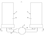
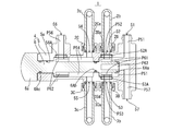
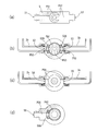
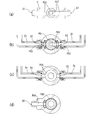
- FIG. 1 It is a top view which shows the external appearance of the filtration apparatus which concerns on embodiment of this invention. It is a left view which shows the external appearance of a filtration apparatus same as the above. It is a top view sectional view at the time of the water purification mode of a filter apparatus same as the above, Comprising: It is a thing in the cut surface shown by HH. It is a figure which shows the lower part of the left side surface cross section at the time of the water purification mode of a filtration apparatus same as the above, (a) is a cut surface shown by AA, (b) is a cut surface shown by BB, (c) Is a cut surface indicated by CC, and (d) is a cut surface indicated by DD.
- FIG. 3 is a cross-sectional view in plan view of the filtration device according to the first embodiment in a first backwash mode, taken along a cut surface indicated by HH. It is a figure which shows the lower part of the cross section of the left side view at the time of the 1st backwash mode of a filtration apparatus same as the above, (a) is the cut surface shown by AA, (b) is the cut surface shown by BB. , (C) is a cut surface indicated by CC, and (d) is a cut surface indicated by DD.
- FIG. 5 is a cross-sectional view in plan view of the above filtration device in the second backwash mode, taken along a cut surface indicated by HH.
- the filtration device 1 includes a first filter 2, a second filter 3, and a water flow switch 4 to which they are connected, By the switching operation of the water flow switch 4, the raw water is filtered, the first filter 2 is backwashed, and the second filter 3 is backwashed.
- the first filter 2 has a first filter body 2a in which a filter medium is provided, and has a first raw water pipe 2b and a first water purification pipe 2c on the side where the water flow switching device 4 is located. is doing.
- the 2nd filter 3 also has the 2nd filter main body 3a with which the filter medium was provided in the inside, and the 2nd raw
- the filter medium is not particularly limited, but may be a hollow fiber membrane, a flat membrane, a ceramic membrane, an activated carbon molded filter, a laminated filter, a bobbin filter, a metal filter, or the like.
- the water flow switching device 4 has a water flow switching device main body 5 and a valve body 6 fitted in a stepped hollow hole 5a formed in the water flow switching device 5 in a rotatable state. These are formed into a substantially cylindrical shape. Several water channels are isolated from each other inside the water flow switch 4. In order to prevent water leakage between the water channels, rubber packing materials (O-rings) 2Ba, 2Ca, 3Ba, 3Ca, 52A, 53A, 56A, 6Aa, 6Ab, and 6Ac are provided at appropriate places.
- the water flow switching device body 5 includes a raw water inlet 51, a first raw water passage 52, a second raw water passage 53, a first purified water passage 54, a second purified water passage 55, a purified water outlet 56, and drainage.
- An outflow port 57 is formed on the outer wall surface, and each water channel described later is formed so that the hollow hole 5a communicates with the outside through each of the ports 51, 52, 53, 54, 55, 56, 57. ing.
- Raw water flows into the raw water inlet 51.
- the first raw water pipe 2b and the first purified water pipe 2c of the first filter 2 are connected to the first raw water passage port 52 and the first purified water passage port 54 by means of connectors 2B and 2C, respectively.
- the second raw water pipe 3b and the second purified water pipe 3c of the second filter 3 are connected to the second raw water passage port 53 and the second purified water passage port 55 by connectors 3B and 3C, respectively. .
- the raw water inlet 51 and the drain outlet 57 are in the vicinity of one end of the water flow switch main body 5 (opposite side of an operation gripping portion 6a, which will be described later of the valve body 6 in plan view). Are formed so as to face each other in a portion protruding slightly outward.
- a first raw water passage port 52 and a second raw water passage port 53 are located on the side of the outer wall surface on the other end side (on the side of an operation gripping portion 6a to be described later of the valve body 6 in plan view). Are formed to face each other.
- the 1st purified water passage port 54 and the 2nd purified water passage port 55 are formed in the other edge part side rather than them so that it may mutually face in the part of the side surface of an outer wall surface. Further, a purified water outlet 56 is formed on the side of the outer wall surface on the other end side so as to protrude slightly outward.
- each water channel provided in the water flow switching device main body 5 includes a raw water inflow passage P51 that communicates with the raw water inlet 51, a first raw water passage P52 that communicates with the first raw water passage 52, and a second raw water passage.
- a raw water inflow passage P51 that communicates with the raw water inlet 51
- a first raw water passage P52 that communicates with the first raw water passage 52
- a second raw water passage To the second raw water passage P53 leading to the mouth 53, the purified water passage P54 leading to the first purified water passage 54 and the second purified water passage 55, the purified water outlet P56 leading to the purified water outlet 56, and the drain outlet 57 It is the drainage outflow path P57 which leads.
- the raw water inflow passage P51 and the drainage outflow passage P57 respectively extend from the raw water inflow port 51 or the drainage outflow port 57 so as to be substantially orthogonal to the central axis of the water flow switching device 4.
- the drainage outflow passage P57 extends to the central axis (see FIG. 4A, etc.), bends to the other end side with a circular hole coaxial with the central axis, and beyond that, the valve body 6 will be described later.
- To the third flow path P63 see FIG. 3 and the like.
- the raw water inflow channel P51 is expanded in the circumferential direction so as to sandwich the drainage outflow channel P57 in the vicinity of the central axis (see FIG. 4A), and the other end is surrounded by surrounding the circular hole of the drainage outflow channel P57. It bends to the part side and leads to a first flow path P61 (described later) of the valve body 6 (see FIG. 3 and the like).
- each of the first raw water passage P52 and the second raw water passage P53 extends from the first raw water passage 52 or the second raw water passage 53 so as to be substantially orthogonal to the central axis.
- natural water passageway P53 are the 1st flow paths which the valve body 6 mentions later according to the rotation position of the valve body 6 via the rubber packing materials 52A and 53A, respectively. It leads to either P61 or the third flow path P63 (see FIG. 4B, etc.).
- the purified water passage P54 extends from the first purified water passage 54 and the second purified water passage 55 so as to be substantially orthogonal to the central axis, and is extended and connected in the circumferential direction in the vicinity of the central axis ( (Refer FIG.4 (c) etc.).
- the purified water passage P54 bends to the other end side while enclosing the valve body 6 and communicates with a second flow path P62 described later of the valve body 6 (see FIG. 3 and the like).
- the purified water outflow passage P56 extends from the purified water outlet 56 so as to be substantially orthogonal to the central axis, and the valve body 6 will be described later according to the rotational position of the valve body 6 via the rubber packing material 56A. To or from the second flow path P62 (see FIG. 4D, etc.).
- the valve body 6 has a valve function part fitted in the hollow hole 5a of the water flow switching device main body 5 and an operation gripping part 6a protruding (exposed) from the hollow hole 5a.
- the valve body 6 has a raw water inlet 51, a first raw water passage 52, a second raw water passage 53, a first purified water passage 54, and a second raw water inlet 51 of the water flow switch main body 5 according to the rotation position.
- Each water channel is provided inside the valve function portion so as to switch the communication relationship among the purified water passage port 55, the purified water outlet 56, and the drain outlet 57.
- the filtration device 1 is subjected to filtration treatment to allow purified water to flow outside, the first backwash mode in which purified water is caused to flow backward through the first filter and the filter medium is washed, and the second It is possible to switch to the second backwash mode in which purified water is caused to flow backward through the filter and the filter medium is washed.
- each water channel provided inside the valve body 6 is a first flow channel P61, a second flow channel P62, and a third flow channel P63.
- the rotation position of 90 degrees clockwise (in the left side view) with respect to the rotation position of the water purification mode is in the first backwash mode, and the rotation position of 90 degrees in the counterclockwise direction (in the left side view). Then, it becomes the 2nd backwash mode.
- the specific angular interval is not limited to 90 degrees, and can be determined according to the specification within a range smaller than 180 degrees.
- the counterclockwise direction and the clockwise direction can be reversed.
- the raw water inlet 51 of the water flow switching device body 5 communicates with the first raw water passage 52 and the second raw water passage 53, and the first and second The purified water passage ports 54 and 55 communicate with the purified water outlet 56, whereby raw water is filtered by the first and second filters 2 and 3, and the purified water flows out from the purified water outlet 56 to the outside.
- the first channel P61 communicates with the first raw water passage P52 and the second raw water passage P53
- the second channel P62 communicates with the purified water outflow channel P56.
- the third flow path P63 is blocked from the first raw water passage P52 and the second raw water passage P53.
- the raw water flows from the raw water inlet 51 into the first raw water passage P52 and the second raw water passage P53 through the raw water inflow passage P51 and the first flow passage P61.
- the raw water that has flowed into the first raw water passage P52 passes through the first raw water pipe 2b and is filtered by the filter medium of the first filter 2 to become purified water.
- the purified water flows through the first purified water pipe 2c and flows into the purified water passage P54.
- the raw water that has flowed into the second raw water passage P53 passes through the second raw water pipe 3b and is filtered by the filter medium of the second filter 3 to become purified water.
- the purified water flows through the second purified water pipe 3c and flows into the purified water passage P54. Then, the purified water flows out from the purified water outlet 56 through the purified water outlet path P56.
- the impurities contained in the raw water are captured and accumulated on the first raw water pipe 2b side of the filter medium of the first filter 2 and on the second raw water pipe 3b side of the filter medium of the second filter 3. It will be.
- the raw water inlet 51 of the water flow switch main body 5 communicates with the second raw water passage 53 and the drain outlet 57 passes through the first raw water passage.
- the first and second purified water passage ports 54 and 55 communicate with the mouth 52, and the communication with the purified water outlet 56 is blocked, whereby the raw water is filtered by the second filter 3 and the purified water is the first purified water.
- the filter 2 is reversely flowed to discharge the wastewater from the drainage outlet 57.
- the first channel P61 communicates with the second raw water passage P53
- the third channel P63 communicates with the first raw water passage P52.
- the 2nd flow path P62 is interrupted
- the raw water flows from the raw water inlet 51 into the second raw water passage P53 through the raw water inflow path P51 and the first flow path P61.
- the raw water that has flowed into the second raw water passage P53 passes through the second raw water pipe 3b and is filtered by the filter medium of the second filter 3 to become purified water.
- the purified water flows through the second purified water pipe 3c and flows into the purified water passage P54.
- the purified water passes through the first water purification pipe 2c, passes through the filter medium of the first filter 2 in the opposite direction to that in the water purification mode, and becomes water containing impurities accumulated in the filter medium, that is, drainage.
- the drainage flows through the first raw water pipe 2b and flows into the first raw water passage P52.
- the drainage is discharged from the drainage outlet 57 through the third flow path P63 and the drainage outflow path P57.
- the raw water inlet 51 of the water flow switching device main body 5 communicates with the first raw water passage 52 and the drain outlet 57 passes through the second raw water passage.
- the first and second purified water passage ports 54 and 55 are communicated with the mouth 53, and the communication with the purified water outlet 56 is cut off, whereby the raw water is filtered by the first filter 2 and the purified water is second.
- the filter 3 is made to flow backward and the waste water is discharged from the drain outlet 57.
- the first flow path P61 communicates with the first raw water passage P52
- the third flow path P63 communicates with the second raw water passage P53
- the 2nd flow path P62 is interrupted
- the raw water flows from the raw water inlet 51 into the first raw water passage P52 through the raw water inflow path P51 and the first flow path P61.
- the raw water that has flowed into the first raw water passage P52 passes through the first raw water pipe 2b and is filtered by the filter medium of the first filter 2 to become purified water.
- the purified water flows through the first purified water pipe 2c and flows into the purified water passage P54.
- the purified water passes through the second purified water pipe 3c, passes through the filter medium of the second filter 3 in the opposite direction to that in the purified water mode, and becomes water containing impurities accumulated in the filter medium, that is, drainage.
- the drainage flows through the second raw water pipe 3b and flows into the second raw water passage P53.
- the drainage is discharged from the drainage outlet 57 through the third flow path P63 and the drainage outflow path P57.
- the raw water inlet 51, the first and second raw water passage ports 52 and 53, the first and second purified water passage ports 54 of the water flow switching device main body 5 by a simple operation of only the rotation operation of the valve body 6, 55, the communication relationship between the purified water outlet 56 and the drain outlet 57 is switched, so that the purified water mode, the first backwash mode, and the second backwash mode can be switched.
- Such a water purifier 1 replaces the first filter 2 described above with a first filter group 2G comprising a plurality of filters 2 ′, 2 ′,.
- a second filter group 3G composed of a plurality of filters 3 ′, 3 ′,. That is, as shown in FIG. 9, the first filter group 2G uses a plurality of filters 2 ′, 2 ′,.
- a plurality of filters 2 ′, 2 ′,... are connected in parallel so as to increase the water treatment capacity, or a combination thereof, and the illustration is omitted.
- the filters 2 ′, 2 ′,... Can be connected in series and in parallel. The same applies to the second filter group 3G.
- the filter 2G when raw water flows in from the first raw water pipe 2b, the raw water is connected to a plurality of filters 2 ′, 2 ′,. The filtered water is sequentially filtered through the filter medium and the purified water is discharged from the first purified water pipe 2c.
- the second filter group 3G when raw water flows in from the second raw water pipe 3b, the raw water is sequentially supplied by the filter media of the plurality of filters 3 ′, 3 ′,... Connected by the connecting pipes 3d1, 3d2. Filter to drain the purified water from the second purified water pipe 3c.
- the filter 2 ′ is rotated 90 degrees clockwise in a plan view than the first filter 2
- the filter 3 ′ is seen in a plan view than the second filter 3. It is rotated 90 degrees counterclockwise.
- the raw water when raw water flows from the first raw water pipe 2b, the raw water is filtered by a plurality of filters 2 ′, 2 ′,. At the same time to allow the purified water to flow out from the first purified water pipe 2c.
- the second filter group 3G when raw water flows in from the second raw water pipe 3b, the raw water is simultaneously filtered by the filter media of the plurality of filters 3 ′, 3 ′,... Connected by the connecting pipe 3e. Then, the purified water is caused to flow out from the second purified water pipe 3c.
- the water purifier 1 which concerns on embodiment of this invention was demonstrated, this invention is not restricted to what was described in the above-mentioned embodiment, The various design within the range of the matter described in the claim It can be changed.
- the specific position where the drainage outlet 57 is provided and the shape of each water channel formed in the water flow switch main body 5 and the valve body 6 can be appropriately changed.
Landscapes
- Chemical & Material Sciences (AREA)
- Chemical Kinetics & Catalysis (AREA)
- Life Sciences & Earth Sciences (AREA)
- Hydrology & Water Resources (AREA)
- Engineering & Computer Science (AREA)
- Environmental & Geological Engineering (AREA)
- Water Supply & Treatment (AREA)
- Organic Chemistry (AREA)
- Water Treatment By Sorption (AREA)
- Connector Housings Or Holding Contact Members (AREA)
- Separation Using Semi-Permeable Membranes (AREA)
- Multiple-Way Valves (AREA)
Abstract
Priority Applications (3)
| Application Number | Priority Date | Filing Date | Title |
|---|---|---|---|
| CN201280025848.9A CN103608076B (zh) | 2011-05-30 | 2012-05-30 | 过滤装置 |
| JP2013518128A JP6028185B2 (ja) | 2011-05-30 | 2012-05-30 | 濾過装置 |
| US14/122,682 US9056267B2 (en) | 2011-05-30 | 2012-05-30 | Filtration device |
Applications Claiming Priority (2)
| Application Number | Priority Date | Filing Date | Title |
|---|---|---|---|
| JP2011120904 | 2011-05-30 | ||
| JP2011-120904 | 2011-05-30 |
Publications (1)
| Publication Number | Publication Date |
|---|---|
| WO2012165490A1 true WO2012165490A1 (fr) | 2012-12-06 |
Family
ID=47259342
Family Applications (1)
| Application Number | Title | Priority Date | Filing Date |
|---|---|---|---|
| PCT/JP2012/063961 Ceased WO2012165490A1 (fr) | 2011-05-30 | 2012-05-30 | Dispositif de filtration |
Country Status (5)
| Country | Link |
|---|---|
| US (1) | US9056267B2 (fr) |
| JP (1) | JP6028185B2 (fr) |
| CN (1) | CN103608076B (fr) |
| TW (1) | TWI583433B (fr) |
| WO (1) | WO2012165490A1 (fr) |
Cited By (1)
| Publication number | Priority date | Publication date | Assignee | Title |
|---|---|---|---|---|
| WO2016159084A1 (fr) * | 2015-03-31 | 2016-10-06 | 日立造船株式会社 | Soupape de commutation |
Families Citing this family (3)
| Publication number | Priority date | Publication date | Assignee | Title |
|---|---|---|---|---|
| CN107352662A (zh) * | 2017-08-03 | 2017-11-17 | 佛山市云米电器科技有限公司 | 一种集成水路组件 |
| AU2019211764B2 (en) | 2018-01-25 | 2022-10-27 | Amiad Water Systems Ltd. | Filtration system |
| US12077453B2 (en) | 2019-12-23 | 2024-09-03 | Lifestraw Sàrl | Water filtration device with sequential backwash and method of its operation |
Citations (7)
| Publication number | Priority date | Publication date | Assignee | Title |
|---|---|---|---|---|
| JPS63189315U (fr) * | 1987-05-25 | 1988-12-06 | ||
| JPH03224609A (ja) * | 1989-12-29 | 1991-10-03 | Akio Igarashi | 液体濾過装置 |
| JPH06313504A (ja) * | 1993-04-30 | 1994-11-08 | Toshiba Eng Co Ltd | ストレーナ洗浄装置 |
| JPH119909A (ja) * | 1997-06-20 | 1999-01-19 | Hitachi Plant Eng & Constr Co Ltd | 濾過装置 |
| JP2002263412A (ja) * | 2001-03-14 | 2002-09-17 | Mitsubishi Rayon Co Ltd | フィルター洗浄方法 |
| JP2003093808A (ja) * | 2001-09-26 | 2003-04-02 | Masanobu Sakurai | 低圧式自己洗浄型ろ過装置 |
| JP2010504209A (ja) * | 2006-09-25 | 2010-02-12 | エルヴェーオー ゲーエムベーハー | 水浄化装置 |
Family Cites Families (12)
| Publication number | Priority date | Publication date | Assignee | Title |
|---|---|---|---|---|
| US4115276A (en) * | 1977-04-04 | 1978-09-19 | Purex Corporation | Multi-port backwash valve |
| DE3227059C2 (de) * | 1982-07-20 | 1995-03-30 | Fluidtech Gmbh | Filtervorrichtung |
| JPH0639373A (ja) * | 1992-07-27 | 1994-02-15 | Sanden Corp | 浄水システム |
| US5693219A (en) * | 1996-01-31 | 1997-12-02 | Beauchamp; William J. | Apparatus for backwashing a water filter |
| CN2305400Y (zh) * | 1996-12-27 | 1999-01-27 | 陈恺瑞 | 具有反冲式前置精密保安过滤系统的逆渗透纯水机 |
| US6413423B1 (en) * | 2000-04-17 | 2002-07-02 | Kemp E. Falkner | Liquid treatment apparatus with backwash flow control valve |
| CN1333190C (zh) * | 2005-01-18 | 2007-08-22 | 陈恺瑞 | 三位五通转角阀和由该阀控制的全自动自来水处理系统 |
| JP2008132430A (ja) | 2006-11-28 | 2008-06-12 | Kawamoto Pump Mfg Co Ltd | ろ過装置 |
| CN101284688A (zh) * | 2007-04-11 | 2008-10-15 | 杜也兵 | 水处理器 |
| CN101575148A (zh) * | 2008-05-09 | 2009-11-11 | 杜也兵 | 纯净水机 |
| CN101585567A (zh) * | 2008-05-24 | 2009-11-25 | 杜也兵 | 野外水质过滤饮用方法 |
| JP5189549B2 (ja) | 2009-04-27 | 2013-04-24 | ヤンマー株式会社 | 逆洗浄機能付濾過システムおよび濾過器の洗浄方法 |
-
2012
- 2012-05-29 TW TW101119077A patent/TWI583433B/zh active
- 2012-05-30 US US14/122,682 patent/US9056267B2/en active Active
- 2012-05-30 WO PCT/JP2012/063961 patent/WO2012165490A1/fr not_active Ceased
- 2012-05-30 CN CN201280025848.9A patent/CN103608076B/zh active Active
- 2012-05-30 JP JP2013518128A patent/JP6028185B2/ja active Active
Patent Citations (7)
| Publication number | Priority date | Publication date | Assignee | Title |
|---|---|---|---|---|
| JPS63189315U (fr) * | 1987-05-25 | 1988-12-06 | ||
| JPH03224609A (ja) * | 1989-12-29 | 1991-10-03 | Akio Igarashi | 液体濾過装置 |
| JPH06313504A (ja) * | 1993-04-30 | 1994-11-08 | Toshiba Eng Co Ltd | ストレーナ洗浄装置 |
| JPH119909A (ja) * | 1997-06-20 | 1999-01-19 | Hitachi Plant Eng & Constr Co Ltd | 濾過装置 |
| JP2002263412A (ja) * | 2001-03-14 | 2002-09-17 | Mitsubishi Rayon Co Ltd | フィルター洗浄方法 |
| JP2003093808A (ja) * | 2001-09-26 | 2003-04-02 | Masanobu Sakurai | 低圧式自己洗浄型ろ過装置 |
| JP2010504209A (ja) * | 2006-09-25 | 2010-02-12 | エルヴェーオー ゲーエムベーハー | 水浄化装置 |
Cited By (3)
| Publication number | Priority date | Publication date | Assignee | Title |
|---|---|---|---|---|
| WO2016159084A1 (fr) * | 2015-03-31 | 2016-10-06 | 日立造船株式会社 | Soupape de commutation |
| JP2016194308A (ja) * | 2015-03-31 | 2016-11-17 | 日立造船株式会社 | 切換え弁 |
| AU2016240717B2 (en) * | 2015-03-31 | 2020-03-05 | Hitachi Zosen Corporation | Switching valve |
Also Published As
| Publication number | Publication date |
|---|---|
| CN103608076A (zh) | 2014-02-26 |
| US9056267B2 (en) | 2015-06-16 |
| CN103608076B (zh) | 2015-07-15 |
| US20140110330A1 (en) | 2014-04-24 |
| JP6028185B2 (ja) | 2016-11-16 |
| TWI583433B (zh) | 2017-05-21 |
| JPWO2012165490A1 (ja) | 2015-02-23 |
| TW201313290A (zh) | 2013-04-01 |
Similar Documents
| Publication | Publication Date | Title |
|---|---|---|
| JP6607454B2 (ja) | 浄水器 | |
| JP6028185B2 (ja) | 濾過装置 | |
| KR101807185B1 (ko) | 다수의 필터를 이용한 복합 여과 시스템 | |
| KR20130068559A (ko) | 정수필터 및 이를 구비한 수처리장치 | |
| JP2022548281A (ja) | 選択型両端集水機能を有するフィルタ構造体およびこれを利用した濾過方法 | |
| JP5324406B2 (ja) | 浄水器 | |
| CN103623631B (zh) | 一种手动反冲洗滤网过滤器 | |
| KR200432225Y1 (ko) | 정수시스템용 필터카트리지 고정장치 | |
| KR20160071505A (ko) | 정수필터 및 이를 포함하는 수처리장치 | |
| KR100944226B1 (ko) | 정수기용 필터 장치 | |
| US20140209525A1 (en) | Water purifier | |
| JP2016155057A (ja) | 水処理装置 | |
| KR101306776B1 (ko) | 정수기 필터 조립체 | |
| CN114870487B (zh) | 一种水处理过滤系统及其四通阀 | |
| CN114394688A (zh) | 一种智能单级复合集成ro滤芯的多层净化阻水滤瓶盖 | |
| JP2013022480A (ja) | ストレーナ | |
| JP6569272B2 (ja) | 圧力式ろ過装置 | |
| JP3027372B1 (ja) | 流体処理具 | |
| CN209501021U (zh) | 一种具有一体式滤芯的净水机 | |
| CN221701217U (zh) | 一种净水器 | |
| JP2013022479A (ja) | ストレーナ | |
| JP5840392B2 (ja) | 切替弁とポンプシステム | |
| JP4077564B2 (ja) | 浄水器 | |
| JP3040988U (ja) | バイパスバルブ付き濾過装置 | |
| JP2010240571A (ja) | フィルタユニットおよび気体浄化システム |
Legal Events
| Date | Code | Title | Description |
|---|---|---|---|
| 121 | Ep: the epo has been informed by wipo that ep was designated in this application |
Ref document number: 12793176 Country of ref document: EP Kind code of ref document: A1 |
|
| ENP | Entry into the national phase |
Ref document number: 2013518128 Country of ref document: JP Kind code of ref document: A |
|
| WWE | Wipo information: entry into national phase |
Ref document number: 14122682 Country of ref document: US |
|
| NENP | Non-entry into the national phase |
Ref country code: DE |
|
| 122 | Ep: pct application non-entry in european phase |
Ref document number: 12793176 Country of ref document: EP Kind code of ref document: A1 |