WO2012165493A1 - Dispositif de source d'énergie pour distribution d'énergie et véhicule comportant le dispositif de source d'énergie - Google Patents
Dispositif de source d'énergie pour distribution d'énergie et véhicule comportant le dispositif de source d'énergie Download PDFInfo
- Publication number
- WO2012165493A1 WO2012165493A1 PCT/JP2012/063968 JP2012063968W WO2012165493A1 WO 2012165493 A1 WO2012165493 A1 WO 2012165493A1 JP 2012063968 W JP2012063968 W JP 2012063968W WO 2012165493 A1 WO2012165493 A1 WO 2012165493A1
- Authority
- WO
- WIPO (PCT)
- Prior art keywords
- power supply
- battery
- supply device
- cooling
- potting
- Prior art date
- Legal status (The legal status is an assumption and is not a legal conclusion. Google has not performed a legal analysis and makes no representation as to the accuracy of the status listed.)
- Ceased
Links
Images










Classifications
-
- H—ELECTRICITY
- H01—ELECTRIC ELEMENTS
- H01M—PROCESSES OR MEANS, e.g. BATTERIES, FOR THE DIRECT CONVERSION OF CHEMICAL ENERGY INTO ELECTRICAL ENERGY
- H01M50/00—Constructional details or processes of manufacture of the non-active parts of electrochemical cells other than fuel cells, e.g. hybrid cells
- H01M50/20—Mountings; Secondary casings or frames; Racks, modules or packs; Suspension devices; Shock absorbers; Transport or carrying devices; Holders
- H01M50/249—Mountings; Secondary casings or frames; Racks, modules or packs; Suspension devices; Shock absorbers; Transport or carrying devices; Holders specially adapted for aircraft or vehicles, e.g. cars or trains
-
- B—PERFORMING OPERATIONS; TRANSPORTING
- B60—VEHICLES IN GENERAL
- B60K—ARRANGEMENT OR MOUNTING OF PROPULSION UNITS OR OF TRANSMISSIONS IN VEHICLES; ARRANGEMENT OR MOUNTING OF PLURAL DIVERSE PRIME-MOVERS IN VEHICLES; AUXILIARY DRIVES FOR VEHICLES; INSTRUMENTATION OR DASHBOARDS FOR VEHICLES; ARRANGEMENTS IN CONNECTION WITH COOLING, AIR INTAKE, GAS EXHAUST OR FUEL SUPPLY OF PROPULSION UNITS IN VEHICLES
- B60K1/00—Arrangement or mounting of electrical propulsion units
- B60K1/04—Arrangement or mounting of electrical propulsion units of the electric storage means for propulsion
-
- B—PERFORMING OPERATIONS; TRANSPORTING
- B60—VEHICLES IN GENERAL
- B60L—PROPULSION OF ELECTRICALLY-PROPELLED VEHICLES; SUPPLYING ELECTRIC POWER FOR AUXILIARY EQUIPMENT OF ELECTRICALLY-PROPELLED VEHICLES; ELECTRODYNAMIC BRAKE SYSTEMS FOR VEHICLES IN GENERAL; MAGNETIC SUSPENSION OR LEVITATION FOR VEHICLES; MONITORING OPERATING VARIABLES OF ELECTRICALLY-PROPELLED VEHICLES; ELECTRIC SAFETY DEVICES FOR ELECTRICALLY-PROPELLED VEHICLES
- B60L50/00—Electric propulsion with power supplied within the vehicle
- B60L50/50—Electric propulsion with power supplied within the vehicle using propulsion power supplied by batteries or fuel cells
- B60L50/51—Electric propulsion with power supplied within the vehicle using propulsion power supplied by batteries or fuel cells characterised by AC-motors
-
- H—ELECTRICITY
- H01—ELECTRIC ELEMENTS
- H01M—PROCESSES OR MEANS, e.g. BATTERIES, FOR THE DIRECT CONVERSION OF CHEMICAL ENERGY INTO ELECTRICAL ENERGY
- H01M10/00—Secondary cells; Manufacture thereof
- H01M10/60—Heating or cooling; Temperature control
- H01M10/61—Types of temperature control
- H01M10/613—Cooling or keeping cold
-
- H—ELECTRICITY
- H01—ELECTRIC ELEMENTS
- H01M—PROCESSES OR MEANS, e.g. BATTERIES, FOR THE DIRECT CONVERSION OF CHEMICAL ENERGY INTO ELECTRICAL ENERGY
- H01M10/00—Secondary cells; Manufacture thereof
- H01M10/60—Heating or cooling; Temperature control
- H01M10/62—Heating or cooling; Temperature control specially adapted for specific applications
- H01M10/625—Vehicles
-
- H—ELECTRICITY
- H01—ELECTRIC ELEMENTS
- H01M—PROCESSES OR MEANS, e.g. BATTERIES, FOR THE DIRECT CONVERSION OF CHEMICAL ENERGY INTO ELECTRICAL ENERGY
- H01M10/00—Secondary cells; Manufacture thereof
- H01M10/60—Heating or cooling; Temperature control
- H01M10/64—Heating or cooling; Temperature control characterised by the shape of the cells
- H01M10/647—Prismatic or flat cells, e.g. pouch cells
-
- H—ELECTRICITY
- H01—ELECTRIC ELEMENTS
- H01M—PROCESSES OR MEANS, e.g. BATTERIES, FOR THE DIRECT CONVERSION OF CHEMICAL ENERGY INTO ELECTRICAL ENERGY
- H01M10/00—Secondary cells; Manufacture thereof
- H01M10/60—Heating or cooling; Temperature control
- H01M10/65—Means for temperature control structurally associated with the cells
- H01M10/655—Solid structures for heat exchange or heat conduction
- H01M10/6554—Rods or plates
- H01M10/6555—Rods or plates arranged between the cells
-
- H—ELECTRICITY
- H01—ELECTRIC ELEMENTS
- H01M—PROCESSES OR MEANS, e.g. BATTERIES, FOR THE DIRECT CONVERSION OF CHEMICAL ENERGY INTO ELECTRICAL ENERGY
- H01M10/00—Secondary cells; Manufacture thereof
- H01M10/60—Heating or cooling; Temperature control
- H01M10/65—Means for temperature control structurally associated with the cells
- H01M10/655—Solid structures for heat exchange or heat conduction
- H01M10/6556—Solid parts with flow channel passages or pipes for heat exchange
-
- H—ELECTRICITY
- H01—ELECTRIC ELEMENTS
- H01M—PROCESSES OR MEANS, e.g. BATTERIES, FOR THE DIRECT CONVERSION OF CHEMICAL ENERGY INTO ELECTRICAL ENERGY
- H01M10/00—Secondary cells; Manufacture thereof
- H01M10/60—Heating or cooling; Temperature control
- H01M10/65—Means for temperature control structurally associated with the cells
- H01M10/656—Means for temperature control structurally associated with the cells characterised by the type of heat-exchange fluid
- H01M10/6567—Liquids
- H01M10/6568—Liquids characterised by flow circuits, e.g. loops, located externally to the cells or cell casings
-
- H—ELECTRICITY
- H01—ELECTRIC ELEMENTS
- H01M—PROCESSES OR MEANS, e.g. BATTERIES, FOR THE DIRECT CONVERSION OF CHEMICAL ENERGY INTO ELECTRICAL ENERGY
- H01M50/00—Constructional details or processes of manufacture of the non-active parts of electrochemical cells other than fuel cells, e.g. hybrid cells
- H01M50/20—Mountings; Secondary casings or frames; Racks, modules or packs; Suspension devices; Shock absorbers; Transport or carrying devices; Holders
- H01M50/204—Racks, modules or packs for multiple batteries or multiple cells
- H01M50/207—Racks, modules or packs for multiple batteries or multiple cells characterised by their shape
- H01M50/209—Racks, modules or packs for multiple batteries or multiple cells characterised by their shape adapted for prismatic or rectangular cells
-
- H—ELECTRICITY
- H01—ELECTRIC ELEMENTS
- H01M—PROCESSES OR MEANS, e.g. BATTERIES, FOR THE DIRECT CONVERSION OF CHEMICAL ENERGY INTO ELECTRICAL ENERGY
- H01M50/00—Constructional details or processes of manufacture of the non-active parts of electrochemical cells other than fuel cells, e.g. hybrid cells
- H01M50/20—Mountings; Secondary casings or frames; Racks, modules or packs; Suspension devices; Shock absorbers; Transport or carrying devices; Holders
- H01M50/218—Mountings; Secondary casings or frames; Racks, modules or packs; Suspension devices; Shock absorbers; Transport or carrying devices; Holders characterised by the material
- H01M50/22—Mountings; Secondary casings or frames; Racks, modules or packs; Suspension devices; Shock absorbers; Transport or carrying devices; Holders characterised by the material of the casings or racks
- H01M50/227—Organic material
-
- H—ELECTRICITY
- H01—ELECTRIC ELEMENTS
- H01M—PROCESSES OR MEANS, e.g. BATTERIES, FOR THE DIRECT CONVERSION OF CHEMICAL ENERGY INTO ELECTRICAL ENERGY
- H01M50/00—Constructional details or processes of manufacture of the non-active parts of electrochemical cells other than fuel cells, e.g. hybrid cells
- H01M50/20—Mountings; Secondary casings or frames; Racks, modules or packs; Suspension devices; Shock absorbers; Transport or carrying devices; Holders
- H01M50/233—Mountings; Secondary casings or frames; Racks, modules or packs; Suspension devices; Shock absorbers; Transport or carrying devices; Holders characterised by physical properties of casings or racks, e.g. dimensions
- H01M50/24—Mountings; Secondary casings or frames; Racks, modules or packs; Suspension devices; Shock absorbers; Transport or carrying devices; Holders characterised by physical properties of casings or racks, e.g. dimensions adapted for protecting batteries from their environment, e.g. from corrosion
-
- B—PERFORMING OPERATIONS; TRANSPORTING
- B60—VEHICLES IN GENERAL
- B60K—ARRANGEMENT OR MOUNTING OF PROPULSION UNITS OR OF TRANSMISSIONS IN VEHICLES; ARRANGEMENT OR MOUNTING OF PLURAL DIVERSE PRIME-MOVERS IN VEHICLES; AUXILIARY DRIVES FOR VEHICLES; INSTRUMENTATION OR DASHBOARDS FOR VEHICLES; ARRANGEMENTS IN CONNECTION WITH COOLING, AIR INTAKE, GAS EXHAUST OR FUEL SUPPLY OF PROPULSION UNITS IN VEHICLES
- B60K1/00—Arrangement or mounting of electrical propulsion units
- B60K2001/003—Arrangement or mounting of electrical propulsion units with means for cooling the electrical propulsion units
- B60K2001/005—Arrangement or mounting of electrical propulsion units with means for cooling the electrical propulsion units the electric storage means
-
- B—PERFORMING OPERATIONS; TRANSPORTING
- B60—VEHICLES IN GENERAL
- B60K—ARRANGEMENT OR MOUNTING OF PROPULSION UNITS OR OF TRANSMISSIONS IN VEHICLES; ARRANGEMENT OR MOUNTING OF PLURAL DIVERSE PRIME-MOVERS IN VEHICLES; AUXILIARY DRIVES FOR VEHICLES; INSTRUMENTATION OR DASHBOARDS FOR VEHICLES; ARRANGEMENTS IN CONNECTION WITH COOLING, AIR INTAKE, GAS EXHAUST OR FUEL SUPPLY OF PROPULSION UNITS IN VEHICLES
- B60K1/00—Arrangement or mounting of electrical propulsion units
- B60K1/04—Arrangement or mounting of electrical propulsion units of the electric storage means for propulsion
- B60K2001/0405—Arrangement or mounting of electrical propulsion units of the electric storage means for propulsion characterised by their position
- B60K2001/0416—Arrangement in the rear part of the vehicle
-
- H—ELECTRICITY
- H01—ELECTRIC ELEMENTS
- H01M—PROCESSES OR MEANS, e.g. BATTERIES, FOR THE DIRECT CONVERSION OF CHEMICAL ENERGY INTO ELECTRICAL ENERGY
- H01M2220/00—Batteries for particular applications
- H01M2220/20—Batteries in motive systems, e.g. vehicle, ship, plane
-
- Y—GENERAL TAGGING OF NEW TECHNOLOGICAL DEVELOPMENTS; GENERAL TAGGING OF CROSS-SECTIONAL TECHNOLOGIES SPANNING OVER SEVERAL SECTIONS OF THE IPC; TECHNICAL SUBJECTS COVERED BY FORMER USPC CROSS-REFERENCE ART COLLECTIONS [XRACs] AND DIGESTS
- Y02—TECHNOLOGIES OR APPLICATIONS FOR MITIGATION OR ADAPTATION AGAINST CLIMATE CHANGE
- Y02E—REDUCTION OF GREENHOUSE GAS [GHG] EMISSIONS, RELATED TO ENERGY GENERATION, TRANSMISSION OR DISTRIBUTION
- Y02E60/00—Enabling technologies; Technologies with a potential or indirect contribution to GHG emissions mitigation
- Y02E60/10—Energy storage using batteries
-
- Y—GENERAL TAGGING OF NEW TECHNOLOGICAL DEVELOPMENTS; GENERAL TAGGING OF CROSS-SECTIONAL TECHNOLOGIES SPANNING OVER SEVERAL SECTIONS OF THE IPC; TECHNICAL SUBJECTS COVERED BY FORMER USPC CROSS-REFERENCE ART COLLECTIONS [XRACs] AND DIGESTS
- Y02—TECHNOLOGIES OR APPLICATIONS FOR MITIGATION OR ADAPTATION AGAINST CLIMATE CHANGE
- Y02T—CLIMATE CHANGE MITIGATION TECHNOLOGIES RELATED TO TRANSPORTATION
- Y02T10/00—Road transport of goods or passengers
- Y02T10/60—Other road transportation technologies with climate change mitigation effect
- Y02T10/70—Energy storage systems for electromobility, e.g. batteries
Definitions
- the present invention is mainly used for a power source of a motor for driving a vehicle such as a hybrid vehicle, a fuel cell vehicle, and an electric vehicle, or used as a power source for storing power of a solar cell, and such a power source device. It relates to a vehicle provided.
- a power supply device that drives a motor that drives an automobile or a power supply device that is charged by a solar cell and supplies power at night, or that supplies power when there is a large demand for power in the daytime, requires a large output.
- a plurality of batteries are connected in series to increase the output voltage.
- a power supply device used for this type of application, a power supply device has been developed in which a plurality of thin laminated batteries are housed in a case and a space in the case is filled with potting resin. (See Patent Document 1)
- This power supply can improve vibration resistance and impact resistance by embedding a thin laminated battery in potting resin.
- this power supply device has a drawback that the heat generated by the thin laminated battery cannot be quickly dissipated. This is because the heat generated by the thin laminate battery is radiated to the outside through the potting resin.
- Power supply devices for electric power generate a large amount of heat when charging / discharging current is large, and if the temperature of the battery rises in this state, the battery deteriorates rapidly, and safety can not be secured. It becomes.
- a power supply device that supplies power to a motor of a vehicle is discharged with a very large current when the vehicle is suddenly accelerated, or is charged with a large current during regenerative braking of a sudden brake, and goes down while braking a longer slope. Sometimes it is continuously charged and the amount of heat generation becomes extremely large. A battery that cannot efficiently dissipate heat in this state has an abnormally high temperature and is highly deteriorated.
- This power supply cools the cooling plate with the heat of vaporization of the refrigerant to cool the cooling plate to a low temperature.
- the cooling plate cooled to a low temperature is brought into contact with the battery to cool the battery from the bottom surface. Since the power supply device directly cools the battery with the low-temperature cooling plate, the battery having a large calorific value can be quickly and efficiently cooled.
- this power supply device a large number of rectangular batteries are stacked and sandwiched and fixed from both ends by end plates to form a battery block. Therefore, it is difficult to stack a large number of large rectangular batteries and firmly fix them.
- the present invention was developed for the purpose of solving the above-described drawbacks.
- An important object of the present invention is to stably and reliably each prismatic battery while quickly and efficiently cooling the prismatic battery.
- An object of the present invention is to provide a power supply device for electric power that can be fixed and a vehicle including the power supply device.
- the power supply device for electric power includes a battery block 3 in which a plurality of rectangular batteries 1 are arranged in a stacked state, and is disposed on the surface of the battery block 3 and is thermally coupled to each rectangular battery 1.
- a cooling plate 21 that forcibly cools each rectangular battery 1 from the bottom surface and a cooling mechanism 20 that cools the cooling plate 21 are provided.
- the power supply device connects the cooling plate 21 to the cooling surface 1X that is the bottom surface or the side surface of the prismatic battery 1 in a thermally coupled state, and the potting resin layer 9 is provided on the outer peripheral surface of the battery block 3, and the potting resin The layer 9 has an exposed portion 9X that exposes the cooling surface 1X of the prismatic battery 1, and the cooling surface 1X of the prismatic battery 1 is connected to the cooling plate 21 in a thermally coupled state at the exposed portion 9X.
- the power supply apparatus for power described above is characterized in that the prismatic battery constituting the battery block can be efficiently and quickly cooled while firmly fixing the prismatic battery in place with a potting resin layer provided on the surface of the battery block. .
- a potting resin layer is provided on the surface of the battery block to fix the square battery, and this potting resin layer has an exposed portion, and the cooling surface of the square battery is thermally coupled to the cooling plate by this exposed portion. This is because they are connected.
- the power supply device for electric power of the present invention can coat the both sides of the prismatic battery 1 with the potting resin layer 9 with the cooling surface 1X of the prismatic battery 1 as the bottom surface of the battery block 3. Since the battery block is arranged on the cooling plate in the above power supply device, the cooling surface of the rectangular battery can be brought into close contact with the cooling plate by its own weight. For this reason, the cooling surface of the prismatic battery is stably and reliably connected to the cooling plate in a thermally coupled state. In particular, the cooling surface of the prismatic battery is brought into close contact with the cooling plate by its own weight, so that the cooling surface of the prismatic battery can be held in a thermally coupled state with the cooling plate for a long period of time. For this reason, there is a feature that the prismatic battery is quickly and efficiently cooled, and this state is stably maintained for a long time.
- a plurality of rectangular batteries 1 in which battery blocks 3 are stacked on each other are sandwiched by a pair of end plates 5 from both sides in the stacking direction.
- a bind bar 6 is connected by a bind bar 6, and a plurality of prismatic batteries 1 can be fixed in a stacked state by a pair of end plates 5.
- the power supply device for electric power includes potting cases 4, 34, 44 that cover both sides of the battery block 3, and a potting resin is filled between the potting cases 4, 34, 44 and the battery block 3.
- a potting resin layer 9 can be provided.
- potting resin is filled between the potting case and the battery block, and the battery block is fixed by the potting resin layer and the potting case, so that the square battery can be fixed more firmly in place.
- the potting cases 4 and 34 have openings 4X and 34X that expose the cooling surface 1X of the prismatic battery 1 to the outside, and the prismatic battery 1 is cooled in the openings 4X and 34X.
- the surface 1X can be connected to the cooling plate 21 in a thermally coupled state.
- the opening of the potting case is provided in the exposed portion of the potting resin layer, and the cooling plate is disposed here, so that the battery block is securely held in place by the potting case and the potting resin layer.
- the cooling plate can cool the battery quickly and efficiently.
- the power supply device for electric power seals the potting cases 4, 34 and the battery block 3 with the sealing material 11 at the periphery of the openings 4 X, 34 X of the potting cases 4, 34, and the potting resin layer 9. Can be provided on the surface of the battery block 3 in a watertight structure.
- the above power supply device can prevent condensation on the surface of the rectangular battery by sealing the potting resin layer.
- the potting case 4 is made of plastic, and the bind bar 6 can be insert-molded into the potting case 4 and fixed to an integral structure.
- the bind bar and the potting case have an integral structure, so that the assembly efficiency can be improved at each stage and the battery block can be firmly fixed.
- the power supply apparatus for electric power includes a connector 8 that fixes the cooling plate 21 to the battery block 3, and can connect the connector 8 to the bind bar 6.
- the cooling plate is fixed to the battery block by the connecting tool connected to the bind bar, so that the cooling plate and the battery block can be reliably fixed while being held in a thermally coupled state.
- a heat conductive sheet 22 is disposed between the battery block 3 and the cooling plate 21, and the rectangular battery 1 of the battery block 3 is heated to the cooling plate 21 via the heat conductive sheet 22. It can be linked to a combined state.
- the cooling plate can be connected to the cooling surface of each prismatic battery in an ideally coupled state via the heat conductive sheet.
- the heat conductive sheet 22 can be a sheet that is compressed and deformed.
- the above power supply apparatus can connect each square battery to the cooling plate in a thermally coupled state reliably and stably through the heat conductive sheet. For this reason, each square battery can be cooled reliably so as to reduce the temperature difference.
- the power supply device for electric power of the present invention can be a power supply device that supplies electric power to a motor that drives a vehicle.
- the power supply apparatus described above can be used with a large number of prismatic batteries securely fixed in place while having a structure in which the output is increased to supply a large amount of power to the motor.
- a large number of prismatic batteries can be fixed in place over a long period of time and can be used stably while preventing displacement of the prismatic batteries and insulating separator due to vehicle vibrations.
- the power supply device for electric power of the present invention can be a power supply device that is charged with the electric power of the solar cell and stores the generated electric power of the solar cell.
- the above power supply device can be used with a large number of prismatic batteries securely fixed in place while having a structure capable of increasing the output and charging the large output of the solar cell. Furthermore, there is a feature that a large number of prismatic batteries can be used stably in a fixed position over a long period of time.
- the vehicle of the present invention can include the power supply device described above.
- FIG. 5 is an exploded cross-sectional view of the power supply device for power shown in FIG. 4.
- FIG. 5 is an exploded cross-sectional view of the power supply device for power shown in FIG. 4.
- FIG. 5 is an exploded cross-sectional view of the power supply device for power shown in FIG. 4.
- FIG. 5 is an exploded cross-sectional view of the power supply device for power shown in FIG. 4.
- FIG. 5 is an exploded cross-sectional view of the power supply device for power shown in FIG. 4.
- FIG. 4 is an exploded cross-sectional view of the power supply device for power shown in FIG. 4.
- FIG. 4 is an exploded cross-sectional view of the power supply device for power shown in FIG. 4.
- FIG. 4 is an exploded cross-sectional view of the power supply device for power shown in FIG. 4.
- FIG. 4 is an exploded cross-sectional view of the power supply device for power shown in FIG. 4.
- FIG. 4 is an exploded cross-sectional view of the power supply device for power shown
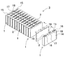
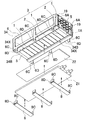
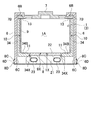
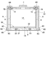
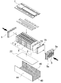
- FIG. It is a schematic sectional drawing of the power supply device for electric power shown in FIG. It is a disassembled perspective view which shows the manufacturing process of the potting resin layer of the power supply device shown in FIG. It is a schematic sectional drawing of the potting resin layer provided at the process shown in FIG. It is a schematic sectional drawing of the power supply device for electric power concerning the other Example of this invention. It is a disassembled perspective view which shows the manufacturing process of the potting resin layer of the power supply device shown in FIG. It is a schematic sectional drawing which shows the manufacturing process of the potting resin layer of the power supply device shown in FIG. It is a block diagram which shows the example which mounts a power supply device in the hybrid vehicle which drive
- the power supply device for electric power is mainly used in a power supply device that is mounted on an electric vehicle such as a hybrid car or an electric vehicle, supplies electric power to a traveling motor of the vehicle, and travels the vehicle, or a solar battery. It is used for a power supply device that stores the electric power and outputs it at night or during daytime peak power.
- 1 to 5 includes a battery block 3 in which a plurality of rectangular batteries 1 whose surface of an outer can 1A has conductivity are insulated by insulating separators 2 and arranged in a laminated state.
- a potting case 4 that covers both side surfaces of the battery block 3, a cooling plate 21 that cools the rectangular battery 1 of the battery block 3 from the bottom surface, and a cooling mechanism 20 that cools the cooling plate 21 are provided.
- the stacked rectangular batteries 1 are sandwiched by end plates 5 from both ends, and the end plates 5 are connected by bind bars 6. Further, the battery block 3 has a top cover 7 disposed on the upper surface, and the top cover 7 is fixed to the battery block 3 with a bind bar 6.
- the square battery 1 is a lithium ion secondary battery.
- the prismatic battery is not specified as a lithium ion secondary battery, and any battery that can be charged, such as a nickel metal hydride battery, can also be used.
- an electrode body in which positive and negative electrode plates are stacked is housed in an outer can 1A, filled with an electrolytic solution, and hermetically sealed.
- the outer can 1 ⁇ / b> A has a predetermined thickness in which an upper surface, both side surfaces, and a bottom surface are square, and an opening on the upper surface is airtightly closed with a sealing plate 1 ⁇ / b> B.
- the outer can 1A is obtained by deep-drawing a metal plate such as aluminum or an aluminum alloy, and has a conductive surface.
- This outer can is in the shape of a cylinder that is thinner than the width and has a rectangular shape on both sides facing each other, and closes the bottom surface.
- the sealing plate 1B is also made of a metal plate such as aluminum or aluminum alloy.
- positive and negative electrode terminals 15 are fixed to both ends via an insulating material 16.
- the positive and negative electrode terminals 15 are connected to built-in positive and negative electrode plates.
- the lithium ion secondary battery does not connect the outer can 1A to the electrode. However, since the outer can 1A is connected to the electrode plate via the electrolytic solution, it has an intermediate potential between the positive and negative electrode plates.
- the square battery 1 can also connect one electrode terminal 15 to an armored can with a lead wire.
- the rectangular battery 1 can be fixed to the sealing plate without insulating the electrode terminal 15 connected to the outer can.
- the sealing plate 1B is provided with an opening 18 of the safety valve 17.
- the safety valve 17 opens when the internal pressure of the outer can 1A becomes higher than a set value, and prevents the outer can 1A from being damaged.
- the safety valve 17 is opened, the internal gas is discharged to the outside from the opening 18 of the sealing plate 1B.
- the opening 18 of the safety valve 17 is provided in the sealing plate 1B. This outer can 1A can discharge gas from the opening 18 of the safety valve 17 to be opened.
- the prismatic battery can also be provided with a safety valve opening at the bottom or side of the outer can. However, in this rectangular battery, the electrolyte is discharged when the safety valve opens.
- the electrolytic solution is a conductive liquid, and if it is discharged, the contact portion may be short-circuited.
- the prismatic battery 1 in which the safety valve 17 is provided on the sealing plate 1B of the outer can 1A can discharge the gas from the safety valve 17 that is opened to reduce the internal pressure. For this reason, when the safety valve 17 is opened, the discharge of the electrolytic solution is restricted, and the adverse effects caused by the electrolytic solution can be reduced.
- the stacked rectangular batteries 1 are connected in series or in parallel with each other by connecting adjacent electrode terminals 15.
- the square batteries 1 connected in parallel do not generate a potential difference in the outer can.
- the power supply device that increases the output increases the output voltage by connecting all the rectangular batteries 1 in series without connecting them in parallel.
- the square battery 1 connected in series generates a potential difference between the outer can of the adjacent square battery 1. Therefore, the power supply device stacks the adjacent rectangular batteries 1 in an insulated state by sandwiching the insulating separator 2 between the outer cans of the adjacent rectangular batteries 1. Further, the insulating separator 2 sandwiched between the respective square batteries 1 is formed by thermally blocking and stacking the adjacent square batteries 1 so that the temperature of any one of the square batteries 1 becomes abnormally high and the thermal runaway occurs.
- the battery block 3 in which the insulating separator 2 is disposed also between the rectangular batteries 1 connected in parallel can prevent thermal runaway and improve safety.
- the end plate 5 is made of hard plastic or made of metal such as aluminum or its alloy.
- the end plate 5 has the same outer shape as the square battery 1 in order to sandwich the square battery 1 with a large area.
- the square end plate 5 is the same size as the rectangular battery 1 or slightly larger than the rectangular battery 1.
- the end plate 5 can be connected to the prismatic battery 1 so as not to be misaligned by forming a laminated surface with the prismatic battery 1 into a fitting structure.
- the end plate does not necessarily have a fitting structure with the prismatic battery, and any structure that can connect the prismatic battery and the end plate so as not to be displaced can be employed.
- the end of the bind bar 6 made of a metal plate is connected to the end plate 5. Both ends of the bind bar 6 are connected to the end plate 5 via set screws 19.
- the end plate 5 that connects the bind bar 6 with the set screw 19 is provided with a female screw hole 5 a into which the set screw 19 is screwed.
- the female screw hole 5 a is provided on the outer surface of the end plate 5, and connects the bind bar 6 by screwing a set screw 19 that passes through the bent portion 6 ⁇ / b> A of the bind bar 6.
- the bind bar 6 shown in the figure is fixed to the end plate 5 with a set screw 19, but the end of the bind bar is bent inward and connected to the end plate, or the end is crimped to the end plate. It can also be linked.
- the bind bar 6 in FIG. 1 has an up and down width that is substantially equal to the up and down width of the rectangular battery 1 and is lightened by notching the inside.
- the bind bar 6 is connected to the end plate 5 at the upper and lower ends.
- the end plate 5 is provided with female screw holes 5a above and below both sides of the outer surface. In this power supply device, the upper and lower ends of both ends of the bind bar 6 are fixed to the end plate 5.
- the end plate 5 that fixes the end portion of the bind bar 6 with the set screw 6 has a female screw hole 5 a at the connection position of the bind bar 6.
- the bind bar 6 is manufactured by processing a metal plate having a predetermined thickness into a predetermined width.
- the bind bar 6 fixes both ends to the end plate 5 and connects the pair of end plates 5 to hold the prismatic battery 1 in a compressed state.
- the bind bar 6 fixes the pair of end plates 5 to a predetermined size, and fixes the prismatic battery 1 stacked therebetween to a predetermined compressed state.
- the bind bar 6 is manufactured by processing a metal plate having a strength that does not extend due to the expansion pressure of the rectangular battery 1, for example, a stainless steel plate such as SUS304 or a metal plate such as a steel plate into a width and thickness having sufficient strength.
- the bind bar 6 is provided with a bent portion 6A at the end, and the bent portion 6A is fixed to the end plate 5.
- the bent portion 6A is provided with a through hole of a set screw 19 and is fixed to the end plate 5 via a set screw 19 inserted therein.
- the bind bar 6 is insert-molded into a plastic potting case 4 so that the potting case 4 and the bind bar 6 are integrated.
- the potting case 4 has an L-shaped cross-section and is divided into left and right parts, and covers both surfaces of the battery block 3 with each potting case 4.
- the potting case 4 is connected to each other by connecting the bind bar 6 formed by insert molding to the end plate 5, and further connected to each other via a connector 8 for fixing the cooling plate 21.
- the potting case 4 having an L-shaped cross section covers the side surface of the battery block 3 and the side portion of the bottom surface.
- the L-shaped potting case 4 has a shape in which a vertical portion 4A and a horizontal portion 4B are connected at a right angle, the vertical portion 4A covers the side surface of the battery block 3, and the horizontal portion 4B is a side portion on the bottom surface of the battery block 3.
- a vertical gap 4 ⁇ / b> A of the potting case 4 is provided with a filling gap 10 for filling the potting resin between the side surfaces of the battery block 3.
- the filling gap 10 is filled with potting resin, and a potting resin layer 9 is provided between the battery block 3 and the vertical portion 4 ⁇ / b> A of the potting case 4.
- the horizontal portion 4 ⁇ / b> B of the potting case 4 is in close contact with the bottom surface of the battery block 3 via the seal material 11 to prevent leakage of potting resin filled in the filling gap 10.
- the pair of potting cases 4 are connected to each other, the cooling surface 1X of the prismatic battery 1 is exposed between the horizontal portions 4B, and the cooling plate 21 is connected to the cooling surface 1X of the prismatic battery 1 in a thermally coupled state.
- An opening 4X is provided. 4 and 5, the heat conductive sheet 22 is disposed in the opening 4 ⁇ / b> X of the potting case 4, and the cooling plate 21 is fixed to the outer bottom surface of the horizontal portion 4 ⁇ / b> B of the potting case 4.
- the power supply device having this structure connects the cooling plate 21 to the cooling surface 1 ⁇ / b> X of the prismatic battery 1 in a thermally coupled state via the heat conductive sheet 22.
- the heat conductive sheet 22 is compressed and deformed between the prismatic battery 1 and the cooling plate 21, and is in close contact with the bottom surface of the prismatic battery 1 and the surface of the cooling plate 21 in a surface contact state.
- the thickness of the heat conductive sheet 22 in the uncompressed state is made slightly thicker than the thickness of the horizontal portion 4B of the potting case 4 so that the surface of the heat conductive sheet 22 is the cooling surface of the square battery 1. 1X and the surface of the cooling plate 21 can be adhered.
- the heat conductive sheet 22 is coated with an insulating heat conductive paste such as silicon oil on the surface thereof, so that the surface of the prismatic battery 1 and the surface of the cooling plate 21 are reliably and closely adhered to the surface contact state.
- a heat conductive paste is filled between the cooling surface of the prismatic battery and the surface of the cooling plate, and the cooling surface of the prismatic battery is connected to the cooling plate in a thermally coupled state via the heat conductive paste.
- the square battery can be connected to the surface of the cooling plate in a heat conductive state only with the heat conductive paste without necessarily using a heat conductive sheet.
- the above power supply device reliably and stably connects the cooling surface 1X of each rectangular battery 1 to the cooling plate 21 via the heat conductive sheet 22 or the heat conductive paste, so that each square battery 1 Cooling can be performed efficiently while reducing the temperature difference.
- the potting case 4 has a bind bar 6 fixed by insert molding protruding upward and downward.
- a part of the bind bar 6 that protrudes upward from the potting case 4 is a locking portion 6B that is bent in an L shape and locks the top cover 7, and is one of the bind bars 6 that protrude downward from the potting case 4.
- the part is a connecting piece 6 ⁇ / b> C that fixes the cooling plate 21.
- the L-shaped locking portion 6B bends the tip edge further downward and guides the tip edge to the guide groove 7B of the top cover 7.
- Sealing materials 12 and 13 are arranged between the top cover 7 and the locking portion 6B and between the top cover 7 and the battery block 3 to close the filling gap 10 filled with the potting resin.
- the sealing material 12 between the top cover 7 and the locking portion 6B is disposed between both side surfaces of the top cover 7 and the inside of the locking portion 6B, and the sealing material 13 between the top cover 7 and the battery block 3 is disposed.
- the power supply device that seals the filling gap 10 with the sealing materials 11, 12, 13 can prevent condensation on the surface of the battery block 3 by using the potting resin layer 9 as a close contact structure.
- the top cover 7 includes a circuit board (not shown) on which electronic components for realizing a protection circuit for the prismatic battery 1 are mounted.
- the top cover 7 connects the electrode terminals 15 of each rectangular battery 1 to a protection circuit via lead wires (not shown).
- the battery protection circuit detects the voltage of the battery via the lead wire, and controls the charge / discharge current so as to prevent the battery from being overcharged or overdischarged or to prevent the battery temperature from rising.
- the connecting piece 6C of the bind bar 6 protruding downward from the potting case 4 connects the connecting tool 8 bent at both ends upward, and the connecting plate 8 fixes the cooling plate 21 to the bottom surface of the battery block 3.
- the connection tool 8 is provided with a connection hole 8D in a bent portion 8C that is bent upward.
- the connecting piece 6C has a locking hook 6D that guides the connecting hole 8D and locks it so as not to come out of the connecting hole 8D.
- the connector 8 having this structure connects the bent portion 8C to the connecting piece 6C and fixes the cooling plate 21.
- the connecting tool 8 and the connecting piece 6 ⁇ / b> C have shapes and dimensions that allow the cooling plate 21 to be in close contact with the bottom surface of the potting case 4.
- This structure can be fixed in place so that the cooling plate 21 is not easily detached.
- you can fix the cooling plate to a fixed position by screwing the connector to the potting case or bind bar, and fix the cooling plate to the potting case or bind bar with a set screw. You can also
- a potting case 4 is provided outside the potting resin layer 9, and a cooling plate 21 is disposed outside the potting case 4. The exposed portion 9X for exposing the cooling surface 1X of the prismatic battery 1 to the potting resin layer 9 so that the cooling plate 21 arranged outside the potting case 4 is connected to the cooling surface 1X of the prismatic battery 1 in a thermally coupled state.
- the potting case 4 is provided with an opening 4X that exposes the cooling surface 1X of the prismatic battery 1.
- the cooling plate 21 disposed outside the potting case 4 is placed on the cooling surface 1X of the prismatic battery 1 through the opening 4X of the potting case 4 and the heat conductive sheet 22 disposed in the exposed portion 9X of the potting resin layer 9. It is connected to the thermal bond state.
- the above power supply device can cool the battery quickly and efficiently by the cooling plate 21 while securely holding the battery block 3 in place by both the potting case 4 and the potting resin layer 9.
- the potting resin layer 9 is provided by filling the filling gap 10 between the inner surface of the potting case 4 and the side surface of the battery block 3 with the potting resin.
- the thickness of the potting resin layer 9 is 0.5 mm to 10 mm.
- the potting resin is pasty or liquid in an uncured state, is filled in the filling gap 10, is cured here, and is fixed to the outer peripheral surface of the battery block 3.
- the potting resin can be filled into the filling gap 10 in an uncured state, and an insulating resin such as polyurethane, polyvinyl acetate, butyl rubber or the like can be used.
- the potting resin can be filled with heat conductive powder or heat conductive fiber having excellent heat conduction characteristics to improve the heat dissipation characteristics of the battery.
- alumina, glass beads, zinc oxide particles or the like can be used as the heat conductive powder, and glass fibers or the like can be used as the heat conductive fiber.
- the potting resin layer 9 does not cover the entire outer peripheral surface of the battery block 3.
- the potting resin layer 9 is provided with an exposed portion 9X that exposes the cooling surface 1X of the prismatic battery 1.
- a heat conductive sheet 22 is disposed in the exposed portion 9X, and the cooling surface 1X of the prismatic battery 1 is connected to the cooling plate 21 in a thermally coupled state in the exposed portion 9X.
- 1 to 5 has a cooling surface 1X of the prismatic battery 1 as a bottom surface.
- the cooling surface of the prismatic battery can be used as a side surface, and a cooling plate can be connected to the side surface in a thermally coupled state.
- the cooling plate 21 is provided with a refrigerant path 23 for circulating the refrigerant therein.
- the refrigerant path 23 is supplied with a refrigerant such as Freon or carbon dioxide in a liquid state, vaporizes the refrigerant therein, and cools the cooling plate 21 with heat of vaporization.
- the cooling plate 21 connects the refrigerant path 23 to the cooling mechanism 20.
- the cooling mechanism 20 includes a compressor 26 that pressurizes the gaseous refrigerant vaporized in the refrigerant path 23, a cooling heat exchanger 27 that cools and liquefies the refrigerant compressed by the compressor 26, and the cooling heat exchanger 27. And an expansion valve 28 for supplying the refrigerant liquefied in the refrigerant path 23.
- the liquid refrigerant supplied through the expansion valve 28 is vaporized in the refrigerant path 23 in the cooling plate 21, cools the cooling plate 21 with heat of vaporization, and is discharged to the cooling mechanism 20. Therefore, the refrigerant circulates through the refrigerant path 23 of the cooling plate 21 and the cooling mechanism 20 to cool the cooling plate 21.
- the cooling mechanism 20 cools the cooling plate 21 to a low temperature with the heat of vaporization of the refrigerant, but the cooling plate can also be cooled regardless of the heat of vaporization.
- the cooling plate supplies a refrigerant such as brine cooled to a low temperature to the refrigerant path, and cools the cooling plate directly with the low-temperature refrigerant instead of the heat of vaporization of the refrigerant.
- the cooling mechanism 20 controls the cooling state of the cooling plate 21 with a temperature sensor (not shown) that detects the temperature of the prismatic battery 1. That is, when the temperature of the prismatic battery 1 becomes higher than the preset cooling start temperature, the coolant is supplied to the cooling plate 21 for cooling, and when the prismatic battery 1 becomes lower than the cooling stop temperature, The supply of the refrigerant is stopped, and the rectangular battery 1 is controlled to a preset temperature range.
- the above power supply apparatus is assembled in the following steps. (1) A plurality of rectangular batteries 1 and insulating separators 2 are alternately stacked to form a battery block 3. A top cover 7 is arranged on the upper surface of the battery block 3 in which a plurality of prismatic batteries 1 are stacked, and a circuit board (not shown) mounted on the top cover 7 is respectively connected via a lead wire (not shown). Connected to the electrode terminal 15 of the rectangular battery 1.
- the end plates 5 are arranged at both ends of the battery block 3, the pair of end plates 5 are connected to the potting case 4 by a bind bar 6 that is insert-molded, and the top cover 7 is attached to the upper surface of the battery block 3. Secure with the bind bar 6.
- the seal material 13 is disposed between the top cover 7 and the upper surface of the battery block 3
- the seal material 12 is disposed between the top cover 7 and the bind bar 6.
- a sealing material 11 is also disposed between both sides of the bottom surface of the battery block 3 and the bottom surface inside the potting case 4 to seal the filling gap 10 provided between the top cover 7 and the battery block 3.
- the sealed filling gap 10 is provided so that a filling opening (not shown) for filling the potting resin is connected to the upper surface of the filling gap 10. The filling opening is closed after filling with the potting resin.
- the filling gap 10 is filled with uncured liquid or pasty potting resin from the filling opening.
- the potting resin is filled between the potting case 4 and the battery block 3 without any gap and cured.
- the potting resin to be cured becomes a potting resin layer 9 and is in close contact with each square battery 1 and further in close contact with the inner surface of the potting case 4 to fix each square battery 1 to the potting case 4.
- the heat conductive sheet 22 is disposed in the opening 4 ⁇ / b> X of the potting case 4.
- the cooling plate 21 is disposed on the bottom surface of the horizontal portion 4B of the potting case 4 so that the heat conductive sheet 22 is sandwiched between the bottom surface which is the cooling surface 1X of the rectangular battery 1 and the cooling plate 21.
- the connecting tool 8 is arranged on the lower surface of the cooling plate 21, and the bent portions 8C at both ends of the connecting tool 8 are connected to the connecting pieces 6C of the bind bar 6, The cooling plate 21 is fixed by the connector 8.
- the bind bar 6 is disposed outside the potting case 34 without insert-molding the bind bar 6 into the potting case.
- the bind bar 6 is provided with a locking portion 6B for locking the top cover 7 at the upper end in the same manner as the bind bar 6 of the power supply device shown in FIGS.
- a connecting piece 6C for fixing the plate 21 is provided at the lower end.
- the potting case 34 is provided with a notch 34a for providing an opening 34X on the bottom surface after filling the potting resin with the battery block 3 and curing it. .
- the cuts 34 a are provided in two rows along both sides of the bottom surface of the prismatic battery 1.
- the potting case 34 is a groove type that opens at both ends, and the inner shape of the groove type can be inserted into the battery block 3, and the potting resin is placed between the battery block 3 and the battery block 3. The shape is such that a filling gap 10 is formed.
- the potting resin layer 9 is provided on both sides of the battery block 3, and then the notch 34a of the potting case 34 is cut off as shown by the arrows in FIG. A portion 34X is provided, the heat conductive sheet 22 is disposed in the opening 34X, and the cooling plate 21 is fixed so as to sandwich the heat conductive sheet 22 outside.
- the cooling plate 21 is connected to the cooling surface 1X on the bottom surface of the rectangular battery 1 in a thermally coupled state, and the potting resin layers 9 are provided on both side surfaces which are part of the outer peripheral surface of the battery block 3.
- the potting resin layer 9 has an exposed portion 9X that exposes the cooling surface 1X of the prismatic battery 1, and a heat conductive sheet 22 is disposed on the exposed portion 9X so that the cooling surface 1X of the prismatic battery 1 is heated to the cooling plate 21. Linked to a combined state.
- This power supply device is assembled as follows. (1) A plurality of rectangular batteries 1 and insulating separators 2 are alternately stacked to form a battery block 3. A top cover 7 is arranged on the upper surface of the battery block 3 in which a plurality of prismatic batteries 1 are stacked, and a circuit board (not shown) mounted on the top cover 7 is respectively connected via a lead wire (not shown). Connected to the electrode terminal 15 of the rectangular battery 1.
- the battery block 3 is put in a potting case 34, end plates 5 are arranged at both ends of the potting case 34, the pair of end plates 5 are connected by a bind bar 6, and the top cover 7 Is fixed to the upper surface with the bind bar 6.
- the sealing material 11 is arranged between the inside of the bottom surface of the potting case 34 and both sides of the bottom surface of the battery block 3.
- the sealing material 13 is also disposed between the top cover 7 and the battery block 3, and the upper and lower portions of the filling gap 10 are sealed with the sealing materials 11 and 13.
- the sealed filling gap 10 is provided so that a filling opening (not shown) for filling the potting resin is connected to the upper surface of the filling gap 10. The filling opening is closed after filling with the potting resin.
- the filling gap 10 is filled with uncured liquid or pasty potting resin from the filling opening.
- the potting resin is filled between the potting case 34 and the battery block 3 without a gap and is cured.
- the potting resin to be cured becomes the potting resin layer 9 and is in close contact with each square battery 1 and is also in close contact with the inner surface of the potting case 34 to fix each square battery 1 to the potting case 34.
- the notch 34 a provided on the bottom surface of the potting case 34 is cut with a jig to remove the center portion 34 ⁇ / b> C of the bottom surface, and an opening 34 ⁇ / b> X is provided on the bottom surface of the potting case 34. .
- the heat conductive sheet 22 is disposed in the opening 4 ⁇ / b> X of the potting case 34.
- the cooling plate 21 is disposed outside the horizontal portion 34B of the potting case 34 so that the heat conductive sheet 22 is sandwiched between the cooling plate 1 and the bottom surface which is the cooling surface 1X of the square battery 1.
- the connecting tool 8 is arranged on the lower surface of the cooling plate 21, and the bent portions 8 ⁇ / b> C at both ends of the connecting tool 8 are connected to the connecting pieces 6 ⁇ / b> C of the bind bar 6.
- the cooling plate 21 is fixed with the tool 8.
- the power supply device shown in FIG. 12 uses the potting case 44 only for providing the potting resin layer 9, and after the potting resin layer 9 is provided, the potting case 44 is removed from the battery block 3 and the battery is bound by the bind bar 6. Block 3 is fixed.
- the bind bar 6 is also provided with a locking portion 6B for locking the top cover 7 at the upper end in the same manner as the bind bar 6 of the power supply device shown in FIGS.
- a connecting piece 6C for fixing the plate 21 is provided at the lower end.
- the potting case 44 is a groove type that opens at both ends.
- the inner shape of the groove type can be inserted into the battery block 3, and the battery block 3 is inserted into the battery block 3.
- the filling gap 10 for the potting resin is formed between both side surfaces. Openings at both ends of the potting case 44 are closed by the end plate 5. Accordingly, the outer shape of the end plate 5 is equal to the inner shape of the potting case 44, and the end plate 5 is disposed in the opening portions at both ends of the potting case 44 to close both ends of the potting case 44.
- This power supply device is assembled as follows. (1) As shown in FIG. 13 and FIG. 14, a heat conductive sheet 22 is laid on the bottom surface of a potting case 44 with a release agent 40 applied to the inner surface, and a plurality of rectangular batteries 1 are placed on the heat conductive sheet 22. The battery block 3 in which the separators 2 and the insulating separators 2 are alternately stacked is placed on the inside of the potting case 44. The end plates 5 are disposed at both ends of the potting case 44, and the end plates 5 are compressed from the outside by a press mechanism (not shown) to a predetermined size.
- the battery block 3 is held in a compressed state, and a circuit board (not shown) of the top cover 7 is connected to the electrode terminal 15 of each rectangular battery 1 via a lead wire (not shown).
- a top cover 7 is set on the upper surface of the battery block 3.
- the sealing material 11 is sandwiched between both sides of the lower surface of the top cover 7 and both sides of the upper surface of the battery block 3.
- the sealing material 11 closes the upper surface of the filling gap 10 provided between the potting case 4 and the battery block 3.
- the top-filled filling gap 10 is provided so that a filling opening (not shown) for filling the potting resin is connected to the top face of the filling gap 10. The filling opening is closed after filling with the potting resin.
- the filling gap 10 is filled with uncured liquid or pasty potting resin from the filling opening.
- the potting resin is filled between the potting case 44 and the battery block 3 without any gap and is cured.
- the potting resin to be cured becomes the potting resin layer 9 and is in close contact with each square battery 1. Since the release agent 40 is applied to the inner surface of the potting case 44, the cured potting resin layer 9 is not in close contact with the potting case 44.
- the battery block 3 is held in a compressed state by the end plate 5 and the potting case 44 is removed.
- the potting resin layer 9 is provided on both sides of the battery block 3, and the bottom surface of the battery block 3 is in a state where the heat conductive sheet 22 is in close contact with the exposed portion 9 ⁇ / b> X of the potting resin layer 9.
- both ends of the bind bar 6 are fixed to the pair of end plates 5. Further, the cooling plate 21 is fixed so as to be in close contact with the heat conductive sheet 22 in close contact with the bottom surface of the battery block 3, that is, the bottom surface that is the cooling surface 1 ⁇ / b> X of the rectangular battery 1.
- the cooling plate 21 is fixed to the bind bar 6 via the connector 8.
- the connector 8 is on the lower surface of the cooling plate 21, and both ends thereof are connected to the bind bar 6 to fix the cooling plate 21. Thereafter, the press mechanism (not shown) that has pressed the end plate 5 is removed.
- the above power supply device has a feature that it is light and compact because the outer surface of the battery block 3 is covered with the potting resin layer 9 and the potting case 4 is not provided.
- the above power supply devices can be used as in-vehicle power supplies.
- a vehicle equipped with a power supply device an electric vehicle such as a hybrid vehicle or a plug-in hybrid vehicle that runs with both an engine and a motor, or an electric vehicle that runs only with a motor can be used, and is used as a power source for these vehicles. .
- FIG. 15 shows an example in which a power supply device is mounted on a hybrid vehicle that runs with both an engine and a motor.
- a vehicle HV equipped with the power supply device 90 shown in this figure includes an engine 96 for traveling the vehicle HV and a motor 93 for traveling, a power supply device 90 for supplying power to the motor 93, and power generation for charging a battery of the power supply device 90.
- the power supply device 90 is connected to the motor 93 and the generator 94 via the DC / AC inverter 95.
- the vehicle HV travels by both the motor 93 and the engine 96 while charging / discharging the battery of the power supply device 90.
- the motor 93 is driven to drive the vehicle when the engine efficiency is low, for example, during acceleration or low-speed driving.
- the motor 93 is driven by power supplied from the power supply device 90.
- the generator 94 is driven by the engine 96 or is driven by regenerative braking when the vehicle is braked, and charges the battery of the power supply device 90.
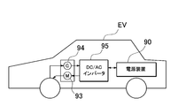
- FIG. 16 shows an example in which a power supply device is mounted on an electric vehicle that runs only with a motor.
- a vehicle EV equipped with the power supply device 90 shown in this figure includes a motor 93 for traveling the vehicle EV, a power supply device 90 that supplies power to the motor 93, and a generator that charges the battery of the power supply device 90. 94.
- the power supply device 90 is connected to the motor 93 and the generator 94 via the DC / AC inverter 95.
- the motor 93 is driven by power supplied from the power supply device 90.
- the generator 94 is driven by energy when regeneratively braking the vehicle EV, and charges the battery of the power supply device 90.
- this power supply apparatus can be used not only as a power source for a moving body but also as a stationary power storage facility.
- a power source for home and factory use a power supply system that is charged with sunlight or midnight power and discharged when necessary, or a streetlight power supply that charges sunlight during the day and discharges at night, or during a power outage It can also be used as a backup power source for driving signals.
- FIG. The power supply device 80 shown in this figure forms a battery unit 82 by connecting a plurality of battery packs 81 in a unit shape. In each battery pack 81, a plurality of rectangular batteries 1 are connected in series and / or in parallel.
- Each battery pack 81 is controlled by a power controller 84.
- the power supply device 80 drives the load LD after charging the battery unit 82 with the charging power supply CP. For this reason, the power supply device 80 has a charge mode and a discharge mode.
- the load LD and the charging power source CP are connected to the power supply device 80 via the discharging switch DS and the charging switch CS, respectively.
- ON / OFF of the discharge switch DS and the charge switch CS is switched by the power supply controller 84 of the power supply device 80.
- the power controller 84 switches the charging switch CS to ON and the discharging switch DS to OFF to permit charging from the charging power supply CP to the power supply device 80.
- the power controller 84 turns off the charging switch CS and turns on the discharging switch DS to discharge.
- the mode is switched to permit discharge from the power supply device 80 to the load LD.
- the charge switch CS can be turned on and the discharge switch DS can be turned on to supply power to the load LD and charge the power supply device 80 at the same time.
- the load LD driven by the power supply device 80 is connected to the power supply device 80 via the discharge switch DS.
- the power supply controller 84 switches the discharge switch DS to ON, connects to the load LD, and drives the load LD with the power from the power supply device 80.
- the discharge switch DS a switching element such as an FET can be used. ON / OFF of the discharge switch DS is controlled by the power supply controller 84 of the power supply device 80.
- the power controller 84 also includes a communication interface for communicating with external devices. In the example of FIG. 17, it is connected to the host device HT according to an existing communication protocol such as UART or RS-232C. Further, if necessary, a user interface for the user to operate the power supply system can be provided.
- Each battery pack 81 includes a signal terminal and a power supply terminal.
- the signal terminals include a pack input / output terminal DI, a pack abnormality output terminal DA, and a pack connection terminal DO.
- the pack input / output terminal DI is a terminal for inputting / outputting signals from other pack batteries and the power supply controller 84
- the pack connection terminal DO is for inputting / outputting signals to / from other pack batteries which are child packs.
- the pack abnormality output terminal DA is a terminal for outputting the abnormality of the battery pack to the outside.
- the power supply terminal is a terminal for connecting the battery packs 81 in series and in parallel.
- the battery units 82 are connected to the output line OL via the parallel connection switch 85 and are connected in parallel to each other.
- the power supply device can be suitably used as a power supply device for a plug-in hybrid electric vehicle, a hybrid electric vehicle, an electric vehicle or the like that can switch between the EV traveling mode and the HEV traveling mode.
- a backup power supply device that can be mounted on a rack of a computer server, a backup power supply device for a wireless base station such as a mobile phone, a power storage device for home use and a factory, a power supply for a street light, etc.
- it can be used as appropriate for applications such as a backup power source such as a traffic light.
- Electrode terminal 16 ... Insulating material 17 ... Safety valve 18 ... Opening 19 ... Set screw 20 ... Cooling mechanism 21 ... Cooling plate 22 ... Heat Conductive sheet 23 ... Refrigerant path 26 ... Compressor 27 ... Cooling heat exchanger 28 ... Expansion valve 34 ... Potting case 34a ... Notch 34B ... Horizontal part 34C ... Central part 34X ... Opening part 40 ... Release agent 44 ... Potting case 80 ... Power supply Device 81 ... Battery pack 82 ... Battery unit 84 ... Power supply controller 85 ... Parallel connection switch 90 ... Power supply device 93 ... Motor 94 ... Generator 95 ... DC / AC inverter 96 ... Engine EV, HV ... Vehicle LD ...
Landscapes
- Chemical & Material Sciences (AREA)
- Chemical Kinetics & Catalysis (AREA)
- Electrochemistry (AREA)
- General Chemical & Material Sciences (AREA)
- Engineering & Computer Science (AREA)
- Manufacturing & Machinery (AREA)
- Mechanical Engineering (AREA)
- Transportation (AREA)
- Aviation & Aerospace Engineering (AREA)
- Life Sciences & Earth Sciences (AREA)
- Sustainable Development (AREA)
- Sustainable Energy (AREA)
- Power Engineering (AREA)
- Combustion & Propulsion (AREA)
- Secondary Cells (AREA)
- Battery Mounting, Suspending (AREA)
Abstract
L'invention vise à fixer de manière fiable des batteries de forme rectangulaire respectives d'une manière stable tout en refroidissant de manière rapide et efficace les batteries de forme rectangulaire. A cet effet, l'invention concerne un dispositif de source d'énergie pour distribution d'énergie qui comprend : un bloc-batteries (3) dans lequel plusieurs batteries de forme rectangulaire (1) sont disposées en étant empilées ; une plaque de refroidissement (21) à la surface de ce bloc-batteries (3), disposée dans une condition de couplage thermique avec les batteries de forme rectangulaire respectives (1) et qui refroidit de manière forcée chacune de ces batteries rectangulaires (1) depuis la face inférieure de celles-ci ; et un mécanisme de refroidissement (20) qui refroidit cette plaque de refroidissement (21). Dans ce dispositif de source d'énergie, la plaque de refroidissement (21) est reliée à couplage thermique avec des faces de refroidissement (1X) constituant des faces inférieures ou des faces latérales des batteries de forme rectangulaire (1) et une couche de résine d'enrobage (9) est disposée à la face circonférentielle externe du bloc-batteries (3) ; de plus, cette couche de résine d'enrobage (9) comporte une section exposée (9X) par laquelle les faces de refroidissement (1X) des batteries de forme rectangulaire (1) sont exposées et les faces de refroidissement (1X) des batteries de forme rectangulaire (1) sont connectées à couplage thermique à la plaque refroidissante (21) au niveau de cette section exposée (9X).
Applications Claiming Priority (2)
| Application Number | Priority Date | Filing Date | Title |
|---|---|---|---|
| JP2011-124536 | 2011-06-02 | ||
| JP2011124536 | 2011-06-02 |
Publications (1)
| Publication Number | Publication Date |
|---|---|
| WO2012165493A1 true WO2012165493A1 (fr) | 2012-12-06 |
Family
ID=47259345
Family Applications (1)
| Application Number | Title | Priority Date | Filing Date |
|---|---|---|---|
| PCT/JP2012/063968 Ceased WO2012165493A1 (fr) | 2011-06-02 | 2012-05-30 | Dispositif de source d'énergie pour distribution d'énergie et véhicule comportant le dispositif de source d'énergie |
Country Status (1)
| Country | Link |
|---|---|
| WO (1) | WO2012165493A1 (fr) |
Cited By (21)
| Publication number | Priority date | Publication date | Assignee | Title |
|---|---|---|---|---|
| WO2014050109A1 (fr) * | 2012-09-27 | 2014-04-03 | 三洋電機株式会社 | Système de source d'énergie |
| JP2014116193A (ja) * | 2012-12-10 | 2014-06-26 | Toyota Industries Corp | 電池モジュール及び電池モジュールの製造方法 |
| JP2015207541A (ja) * | 2014-04-23 | 2015-11-19 | 日立建機株式会社 | 作業機械及びこれに搭載される蓄電装置の冷却構造 |
| WO2015197369A1 (fr) * | 2014-06-24 | 2015-12-30 | Mahle International Gmbh | Dispositif de transfert pour dispositif d'accumulation d'énergie et procédé de production d'un dispositif d'accumulation d'énergie |
| WO2016146840A1 (fr) * | 2015-03-19 | 2016-09-22 | Audi Ag | Véhicule automobile |
| JP2017059299A (ja) * | 2015-09-14 | 2017-03-23 | 株式会社豊田自動織機 | 電池パック及び電池モジュール |
| CN107757327A (zh) * | 2016-08-23 | 2018-03-06 | 本特勒尔汽车技术有限公司 | 用于电动机动车的蓄电池载体和用于装备并装配蓄电池载体的方法 |
| JP2018506831A (ja) * | 2015-03-04 | 2018-03-08 | エルジー・ケム・リミテッド | クランプ装置及びそれを含む電池モジュール |
| CN108389985A (zh) * | 2017-02-02 | 2018-08-10 | 罗伯特·博世有限公司 | 用于电池模块的模块壳体 |
| CN109478611A (zh) * | 2016-07-07 | 2019-03-15 | 三星Sdi株式会社 | 电池子模块载体、电池子模块、电池系统和汽车 |
| CN109904564A (zh) * | 2017-12-08 | 2019-06-18 | 利萨·德雷克塞迈尔有限责任公司 | 冷却设备、系统、车辆 |
| JP2020013750A (ja) * | 2018-07-20 | 2020-01-23 | 本田技研工業株式会社 | バッテリ装置及びバッテリ装置の製造方法 |
| CN112424988A (zh) * | 2018-07-17 | 2021-02-26 | 本田技研工业株式会社 | 蓄电池装置及蓄电池装置的制造方法 |
| US20210242527A1 (en) * | 2020-01-30 | 2021-08-05 | Robert Bosch Gmbh | Battery |
| JP2021140914A (ja) * | 2020-03-04 | 2021-09-16 | 三洋電機株式会社 | 電池パック |
| US11139521B2 (en) | 2016-07-07 | 2021-10-05 | Samsung Sdi Co., Ltd. | Battery submodule carrier, battery submodule, battery system and vehicle |
| US11685502B2 (en) * | 2020-06-30 | 2023-06-27 | Textron Innovations Inc. | Modular hybrid airframe structure for battery thermal event protection and repair |
| CN116666823A (zh) * | 2023-06-26 | 2023-08-29 | 欣旺达动力科技股份有限公司 | 电池包及用电设备 |
| JP2024525458A (ja) * | 2021-06-30 | 2024-07-12 | 東莞新能安科技有限公司 | 電池パックおよび電力消費機器 |
| EP4164031A4 (fr) * | 2020-11-16 | 2025-03-12 | LG Energy Solution, Ltd. | Dispositif de refroidissement de cellule de batterie, bloc-batterie le comprenant, et procédé de refroidissement de cellule de batterie utilisant celui-ci |
| EP4579877A4 (fr) * | 2022-08-30 | 2026-03-04 | Xiamen Ampack Technology Ltd | Bloc-batterie et dispositif électrique |
Citations (4)
| Publication number | Priority date | Publication date | Assignee | Title |
|---|---|---|---|---|
| JP2004087438A (ja) * | 2002-03-04 | 2004-03-18 | Nissan Motor Co Ltd | 組電池 |
| JP2009134901A (ja) * | 2007-11-28 | 2009-06-18 | Sanyo Electric Co Ltd | バッテリシステム |
| JP2009176689A (ja) * | 2008-01-28 | 2009-08-06 | Sanyo Electric Co Ltd | 電池パック |
| JP2010153141A (ja) * | 2008-12-24 | 2010-07-08 | Sanyo Electric Co Ltd | 車両用の電源装置 |
-
2012
- 2012-05-30 WO PCT/JP2012/063968 patent/WO2012165493A1/fr not_active Ceased
Patent Citations (4)
| Publication number | Priority date | Publication date | Assignee | Title |
|---|---|---|---|---|
| JP2004087438A (ja) * | 2002-03-04 | 2004-03-18 | Nissan Motor Co Ltd | 組電池 |
| JP2009134901A (ja) * | 2007-11-28 | 2009-06-18 | Sanyo Electric Co Ltd | バッテリシステム |
| JP2009176689A (ja) * | 2008-01-28 | 2009-08-06 | Sanyo Electric Co Ltd | 電池パック |
| JP2010153141A (ja) * | 2008-12-24 | 2010-07-08 | Sanyo Electric Co Ltd | 車両用の電源装置 |
Cited By (37)
| Publication number | Priority date | Publication date | Assignee | Title |
|---|---|---|---|---|
| WO2014050109A1 (fr) * | 2012-09-27 | 2014-04-03 | 三洋電機株式会社 | Système de source d'énergie |
| JP2014116193A (ja) * | 2012-12-10 | 2014-06-26 | Toyota Industries Corp | 電池モジュール及び電池モジュールの製造方法 |
| US9564668B2 (en) | 2012-12-10 | 2017-02-07 | Kabushiki Kaisha Toyota Jidoshokki | Battery module and method for manufacturing battery module |
| JP2015207541A (ja) * | 2014-04-23 | 2015-11-19 | 日立建機株式会社 | 作業機械及びこれに搭載される蓄電装置の冷却構造 |
| CN106463800B (zh) * | 2014-06-24 | 2019-07-23 | 马勒国际公司 | 用于储能设备的传递设备和用于制造储能设备的方法 |
| WO2015197369A1 (fr) * | 2014-06-24 | 2015-12-30 | Mahle International Gmbh | Dispositif de transfert pour dispositif d'accumulation d'énergie et procédé de production d'un dispositif d'accumulation d'énergie |
| CN106463800A (zh) * | 2014-06-24 | 2017-02-22 | 马勒国际公司 | 用于储能设备的传递设备和用于制造储能设备的方法 |
| JP2018506831A (ja) * | 2015-03-04 | 2018-03-08 | エルジー・ケム・リミテッド | クランプ装置及びそれを含む電池モジュール |
| US10870340B2 (en) | 2015-03-19 | 2020-12-22 | Audi Ag | Motor vehicle |
| WO2016146840A1 (fr) * | 2015-03-19 | 2016-09-22 | Audi Ag | Véhicule automobile |
| WO2017047211A1 (fr) * | 2015-09-14 | 2017-03-23 | 株式会社豊田自動織機 | Bloc-batterie et module de batteries |
| JP2017059299A (ja) * | 2015-09-14 | 2017-03-23 | 株式会社豊田自動織機 | 電池パック及び電池モジュール |
| US11139521B2 (en) | 2016-07-07 | 2021-10-05 | Samsung Sdi Co., Ltd. | Battery submodule carrier, battery submodule, battery system and vehicle |
| CN109478611A (zh) * | 2016-07-07 | 2019-03-15 | 三星Sdi株式会社 | 电池子模块载体、电池子模块、电池系统和汽车 |
| CN109478611B (zh) * | 2016-07-07 | 2021-11-09 | 三星Sdi株式会社 | 电池子模块载体、电池子模块、电池系统和汽车 |
| EP3482429A4 (fr) * | 2016-07-07 | 2020-03-11 | Samsung SDI Co., Ltd | Support de sous-module de batterie, sous-module de batterie, système de batterie et véhicule |
| US11075423B2 (en) | 2016-07-07 | 2021-07-27 | Samsung Sdi Co., Ltd. | Battery submodule carrier, battery submodule, battery system and vehicle |
| CN107757327A (zh) * | 2016-08-23 | 2018-03-06 | 本特勒尔汽车技术有限公司 | 用于电动机动车的蓄电池载体和用于装备并装配蓄电池载体的方法 |
| CN108389985A (zh) * | 2017-02-02 | 2018-08-10 | 罗伯特·博世有限公司 | 用于电池模块的模块壳体 |
| CN109904564A (zh) * | 2017-12-08 | 2019-06-18 | 利萨·德雷克塞迈尔有限责任公司 | 冷却设备、系统、车辆 |
| CN112424988A (zh) * | 2018-07-17 | 2021-02-26 | 本田技研工业株式会社 | 蓄电池装置及蓄电池装置的制造方法 |
| US20210265681A1 (en) * | 2018-07-17 | 2021-08-26 | Honda Motor Co., Ltd. | Battery device and method for manufacturing battery device |
| US11735785B2 (en) * | 2018-07-17 | 2023-08-22 | Honda Motor Co., Ltd. | Battery device including battery cell group configured by a plurality of laminated battery cells in outer packaging and method for manufacturing the battery device |
| CN112424988B (zh) * | 2018-07-17 | 2023-03-28 | 本田技研工业株式会社 | 蓄电池装置及蓄电池装置的制造方法 |
| JP7042181B2 (ja) | 2018-07-20 | 2022-03-25 | 本田技研工業株式会社 | バッテリ装置及びバッテリ装置の製造方法 |
| JP2020013750A (ja) * | 2018-07-20 | 2020-01-23 | 本田技研工業株式会社 | バッテリ装置及びバッテリ装置の製造方法 |
| US20210242527A1 (en) * | 2020-01-30 | 2021-08-05 | Robert Bosch Gmbh | Battery |
| US11699828B2 (en) * | 2020-01-30 | 2023-07-11 | Robert Bosch Gmbh | Battery including tensioning band bonded to side walls of battery cells by band bonding material |
| JP2021140914A (ja) * | 2020-03-04 | 2021-09-16 | 三洋電機株式会社 | 電池パック |
| JP7454411B2 (ja) | 2020-03-04 | 2024-03-22 | 三洋電機株式会社 | 電池パック |
| US11685502B2 (en) * | 2020-06-30 | 2023-06-27 | Textron Innovations Inc. | Modular hybrid airframe structure for battery thermal event protection and repair |
| EP4164031A4 (fr) * | 2020-11-16 | 2025-03-12 | LG Energy Solution, Ltd. | Dispositif de refroidissement de cellule de batterie, bloc-batterie le comprenant, et procédé de refroidissement de cellule de batterie utilisant celui-ci |
| JP2024525458A (ja) * | 2021-06-30 | 2024-07-12 | 東莞新能安科技有限公司 | 電池パックおよび電力消費機器 |
| EP4207456A4 (fr) * | 2021-06-30 | 2024-11-20 | Dongguan Poweramp Technology Limited | Bloc-batterie et dispositif électrique |
| JP7730477B2 (ja) | 2021-06-30 | 2025-08-28 | 寧徳新能源科技有限公司 | 電池パックおよび電力消費機器 |
| EP4579877A4 (fr) * | 2022-08-30 | 2026-03-04 | Xiamen Ampack Technology Ltd | Bloc-batterie et dispositif électrique |
| CN116666823A (zh) * | 2023-06-26 | 2023-08-29 | 欣旺达动力科技股份有限公司 | 电池包及用电设备 |
Similar Documents
| Publication | Publication Date | Title |
|---|---|---|
| WO2012165493A1 (fr) | Dispositif de source d'énergie pour distribution d'énergie et véhicule comportant le dispositif de source d'énergie | |
| JP7348180B2 (ja) | バッテリシステムとバッテリシステムを備える電動車両及び蓄電装置 | |
| KR101307992B1 (ko) | 높은 효율성의 냉각 구조를 포함하는 전지모듈 | |
| JP5734704B2 (ja) | 電源装置及び電源装置を備える車両 | |
| JP6328842B2 (ja) | 電源装置及びこれを備える車両 | |
| KR101560217B1 (ko) | 냉각 효율이 향상된 전지모듈 | |
| JP2013012441A (ja) | 電源装置及び電源装置を備える車両 | |
| JP6138688B2 (ja) | 電源装置及びこれを備える車両並びに蓄電装置 | |
| KR101547814B1 (ko) | 간접 공냉 구조를 포함하는 전지모듈 | |
| US20140023906A1 (en) | Power supply apparatus and vehicle having the same | |
| JP2012248339A (ja) | 電力用の電源装置及び電源装置を備える車両 | |
| JP2012160347A (ja) | 電源装置及び電源装置を備える車両 | |
| WO2013161654A1 (fr) | Dispositif d'alimentation électrique, véhicule comprenant le dispositif d'alimentation électrique, et dispositif de stockage d'électricité | |
| WO2014010438A1 (fr) | Système de batterie, et véhicule et dispositif de stockage d'énergie comprenant le système de batterie | |
| JP2013025983A (ja) | 電源装置及び電源装置を備える車両 | |
| WO2012133710A1 (fr) | Alimentation électrique et véhicule la comprenant | |
| WO2013084756A1 (fr) | Dispositif d'alimentation électrique, véhicule équipé dudit dispositif d'alimentation électrique, et dispositif de stockage électrique | |
| JP2015133169A (ja) | 電源装置及びこれを備える車両並びに蓄電装置 | |
| JP2013171746A (ja) | 電源装置及びこれを備える車両並びに蓄電装置 | |
| CN114207912B (zh) | 电源装置和使用该电源装置的电动车辆以及蓄电装置 | |
| WO2014024451A1 (fr) | Dispositif d'alimentation électrique, et véhicule électrique ainsi que dispositif d'accumulation électrique équipés de celui-ci | |
| WO2013031614A1 (fr) | Dispositif d'alimentation électrique ainsi que véhicule équipé de celui-ci, et dispositif de stockage | |
| WO2013002090A1 (fr) | Dispositif d'alimentation en énergie, véhicule comprenant ce dispositif, et procédé de fabrication d'un dispositif d'alimentation en énergie | |
| WO2021065160A1 (fr) | Module de batterie et véhicule électrique et dispositif de stockage d'énergie comprenant le module de batterie | |
| WO2012057169A1 (fr) | Dispositif d'alimentation, véhicule l'utilisant, élément de batterie et procédé de fabrication d'élément de batterie |
Legal Events
| Date | Code | Title | Description |
|---|---|---|---|
| 121 | Ep: the epo has been informed by wipo that ep was designated in this application |
Ref document number: 12793392 Country of ref document: EP Kind code of ref document: A1 |
|
| NENP | Non-entry into the national phase |
Ref country code: DE |
|
| 122 | Ep: pct application non-entry in european phase |
Ref document number: 12793392 Country of ref document: EP Kind code of ref document: A1 |
|
| NENP | Non-entry into the national phase |
Ref country code: JP |