WO2012165508A1 - Appareil de séchage par pulvérisation d'un filtrat issu des eaux usées de désulfuration et système de traitement des gaz d'échappement - Google Patents
Appareil de séchage par pulvérisation d'un filtrat issu des eaux usées de désulfuration et système de traitement des gaz d'échappement Download PDFInfo
- Publication number
- WO2012165508A1 WO2012165508A1 PCT/JP2012/063996 JP2012063996W WO2012165508A1 WO 2012165508 A1 WO2012165508 A1 WO 2012165508A1 JP 2012063996 W JP2012063996 W JP 2012063996W WO 2012165508 A1 WO2012165508 A1 WO 2012165508A1
- Authority
- WO
- WIPO (PCT)
- Prior art keywords
- exhaust gas
- spray drying
- drying apparatus
- desulfurization
- spray
- Prior art date
- Legal status (The legal status is an assumption and is not a legal conclusion. Google has not performed a legal analysis and makes no representation as to the accuracy of the status listed.)
- Ceased
Links
Images




Classifications
-
- B—PERFORMING OPERATIONS; TRANSPORTING
- B01—PHYSICAL OR CHEMICAL PROCESSES OR APPARATUS IN GENERAL
- B01D—SEPARATION
- B01D53/00—Separation of gases or vapours; Recovering vapours of volatile solvents from gases; Chemical or biological purification of waste gases, e.g. engine exhaust gases, smoke, fumes, flue gases, aerosols
- B01D53/34—Chemical or biological purification of waste gases
- B01D53/46—Removing components of defined structure
- B01D53/48—Sulfur compounds
- B01D53/50—Sulfur oxides
-
- B—PERFORMING OPERATIONS; TRANSPORTING
- B01—PHYSICAL OR CHEMICAL PROCESSES OR APPARATUS IN GENERAL
- B01D—SEPARATION
- B01D1/00—Evaporating
- B01D1/16—Evaporating by spraying
- B01D1/20—Sprayers
-
- B—PERFORMING OPERATIONS; TRANSPORTING
- B01—PHYSICAL OR CHEMICAL PROCESSES OR APPARATUS IN GENERAL
- B01D—SEPARATION
- B01D1/00—Evaporating
- B01D1/16—Evaporating by spraying
- B01D1/18—Evaporating by spraying to obtain dry solids
-
- B—PERFORMING OPERATIONS; TRANSPORTING
- B01—PHYSICAL OR CHEMICAL PROCESSES OR APPARATUS IN GENERAL
- B01D—SEPARATION
- B01D53/00—Separation of gases or vapours; Recovering vapours of volatile solvents from gases; Chemical or biological purification of waste gases, e.g. engine exhaust gases, smoke, fumes, flue gases, aerosols
- B01D53/14—Separation of gases or vapours; Recovering vapours of volatile solvents from gases; Chemical or biological purification of waste gases, e.g. engine exhaust gases, smoke, fumes, flue gases, aerosols by absorption
-
- B—PERFORMING OPERATIONS; TRANSPORTING
- B01—PHYSICAL OR CHEMICAL PROCESSES OR APPARATUS IN GENERAL
- B01D—SEPARATION
- B01D53/00—Separation of gases or vapours; Recovering vapours of volatile solvents from gases; Chemical or biological purification of waste gases, e.g. engine exhaust gases, smoke, fumes, flue gases, aerosols
- B01D53/34—Chemical or biological purification of waste gases
- B01D53/46—Removing components of defined structure
- B01D53/48—Sulfur compounds
- B01D53/50—Sulfur oxides
- B01D53/501—Sulfur oxides by treating the gases with a solution or a suspension of an alkali or earth-alkali or ammonium compound
- B01D53/504—Sulfur oxides by treating the gases with a solution or a suspension of an alkali or earth-alkali or ammonium compound characterised by a specific device
-
- B—PERFORMING OPERATIONS; TRANSPORTING
- B01—PHYSICAL OR CHEMICAL PROCESSES OR APPARATUS IN GENERAL
- B01D—SEPARATION
- B01D53/00—Separation of gases or vapours; Recovering vapours of volatile solvents from gases; Chemical or biological purification of waste gases, e.g. engine exhaust gases, smoke, fumes, flue gases, aerosols
- B01D53/34—Chemical or biological purification of waste gases
- B01D53/46—Removing components of defined structure
- B01D53/48—Sulfur compounds
- B01D53/50—Sulfur oxides
- B01D53/501—Sulfur oxides by treating the gases with a solution or a suspension of an alkali or earth-alkali or ammonium compound
- B01D53/505—Sulfur oxides by treating the gases with a solution or a suspension of an alkali or earth-alkali or ammonium compound in a spray drying process
-
- B—PERFORMING OPERATIONS; TRANSPORTING
- B01—PHYSICAL OR CHEMICAL PROCESSES OR APPARATUS IN GENERAL
- B01J—CHEMICAL OR PHYSICAL PROCESSES, e.g. CATALYSIS OR COLLOID CHEMISTRY; THEIR RELEVANT APPARATUS
- B01J2/00—Processes or devices for granulating materials, e.g. fertilisers in general; Rendering particulate materials free flowing in general, e.g. making them hydrophobic
- B01J2/02—Processes or devices for granulating materials, e.g. fertilisers in general; Rendering particulate materials free flowing in general, e.g. making them hydrophobic by dividing the liquid material into drops, e.g. by spraying, and solidifying the drops
- B01J2/04—Processes or devices for granulating materials, e.g. fertilisers in general; Rendering particulate materials free flowing in general, e.g. making them hydrophobic by dividing the liquid material into drops, e.g. by spraying, and solidifying the drops in a gaseous medium
-
- C—CHEMISTRY; METALLURGY
- C02—TREATMENT OF WATER, WASTE WATER, SEWAGE, OR SLUDGE
- C02F—TREATMENT OF WATER, WASTE WATER, SEWAGE, OR SLUDGE
- C02F1/00—Treatment of water, waste water, or sewage
- C02F1/02—Treatment of water, waste water, or sewage by heating
- C02F1/04—Treatment of water, waste water, or sewage by heating by distillation or evaporation
- C02F1/048—Purification of waste water by evaporation
-
- C—CHEMISTRY; METALLURGY
- C02—TREATMENT OF WATER, WASTE WATER, SEWAGE, OR SLUDGE
- C02F—TREATMENT OF WATER, WASTE WATER, SEWAGE, OR SLUDGE
- C02F1/00—Treatment of water, waste water, or sewage
- C02F1/02—Treatment of water, waste water, or sewage by heating
- C02F1/04—Treatment of water, waste water, or sewage by heating by distillation or evaporation
- C02F1/10—Treatment of water, waste water, or sewage by heating by distillation or evaporation by direct contact with a particulate solid or with a fluid, as a heat transfer medium
- C02F1/12—Spray evaporation
-
- F—MECHANICAL ENGINEERING; LIGHTING; HEATING; WEAPONS; BLASTING
- F23—COMBUSTION APPARATUS; COMBUSTION PROCESSES
- F23J—REMOVAL OR TREATMENT OF COMBUSTION PRODUCTS OR COMBUSTION RESIDUES; FLUES
- F23J15/00—Arrangements of devices for treating smoke or fumes
- F23J15/006—Layout of treatment plant
-
- F—MECHANICAL ENGINEERING; LIGHTING; HEATING; WEAPONS; BLASTING
- F26—DRYING
- F26B—DRYING SOLID MATERIALS OR OBJECTS BY REMOVING LIQUID THEREFROM
- F26B3/00—Drying solid materials or objects by processes involving the application of heat
- F26B3/02—Drying solid materials or objects by processes involving the application of heat by convection, i.e. heat being conveyed from a heat source to the materials or objects to be dried by a gas or vapour, e.g. air
- F26B3/10—Drying solid materials or objects by processes involving the application of heat by convection, i.e. heat being conveyed from a heat source to the materials or objects to be dried by a gas or vapour, e.g. air the gas or vapour carrying the materials or objects to be dried with it
- F26B3/12—Drying solid materials or objects by processes involving the application of heat by convection, i.e. heat being conveyed from a heat source to the materials or objects to be dried by a gas or vapour, e.g. air the gas or vapour carrying the materials or objects to be dried with it in the form of a spray, i.e. sprayed or dispersed emulsions or suspensions
-
- B—PERFORMING OPERATIONS; TRANSPORTING
- B01—PHYSICAL OR CHEMICAL PROCESSES OR APPARATUS IN GENERAL
- B01D—SEPARATION
- B01D2251/00—Reactants
- B01D2251/20—Reductants
- B01D2251/206—Ammonium compounds
-
- B—PERFORMING OPERATIONS; TRANSPORTING
- B01—PHYSICAL OR CHEMICAL PROCESSES OR APPARATUS IN GENERAL
- B01D—SEPARATION
- B01D2251/00—Reactants
- B01D2251/40—Alkaline earth metal or magnesium compounds
- B01D2251/404—Alkaline earth metal or magnesium compounds of calcium
-
- B—PERFORMING OPERATIONS; TRANSPORTING
- B01—PHYSICAL OR CHEMICAL PROCESSES OR APPARATUS IN GENERAL
- B01D—SEPARATION
- B01D2257/00—Components to be removed
- B01D2257/40—Nitrogen compounds
- B01D2257/404—Nitrogen oxides other than dinitrogen oxide
-
- B—PERFORMING OPERATIONS; TRANSPORTING
- B01—PHYSICAL OR CHEMICAL PROCESSES OR APPARATUS IN GENERAL
- B01D—SEPARATION
- B01D2257/00—Components to be removed
- B01D2257/60—Heavy metals or heavy metal compounds
- B01D2257/602—Mercury or mercury compounds
-
- B—PERFORMING OPERATIONS; TRANSPORTING
- B01—PHYSICAL OR CHEMICAL PROCESSES OR APPARATUS IN GENERAL
- B01D—SEPARATION
- B01D2258/00—Sources of waste gases
- B01D2258/02—Other waste gases
- B01D2258/0283—Flue gases
-
- C—CHEMISTRY; METALLURGY
- C02—TREATMENT OF WATER, WASTE WATER, SEWAGE, OR SLUDGE
- C02F—TREATMENT OF WATER, WASTE WATER, SEWAGE, OR SLUDGE
- C02F2103/00—Nature of the water, waste water, sewage or sludge to be treated
- C02F2103/18—Nature of the water, waste water, sewage or sludge to be treated from the purification of gaseous effluents
-
- F—MECHANICAL ENGINEERING; LIGHTING; HEATING; WEAPONS; BLASTING
- F23—COMBUSTION APPARATUS; COMBUSTION PROCESSES
- F23J—REMOVAL OR TREATMENT OF COMBUSTION PRODUCTS OR COMBUSTION RESIDUES; FLUES
- F23J2215/00—Preventing emissions
- F23J2215/20—Sulfur; Compounds thereof
-
- F—MECHANICAL ENGINEERING; LIGHTING; HEATING; WEAPONS; BLASTING
- F23—COMBUSTION APPARATUS; COMBUSTION PROCESSES
- F23J—REMOVAL OR TREATMENT OF COMBUSTION PRODUCTS OR COMBUSTION RESIDUES; FLUES
- F23J2219/00—Treatment devices
- F23J2219/60—Sorption with dry devices, e.g. beds
Definitions
- the present invention relates to a spray drying apparatus and an exhaust gas treatment system for dehydrated filtrate from desulfurization wastewater generated during exhaust gas treatment for treating exhaust gas discharged from a boiler.
- an exhaust gas treatment system for treating exhaust gas discharged from a boiler installed in a thermal power generation facility or the like.
- the exhaust gas treatment system includes a denitration device that removes nitrogen oxides from exhaust gas from a boiler, an air heater that recovers the heat of exhaust gas that has passed through the denitration device, a dust collector that removes soot and dust in the exhaust gas after heat recovery, and a post-dust removal And a desulfurization device for removing sulfur oxides in the exhaust gas.
- a desulfurization apparatus a wet desulfurization apparatus that removes sulfur oxide in the exhaust gas by bringing the lime absorbing liquid or the like into gas-liquid contact with the exhaust gas is generally used.
- Wastewater discharged from wet desulfurization equipment (hereinafter referred to as “desulfurization wastewater”) contains a large amount of various kinds of harmful substances such as ions such as chlorine ions and ammonium ions and mercury. For this reason, it is necessary to remove these harmful substances from the desulfurization effluent before the desulfurization effluent is discharged to the outside of the system, but the removal process of these various types of harmful substances contained in the desulfurization effluent is complicated, and the treatment cost There is a problem that is high. In order to reduce the treatment cost of the desulfurization waste water, a method for reusing the desulfurization waste water in the system without releasing it to the outside of the system has been proposed.
- Patent Documents 1 and 2 separately install a facility for branching from a flue in a main line to which a denitration apparatus, an air heater, a dust collector, and a desulfurization apparatus are connected, and spraying and degassing desulfurization drainage. Part of the exhaust gas from the line flue is introduced into this facility, and after desulfurization drainage is sprayed and evaporated in the exhaust gas in the facility to deposit harmful substances, this exhaust gas is then introduced into the main line flue.
- An exhaust gas treatment device configured to return is disclosed (Patent Documents 1 and 2).
- a spray dryer that dries desulfurization wastewater can be used as a facility for implementing this drainage, but there are the following problems when spraying and drying desulfurization wastewater using boiler exhaust gas.
- the boiler exhaust gas contains high-concentration ash, and when the desulfurization effluent is evaporated, a large amount of precipitated salt is present in the effluent, so that countermeasures are required.
- an object of the present invention is to provide a spray drying apparatus and an exhaust gas treatment system for dehydrated filtrate from desulfurization effluent from which desulfurization effluent from the desulfurization apparatus can be eliminated.
- a first invention of the present invention for solving the above-mentioned problems is provided in a side wall near the top of the spray drying apparatus main body, and a gas inlet for introducing exhaust gas for drying the spray liquid, and the spray drying apparatus main body
- a rectifying plate that decelerates the introduced exhaust gas and changes the exhaust gas flow into a laminar flow, a spray nozzle that sprays dehydrated filtrate from desulfurization wastewater into the laminar exhaust gas, and the spray drying device A gas discharge port for discharging exhaust gas that contributes to drying of the dehydrated filtrate provided on the side wall near the bottom of the main body, and a solid material discharging means for discharging spray-dried solid material provided at the bottom of the spray drying apparatus main body. It is in the spray-drying apparatus of the dehydrated filtrate from the desulfurization waste water characterized by comprising.
- a second invention is the desulfurization drainage according to the first invention, further comprising a protective plate provided in the vicinity of the exhaust gas introduction region in the spray drying apparatus main body and preventing wear of the inner wall surface due to solid content in the exhaust gas. From the dehydrated filtrate from the spray drying equipment.
- the third invention resides in a spray drying apparatus for dehydrated filtrate from desulfurization drainage, characterized in that in the first or second invention, the spray drying apparatus has a cleaning means for cleaning the inner wall peripheral surface of the spray drying apparatus.
- the 4th invention is the boiler which burns fuel, the air heater which collect
- Any one of the first to third units comprising a desulfurization apparatus for removing substances with an absorbing liquid, a dehydrator for removing gypsum from the desulfurization effluent discharged from the desulfurization apparatus, and a spraying means for spraying the dehydrated filtrate from the dehydrator
- An exhaust gas treatment system comprising one spray drying device and an exhaust gas introduction line for introducing a part of the exhaust gas into the spray drying device.
- the exhaust gas is made into a laminar flow, and the dehydrated filtrate from the desulfurization waste water is sprayed from the spray nozzle into the laminar exhaust gas, so that the dehydrated filtrate is spray dried. It becomes.
- the protection plate protects the wear caused by the introduced exhaust gas.
- FIG. 1 is a schematic configuration diagram of an exhaust gas treatment system according to a first embodiment.
- FIG. 2 is a schematic diagram of a spray drying apparatus for dehydrated filtrate from desulfurization effluent according to the first embodiment.
- 3A is a cross-sectional view taken along the line AA in FIG. 2, and is a schematic diagram illustrating an installation state of the first protective plate provided on the top side of the spray drying apparatus.
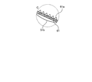
- FIG. 3-2 is an enlarged view of part C of FIG. 3-1.
- 4A is a cross-sectional view taken along the line BB of FIG. 2 and is a schematic diagram illustrating an installation state of a second protective plate provided on the bottom side of the spray drying apparatus.
- FIG. 4B is an enlarged view of a portion D in FIG.
- FIG. 5 is a schematic view of an apparatus for spray drying dehydrated filtrate from desulfurization effluent according to the second embodiment.
- FIG. 6 is a schematic diagram of a spray drying apparatus for dehydrated filtrate from des
- FIG. 1 is a schematic configuration diagram of an exhaust gas treatment system according to a first embodiment.
- An exhaust gas treatment system 10 illustrated in FIG. 1 includes, for example, exhaust gas 18 from a boiler 11 such as a coal fired boiler using coal as a fuel or a heavy oil fired boiler using heavy oil as a fuel, nitrogen oxide (NO x ), It is an apparatus for removing harmful substances such as sulfur oxide (SO x ) and mercury (Hg).
- a boiler 11 such as a coal fired boiler using coal as a fuel or a heavy oil fired boiler using heavy oil as a fuel
- NO x nitrogen oxide
- It is an apparatus for removing harmful substances such as sulfur oxide (SO x ) and mercury (Hg).
- the exhaust gas treatment system 10 includes a boiler 11 that burns fuel F, a denitration device 12 that removes nitrogen oxides in the exhaust gas 18 from the boiler 11, an air heater 13 that recovers the heat of the exhaust gas 18 after denitration, The dust collector 14 that removes the dust in the exhaust gas 18 after the recovery, the desulfurization device 15 that removes sulfur oxides contained in the exhaust gas 18 after the dust removal with the lime slurry 20 that is an absorbent, and the desulfurization device 15 are discharged.
- Denitration device 12 is a device for removing nitrogen oxides in the exhaust gas 18 supplied from the boiler 11 through the gas supply line L 1, and has inside thereof denitration catalyst layer (not shown).
- a reducing agent injector (not shown) is disposed upstream of the denitration catalyst layer, and the reducing agent is injected into the exhaust gas 18 from the reducing agent injector.
- ammonia, urea, ammonium chloride or the like is used as the reducing agent.
- the nitrogen oxides in the exhaust gas 18 introduced into the denitration device 12 come into contact with the denitration catalyst layer, so that the nitrogen oxides in the exhaust gas 18 are decomposed and removed into nitrogen gas (N 2 ) and water (H 2 O). Is done.
- the mercury in the exhaust gas 18 increases in the chlorine (Cl) content, the proportion of divalent mercury chloride that is soluble in water increases, and mercury is easily collected by the desulfurization device 15 described later.
- the denitration device 12 is not essential, and when the nitrogen oxide concentration or mercury concentration in the exhaust gas 18 from the boiler 11 is very small, or when these substances are not contained in the exhaust gas 18, denitration is performed. It is also possible to omit the device 12.
- the air heater 13 is a heat exchanger that recovers heat in the exhaust gas 18 supplied through the exhaust gas supply line L 2 after nitrogen oxides are removed by the denitration device 12. Since the temperature of the exhaust gas 18 that has passed through the denitration device 12 is as high as about 300 ° C. to 400 ° C., heat exchange is performed between the high temperature exhaust gas 18 and the normal temperature combustion air by the air heater 13. The combustion air that has reached a high temperature due to heat exchange is supplied to the boiler 11. On the other hand, the exhaust gas 18 subjected to heat exchange with room temperature combustion air is cooled to about 150 ° C.
- the dust collector 14 removes soot and dust in the exhaust gas 18 supplied via the gas supply line L 3 after heat recovery.
- the dust collector 14 include an inertial dust collector, a centrifugal dust collector, a filtration dust collector, an electric dust collector, and a cleaning dust collector, but are not particularly limited.
- symbol 16 in FIG. 1 illustrates dust collection ash.
- the desulfurization device 15 is a device that removes sulfur oxide in the exhaust gas 18 supplied via the gas supply line L 4 in a wet manner after the dust is removed.
- lime slurry 20 an aqueous solution in which limestone powder is dissolved in water
- the temperature in the apparatus is adjusted to about 30 to 80 ° C.
- the lime slurry 20 is supplied from the lime slurry supply device 21 to the tower bottom 22 of the desulfurization device 15.
- the lime slurry 20 supplied to the tower bottom 22 of the desulfurization apparatus 15 is sent to a plurality of nozzles 23 in the desulfurization apparatus 15 via an absorption liquid supply line (not shown), and ejected from the nozzle 23 toward the tower top 24 side. Is done.
- an absorption liquid supply line not shown
- sulfur oxide and mercury chloride in the exhaust gas 18 are absorbed by the lime slurry 20, It is separated from the exhaust gas 18 and removed.
- the exhaust gas 18 purified by the lime slurry 20 is discharged from the tower top 24 side of the desulfurization device 15 as the purified gas 26 and is discharged out of the system from the chimney 27.
- the sulfur oxide SO x in the exhaust gas 18 causes a reaction represented by the lime slurry 20 and the following formula (1).
- the lime slurry 20 that has absorbed SO x in the exhaust gas 18 is oxidized by air (not shown) supplied to the tower bottom 22 of the desulfurization device 15, and the reaction represented by the following equation (2) with air.
- air (not shown) supplied to the tower bottom 22 of the desulfurization device 15, and the reaction represented by the following equation (2) with air.
- SO x in the exhaust gas 18 is captured in the form of gypsum CaSO 4 .2H 2 O in the desulfurization apparatus 15.
- the lime slurry 20 is obtained by pumping the liquid stored in the tower bottom 22 of the desulfurization device 15, and the lime slurry 20 to be pumped is accompanied by the operation of the desulfurization device 15.
- Gypsum CaSO 4 .2H 2 O is mixed according to the reaction formulas (1) and (2).
- this lime-gypsum slurry (lime slurry mixed with gypsum) to be pumped is called an absorbent.
- Absorbing solution used for desulfurization (limestone gypsum slurry) is discharged from the bottom portion 22 of the desulfurization apparatus 15 to the outside as a desulfurization effluent 30 is sent to the dehydrator 32 through the drain line L 20 to be described later, wherein the dehydration treatment Is done.
- the desulfurization waste water 30 contains heavy metals such as mercury and halogen ions such as Cl ⁇ , Br ⁇ , I ⁇ and F ⁇ .
- the dehydrator 32 separates the solid component containing the gypsum 31 in the desulfurization waste water 30 and the dehydrated filtrate 33 of the liquid component.
- the dehydrator 32 for example, a belt filter, a centrifugal separator, a decanter type centrifugal sedimentator or the like is used.
- the gypsum 31 is separated by a dehydrator 32.
- mercury chloride in the desulfurization waste water 30 is separated from the liquid together with the gypsum 31 in a state of being adsorbed on the gypsum 31.
- the separated gypsum 31 is discharged outside the system (hereinafter referred to as “outside of the system”).
- the dehydrated filtrate 33 as a separated liquid is sent to the spray drying apparatus 50 via the dehydration line L 21 .
- the dehydrated filtrate 33 may be temporarily stored in a drain tank (not shown).
- the spray drying apparatus 50 includes a gas introduction means in which a part of the exhaust gas 18 is introduced via an exhaust gas introduction line L 11 branched from the exhaust gas supply line L 2 which is a main line of the exhaust gas 18 from the boiler 11, and a dehydrated filtrate 33. Spraying means for spraying or spraying. Then, the dehydrated filtrate 33 sprayed or sprayed by the heat of the introduced exhaust gas 18 is evaporated and dried.
- Reference numeral L 12 denotes an exhaust gas supply line for supplying the exhaust gas 18 that has contributed to drying by the spray drying device 50 to the gas supply line L 3 .
- the dehydrated filtrate 33 from which the gypsum 31 has been removed from the desulfurization waste water 30 is spray-dried, clogging by the spraying means can be prevented. That is, since the desulfurization wastewater itself is not sprayed, the amount of dry particles generated as the desulfurization wastewater evaporates can be greatly reduced. As a result, clogging due to adhesion of dry particles can be reduced. Further, by dehydrating the desulfurization waste water 30, mercury chloride is separated and removed together with the gypsum 31, so that it is possible to prevent the mercury concentration in the exhaust gas 18 from increasing when spraying the waste water.
- part of the exhaust gas 18 flowing into the air heater 13 is branched from the exhaust gas supply line L 2 via the exhaust gas introduction line L 11 , so that the temperature of the exhaust gas is high (350 to 400 ° C.) Spray drying of the dehydrated filtrate 33 can be performed efficiently.
- FIG. 2 is a schematic view of a spray drying apparatus for dehydrated filtrate from desulfurization effluent according to the present embodiment.
- the spray drying apparatus 50A of the present embodiment is provided on the side wall 51b near the top (lid) part 51a of the spray drying apparatus main body, and introduces the exhaust gas 18 for drying the spray liquid 33a of the dehydrated filtrate 33.
- the spray drying apparatus main body decelerates the introduced exhaust gas 18 and changes the exhaust gas flow into the laminar flow X, and the laminar flow X into the exhaust gas 18.
- reference numeral 56 indicates ash which is a spray-dried solid.
- the first region for preventing wear of the inner wall surface 51d due to the solid content in the exhaust gas 18 is introduced into each of the introduction region of the exhaust gas 18 in the main body of the spray drying apparatus 50A and the exhaust region of the exhaust gas 18 that contributes to drying.
- the protective plate 61 and the second protective plate 62 are provided along the wall. This is because the exhaust gas 18 to be introduced has a flow rate of, for example, about 10 to 18 m / s, and the exhaust gas 18 is introduced from the tangential direction of the apparatus main body. The inner wall surface 51d is prevented from being worn.
- FIG. 3A is a cross-sectional view taken along the line AA of FIG. 2, and is a schematic view showing an installation state of the first protective plate 61 provided on the top side of the spray drying apparatus.
- FIG. 3-2 is an enlarged view of the C part.
- 4A is a cross-sectional view taken along the line BB in FIG. 2, and is a schematic diagram illustrating an installation state of the second protective plate 62 provided on the bottom side of the spray drying apparatus.
- FIG. 4B is an enlarged view of the D part.
- a rail-shaped insertion jig 63 is provided on the inner wall surface 51d in the main body of the spray drying apparatus 50A.
- the first protective plate 61 can be easily pulled out in the vertical axis direction with respect to the insertion jig 63 and can be replaced as necessary.
- an insertable first protective plate 61 is provided along the periphery of the inner wall surface 51d.
- the introduction of the exhaust gas 18 may be performed by introducing the exhaust gas 18 into the spray drying device 50A due to the difference in pressure loss between the exhaust gas supply line L 2 and the exhaust gas introduction line L 11 , or by introducing an induction fan or the like as necessary.
- the exhaust gas 18 is introduced.
- an uneven surface 61a is further formed on the surface of the first protective plate 61, and the flow of the exhaust gas 18 is decelerated by the uneven surface 61a.
- the concave / convex surface 61a which is a speed reduction means, is formed on the first protective plate 61, but the present invention is not limited to this, and a gas speed reduction means may be provided independently.
- the exhaust gas 18 that has collided with the first protective plate 61 is provided with a rectifying plate 53 in order to further weaken the vortex flow.
- the rectifying plate 53 according to this embodiment is provided by a support means (not shown) radially from the supply pipe 54a of the dehydrated filtrate 33 supplied to the spray nozzle 54.
- the rectifying plate 53 changes the exhaust gas 18 from a vortex flow (swirl flow) to a laminar flow X downward flow.
- the rectifying plate 53 may also be provided on the inner wall surface 51d side in the vertical axis direction.
- the dehydrated filtrate 33 is sprayed from the spray nozzle 54 as the spray liquid 33a into the exhaust gas 18 that has become the laminar flow X.
- the form of the spray nozzle 54 is not limited as long as it sprays the dehydrated filtrate 33 to have a predetermined droplet diameter.
- a spraying means such as a two-fluid nozzle or a rotary atomizer can be used.
- the two-fluid nozzle is suitable for spraying a relatively small amount of the dehydrated filtrate 33
- the rotary atomizer is suitable for spraying a relatively large amount of the dehydrated filtrate 33.
- the number of nozzles is not limited to one, and a plurality of nozzles may be provided according to the processing amount.
- a cleaning means for cleaning the inner wall peripheral surface of the spray drying apparatus 50A.
- This cleaning means has a cleaning nozzle 71 that sprays the cleaning liquid 72 over the entire inner wall surface 51d and forms a wet wall 72a, and a recovery rod 73 that recovers the liquid falling on the wet wall 72a.
- the wetting wall 72a is formed over the entire inner wall surface 51d, and prevents the deposits that are deposited from the exhaust gas 18 and the dehydrated filtrate 33 from being generated.
- This cleaning means may be installed as necessary, and the cleaning means may be omitted when the amount of deposits is small.
- the spray drying region in the tower of the spray drying apparatus 50A is a desulfurized filtrate having a boiling point higher than that of general water so that the spray liquid 33a sprayed from the spray nozzle 54 can be satisfactorily dried.
- the length is changed according to the evaporation rate of the filtrate so that the residence time of the spray liquid 33a is lengthened.
- the exhaust gas 18 that has contributed to the spray drying is discharged from a gas discharge port 55 provided on the side wall 51c near the bottom of the spray drying apparatus 50A.
- a plurality of second protection plates 62 are provided along the wall as shown in FIG. .
- the surface of the second protective plate 62 is a smooth surface unlike the surface of the first protective plate 61. Note that the second protective plate 62 may be omitted depending on the amount of dust contained in the exhaust gas.
- the dehydrated filtrate 33 when the dehydrated filtrate 33 is sprayed from the spray nozzle 54, it comes into contact with the introduced exhaust gas 18 and is spray-dried.
- the dehydrated filtrate 33 contains various salts.
- the ash 56 which is the spray-dried solid, is discharged from a discharge hopper 57 provided at the bottom of the spray-drying apparatus main body.
- a third protective plate 64 is also provided on the inner wall surface of the discharge hopper 57 in order to prevent corrosion due to abrasion with the ash 56. Since the third protective plate 64 installed in the discharge hopper 57 may not be easily replaced, a ceramic tile or the like that is durable in a corrosive environment such as ash wear or precipitated salt is pasted. It may be.
- the exhaust gas 18 is converted into a laminar flow X by the rectifying plate 53, and the dehydrated filtrate 33 from the desulfurization waste water 30 is sprayed into the exhaust gas 18 that has become the laminar flow X by the spray nozzle 54.
- the spray drying of the dehydrated filtrate 33 is improved.
- the wear due to the exhaust gas 18 colliding with the inner wall surface 51d during introduction and discharge is protected by the first and second protection plates 61 and 62, the durability of the spray drying apparatus is improved.
- the spray drying apparatus 50A has a cleaning means for cleaning the inside of the spray drying apparatus 50A, and by cleaning with the wet wall 72a, the high concentration ash in the exhaust gas 18 and a large amount of deposited salt after spray drying are cleaned. In addition, since the generation of scale can be prevented, the durability of the spray drying apparatus 50A is improved.
- FIG. 5 is a schematic view of an apparatus for spray drying dehydrated filtrate from desulfurization effluent according to the second embodiment.
- the spray drying apparatus 50A of Example 1 the same code
- the spray drying apparatus 50 ⁇ / b> B of the present embodiment is provided with ash dispensing means 80 for dispensing ash 56 at the bottom of the spray drying apparatus main body.
- the ash discharge means 80 is provided in connection with the discharge hopper 57, and is provided with a fixed platen 81 having an opening 81a therein and a rotating platen 82 that rotates by rotation of an endless belt 84 that rotates by driving of a motor 83. ing.
- the turntable 82 is provided with an opening 82a.
- the rotating plate 82 is rotated by the endless belt 84 by driving the motor 83, the openings 81a and 82a are aligned, and the ash 56 is dropped into the lower discharge passage 86. ing.
- a compressor 85 is installed at one end of the discharge passage 86, and the ash 56 is pumped by the compressor 85 and sent to an ash collection facility 87 provided at the other end of the discharge passage 86.
- a third protection plate 64 is provided on the inner surface of the communication passage 88 in which the ash discharging means 80 is interposed, so that the inner surface of the communication passage 88 is protected.
- a vibration device 89 is provided around the discharge hopper 57, and the discharge hopper 57 is vibrated to prevent clogging of ash and deposited salt. Furthermore, the discharge hopper 57, the discharge passage 86, and the communication passage 88 are provided with heat retaining means (for example, a steam trace) so as not to clog ash and deposited salt.
- FIG. 6 is a schematic diagram of a spray drying apparatus for dehydrated filtrate from desulfurized wastewater according to Example 3.
- the spray drying apparatus 50A of Example 1 the same code
- the spray drying apparatus 50 ⁇ / b> C of the present embodiment is provided with a cleaning liquid storage tank 74 for collecting and reusing the cleaning liquid 72 of the cleaning means.
- Spray-drying apparatus wetted wall 72a formed on the inner surface of the body is washed away deposits precipitated, the cleaning liquid 72 is recovered by the recovery gutter 73, the recovery line L 31, is collected in the cleaning liquid storage tank 74, The cleaning liquid 72 is supplied again to the cleaning nozzle 71 through the cleaning liquid supply line L 32 by the circulation pump 75.
- the concentration of the cleaning liquid 72 increases, so that dilution water 76 is appropriately supplied to dilute. Further, when the concentration rises above a predetermined level, a part of the cleaning liquid 72 is extracted from the cleaning liquid storage tank 74, diluted by the diluted water 76 by the extracted amount, and cleaned again.
Landscapes
- Engineering & Computer Science (AREA)
- Chemical & Material Sciences (AREA)
- Chemical Kinetics & Catalysis (AREA)
- Environmental & Geological Engineering (AREA)
- Organic Chemistry (AREA)
- Life Sciences & Earth Sciences (AREA)
- Oil, Petroleum & Natural Gas (AREA)
- Analytical Chemistry (AREA)
- General Chemical & Material Sciences (AREA)
- Health & Medical Sciences (AREA)
- Biomedical Technology (AREA)
- Hydrology & Water Resources (AREA)
- Water Supply & Treatment (AREA)
- General Engineering & Computer Science (AREA)
- Mechanical Engineering (AREA)
- Physics & Mathematics (AREA)
- Thermal Sciences (AREA)
- Microbiology (AREA)
- Treating Waste Gases (AREA)
- Heat Treatment Of Water, Waste Water Or Sewage (AREA)
- Gas Separation By Absorption (AREA)
- Vaporization, Distillation, Condensation, Sublimation, And Cold Traps (AREA)
Abstract
La présente invention concerne un appareil de séchage par pulvérisation comportant un orifice d'entrée de gaz (52) situé dans une paroi latérale (51b) au voisinage du (couvercle recouvrant le) haut (51a) de l'appareil de séchage par pulvérisation (50A) et qui permet l'introduction d'un gaz d'échappement (18) en vue du séchage de gouttelettes (33a) de filtrat (33) ; des panneaux de réglage de l'écoulement (53) qui sont situés dans le corps de l'appareil de séchage par pulvérisation et qui sont destinés à transformer le flux de gaz d'échappement en un flux laminaire (X) et à ralentir le gaz d'échappement introduit (18) ; une buse de pulvérisation permettant de pulvériser le filtrat (33) issu des eaux usées de désulfuration (30) dans le gaz d'échappement (18) à flux laminaire (X) ; un orifice d'évacuation de gaz (55) qui est situé dans une paroi latérale (51c) au voisinage du fond de l'appareil de séchage par pulvérisation et qui permet l'évacuation du gaz d'échappement (18) ayant contribué au séchage du filtrat (33) ; et une trémie d'évacuation (57) qui est située du côté du fond de l'appareil de séchage par pulvérisation et qui sert de moyen d'élimination des particules solides séchées par pulvérisation, tels que la cendre (56).
Priority Applications (6)
| Application Number | Priority Date | Filing Date | Title |
|---|---|---|---|
| KR1020137031134A KR20140018971A (ko) | 2011-05-31 | 2012-05-30 | 탈황 배수로부터의 탈수 여과액의 분무 건조 장치 및 배기 가스 처리 시스템 |
| ES12793771T ES2804262T3 (es) | 2011-05-31 | 2012-05-30 | Aparato de secado por pulverización para el filtrado de aguas residuales de desulfuración y sistema de tratamiento de gases de escape |
| US14/116,073 US9527004B2 (en) | 2011-05-31 | 2012-05-30 | Spray drying apparatus of dehydration filtrate from desulfurization waste water, and air pollution control system |
| PL12793771T PL2716349T3 (pl) | 2011-05-31 | 2012-05-30 | Urządzenie do suszenia rozpyłowego dla filtratu z układu odsiarczania ścieków i obróbki gazów spalinowych |
| EP12793771.2A EP2716349B1 (fr) | 2011-05-31 | 2012-05-30 | Appareil de séchage par pulvérisation d'un filtrat issu des eaux usées de désulfuration et système de traitement des gaz d'échappement |
| CN201280024651.3A CN103547355A (zh) | 2011-05-31 | 2012-05-30 | 来自脱硫废水的脱水滤液的喷雾干燥装置及废气处理系统 |
Applications Claiming Priority (2)
| Application Number | Priority Date | Filing Date | Title |
|---|---|---|---|
| JP2011-122501 | 2011-05-31 | ||
| JP2011122501A JP5888878B2 (ja) | 2011-05-31 | 2011-05-31 | 脱硫排水からの脱水濾液の噴霧乾燥装置及び排ガス処理システム |
Publications (1)
| Publication Number | Publication Date |
|---|---|
| WO2012165508A1 true WO2012165508A1 (fr) | 2012-12-06 |
Family
ID=47259360
Family Applications (1)
| Application Number | Title | Priority Date | Filing Date |
|---|---|---|---|
| PCT/JP2012/063996 Ceased WO2012165508A1 (fr) | 2011-05-31 | 2012-05-30 | Appareil de séchage par pulvérisation d'un filtrat issu des eaux usées de désulfuration et système de traitement des gaz d'échappement |
Country Status (8)
| Country | Link |
|---|---|
| US (1) | US9527004B2 (fr) |
| EP (1) | EP2716349B1 (fr) |
| JP (1) | JP5888878B2 (fr) |
| KR (1) | KR20140018971A (fr) |
| CN (1) | CN103547355A (fr) |
| ES (1) | ES2804262T3 (fr) |
| PL (1) | PL2716349T3 (fr) |
| WO (1) | WO2012165508A1 (fr) |
Cited By (9)
| Publication number | Priority date | Publication date | Assignee | Title |
|---|---|---|---|---|
| CN106377994A (zh) * | 2016-10-27 | 2017-02-08 | 上海交通大学 | 一种湿式钙基烟气脱硫系统及其应用 |
| CN106512456A (zh) * | 2016-10-14 | 2017-03-22 | 北京姚魏环保技术有限公司 | 一种脱硫废水的四段法蒸发装置及方法 |
| JP2017104785A (ja) * | 2015-12-08 | 2017-06-15 | アイエス ジャパン株式会社 | Cipアダプタ及びcipシステム |
| CN108285188A (zh) * | 2018-03-13 | 2018-07-17 | 南京常荣声学股份有限公司 | 一种余热利用协同脱硫废水零排放及去烟羽的装置和方法 |
| CN112807985A (zh) * | 2021-02-03 | 2021-05-18 | 陕西龙门钢铁有限责任公司 | 加速脱硫除尘灰仓放灰的装置 |
| CN114702094A (zh) * | 2021-12-22 | 2022-07-05 | 国电电力邯郸东郊热电有限责任公司 | 一种燃煤电厂末端废水和末端固废的综合处理系统 |
| CN115959731A (zh) * | 2022-11-22 | 2023-04-14 | 苏州海派特热能设备有限公司 | 一种用于电厂废水零排放的浓缩蒸发装置 |
| CN116726687A (zh) * | 2023-06-13 | 2023-09-12 | 山东蓝诺机械制造有限公司 | 一种有机废气处理用多功能喷射装置及其处理工艺 |
| CN116870686A (zh) * | 2023-08-14 | 2023-10-13 | 洛阳市亿鑫环保科技有限公司 | 一种低温大风量烟气脱硫脱硝净化设备及方法 |
Families Citing this family (28)
| Publication number | Priority date | Publication date | Assignee | Title |
|---|---|---|---|---|
| JP5773756B2 (ja) | 2011-05-31 | 2015-09-02 | 三菱日立パワーシステムズ株式会社 | 脱水濾液の噴霧乾燥装置及び排ガス処理システム |
| JP2014140823A (ja) | 2013-01-24 | 2014-08-07 | Mitsubishi Heavy Ind Ltd | 排ガス処理システム及び排ガス処理方法 |
| JP5984712B2 (ja) * | 2013-02-25 | 2016-09-06 | 三菱日立パワーシステムズ株式会社 | 排ガス処理システム及び排ガス処理方法 |
| JP6072251B2 (ja) * | 2013-07-05 | 2017-02-01 | 三菱重工業株式会社 | 水処理システム及び方法 |
| KR102394108B1 (ko) | 2014-05-23 | 2022-05-03 | 더 뱁콕 앤드 윌콕스 컴퍼니 | 하나 이상의 장치로부터 액체 배출을 줄이기 위한 시스템 및 방법 |
| JP6385266B2 (ja) * | 2014-12-12 | 2018-09-05 | 三菱日立パワーシステムズ株式会社 | 排気ダクト及びボイラ |
| CN106268099B (zh) * | 2015-06-02 | 2019-03-26 | 张文辉 | 一种烟气的净化方法 |
| JP7005166B2 (ja) * | 2016-04-29 | 2022-01-21 | ゼネラル エレクトリック テクノロジー ゲゼルシャフト ミット ベシュレンクテル ハフツング | 廃水を蒸発させて酸性ガス排出を減らすための装置及び方法 |
| CN105879414A (zh) * | 2016-05-26 | 2016-08-24 | 武汉斯奇环保科技有限公司 | 一种燃煤锅炉的脱硫废水处理装置 |
| CN106563281A (zh) * | 2016-10-24 | 2017-04-19 | 宁波大学 | 一种烟气脱硫废液喷雾干燥处理装置及其处理方法 |
| JP6666231B2 (ja) | 2016-11-14 | 2020-03-13 | 三菱日立パワーシステムズ株式会社 | 噴霧乾燥システム |
| PH12019501185B1 (en) * | 2016-12-02 | 2024-03-22 | Hitachi Zosen Corp | Exhaust gas treatment device and incineration facility |
| CN108033622A (zh) * | 2017-12-13 | 2018-05-15 | 武汉天空蓝环保科技有限公司 | 协同处理燃煤电厂细颗粒物和脱硫废水的系统 |
| CN108046499B (zh) * | 2017-12-18 | 2024-04-12 | 宁波市鄞州欧克金属制品有限公司 | 一种以喷淋塔为加料仓的脱硫废水干燥节能减排系统 |
| CN108275744A (zh) * | 2017-12-29 | 2018-07-13 | 广州市瀚碧环保工程技术有限责任公司 | 一种脱硫废水处理系统 |
| JP7075257B2 (ja) * | 2018-03-28 | 2022-05-25 | 三菱重工業株式会社 | 被処理水の乾燥装置及びそれを備えるボイラシステム |
| TWI670108B (zh) * | 2018-06-12 | 2019-09-01 | 豐能科技股份有限公司 | 乾燥噴霧機結構 |
| CN111151106B (zh) * | 2018-11-07 | 2022-05-24 | 洛阳德明石化设备有限公司 | 一种提高wgs脱硫塔气液分离效果的系统及其应用 |
| CN111302420B (zh) * | 2020-02-26 | 2022-05-06 | 浙江宝峰热电有限公司 | 一种烟气湿法脱硫废水处理用蒸发处理设备 |
| CN111410253B (zh) * | 2020-03-12 | 2022-05-17 | 浙江浩普环保工程有限公司 | 一种脱硫废水浓缩液雾化装置及雾化防堵方法 |
| CN111847396A (zh) * | 2020-08-08 | 2020-10-30 | 南京南化建设有限公司 | 一种含硫废水制酸的控制装置 |
| CN111928286B (zh) * | 2020-08-14 | 2021-09-14 | 西安热工研究院有限公司 | 一种适应多工况的脱硫废水零排放处理方法及系统 |
| CN113443675A (zh) * | 2021-07-07 | 2021-09-28 | 王凯 | 一种工业污水处理用环保型多级净化机 |
| CN114835188A (zh) * | 2022-05-24 | 2022-08-02 | 南方电网电力科技股份有限公司 | 一种基于环形贴壁烟气气流的脱硫废水干燥系统 |
| CN114797412A (zh) * | 2022-05-27 | 2022-07-29 | 马鞍山科宇环保设备股份有限公司 | 一种基于锅炉烟气余热供热的脱硫脱硝除尘设备 |
| CN116173704B (zh) * | 2023-03-21 | 2024-03-19 | 国家能源集团泰州发电有限公司 | 一种燃煤电厂烟气脱硫脱硝处理系统 |
| CN116889783B (zh) * | 2023-09-11 | 2023-12-19 | 浙江华南环保装备股份有限公司 | 一种脱硫脱硝除尘装置 |
| CN118724135A (zh) * | 2024-07-09 | 2024-10-01 | 山西大学 | 用于高盐浓缩液零排放的漩涡液膜干燥装置、系统及方法 |
Citations (6)
| Publication number | Priority date | Publication date | Assignee | Title |
|---|---|---|---|---|
| JPS63200818A (ja) | 1987-02-16 | 1988-08-19 | Mitsubishi Heavy Ind Ltd | 湿式排ガス処理装置における排液の処理方法 |
| JPH0398926U (fr) * | 1990-01-25 | 1991-10-15 | ||
| JPH0557141A (ja) * | 1991-09-03 | 1993-03-09 | Ishikawajima Harima Heavy Ind Co Ltd | 排煙脱硫装置 |
| JPH05212369A (ja) * | 1992-02-05 | 1993-08-24 | Babcock Hitachi Kk | スプレードライヤ装置およびこれを用いた排液処理方法 |
| JPH0966201A (ja) * | 1995-09-01 | 1997-03-11 | Tsumura & Co | 旋回流型噴霧乾燥装置 |
| JPH09313881A (ja) | 1996-05-31 | 1997-12-09 | Ishikawajima Harima Heavy Ind Co Ltd | ボイラ排煙脱硫装置の無排水化装置 |
Family Cites Families (15)
| Publication number | Priority date | Publication date | Assignee | Title |
|---|---|---|---|---|
| US2670036A (en) * | 1949-08-03 | 1954-02-23 | American Cyanamid Co | Spray drying |
| IT1025765B (it) * | 1974-11-18 | 1978-08-30 | Gastaldi Francesco | Essiccatore perfezionato a spruzzo |
| JPS5924356Y2 (ja) * | 1980-07-30 | 1984-07-19 | 三菱重工業株式会社 | 気体と液状体とを接触させる装置 |
| DE3172142D1 (en) * | 1980-10-03 | 1985-10-10 | Dresser Uk Ltd | Method and apparatus for treating, particularly desulphurising, a polluted gas |
| US4322393A (en) * | 1980-11-17 | 1982-03-30 | Research-Cottrell, Inc. | Process for drying calcium chloride generated in high chloride flue gas desulfurization systems |
| DK489688D0 (da) * | 1988-09-02 | 1988-09-02 | Damrow Co Inc | Forstoevningstoerreapparat |
| US4944250A (en) * | 1989-03-30 | 1990-07-31 | Foster Wheeler Energy Corporation | Cyclone separator including a hopper formed by water-steam cooled walls |
| US5227018A (en) * | 1989-09-26 | 1993-07-13 | Niro A/S | Gas distributor and heater for spray drying |
| JPH06142447A (ja) | 1992-11-02 | 1994-05-24 | Mitsubishi Heavy Ind Ltd | 湿式排煙脱硫装置からの石膏スラリの処理方法 |
| CN1111710C (zh) | 2000-11-01 | 2003-06-18 | 浙江吉利达化工有限公司 | 一种喷雾干燥塔及其α-烯基磺酸盐的干燥工艺 |
| US7008644B2 (en) * | 2002-03-20 | 2006-03-07 | Advanced Inhalation Research, Inc. | Method and apparatus for producing dry particles |
| CN1215897C (zh) | 2003-05-23 | 2005-08-24 | 程志久 | 废气脱硫及焦化废水处理的方法及其装置 |
| JP5406689B2 (ja) | 2009-12-10 | 2014-02-05 | 富士通テン株式会社 | 制御装置、及び、制御方法 |
| CN202105834U (zh) * | 2011-05-27 | 2012-01-11 | 浙江益万生物科技有限公司 | 一种喷雾干燥塔内用做清洗辅助的工具 |
| JP5773756B2 (ja) * | 2011-05-31 | 2015-09-02 | 三菱日立パワーシステムズ株式会社 | 脱水濾液の噴霧乾燥装置及び排ガス処理システム |
-
2011
- 2011-05-31 JP JP2011122501A patent/JP5888878B2/ja active Active
-
2012
- 2012-05-30 WO PCT/JP2012/063996 patent/WO2012165508A1/fr not_active Ceased
- 2012-05-30 KR KR1020137031134A patent/KR20140018971A/ko not_active Ceased
- 2012-05-30 ES ES12793771T patent/ES2804262T3/es active Active
- 2012-05-30 CN CN201280024651.3A patent/CN103547355A/zh active Pending
- 2012-05-30 US US14/116,073 patent/US9527004B2/en active Active
- 2012-05-30 EP EP12793771.2A patent/EP2716349B1/fr active Active
- 2012-05-30 PL PL12793771T patent/PL2716349T3/pl unknown
Patent Citations (6)
| Publication number | Priority date | Publication date | Assignee | Title |
|---|---|---|---|---|
| JPS63200818A (ja) | 1987-02-16 | 1988-08-19 | Mitsubishi Heavy Ind Ltd | 湿式排ガス処理装置における排液の処理方法 |
| JPH0398926U (fr) * | 1990-01-25 | 1991-10-15 | ||
| JPH0557141A (ja) * | 1991-09-03 | 1993-03-09 | Ishikawajima Harima Heavy Ind Co Ltd | 排煙脱硫装置 |
| JPH05212369A (ja) * | 1992-02-05 | 1993-08-24 | Babcock Hitachi Kk | スプレードライヤ装置およびこれを用いた排液処理方法 |
| JPH0966201A (ja) * | 1995-09-01 | 1997-03-11 | Tsumura & Co | 旋回流型噴霧乾燥装置 |
| JPH09313881A (ja) | 1996-05-31 | 1997-12-09 | Ishikawajima Harima Heavy Ind Co Ltd | ボイラ排煙脱硫装置の無排水化装置 |
Cited By (12)
| Publication number | Priority date | Publication date | Assignee | Title |
|---|---|---|---|---|
| JP2017104785A (ja) * | 2015-12-08 | 2017-06-15 | アイエス ジャパン株式会社 | Cipアダプタ及びcipシステム |
| CN106512456A (zh) * | 2016-10-14 | 2017-03-22 | 北京姚魏环保技术有限公司 | 一种脱硫废水的四段法蒸发装置及方法 |
| CN106377994A (zh) * | 2016-10-27 | 2017-02-08 | 上海交通大学 | 一种湿式钙基烟气脱硫系统及其应用 |
| CN108285188A (zh) * | 2018-03-13 | 2018-07-17 | 南京常荣声学股份有限公司 | 一种余热利用协同脱硫废水零排放及去烟羽的装置和方法 |
| CN112807985A (zh) * | 2021-02-03 | 2021-05-18 | 陕西龙门钢铁有限责任公司 | 加速脱硫除尘灰仓放灰的装置 |
| CN114702094A (zh) * | 2021-12-22 | 2022-07-05 | 国电电力邯郸东郊热电有限责任公司 | 一种燃煤电厂末端废水和末端固废的综合处理系统 |
| CN114702094B (zh) * | 2021-12-22 | 2023-11-28 | 国电电力邯郸东郊热电有限责任公司 | 一种燃煤电厂末端废水和末端固废的综合处理系统 |
| CN115959731A (zh) * | 2022-11-22 | 2023-04-14 | 苏州海派特热能设备有限公司 | 一种用于电厂废水零排放的浓缩蒸发装置 |
| CN115959731B (zh) * | 2022-11-22 | 2023-10-10 | 苏州海派特热能设备有限公司 | 一种用于电厂废水零排放的浓缩蒸发装置 |
| CN116726687A (zh) * | 2023-06-13 | 2023-09-12 | 山东蓝诺机械制造有限公司 | 一种有机废气处理用多功能喷射装置及其处理工艺 |
| CN116726687B (zh) * | 2023-06-13 | 2024-05-03 | 山东蓝诺机械制造有限公司 | 一种有机废气处理用多功能喷射装置及其处理工艺 |
| CN116870686A (zh) * | 2023-08-14 | 2023-10-13 | 洛阳市亿鑫环保科技有限公司 | 一种低温大风量烟气脱硫脱硝净化设备及方法 |
Also Published As
| Publication number | Publication date |
|---|---|
| JP5888878B2 (ja) | 2016-03-22 |
| EP2716349B1 (fr) | 2020-06-03 |
| CN103547355A (zh) | 2014-01-29 |
| EP2716349A1 (fr) | 2014-04-09 |
| ES2804262T3 (es) | 2021-02-05 |
| PL2716349T3 (pl) | 2020-11-16 |
| EP2716349A4 (fr) | 2014-11-05 |
| US20140083629A1 (en) | 2014-03-27 |
| US9527004B2 (en) | 2016-12-27 |
| KR20140018971A (ko) | 2014-02-13 |
| JP2012250140A (ja) | 2012-12-20 |
Similar Documents
| Publication | Publication Date | Title |
|---|---|---|
| JP5888878B2 (ja) | 脱硫排水からの脱水濾液の噴霧乾燥装置及び排ガス処理システム | |
| JP5773756B2 (ja) | 脱水濾液の噴霧乾燥装置及び排ガス処理システム | |
| EP2926884B1 (fr) | Dispositif de séchage par pulvérisation pour un filtrat déshydraté et système de contrôle de la pollution de l'air | |
| JP5984712B2 (ja) | 排ガス処理システム及び排ガス処理方法 | |
| KR101475170B1 (ko) | 탈황 배수로부터의 탈수 여과액의 분무 건조 장치, 배기 가스 처리 시스템 및 방법 | |
| KR101532489B1 (ko) | 배기 가스 처리 시스템 및 방법, 탈황 배수로부터의 탈수 여과액의 분무 건조 장치 및 방법 | |
| EP2949376B1 (fr) | Système de contrôle de pollution de l'air et procédé de contrôle de polluants de l'air | |
| JP6087959B2 (ja) | 排ガス処理システム及び排ガス処理方法 | |
| JP2012200721A (ja) | 脱硫排液からの脱水濾液の噴霧乾燥装置、脱水濾液の噴霧乾燥方法及び排ガス処理システム | |
| KR20120080222A (ko) | 배기 가스 처리 시스템 및 배기 가스 처리 방법 | |
| JP2012196638A (ja) | 排ガス処理システム及び排ガス処理方法 | |
| JP3621822B2 (ja) | 排煙処理方法及び設備 | |
| CN102371101B (zh) | 船舶用旋流洗涤器及其排放气体处理方法 |
Legal Events
| Date | Code | Title | Description |
|---|---|---|---|
| 121 | Ep: the epo has been informed by wipo that ep was designated in this application |
Ref document number: 12793771 Country of ref document: EP Kind code of ref document: A1 |
|
| WWE | Wipo information: entry into national phase |
Ref document number: 14116073 Country of ref document: US |
|
| ENP | Entry into the national phase |
Ref document number: 20137031134 Country of ref document: KR Kind code of ref document: A |
|
| NENP | Non-entry into the national phase |
Ref country code: DE |