WO2012165558A1 - Dispositif de commande et procédé de présentation - Google Patents
Dispositif de commande et procédé de présentation Download PDFInfo
- Publication number
- WO2012165558A1 WO2012165558A1 PCT/JP2012/064105 JP2012064105W WO2012165558A1 WO 2012165558 A1 WO2012165558 A1 WO 2012165558A1 JP 2012064105 W JP2012064105 W JP 2012064105W WO 2012165558 A1 WO2012165558 A1 WO 2012165558A1
- Authority
- WO
- WIPO (PCT)
- Prior art keywords
- detection
- detection device
- unit
- presentation
- area
- Prior art date
- Legal status (The legal status is an assumption and is not a legal conclusion. Google has not performed a legal analysis and makes no representation as to the accuracy of the status listed.)
- Ceased
Links
Images


Classifications
-
- G—PHYSICS
- G01—MEASURING; TESTING
- G01N—INVESTIGATING OR ANALYSING MATERIALS BY DETERMINING THEIR CHEMICAL OR PHYSICAL PROPERTIES
- G01N33/00—Investigating or analysing materials by specific methods not covered by groups G01N1/00 - G01N31/00
- G01N33/0004—Gaseous mixtures, e.g. polluted air
- G01N33/0009—General constructional details of gas analysers, e.g. portable test equipment
- G01N33/0027—General constructional details of gas analysers, e.g. portable test equipment concerning the detector
- G01N33/0031—General constructional details of gas analysers, e.g. portable test equipment concerning the detector comprising two or more sensors, e.g. a sensor array
- G01N33/0032—General constructional details of gas analysers, e.g. portable test equipment concerning the detector comprising two or more sensors, e.g. a sensor array using two or more different physical functioning modes
-
- F—MECHANICAL ENGINEERING; LIGHTING; HEATING; WEAPONS; BLASTING
- F24—HEATING; RANGES; VENTILATING
- F24F—AIR-CONDITIONING; AIR-HUMIDIFICATION; VENTILATION; USE OF AIR CURRENTS FOR SCREENING
- F24F11/00—Control or safety arrangements
- F24F11/50—Control or safety arrangements characterised by user interfaces or communication
- F24F11/52—Indication arrangements, e.g. displays
-
- F—MECHANICAL ENGINEERING; LIGHTING; HEATING; WEAPONS; BLASTING
- F24—HEATING; RANGES; VENTILATING
- F24F—AIR-CONDITIONING; AIR-HUMIDIFICATION; VENTILATION; USE OF AIR CURRENTS FOR SCREENING
- F24F2110/00—Control inputs relating to air properties
- F24F2110/50—Air quality properties
- F24F2110/65—Concentration of specific substances or contaminants
- F24F2110/66—Volatile organic compounds [VOC]
-
- G—PHYSICS
- G01—MEASURING; TESTING
- G01D—MEASURING NOT SPECIALLY ADAPTED FOR A SPECIFIC VARIABLE; ARRANGEMENTS FOR MEASURING TWO OR MORE VARIABLES NOT COVERED IN A SINGLE OTHER SUBCLASS; TARIFF METERING APPARATUS; MEASURING OR TESTING NOT OTHERWISE PROVIDED FOR
- G01D7/00—Indicating measured values
- G01D7/02—Indicating value of two or more variables simultaneously
-
- G—PHYSICS
- G01—MEASURING; TESTING
- G01N—INVESTIGATING OR ANALYSING MATERIALS BY DETERMINING THEIR CHEMICAL OR PHYSICAL PROPERTIES
- G01N33/00—Investigating or analysing materials by specific methods not covered by groups G01N1/00 - G01N31/00
- G01N33/0004—Gaseous mixtures, e.g. polluted air
- G01N33/0009—General constructional details of gas analysers, e.g. portable test equipment
- G01N33/0027—General constructional details of gas analysers, e.g. portable test equipment concerning the detector
- G01N33/0036—General constructional details of gas analysers, e.g. portable test equipment concerning the detector specially adapted to detect a particular component
- G01N33/004—CO or CO2
-
- Y—GENERAL TAGGING OF NEW TECHNOLOGICAL DEVELOPMENTS; GENERAL TAGGING OF CROSS-SECTIONAL TECHNOLOGIES SPANNING OVER SEVERAL SECTIONS OF THE IPC; TECHNICAL SUBJECTS COVERED BY FORMER USPC CROSS-REFERENCE ART COLLECTIONS [XRACs] AND DIGESTS
- Y02—TECHNOLOGIES OR APPLICATIONS FOR MITIGATION OR ADAPTATION AGAINST CLIMATE CHANGE
- Y02B—CLIMATE CHANGE MITIGATION TECHNOLOGIES RELATED TO BUILDINGS, e.g. HOUSING, HOUSE APPLIANCES OR RELATED END-USER APPLICATIONS
- Y02B30/00—Energy efficient heating, ventilation or air conditioning [HVAC]
- Y02B30/70—Efficient control or regulation technologies, e.g. for control of refrigerant flow, motor or heating
Definitions
- the present invention relates to a control device and a presentation method, and more particularly to a control device that controls the presentation of detection results in a detection device and a presentation method thereof.
- Patent Document 1 Japanese Patent Laid-Open No. 5-142173 (hereinafter referred to as Patent Document 1) performs a detection operation with a contamination sensor for detecting dust, carbon dioxide concentration, etc.
- An apparatus is disclosed that automatically analyzes the indoor contamination status by determining the result using a reference value, that is, performing correction processing using temperature and humidity.
- Patent Document 2 JP-T-2009-529684 (hereinafter referred to as Patent Document 2) considers the mutual relationship between a plurality of environmental parameters, determines the air quality level based on a table, and displays a message corresponding to the level. The technology is disclosed.
- Patent Document 2 for example, if the dust level is high and the environment is warm and humid, it is predicted that there are many bacteria in the air. For example, volatilization occurs at a temperature of 25 to 35 ° C.
- a combination of a plurality of environmental parameter conditions such as a level of the organic compound higher than 600 ⁇ g / m 3 is stored in advance, and based on these, “potential problem: high-level formaldehyde, corresponding to the problem” Present the appropriate message to the user for the environmental conditions such as “Recommendation: Open the window”.
- Patent Document 1 since the technique disclosed in Patent Document 1 is not a technique for detecting the amount of bacteria in the air, there is a problem that the state of the degree of air contamination may not be determined correctly.
- Patent Document 2 it can be predicted that there are many bacteria in the air because a plurality of environmental parameters are used in combination.
- the amount of bacteria is not actually detected and is a prediction based on the correlation between a plurality of environmental parameters, the state of the degree of air pollution may still not be determined correctly. There's a problem.
- Patent Document 2 has a problem that the state of air pollution cannot be determined comprehensively in consideration of the state of the area to be detected.
- the present invention has been made in view of such problems, and an object of the present invention is to provide a control device and a presentation method capable of appropriately presenting an air state.
- the control device is connected to a detection device including a sensor for detecting an air state, and control for presenting a detection result of the detection device.
- a first acquisition unit for acquiring information including a detection result from the detection device, a second acquisition unit for acquiring information specifying the position of the detection device, and a first acquisition unit
- a presentation unit for presenting the information acquired in step (b) based on the position of the detection device acquired by the second acquisition unit.
- control device further includes a third acquisition unit for acquiring identification information for specifying the area where the detection device is located, and the presentation unit presents the detection result in association with the area.
- a 1st acquisition part acquires the detection result in a different position from a detection apparatus
- a presentation part is a detection result of the air state of the said area for every area where each detection apparatus is located. Generate data for presentation.
- the presentation unit presents the information acquired by the first acquisition unit by displaying the air states of different areas on one screen.
- the presenting unit presents the information acquired by the first acquiring unit by displaying in the area for each area, and the control device stores the correspondence relationship between the detection result and the display mode of the area.
- the presentation unit further executes processing for determining the display mode of the display area of the area where the detection device is located based on the detection result.
- the presenting unit displays a first screen that displays a detection result of an air state in a region including a plurality of areas on a display screen, and a second screen that displays the detection result of the air state for each area.
- a first screen that displays a detection result of an air state in a region including a plurality of areas on a display screen
- a second screen that displays the detection result of the air state for each area.
- a 1st acquisition part acquires the detection result in the different position in the same area from a detection apparatus, and a presentation part detects each position of a different position in an area as a detection result of the air state of an area. Present the detection results.
- the control device has a correspondence relationship between the fourth acquisition unit for acquiring information specifying the user's position, and the display content representing the air state and the distance between the user's position and the detection device's position.
- a second storage unit for storing the information, a presentation unit calculating a distance between the position of the user and the position of the detection device, and a process of specifying the presentation content based on the distance Is executed further.
- the presentation unit presents the detection result from the detection device, the presentation representing the distance between the user position and the detection device position, and the presentation representing the detection result from the detection device according to the distance. And do.
- the detection device further detects the wind direction and the wind force
- the presentation unit further executes a process of calculating a horizontal component in a direction between the wind detection device and the user, and the presentation unit is detected on the display screen.
- a horizontal component is displayed together in the direction of the detection device and the user of the wind power.
- control device is further connected to a plurality of presentation devices, and further includes a fifth acquisition unit for acquiring information specifying the positions of the plurality of presentation devices, and the presentation unit is selected from the plurality of presentation devices. Further, a process of specifying the presentation device closest to the user's position and a process of transmitting the presentation data to the presentation device closest to the user's position and performing the presentation are further executed.
- the presentation method is a method for presenting a detection result in a detection device including a sensor for detecting an air state to a display device, and obtains information including the detection result from the detection device.
- the presentation method further includes a step of acquiring identification information for specifying the area where the detection device is located, and the presenting step presents the detection result in association with the area.
- the presenting method further includes a step of acquiring information for specifying the position of the user, and the presenting step stores in advance a step of calculating a distance between the position of the user and the position of the detection device. And specifying the content of presentation based on the distance between the user's position and the position of the detection device and the display content representing the air state according to the correspondence relationship.
- the control device detects the presence or absence of a person in the detection target space, the first detection device including a sensor for detecting the state of air in the detection target space.
- a first acquisition unit for acquiring information including detection results from the first detection device and the second detection device, and a control device connected to a second detection device including the second sensor;
- a second acquisition unit for acquiring information specifying the positions of the first detection device and the second detection device, a detection result obtained by the first detection unit obtained by the first acquisition unit, and a second And a control unit for presenting the detection result of the detection device according to the position of each detection device obtained by the second acquisition unit.
- the control unit includes the first detection device and the second detection device. The area where the device is located is specified, and the first detection device and the second Presenting the detection result of the detection device.
- control device further includes a second storage unit for storing a correspondence relationship between the detection result of the first detection device and the presentation mode, and the control unit is configured to display the detection result of the first detection device. Processing for determining the presentation mode is further executed.
- a control part produces
- control device further includes a third acquisition unit for acquiring information specifying the position of the presentation device, and the control unit is configured to determine that there is a person within a predetermined range from the position of the presentation device.
- the presentation data is transmitted to the presentation device for presentation.
- the detection result from the second detection device includes the number of persons in the detection target space, and the control unit detects whether there is a person for each area and the detection result from the second detection device. The detected number of people is displayed.
- control unit determines that there is a person within a predetermined range from the position of the presentation device and determines that the distance from the presentation device to the person is equal to or greater than the predetermined distance.
- a control signal for performing a notification operation is output.
- control unit determines that there is a person within a predetermined range from the position of the presentation device and determines that the presentation device is not in a mode for immediately accepting an operation input
- a control signal for performing a notification operation is output together with the data.
- control unit presents the detection result by displaying the air states of different areas on one screen.
- the presenting method detects a first detection device including a sensor for detecting a state of air in the detection target space and the presence or absence of a person in the detection target space.
- a method of presenting a detection result with a second detection device including a sensor of the first method the step of obtaining information including the detection result from the first detection device and the second detection device, and a first detection Obtaining information for specifying the positions of the device and the second detection device, and presenting the detection result of the first detection device and the detection result of the second detection device according to the position of each detection device.
- the step of presenting includes the step of specifying the area where the first detection device and the second detection device are located, and presenting the detection results of the first detection device and the second detection device for each area Steps to do Including.
- the control device is a control device connected to an adjustment device including an adjustment mechanism for adjusting the state of air in the target space, and the state of air in the detection target space is determined.
- First information for acquiring information including detection result input from a first detection device including a sensor for detection and a second detection device including a sensor for detecting the presence or absence of a person in the detection target space.
- 1 acquisition part and the control part for controlling an adjustment apparatus based on the information acquired by the 1st acquisition part.
- the control device stores a second acquisition unit for acquiring information for specifying the positions of the first detection device and the second detection device, and information for specifying an area serving as a control unit. And a storage unit, and the control unit controls the adjustment device based on a combination of a detection result from the first detection device and a detection result from the second detection device located in the same area.
- control device further includes a third acquisition unit for acquiring information for specifying the position of the adjustment device, and each of the control units from the first detection device located in the same area as the adjustment device.
- the adjustment device is controlled based on the combination of the detection result and the detection result from the second detection device.
- the first detection device is a detection device for detecting microorganisms in the air
- the adjustment device is an air cleaner
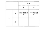
- the control unit is configured to detect the amount of microorganisms detected by the first detection device. Is greater than the threshold value and the second detection device detects that there is a person, the detection results of the first detection device, the detection results of the second detection device, which are stored in advance, And according to the correspondence of the drive of the adjustment device, the drive of the adjustment device is turned on, otherwise the drive of the adjustment device is turned off.
- the first detection device is a detection device for detecting microorganisms in the air
- the adjustment device is an air cleaner
- the control unit is configured to detect the amount of microorganisms detected by the first detection device. Is greater than the threshold value and the second detection device detects that there is a person, the detection results of the first detection device, the detection results of the second detection device, which are stored in advance,
- the driving amount of the adjusting device is set to an amount larger than the prescribed amount in accordance with the correspondence relationship of the driving of the adjusting device, and otherwise the driving amount of the adjusting device is set to an amount smaller than the prescribed amount.
- the control method is a control method for controlling an adjustment device including an adjustment mechanism for adjusting the state of air in the target space, and detects the state of air in the detection target space.
- Acquiring information including detection result input from a first detection device including a sensor for detecting and a second detection device including a sensor for detecting the presence or absence of a person in the detection target space; Controlling the adjusting device based on the information obtained.
- control device includes input information including a detection result from the first detection device including a sensor for detecting a state of air in the detection target space, and the detection target space.
- control device further includes a first communication unit for communicating with the first detection device and a second communication unit for communicating with the second detection device.
- control device stores a first acquisition unit for acquiring information for specifying the positions of the first detection device and the second detection device, and information for specifying an area serving as a control unit.
- a control unit for determining the content of the presentation based on a combination of the detection result from the first detection device and the detection result from the second detection device located in the same area. Includes a decision part.
- the determination unit stores the detection result of the first detection device, the presence / absence of a person as the detection result of the second detection device, and the position of the person detected by the second detection device, which are stored in advance.
- the content of the presentation is determined based on the correspondence between the combination of the distance between the position where the first detection device is installed and the content of the presentation, and the control unit is configured to detect the person detected by the second detection device.
- a process of calculating a distance between the position and the position where the first detection device is installed is further executed.
- the first detection device includes a plurality of sensors as sensors for detecting the state of air in the detection target space, and the detection result of the first detection device includes a plurality of sensors.
- a detection result is included, and the determination unit stores in advance a combination of a detection result of each of the plurality of sensors that is a detection result of the first detection device and a combination of the detection result of the second detection device.
- the content of the presentation is determined based on the correspondence with the content of the presentation.
- control unit executes information presentation for an area where the second detection device detects that a person is present.
- control device further includes a second acquisition unit for acquiring information specifying a position of the presentation device that presents the information, and the control unit is within a predetermined range from the person detected by the second detection device.
- the information is presented to the presentation device inside.
- the presenting method detects a first detection device including a sensor for detecting a state of air in the detection target space and the presence or absence of a person in the detection target space.
- the detection result from the first detection device and the second detection device A step of determining the content of the presentation based on the combination with the detection result, and a step of executing a process for causing the determined content to be presented.
- the air condition can be appropriately presented.
- FIG. 1 It is a figure which shows the specific example of a structure of the 1st example of a microbe sensor. It is a block diagram which shows the specific example of a function structure of the microorganisms sensor concerning a 1st example. It is a time chart which shows the flow of control in the measurement control part of an environment detection apparatus. It is a figure showing the specific example of the relationship between the variation
- FIG. 10 is a flowchart showing a flow of second display processing in the processing apparatus 300. It is a figure which shows the other example of the display with the processing apparatus concerning 2nd Embodiment. It is a figure which shows the specific example of the corresponding relationship required for the display of FIG. 32A. It is a figure which shows the other example of the display with the processing apparatus concerning 2nd Embodiment.
- FIG. 33A It is a figure which shows the specific example of the correspondence required for the display of FIG. 33A. It is a figure which shows the other example of the display with the processing apparatus concerning 2nd Embodiment. It is a figure which shows the specific example of the corresponding relationship required for the display of FIG. 34A. It is a figure which shows the other example of the display with the processing apparatus concerning 2nd Embodiment. It is a block diagram which shows the specific example of a function structure of the processing apparatus concerning 3rd Embodiment. It is a figure which shows the specific example of the corresponding
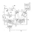
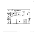
- FIG. 1 is a diagram showing a specific example of the configuration of an environment detection system (hereinafter abbreviated as system) 1 according to the present embodiment.
- system 1 includes a plurality of environment detection devices 100A, 100B,... For acquiring environment information connected by wired or wireless network 600, and attribute detection for detecting environment attributes.
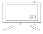
- the apparatus 200, the processing apparatus 300 provided with the display part, the adjustment apparatus 400 for adjusting an environment, and the display terminal 500 which has the display part 550 are included.
- the plurality of environment detection devices 100A, 100B,... Are representatively referred to as the environment detection device 100.
- the display terminal 500 may include a plurality of display terminals 500A, 500B,. In this case, the plurality of display terminals 500A, 500B,.
- the environment detection device 100 includes a plurality of sensors for acquiring environment information.
- Environmental information refers to information indicating the amount of parameters that determine the air condition in the space to be measured. For example, the amount of microorganisms in the air in the space to be measured, the amount of dust, humidity, temperature, and gas that causes odors Amount, etc. Therefore, as will be described later, the environment detection device 100 includes a microorganism sensor, a dust sensor, a humidity sensor, a temperature sensor, a gas sensor causing odor, and the like.
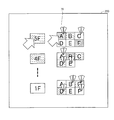
- the plurality of environment detection devices 100A, 100B,... are installed at various different positions. For example, in the case of a space having a plurality of rooms, it may be installed for each room, or in the case of a space having a plurality of floors, it may be installed for each floor.
- the environmental attribute indicates a parameter that affects the state of air in the space to be measured.
- the attribute detection device 200 includes a human sensor, a wind direction sensor, a wind sensor, and the like, which are an infrared sensor, an ultrasonic sensor, a visible light sensor, a pressure sensor, a temperature sensor, and the like.
- the environment attribute includes the position of the environment detection apparatus 100 in the target space.
- the environment detection apparatus 100 and the attribute detection apparatus 200 each have a communication function for performing wireless communication between them.
- This wireless communication corresponds to communication using radio waves such as Bluetooth (registered trademark) or WiFi (registered trademark), infrared communication, or the like.
- the attribute detection device 200 multicasts a response request within a predetermined communication range, and the environment detection device 100 within the communication range receives the response request and responds to it with identification information identifying itself. .
- the method of specifying the position of the environment detection device 100 using communication in the attribute detection device 200 is not limited to this method. Other methods may be adopted as long as the environment detection device 100 within the predetermined range is specified on the attribute detection device 200 side by establishing communication between these devices.
- the attribute detection device 200 detects the presence / absence / position of a person within the detection target range, the wind direction / volume, and the position of the environment detection device 100 as environmental attributes, and the processing device 300 as environmental attributes. Shall be sent.
- the processing device 300 identifies and stores the position where the attribute detection device 200 is installed by communicating with the attribute detection device 200 via the network 600.
- the position of the attribute detection device 200 is specified by using a service that provides position information using communication radio waves, such as GPS (Global Positioning System) or PlaceEngine (registered trademark), or image processing is performed.
- the position may be specified by specifying the identification image of the attribute detection device 200.
- the installation position may be registered in the processing apparatus 300 in advance. Note that the above-described position specifying method in the processing apparatus 300 is the same when specifying the position of another apparatus.
- the processing device 300 may be configured by any device as long as it includes at least a communication function, a display unit, and a computing device. As an example, it may be composed of a general personal computer.
- the processing device 300 receives a sensor signal from the environment detection device 100 via the network 600, and performs processing for displaying it on a display unit described later.
- the adjustment device 400 is a device for adjusting the amount of parameters that determine the air state of the target space, and corresponds to, for example, a humidifier / dehumidifier or an ion generator.
- the display terminal 500 may be any device as long as it has at least a display function and a communication function, and includes a mobile phone, an electronic book browsing terminal, a personal computer (PC), a television receiver, and the like.
- the processing device 300 communicates with each other via the display terminal 500 and the network 600 to identify and store the positions where they are installed.
- the installation position is a device that is fixed in principle, such as a television receiver
- the installation position may be registered in the processing device 300 in advance.
- the processing device 300 may store a correspondence relationship between the display terminal 500 and the user.
- the network 600 may be a network using communication using a dedicated line such as a local area network (LAN) or a wireless LAN, a network using communication using a public line such as the Internet, or wireless communication. For example, direct communication may be used.
- a dedicated line such as a local area network (LAN) or a wireless LAN
- a network using communication using a public line such as the Internet
- wireless communication For example, direct communication may be used.
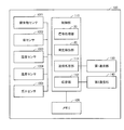
- FIG. 2 is a block diagram illustrating a specific example of the configuration of the environment detection apparatus 100.
- an environment detection apparatus 100 includes a microorganism sensor 1001, a dust sensor 1002, a humidity sensor 1003, a temperature sensor 1004, and a gas sensor 1005 as sensors for acquiring environment information, and a CPU (Central Processing Unit) (not shown). ), A control unit 110 for controlling the entire apparatus, a program executed by the CPU, a memory 120 for storing a sensor signal from the sensor, its own identification information, and the like, and others via the network 600 A first communication unit 130 for communicating with the first device, and a second communication unit 140 for wirelessly communicating with the attribute detection device 200. The detailed configuration of each sensor will be described later.
- control unit 110 of environment detection device 100 calculates signal processing unit 30 that is a function for processing signals from each sensor, and calculates a parameter amount to be detected based on the signals.
- the measurement detection unit 40 which is a function for executing the process, and the calculated parameter amount that is the detection result are processed as environment information together with its own identification information, name information, network address, and other attribute information.
- a transmission processing unit 111 that is a function for transmitting to the device 300 and a response for transmitting the identification information stored in advance in response to a request from the attribute detecting device 200 to the attribute detecting device 200 Part 112. These are functions mainly formed by the CPU by the CPU included in the control unit 110 reading and executing a program stored in the memory 120, but at least a part thereof is configured by hardware such as an electric circuit. May be.
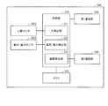
- FIG. 3 is a block diagram illustrating a specific example of the configuration of the attribute detection apparatus 200.
- the attribute detection device 200 is an infrared sensor, an ultrasonic sensor, a pressure sensor, or the like, and detects a human sensor 2001 for detecting the presence / absence of a person in a detection target region, and a wind direction and wind force.
- a first communication unit 230 for communicating with other devices via the network 600 and a second communication unit 240 for wirelessly communicating with the environment detection device 100 are included.
- the control unit 210 of the attribute detection apparatus 200 includes a person detection unit 211 that is a function for detecting the presence and position of a person based on a sensor signal from the human sensor 2001,
- the position of the environment detection device 100 is determined based on the communication result of the wind direction / wind force detection unit 212 and the second communication unit 240, which are functions for detecting the wind direction / wind force based on the sensor signal from the wind direction / wind force sensor 2002.
- a device detection unit 213 which is a function for detection.
- the human detection unit 211 identifies the relative position of the person from the position of the attribute detection device 200 based on the sensor signal from the human sensor 2001, and transmits it to the processing device 300 as an environmental attribute.
- the attribute detection apparatus 200 acquires its own position information using GPS, or acquires a position information using a service that provides position information using communication radio waves, such as PlaceEngine (registered trademark).
- PlaceEngine registered trademark
- the person detection unit 211 detects the person whose relative position is detected based on the position information of the person.
- the position information may be calculated and the position information may be used as the environment attribute.
- the device detection unit 213 is based on the communication result in the second communication unit 240, that is, when communication with the environment detection device 100 is established in the second communication unit 240, the communication strength in the second communication unit 240, etc.
- the position of the environment detection device 100 is specified based on the information, and the position is transmitted to the processing device 300 as an environment attribute together with the received identification information of the environment detection device 100.
- the attribute detection apparatus 200 stores its own position in advance
- the position of the environment detection apparatus 100 may be calculated from its own position, and the position information may be used as the environment attribute.
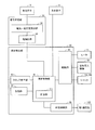
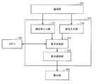
- FIG. 4A is a block diagram illustrating a specific example of the configuration of the processing apparatus 300.
- the processing device 300 is configured by a general personal computer. Therefore, it has a general personal computer configuration as shown in FIG. 4A.
- the processing device 300 includes a control unit 310 for controlling the entire device including a CPU (not shown), a program executed by the CPU, a sensor signal from the sensor, and display processing.
- a memory 320 for storing information and the like, a communication unit 330 for communicating with other devices via the network 600, and a display unit 350 are included.
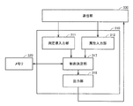
- FIG. 4B is a block diagram illustrating a specific example of the configuration of the adjustment device 400.
- the adjustment device 400 has, for example, a function for adjusting the temperature and humidity and a function for generating ions as a function for adjusting the amount of the parameter that determines the air state of the target space.
- adjustment device 400 is necessary for a control unit 410 for controlling the entire device including a CPU (not shown), and a program executed by the CPU and a sensor signal from the sensor and display processing.
- a memory 420 for storing information and the like, a communication unit 430 for communicating with other devices via the network 600, and an adjustment unit 460 are included.
- the adjustment device 400 has a function of generating ions, and the adjustment unit 460 is an ion generation unit. The detailed configuration of the adjustment unit 460 that is an ion generation unit will be described later.
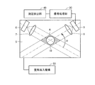
- FIG. 5 is a diagram illustrating a specific example of the configuration of the first example of the microorganism sensor 1001.
- the microorganism sensor 1001 according to the first example charges particles suspended in the air and adsorbs them to an electrode using an electrostatic force, and based on the difference in the amount of fluorescence before and after heating the electrodes, the microorganisms in the particles Is detected.
- a microorganism sensor 1001 has a case 5 provided with an introduction hole 10 and an exhaust hole 11 for introducing external air.
- An air introduction mechanism 50 for introducing air is included.
- the flow rate of the air introduced by the air introduction mechanism 50 is preferably 1 L (liter) / min to 50 m 3 / min.
- control unit 110 of the environment detection device 100 has a signal processing unit 30 that is a function for processing a signal from the microorganism sensor 1001, and a microorganism amount based on the signal.
- a measurement detection unit 40 that is a function for executing the processing to be calculated is included.
- the microorganism sensor 1001 includes a detection mechanism, a collection mechanism, and a heating mechanism.
- FIG. 5 shows an example of the collection mechanism including the discharge electrode 17, the collection jig 12, and the high-voltage power supply 2.
- the discharge electrode 17 is electrically connected to the negative electrode of the high voltage power source 2.
- the positive electrode of the high voltage power supply 2 is grounded.
- the collection jig 12 is a support substrate 4 made of a glass plate or the like having a conductive transparent film 3.
- the film 3 is grounded.
- the negatively charged airborne particles in the air move toward the collecting jig 12 by electrostatic force and are adsorbed by the conductive film 3 to be collected on the collecting jig 12.
- the detection mechanism includes a light-emitting element 6 that is a light source, a lens (or a lens group) 7 that is provided in the irradiation direction of the light-emitting element 6 and makes the light from the light-emitting element 6 parallel light or has a predetermined width.
- the aperture 13, the light receiving element 9 and the light receiving element 9 are provided in the light receiving direction of the light receiving element 9, and the fluorescence generated by irradiating the floating fine particles collected on the collecting jig 12 by the collecting mechanism from the light emitting element 6.
- 9 includes a condensing lens (or lens group) 8 for condensing light to 9 and a filter (or filter group) 14 for preventing irradiation light from entering the light receiving element 9.
- Conventional technology can be applied to these configurations.
- the light emitting element 6 includes a semiconductor laser or an LED element.
- the wavelength may be in the ultraviolet or visible region as long as it excites a microorganism to emit fluorescence.
- the wavelength is from 300 nm to 450 nm, which is contained in a microorganism and excites fluorescent tryptophan, NaDH, riboflavin, and the like efficiently.
- the heating mechanism includes a heater 91 that is electrically connected to the measurement detection unit 40 and whose heating amount (heating time, heating temperature, etc.) is controlled by the measurement detection unit 40.
- a ceramic heater is preferably used as the heater 91.
- FIG. 6A is a cross-sectional view of the microorganism sensor 1001 viewed from the AA position in FIG. 5 in the direction of the arrow
- FIG. 6B is a cross-sectional view viewed from the BB position in FIG. 6A in the direction of the arrow.
- these drawings do not show a collecting mechanism other than the collecting jig 12.
- light emitting element 6 and lens 7, light receiving element 9 and condenser lens 8 are provided at a right angle or a substantially right angle when viewed from the direction of arrow A (upper surface) in FIG.
- Reflected light from the irradiation region 15 formed on the surface of the collecting jig 12 from the light emitting element 6 through the lens 7 and the aperture 13 is directed in a direction along the incident light. Therefore, with this configuration, the reflected light does not directly enter the light receiving element 9.
- the arrangement is not limited to the illustrated arrangement as long as it is an arrangement that can prevent the reflected light and stray light from entering the light receiving element 9.
- the collection jig 12 has a configuration for collecting fluorescence from the particles collected on the surface corresponding to the irradiation region 15 in the light receiving element 9.
- This configuration corresponds to, for example, a spherical recess 51 with reference to FIG. 6B.
- the collection jig 12 is preferably provided so as to be inclined by an angle ⁇ in the direction toward the light receiving element 9 so that the surface of the collection jig 12 faces the light receiving element 9.
- the size of the recess 51 is not limited, but is preferably larger than the irradiation region 15.
- the light receiving element 9 is connected to the signal processing unit 30 and outputs a current signal proportional to the amount of received light to the signal processing unit 30. Therefore, the light emitted from the light-emitting element 6 by irradiating the particles floating in the introduced air and collected on the surface of the collecting jig 12 from the light-emitting element 6 is received by the light-receiving element 9. The amount of received light is detected by the signal processing unit 30.
- shutters 16A and 16B are installed in the introduction hole 10 and the discharge hole 11 of the case 5, respectively.
- the shutters 16A and 16B are connected to the measurement detection unit 40, and their opening and closing are controlled. By closing the shutters 16A and 16B, the inflow of air into the case 5 and the incidence of external light are blocked.
- the measurement detection unit 40 closes the shutters 16A and 16B during fluorescence measurement to be described later, and blocks the inflow of air into the case 5 and the incidence of external light. This interrupts the collection of suspended particles in the collection mechanism during fluorescence measurement.
- stray light in the case 5 can be suppressed by blocking external light from entering the case 5 during fluorescence measurement.
- either one of the shutters 16A and 16B for example, at least the shutter 16B of the discharge hole 11 may be provided.
- the detection principle in the microorganism sensor 1001 according to the first example will be described.
- fluorescence is emitted when a microorganism floating in the air is irradiated with ultraviolet light or blue light.
- fluorescent substances such as chemical fiber dust are floating in the air, and it can be distinguished whether it is from microorganisms or chemical fiber dust only by detecting the fluorescence. Not.
- the inventors performed heat treatment on each of microorganisms and dust of chemical fibers, and measured changes in fluorescence before and after heating. As a result, the fluorescence intensity of dust does not change by heat treatment. On the other hand, it was found that the fluorescence intensity of microorganisms increased by heat treatment. Therefore, in the microorganism sensor 1001 according to the first example, this phenomenon that the inventors have observed is applied as a detection principle.
- the fluorescence spectrum measured before heat treatment includes fluorescence from microorganisms and fluorescence from dust that emits fluorescence. Therefore, microorganisms cannot be detected separately from chemical fiber dust.
- the heat treatment only the microorganisms increase the fluorescence intensity, and the fluorescence intensity of the dust that emits fluorescence does not change. Therefore, the amount of microorganisms can be determined by measuring the difference between the fluorescence intensity before the heat treatment and the fluorescence intensity after the predetermined heat treatment.
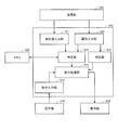
- FIG. 7 is a block diagram showing a specific example of a functional configuration of a microorganism sensor 1001 as a first example that detects microorganisms in the air using the above principle.
- the control unit 110 of the environment detection apparatus 100 includes the signal processing unit 30 and the measurement detection unit 40 as functions for processing a signal from the microorganism sensor 1001.
- FIG. 7 shows an example in which the function of the signal processing unit 30 is realized by a hardware configuration that is mainly an electric circuit. However, at least a part of these functions may be a software configuration realized by a CPU included in the control unit 110 executing a program stored in the memory 120.
- the configuration of the measurement detection unit 40 is a software configuration is shown. However, at least some of these functions may be realized by a hardware configuration such as an electric circuit.
- the signal processing unit 30 includes a current-voltage conversion circuit 34 connected to the light receiving element 9 and an amplification circuit 35 connected to the current-voltage conversion circuit 34.
- the measurement detection unit 40 includes a measurement control unit 41, a storage unit 42, and a clock generation unit 47. Further, the measurement detection unit 40 includes an external connection unit 46 for performing processing necessary for data exchange with other devices in the first communication unit 130, the shutters 16A and 16B, the air introduction mechanism 50, and the heater 91. And a driving unit 48 for driving the motor.
- the fluorescence from the particles in the irradiation region 15 is condensed on the light receiving element 9. .
- a current signal corresponding to the amount of received light is output from the light receiving element 9 to the signal processing unit 30.
- the current signal is input to the current-voltage conversion circuit 34.
- the current-voltage conversion circuit 34 detects the peak current value H representing the fluorescence intensity from the current signal input from the light receiving element 9, and converts it into the voltage value Eh.
- the voltage value Eh is amplified to a preset amplification factor by the amplification circuit 35 and output to the measurement detection unit 40.
- the measurement control unit 41 of the measurement detection unit 40 receives an input of the voltage value Eh from the signal processing unit 30 and sequentially stores it in the storage unit 42.
- the clock generation unit 47 generates a clock signal and outputs it to the measurement control unit 41.
- the measurement control unit 41 outputs a control signal for opening and closing the shutters 16A and 16B to the driving unit 48 at a timing based on the clock signal, and controls the opening and closing of the shutters 16A and 16B.
- the measurement control part 41 is electrically connected with the light emitting element 6 and the light receiving element 9, and controls those ON / OFF.
- the measurement control unit 41 includes a calculation unit 411.
- the calculation unit 411 an operation for calculating the amount of microorganisms in the introduced air is performed using the voltage value Eh stored in the storage unit. A specific operation will be described with reference to a time chart showing a flow of control in the measurement control unit 41 of FIG.
- the concentration of microorganisms in the air introduced into the case 5 is calculated as the amount of microorganisms.
- the measurement control unit 41 of the measurement detection unit 40 outputs a control signal to the drive unit 48 to drive the air introduction mechanism 50 when the measurement operation in the microorganism sensor 1001 starts. Further, the measurement control unit 41 outputs a control signal for opening (turning on) the shutters 16 ⁇ / b> A and 16 ⁇ / b> B to the drive unit 48 at time T ⁇ b> 1 based on the clock signal from the clock generation unit 47. Thereafter, at time T2 after time ⁇ T1 has elapsed from time T1, the measurement control unit 41 outputs a control signal for closing (OFF) the shutters 16A and 16B to the drive unit 48.
- the shutters 16A and 16B are opened from time T1 to time ⁇ T1, and external air is introduced into the case 5 through the introduction hole 10 by driving the air introduction mechanism 50. Particles in the air introduced into the case 5 are negatively charged by the discharge electrode 17, and due to the flow of air and the electric field formed between the discharge electrode 17 and the coating 3 on the surface of the collecting jig 12, It is collected on the surface of the collecting jig 12 for a time ⁇ T1.
- the shutters 16A and 16B are closed, and the air flow in the case 5 stops. Thereby, collection of the floating particles by the collection jig 12 is completed. This also blocks stray light from the outside.
- the measurement control unit 41 outputs a control signal for causing the light receiving element 9 to start receiving light (ON) at time T2 when the shutters 16A and 16B are closed. Further, at the same time (time T2) or at time T3 slightly delayed from time T2, a control signal for starting (ON) light emission to the light emitting element 6 is output. After that, at time T4 after the time ⁇ T2 that is a predetermined measurement time for measuring the fluorescence intensity from time T3, the measurement control unit 41 controls the light receiving element 9 to end (OFF) light reception, And the control signal for making the light emitting element 6 complete
- the measurement time may be set in advance in the measurement control unit 41, or input or changed by a signal received from another device by the first communication unit 130 via the network 600. It may be.
- irradiation from the light emitting element 6 is started from time T3 (or time T2).
- the light from the light emitting element 6 is applied to the irradiation region 15 on the surface of the collecting jig 12, and fluorescence is emitted from the collected particles.
- Fluorescence for a prescribed measurement time ⁇ T2 from time T3 is received by the light receiving element 9, and a voltage value corresponding to the fluorescence intensity F1 is input to the measurement detection unit 40 and stored in the storage unit 42.
- the light received from the reflection region (not shown) where the particles on the surface of the collecting jig 12 are not collected, which is emitted from a light emitting element (not shown) such as an LED provided separately, is received.
- Light may be received by an element (not shown), and F1 / I0 may be stored in the storage unit 42 using the received light amount as a reference value I0.
- the measurement control unit 41 outputs a control signal for starting (ON) heating of the heater 91 at time T4 (or time slightly delayed from time T4) when the light emission of the light emitting element 6 and the light reception of the light receiving element 9 are terminated. Output. Then, at time T5 after the elapse of time ⁇ T3, which is a predetermined heat treatment time for the heat treatment from the start of heating of the heater 91 (time T4 or a time slightly delayed from time T4), the measurement control unit 41 turns the heater 91 on. A control signal for finishing (OFF) heating is output.
- the heat treatment is performed on the particles collected in the irradiation region 15 on the surface of the collection jig 12 by the heater 91 from the time T4 (or a time slightly delayed from the time T4) to the heat treatment time ⁇ T3. .
- the heating temperature at this time is defined in advance.
- a predetermined heating amount is applied to the particles collected on the surface of the collection jig 12.
- the heat treatment time ⁇ T3 (that is, the heating amount) may also be set in advance in the measurement control unit 41 as in the case of the measurement time, or may be input by a signal received from another device, It may be changed.
- An air introduction mechanism 50 may be used for the cooling process, and in this case, external air may be taken in from an inlet (not shown in FIG. 5) provided with a separate HEPA (High Efficiency Particulate Air) filter. .
- a cooling mechanism such as a Peltier element may be used separately.
- the measurement control unit 41 outputs a control signal for ending the operation of the air introduction mechanism 50, and outputs a control signal for starting (ON) light reception by the light receiving element 9 at time T6. Further, at the same time (time T6) or at time T7 slightly delayed from time T6, a control signal for starting (ON) the light emitting element 6 to emit light is output. Thereafter, at time T8 after the measurement time ⁇ T2 has elapsed from time T7, the measurement control unit 41 causes the light receiving element 9 to end (OFF) light reception and the light emitting element 6 to end light emission (OFF). The control signal is output.
- the fluorescent light for the measurement time ⁇ T2 after the particles collected from the light emitting element 6 to the irradiation region 15 on the surface of the collecting jig 12 are heated for the time ⁇ T3 is received by the light receiving element 9. .
- the voltage value corresponding to the fluorescence intensity F2 is input to the measurement detection unit 40 and stored in the storage unit 42.
- the calculation unit 411 calculates the difference between the stored fluorescence intensity F1 and fluorescence intensity F2 as the increase amount ⁇ F.
- the increase amount ⁇ F is related to the amount of microorganisms (such as the number or concentration of microorganisms).
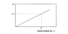
- the calculation unit 411 stores a correspondence relationship between the increase amount ⁇ F and the microorganism amount (concentration) as illustrated in FIG. 9 in advance. Then, the calculation unit 411 calculates the microbial concentration obtained using the calculated increase amount ⁇ F and the corresponding relationship as the microbial concentration in the air introduced into the case 5 during the time ⁇ T1.
- the correspondence between the increase amount ⁇ F and the microorganism concentration is experimentally determined in advance.
- one type of microorganism such as Escherichia coli, Bacillus or mold is sprayed using a nebulizer, and the microorganism concentration is maintained at N / m 3 , and the microorganism sensor 1001 Is used to collect microorganisms for a time ⁇ T1 by the above-described detection method.
- the microorganisms collected at a predetermined heating amount (heating time ⁇ T3, predetermined heating temperature) are subjected to heat treatment by the heater 91, and after cooling for the predetermined time ⁇ T4, the increase amount ⁇ F of fluorescence intensity before and after heating is measured.
- the same measurement is performed for various microorganism concentrations, whereby the relationship between the increase ⁇ F and the microorganism concentration (cells / m 3 ) shown in FIG. 9 is obtained.
- the correspondence between the increase amount ⁇ F and the microorganism concentration may be input from another device and stored in the calculation unit 411.
- the calculation unit 411 calculates the microorganism concentration N1 (pieces / m 3 ) by specifying a value corresponding to the increase amount ⁇ F1 from the correspondence relationship in FIG.
- the calculation unit 411 defines one of the microorganisms as a standard microorganism and stores the correspondence between the increase amount ⁇ F and the concentration of the microorganism.
- the microorganism concentration in various environments is calculated as a microorganism concentration converted with reference to the standard microorganism. As a result, various environments can be compared, and environmental management becomes easy.
- the increase ⁇ F uses the difference in fluorescence intensity before and after the heat treatment of a predetermined heating amount (predetermined heating temperature, heating time ⁇ T3), but these ratios are used. Also good.
- the concentration of the collected microorganisms calculated by the calculation unit 411 is transmitted to the processing apparatus 300 at a predetermined timing by the output process in the measurement control unit 41.
- the microorganism sensor 1001 according to the first example uses the difference in properties due to the heat treatment between the fluorescence from the microorganism and the fluorescence from the dust that emits the fluorescence, and based on the increase after the predetermined heat treatment, Is detected. That is, the microorganism sensor 1001 according to the first example detects microorganisms by utilizing the phenomenon that when the collected microorganisms and dust are heated, the fluorescence intensity of the microorganisms increases and the dust does not change. is there. For this reason, even when dust that emits fluorescence is contained in the introduced air, microorganisms can be separated and detected from dust that emits fluorescence in real time and with high accuracy.
- FIG. 10 is a diagram showing another specific example of the configuration of the microorganism sensor 1001 according to the first example.
- the detection mechanism and the collection mechanism may be provided in different spaces.
- a microorganism sensor 1001 includes a trapping mechanism including at least a part of a trapping mechanism separated by a wall 5C that is a partition wall having a hole 5C ′.
- a collection chamber 5A and a detection chamber 5B including a detection mechanism are provided.
- the collection chamber 5A is provided with a needle-like discharge electrode 17 and a collection jig 12 as a collection mechanism, and the detection chamber 5B has a light emitting element 6, a light receiving element 9, and a condenser lens 8 as a detection mechanism. Deployed.
- the discharge electrode 17 side and the collection jig 12 are respectively provided with an introduction hole 10 and a discharge hole 11 for introducing air into the collection chamber 5A.
- a fan 50A as an air introduction mechanism is provided in the vicinity of the discharge hole 11. Air from the suction port is introduced into the collection chamber 5A by the fan 50A.
- the drive mechanism of the fan 50A is controlled by the measurement detection unit 40, and the flow rate of the introduced air is controlled.
- the flow rate of the air introduced by the fan 50A is 1 L (liter) / min to 50 m 3 / min.
- the fan 50A is driven by a drive mechanism (not shown) controlled by the measurement detection unit 40, so that air outside the collection chamber 5A is collected from the introduction hole 10 through the collection chamber 5A as represented by a dotted arrow in the figure.
- the air in the collection chamber 5A is exhausted from the discharge hole 11 to the outside of the collection chamber 5A.
- airborne particles introduced from the introduction hole 10 by driving the fan 50A are negatively charged in the vicinity of the discharge electrode 17.
- the negatively charged particles move toward the collecting jig 12 by electrostatic force and are adsorbed by the conductive film, thereby being collected on the collecting jig 12.
- a light emitting element 6 and a light receiving element 9 are arranged in the detection chamber 5B.
- the light receiving element 9 is connected to the signal processing unit 30 and outputs a current signal proportional to the amount of received light to the signal processing unit 30. Therefore, the light emitted from the light-emitting element 6 by irradiating the particles floating in the introduced air and collected on the surface of the collecting jig 12 from the light-emitting element 6 is received by the light-receiving element 9. The amount of received light is detected by the signal processing unit 30.
- a brush 60 for refreshing the surface of the collecting jig 12 is provided at a position in the detection chamber 5B that touches the surface of the collecting jig 12.
- the brush 60 is connected to a moving mechanism (not shown) controlled by the measurement detection unit 40 and moves so as to reciprocate on the collecting jig 12 as indicated by a double-sided arrow B in the drawing. Thereby, dust and microorganisms adhering to the surface of the collecting jig 12 are removed.
- the unit including the collecting jig 12 and the heater 91 is referred to herein as a collecting unit 12A.
- the collection unit 12A is connected to a moving mechanism (not shown) controlled by the measurement detection unit 40, and as shown by a double-sided arrow A in the drawing, that is, from the collection chamber 5A to the detection chamber 5B, from the detection chamber 5B. It moves to the collection chamber 5A through the hole 5C ′ provided in the wall 5C.
- the heater 91 is a position where airborne particles collected on the collecting jig 12 can be heated, and at least when heated, sensor devices such as the light emitting element 6 and the light receiving element 9 are used. Therefore, it is not included in the collection unit 12A and may be provided at another position.
- the heater 91 when the heating operation is performed in the collection chamber 5A, the heater 91 is not included in the collection unit 12A, and is a position of the collection chamber 5A where the collection unit 12A is set, and a collection jig. 12 may be fixed to the side opposite to the sensor device such as the light emitting element 6 and the light receiving element 9. Even in this way, the heater 91 is separated from the sensor device such as the light emitting element 6 and the light receiving element 9 by the collecting jig 12 during heating, thereby suppressing the influence of heat on the light emitting element 6 and the light receiving element 9 and the like. be able to. In this case, at least the collection jig 12 may be included in the collection unit 12A.
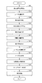
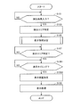
- the functional configuration of the microorganism sensor 1001 is the same as that shown in the block diagram of FIG. A specific measurement operation in the measurement control unit 41 will be described with reference to the flowchart of FIG.
- the concentration of microorganisms in the air introduced in the collection chamber 5A for a predetermined time is calculated as the amount of microorganisms.
- step S1 when microbial sensor 1001 is turned on, in step S1, the collection operation in collection chamber 5A is performed for a time ⁇ T1 that is a predefined collection time.
- the measurement control unit 41 outputs a control signal to the drive unit 48 to drive the fan 50A and take air into the collection chamber 5A. Particles in the air introduced into the collection chamber 5A are charged with a negative charge by the discharge electrode 17, and formed between the air flow by the fan 50A and the coating 3 on the surface of the discharge electrode 17 and the collection jig 12. Is collected in a narrow range corresponding to the irradiation region 15 on the surface of the collecting jig 12.
- the measurement control unit 41 ends the collection operation, that is, finishes driving the fan 50A.
- step S3 the measurement control unit 41 outputs a control signal to the drive unit 48 to operate a mechanism for moving the collection unit 12A, and detects the collection unit 12A from the collection chamber 5A. Move to chamber 5B.
- a detection operation is performed in step S5.
- the measurement control unit 41 causes the light emitting element 6 to emit light and causes the light receiving element 9 to receive the fluorescence for a predetermined measurement time ⁇ T2.
- the light from the light emitting element 6 is applied to the irradiation region 15 on the surface of the collecting jig 12, and fluorescence is emitted from the collected particles.
- a voltage value corresponding to the fluorescence intensity F ⁇ b> 1 is input to the measurement detection unit 40 and stored in the storage unit 42. Thereby, the fluorescence amount S1 before heating is measured.
- the measurement time ⁇ T2 may be set in advance in the measurement control unit 41, or may be input or changed from another device.
- the light received from the reflection region (not shown) where the particles on the surface of the collecting jig 12 are not collected, which is emitted from a light emitting element (not shown) such as an LED provided separately, is received.
- Light may be received by an element (not shown), and F1 / I0 may be stored in the storage unit 42 using the received light amount as a reference value I0.
- step S7 the measurement control unit 41 operates a mechanism for outputting a control signal to the drive unit 48 to move the collection unit 12A, and the collection unit 12A is moved.
- the detection chamber 5B is moved to the collection chamber 5A.
- step S9 similarly to the microorganism sensor 1001 according to the second example, the measurement control unit 41 causes the heater 91 to perform heating for a time ⁇ T3 which is a predetermined heat treatment time. The heating temperature at this time is defined in advance.
- step S11 the measurement control unit 41 outputs a control signal to the drive unit 48, and reversely rotates the fan 50A for a predetermined cooling time. It cools by making external air touch the collection unit 12A.
- the heat treatment time ⁇ T3, the heating temperature, and the cooling time may also be set in advance in the measurement control unit 41, or may be input and changed from another device.
- step S7 the collection unit 12A is moved to the collection chamber 5A, and then the heating operation and the cooling operation are performed in the collection chamber 5A.
- the collection unit 12A moves to the detection chamber 5B so
- the heater 91 is located at a distance from the sensor device such as the light emitting element 6 and the light receiving element 9 and is also separated by the wall 5C and the like, thereby suppressing the influence of heat on the light emitting element 6, the light receiving element 9 and the like. be able to.
- the heater 91 is in the collection chamber 5A separated from the sensor devices such as the light emitting element 6 and the light receiving element 9 by the wall 5C and the like at the time of heating as described above, the heater 91 is disposed in the collection unit 12A.
- the surface far from the discharge electrode 17, that is, the surface far from the light emitting element 6, the light receiving element 9, etc. when the collection unit 12 ⁇ / b> A moves to the detection chamber 5 ⁇ / b> B may not be present. It may be on the side.
- step S13 the measurement control unit 41 operates a mechanism for moving the collection unit 12A by outputting a control signal to the drive unit 48.
- the collection unit 12A is moved from the collection chamber 5A to the detection chamber 5B.
- the detection operation is performed again in step S15.
- the detection operation in step S15 is the same as the detection operation in step S5.
- the voltage value according to the fluorescence intensity F2 is input to the measurement detection unit 40 and stored in the storage unit 42. Thereby, the fluorescence amount S2 after heating is measured.
- step S17 When the fluorescence amount S2 after heating is measured in step S15, the refresh operation of the collection unit 12A is performed in step S17.
- step S ⁇ b> 17 the measurement control unit 41 outputs a control signal to the driving unit 48 to operate a mechanism for moving the brush 60, and reciprocates the brush 60 a predetermined number of times on the surface of the collection unit 12 ⁇ / b> A.
- step S19 the measurement control unit 41 outputs a control signal to the drive unit 48 to operate a mechanism for moving the collection unit 12A, and the collection unit 12A is moved to the detection chamber. Move from 5B to collection chamber 5A. Thereby, the next collection operation (S1) can be started immediately upon receiving the start instruction.
- the calculation unit 411 calculates the difference between the stored fluorescence intensity F1 and fluorescence intensity F2 as the increase amount ⁇ F. Then, in the same manner as the microorganism sensor 1001 according to the second example, the calculated increase amount ⁇ F and the correspondence relationship (FIG. 9) between the increase amount ⁇ F and the microorganism amount (concentration) stored in advance are obtained. The obtained microbial concentration is calculated as the microbial concentration in the air introduced into the collection chamber 5A during the time ⁇ T1. The calculated concentration of microorganisms in the collected particles is transmitted to the processing apparatus 300 at a predetermined timing by the output processing in the measurement control unit 41.
- the collection chamber 5A and the detection chamber 5B are separated, and the collection unit 12A moves back and forth between them to perform collection and detection. Collection and detection can be performed continuously.
- the collection jig 12 is heated and cooled in the collection chamber 5A as described above and is moved to the detection chamber 5B, the influence of heat on the sensors and the like in the detection chamber 5B can be suppressed. .
- microorganism sensor 1001 In the microorganism sensor 1001 according to the first example, airborne particles in the air are adsorbed and collected, and microorganisms are detected from the airborne particles based on the difference in the amount of fluorescence before and after heating.
- the method for detecting microorganisms from suspended particles is not limited to this method, and other methods may be used.
- Another example is a sensor that employs a method of detecting microorganisms from suspended particles using the difference in intensity of scattered light from suspended particles in the air. That is, the intensity of scattered light from airborne particles in the air depends on the size and refractive index of the airborne particles. Since microorganisms are filled with a liquid close to water, the microorganism can be approximated to transparent particles having a refractive index close to water.
- the microorganism sensor 1001 uses light of a dust particle of the same size when assuming that the refractive index of the microorganism floating in the air is a refractive index close to water. By utilizing the difference in scattering intensity at a specific scattering angle when irradiating, the microorganisms are separated from the suspended particles that are not, and detected.
- microorganisms at a predetermined scattering angle for example, 60 degrees
- a value between a scattering intensity from a particle having a refractive index of 1.3 (assuming a particle having a refractive index of 1.3) and a scattering intensity from dust (assuming a particle having a refractive index of 1.6) is stored.
- the microbial sensor 1001 measures the size and scattering intensity of the suspended particles in the introduced air, and stores the measured scattering intensity at the predetermined scattering angle in advance for the measured size.
- Microorganisms are detected from suspended particles by discriminating them as microbe particles when the boundary value is smaller than the boundary value and dust particles when the boundary value is larger.
- the size of the suspended particles in the air that is introduced is that the velocity of suspended particles in the air that is transported at a certain flow rate becomes slower if the size of the suspended particles increases if the air flow rate is not large. Can be detected. In other words, since the speed decreases as the size of the suspended particles increases, it can be used that the time that the suspended particles cross the irradiation light becomes longer.
- Scattered light generated by suspended particles carried at a certain flow velocity across the irradiation light from the light emitting element 6 is received by the light receiving element 9, and a pulsed current signal is output from the light receiving element 9. Is done.
- the pulse width is related to the time that the suspended particles cross the irradiation light. Therefore, the size of suspended particles is converted from the pulse width of the output current signal.
- the pulse width of the current signal from the light-receiving element 9 causes the outside air to flow into the microorganism sensor 1001 at a flow rate that is not too large so as to reflect the size of the suspended particles.
- FIG. 12 is a diagram showing a specific example of the configuration of the microorganism sensor 1001 according to the second example.
- the microorganism sensor 1001 according to the second example has a case 5 provided with an introduction hole 10 for introducing air from the suction port and an exhaust hole (not shown), and is introduced into the case 5.
- An air introduction mechanism 50 for introducing external air from the hole 10 is included.
- the flow rate of air introduced by the air introduction mechanism 50 is preferably 0.01 L (liter) / min to 10 L / min as a flow rate suitable for detecting the size of the above-mentioned suspended particles.
- a light emitting element 6 that is a light source
- a lens 7 that is provided in the irradiation direction of the light emitting element 6, makes the light from the light emitting element 6 parallel light or has a predetermined width, and a light receiving element 9.
- a condensing lens 8 for condensing the scattered light generated from the suspended fine particles present in the air by parallel light to the light receiving element 9.
- the fluorescence is cut before the condenser lens 8 or the light receiving element 9 so that the fluorescence from the microorganisms does not enter the light receiving element 9.
- An optical filter is installed.
- the light emitting element 6 and the lens 7, and the light receiving element 9 and the condensing lens 8 are respectively the irradiation direction of the light emitting element 6 made parallel light by the lens 7 and the light receiving element by being condensed by the condensing lens 8.
- the light receiving direction is set at a predetermined scattering angle ⁇ (for example, 60 degrees).
- the air moving from the introduction hole 10 to the discharge hole is condensed by the irradiation region from the light emitting element 6 which is converted into parallel light by the lens 7 and the light collecting element 8.
- 9 is installed at an angle so as to pass through the area A in FIG. 12, which is an area overlapping the area where light can be received.
- FIG. 12 shows an example in which these are installed so that the angle ⁇ is about 60 degrees and the region A is in front of the introduction hole 10.
- the angle ⁇ is not limited to 60 degrees and may be another angle.
- the light receiving element 9 is connected to the signal processing unit 30 and outputs a current signal proportional to the amount of received light to the signal processing unit 30.
- a current signal proportional to the amount of received light is emitted.
- the signal processing unit 30 is connected to the measurement detection unit 40 and outputs a result of processing the pulsed current signal to the measurement detection unit 40. Based on the processing result from the signal processing unit 30, the measurement detection unit 40 detects microorganisms from airborne particles in the air and performs processing for outputting the detection result.
- FIG. 13 is a block diagram showing a specific example of a functional configuration of a microorganism sensor 1001 as a second example that detects microorganisms in the air using the above principle.
- the control unit 110 of the environment detection apparatus 100 includes a signal processing unit 30 and a measurement detection unit 40 as functions for processing a signal from the microorganism sensor 1001.
- FIG. 13 shows an example in which the function of the signal processing unit 30 is realized by a hardware configuration that is mainly an electric circuit. However, at least a part of these functions may be a software configuration realized by a CPU included in the control unit 110 executing a program stored in the memory 120.
- the configuration of the measurement detection unit 40 is a software configuration is shown. However, at least some of these functions may be realized by a hardware configuration such as an electric circuit.
- signal processing unit 30 is connected to pulse width measuring circuit 32 connected to light receiving element 9, pulse width-voltage converting circuit 33 connected to pulse width measuring circuit 32, and light receiving element 9.
- a filter circuit 31 is provided between the light receiving element 9, the pulse width measurement circuit 32, and the current-voltage conversion circuit 34 for removing a signal having a preset current value or less. It is done. By providing the filter circuit 31, noise components due to stray light in the detection signal of the light receiving element 9 can be reduced.
- the measurement detection unit 40 includes a calculation unit 45, a storage unit 42, and an output unit 43 for outputting a detection result.
- a pulsed current signal corresponding to the amount of received light is output to the signal processing unit 30.
- the current signal is input to the pulse width measurement circuit 32 and the current-voltage conversion circuit 34 of the signal processing unit 30.
- a signal equal to or less than a preset current value is cut through the filter circuit 31.
- the current-voltage conversion circuit 34 detects the peak current value H representing the scattering intensity from the current signal input from the light receiving element 9, and converts it into the voltage value Eh.
- the voltage value Eh is amplified to a preset gain by the amplifier circuit 35 and output to the voltage comparison circuit 36.
- the pulse width measurement circuit 32 measures the pulse width W of the current signal input from the light receiving element 9.
- the method for measuring the pulse width or the value related thereto in the pulse width measuring circuit 32 is not limited to a specific method, and may be a well-known signal processing method. As an example, a measurement method when a differential circuit (not shown) is incorporated in the pulse width measurement circuit 32 will be described. That is, when a pulsed current signal is input, in the differentiating circuit, a constant voltage determined according to the first pulse signal is generated, and the voltage returns to 0 according to the next pulse signal.
- the pulse width measuring circuit 32 can measure the time from the rising edge to the falling edge of the voltage signal generated in the differentiating circuit and use it as the pulse width.
- the pulse width W may be a width between peaks of a differential curve obtained through a differentiating circuit.
- an interval of a half value of the peak voltage value of the pulse waveform that is, a half value width, or an interval from the rising edge to the falling edge of the pulse waveform may be used.
- a signal indicating the pulse width W measured by such a method or by another method is output to the pulse width-voltage conversion circuit 33.
- a voltage value Ew used as a boundary value of the scattering intensity for determining whether or not it is a microorganism is set in advance.
- the pulse width-voltage conversion circuit 33 converts the input pulse width W into a voltage value Ew according to the setting.
- the correspondence between the pulse width W and the voltage value Ew may be set as a function or a coefficient, or may be set in a table.
- the voltage value Ew is output to the voltage comparison circuit 36.
- the voltage value Ew which is a boundary value corresponding to the pulse width W, is experimentally determined in advance.
- a type of microorganism such as Escherichia coli, Bacillus or mold is sprayed into a 1 m 3 container using a nebulizer, and a pulse is generated from a current signal from the light receiving element 9 using a microorganism sensor 1001.
- the width and scattering intensity (peak voltage value) are measured.
- polystyrene particles having the same size are substituted for dust, and the pulse width and scattering intensity (peak voltage value) are measured using the microorganism sensor 1001.
- regions is determined from each area
- a voltage value Ew used as the boundary value determined in this way is set.
- the correspondence relationship between the pulse width W used as the boundary value and the voltage value Ew may be set by being input from another device.
- the correspondence relationship between the pulse width W and the voltage value Ew once set in the voltage comparison circuit 36 may be updated.
- the voltage comparison circuit 36 has a boundary value corresponding to the voltage value Eh representing the scattering intensity input from the current-voltage conversion circuit 34 via the amplification circuit 35 and the pulse width W input from the pulse width-voltage conversion circuit 33. Is compared with the voltage value Ew. Based on this comparison, the voltage comparison circuit 36 determines whether or not the suspended particles that generate the scattered light received by the light receiving element 9 are microorganisms.
- the determination by the voltage comparison circuit 36 is performed based on the scattered light from the particles every time the suspended light crosses the irradiation light from the light emitting element 6, and a signal indicating the determination result is output to the measurement detection unit 40.
- the calculation unit 45 of the measurement detection unit 40 receives an input of the determination result from the voltage comparison circuit 36 and sequentially stores it in the storage unit 42.
- the calculation unit 45 inputs the number of signals indicating a determination result that the detection target suspended particles are microorganisms and / or other determination results. This counts the number of times signals are input.
- the calculation unit 45 reads the flow rate of the introduced air from the air introduction mechanism 50 and multiplies the detection time to obtain the air amount Vs introduced into the case 5 during the detection time. As the detection result, the calculation unit 45 divides the number Ns of microorganisms or the number Nd of dust particles, which is the above-described total result, by the air amount Vs to obtain the concentration Ns / Vs of microorganisms or the concentration Nd / Vs of dust particles. .
- the number of microorganisms Ns and the number of dust particles Nd counted within the detection time, the calculated microorganism concentration Ns / Vs, and the dust particle concentration Nd / Vs, which are detection results, are stored in the storage unit 42. The Then, it is transmitted to the processing device 300 at a predetermined timing.
- a general gas sensor can be adopted.
- a semiconductor gas sensor such as SB-AQ1 manufactured by FIS can be used.
- a heater coil and an electrode lead wire are embedded in a gas-sensitive material obtained by adding a sensitizer to metal oxide secondary particles such as oxidized varnish (SnO 2 ) and sintering at high temperature.
- This gas sensitive element is mounted on a base with three electrode terminals, and is connected in series with the sensor resistance in a state where a constant voltage is applied to the heater to control the temperature of the gas sensitive element. Gas is detected by detecting a change in output voltage across the load resistor.
- Metal oxide crystals such as oxidized varnish adsorb oxygen on the surface in clean air and maintain a stable state.
- a reducing gas is present in the air, the adsorbed oxygen is reduced by reacting with oxygen and gas on the crystal surface, and as a result, electrons in the crystal are increased. Thereby, the resistance value of the metal oxide decreases.
- the gas sensor 1005 can detect the gas concentration in the air using the principle described above. In other words, when SB-AQ1 manufactured by FIS is used, the sensor resistance value decreases as the gas concentration increases, and is based on the change in output voltage across the load resistance connected in series with the sensor resistance. The gas concentration can be obtained by calculating the sensor resistance value. This detection value is also transmitted to the processing device 300 at a predetermined timing.
- the adjustment part 460 which is an ion part contained in the adjustment apparatus 400 is demonstrated.
- a configuration of a type that is used independently as an ion generator will be described as an example.
- a configuration as a part that is incorporated in the entire adjustment device 400 may be used.
- FIG. 14 is a diagram showing a specific example of the appearance of the adjustment unit 460 that is an ion generation unit.
- adjustment unit 460 that is an ion generation unit has a rectangular parallelepiped case with a hole cut, and a line for connecting to a DC power source of about 12 V (not shown) extends from the case.
- a plurality of holes are drilled, and a positive needle electrode 301A and a negative needle electrode 301B are positioned at the approximate center of each of the pair of holes.
- FIG. 15 is a diagram illustrating a specific example of a circuit configuration corresponding to a pair of holes of the adjustment unit 460 that is an ion generation unit.
- a plurality of circuit configurations shown in FIG. 16 are included in the adjustment unit 460 that is an ion generation unit.
- each circuit includes a conversion circuit for converting a direct current having a transistor and a piezoelectric element into an alternating current, and high voltage generation circuits 303A and 303B.
- FIG. 16 is a diagram showing a specific example of the circuit configuration on the positive electrode side in FIG.
- switch 302A when switch 302A is closed, a current from a DC power source of about 1.5V to 12V is converted to DC by a conversion circuit, rectified to the positive side by a diode, and then a high voltage is generated through a protection circuit.
- the high voltage generation circuit 303A includes a piezoelectric element, and generates a high voltage by boosting the input voltage rectified to the positive electrode side.
- the high voltage is supplied to the positive needle electrode 301A, and corona discharge occurs at the tip of the electrode 301A.
- positive ions are generated and discharged out of the case from the hole of the case of the adjustment unit 460 that is the ion generation unit provided with the electrode 301A.
- the positive ion is a cluster ion in which a plurality of water molecules are attached around a hydrogen ion (H + ), and is represented as H + (H 2 O) m (m is an arbitrary natural number).
- the negative ion is a cluster ion in which a plurality of water molecules are attached around an oxygen ion (O 2 ⁇ ), and is expressed as O 2 ⁇ (H 2 O) n (n is an arbitrary natural number).
- the switches 302A and 302B are connected to the control unit 410 of the adjustment device 400 and are turned ON / OFF by the control. When both switches are ON, positive and negative ions are released from the circuit, and when only one of the switches is ON, positive or negative unipolar ions are output from the circuit. Released. When both switches are OFF, no ions are released from the circuit.
- control unit 410 When functioning as a conventional ion generator, the control unit 410 turns on only one of the switches to generate unipolar ions such as negative ions from the circuit.
- 2- (H 2 O) n (n is an arbitrary natural number) is generated in an approximately equivalent amount, so that both ions surround airborne fungi and viruses in the air, and the active species produced at that time It is possible to remove floating fungi and the like by the action of hydroxyl radicals (.OH).
- the adjustment unit 460 which is an ion generation unit, is installed in the flow path on the downstream side of the filter. As a result, the generated ions ride on the air cleaned by the filter and are released from the exhaust port to the outside of the machine.
- the control unit 410 controls ON / OFF of the switches 302A and 302B in accordance with a control signal from the processing device 300 described later.
- the control signal from the processing apparatus 300 is a signal that generates a high concentration of ions for generating ions
- the switches of all the circuits included in the adjustment unit 460 that is an ion generation unit are turned on and lower than that.
- the switches of a predetermined number of circuits stored in advance are turned on and the switches of other circuits are turned off. By doing so, the ion concentration to be generated is controlled.
- the method for controlling the concentration of ions to be generated there is a method for controlling the ON / OFF intervals of the switches 302A and 302B.
- the ion concentration can be easily controlled.
- the environment detection devices 100 are installed at various positions, and the air state of the area is displayed for each predetermined area.
- the position where each environment detection apparatus 100 is installed is detected by the attribute detection apparatus 200, and information indicating the position of the environment detection apparatus 100 is sent from the attribute detection apparatus 200 to the processing apparatus 300 as an environment attribute.
- the processing device 300 the area where each environment detection device 100 is installed is specified based on the environment attribute from the attribute detection device 200. And the state of the air for every area is displayed based on the detection result from the environment detection apparatus 100 installed in the said area.
- This display process is hereinafter referred to as a first display process.
- the position where the user is located is detected by the attribute detection apparatus 200, and information representing the position where the user is located is sent from the attribute detection apparatus 200 to the processing apparatus 300 as an environmental attribute.
- the processing device 300 when the detection result of the environment detection device 100 is displayed, the air state of the area including the position where the user is present is displayed on the corresponding display terminal 500. This display process is hereinafter referred to as a second display process.
- the processing device 300 stores the position where the adjustment device 400 is provided in advance, and the adjustment device 400 arranged at a necessary position is controlled with a suitable control amount according to the detection result of the environment detection device 100. Control.
- the position of the adjustment device 400 may be detected by the attribute detection device 200 and sent to the processing device 300 in the same manner as the method of detecting the position of the environment detection device 100. This may be performed in parallel with the first display process or the second display process described above.
- FIG. 17 is a block diagram illustrating a specific example of a functional configuration of the processing device 300 for performing display control according to the first embodiment.
- Each function shown in FIG. 17 is mainly formed in the CPU by reading and executing a program stored in the memory 320 by the CPU included in the control unit 310 of the processing device 300.
- the unit may be realized by a hardware configuration such as an electric circuit.
- processing device 300 for performing display control inputs a measurement value and identification information of environment detection device 100 as environment information from environment detection device 100.
- a measurement value and identification information of environment detection device 100 as environment information from environment detection device 100.
- Attribute input unit 312 based on the input information, a specifying unit 313 for specifying the area where the environment detection apparatus 100 is installed, the area where the user is, and the like, and the display content are determined and displayed.
- areas that are display units are set in advance for the space to be detected, and the environment detection device 100 is arranged at various positions in the space.
- position information for each area is stored in a predetermined area of the memory 320 in advance.
- the position information is represented by latitude / longitude and the area that is the unit of display is a room
- the latitude / longitude for each room is stored in advance.
- the specifying unit 313 refers to the position information for each area stored in a predetermined area of the memory 320, and in which area the environment detection device 100 that has input the environment information is arranged, that is, the input detection result is Identify which area is the detection result. And the display process part 315 performs the process for displaying the state of air about the display target area based on the input detection result.
- the specifying unit 313 refers to the position information for each area stored in a predetermined area of the memory 320, and mutually stores the position where the attribute detection device 200 is stored in advance or the network 600. Based on the installation position of the attribute detection device 200 obtained by communication, in which area the attribute detection device 200 to which the environment attribute is input is arranged, that is, in which area the input environment attribute is Specify whether it is an attribute. Then, the display processing unit 315 further performs processing for displaying the air state for the display target area using the environment attribute.
- FIG. 18 is a flowchart showing the flow of the first display process in the processing apparatus 300.
- the operation shown in the flowchart of FIG. 18 is realized by causing the CPU included in the control unit 310 of the processing device 300 to read and execute a program stored in the memory 320 and to cause each unit shown in FIG. 17 to function. Is done.
- the CPU specifies a detection area of environment detection device 100 in step S103.
- the position information of the environment detection device 100 is previously acquired from the attribute detection device 200 together with the identification information of the environment detection device 100 and stored.
- the CPU calculates the position of the environment detection apparatus 100 based on the position information of the attribute detection apparatus 200 stored in advance, thereby the position information. To get.
- step S ⁇ b> 103 the CPU specifies the position information of the environment detection device 100 represented by the identification information input together with the detection result in step S ⁇ b> 101, and for each area stored in the position information and a predetermined area of the memory 320. By comparing the position information, the area where the environment detection apparatus 100 is installed is specified.
- step S105 the CPU determines the display mode for the area to be displayed based on the detection result of the area. That is, when the area where the environment detection apparatus 100 in which the detection result is input in step S101 is installed is a display target area, the display mode of the display target area is based on the detection result input in step S101. To decide. When there are a plurality of environment detection devices 100 installed in the display target area, the display mode of the display target area is determined based on the detection results of the plurality of environment detection devices 100. For example, the display mode of the display target area may be determined based on the value obtained by adding the detection results of the plurality of environment detection devices 100, or using a statistical value such as an average value thereof. The display mode of the display target area may be determined. The determination method here will be described later with a specific example.
- the CPU When the CPU receives designation of an area for displaying the detection result from the operation unit 370 (YES in step S107), the CPU executes a process for displaying the detection result of the area on the display unit 350. As a result, the detection result for the designated area is displayed on the display unit 350.
- FIG. 19 is a diagram illustrating a first specific example of a display screen in the first display process.
- a process for displaying the air state in the area is performed.
- the display processing unit 315 stores a reference value for dividing the bacteria into “high”, “low”, and “none” in advance, and compares the reference value with the detection value from the environment detection apparatus 100. By doing so, rank the amount of bacteria.
- the CPU stores the correspondence between the rank of the amount of bacteria and the display mode in advance.
- the display mode is hatched with diagonal lines when the amount of bacteria is “high” rank, hatched with a dotted horizontal line when rank is “low”, and no hatch when rank is “none”.
- An example in which is stored is shown.
- the display mode is not limited to hatching, and includes color, density, display size, a combination thereof, and the like.
- the display is not limited to the two-dimensional display and may be a three-dimensional display. In that case, the display mode includes a three-dimensional depth.
- the memory 320 stores the position information of areas A to F (or areas A to E) for each floor from 1F to 5F as areas that are display units in advance. ing. Then, by comparing with the position information of each environment detection device 100, the environment detection device 100 installed in the display target area is specified, and the amount of bacteria as a detection result from the environment detection device 100 is obtained. At this time, as described above, when a plurality of environment detection devices 100 are installed in the display target area, the amount of bacteria for the area is obtained based on the detection results of the plurality of environment detection devices 100. . And the display mode showing the state of the air of the said area is determined based on the quantity of the microbe.
- detection results for a wide range including a plurality of areas may be displayed. That is, as shown in FIG. 19, for each floor, the amount of bacteria on the floor based on the detection result for each area of the floor may be displayed.
- FIG. 20 is a diagram showing a second specific example of the display screen in the first display process.
- the button representing 5F is clicked, as shown by the arrow in FIG. 19, the display unit The screen displayed on 350 is represented.
- the arrangement and size of the area for each floor are stored in advance in the memory 320 as map information. Then, after determining the display range of the areas A to F of the 5F based on the map information, the display mode corresponding to the amount of bacteria in each area is determined.
- the state of the air in each area of the designated floor is displayed in a display mode according to the amount of bacteria detected in the display range according to the actual arrangement and size.
- the displayed example is shown.
- the state of air near each installation position is determined based on the detection result of each environment detection device 100 as a more detailed air state in the area. You may make it display.
- FIG. 21 is a diagram showing a third specific example of the display screen in the first display process, as indicated by an arrow in FIG. 19 or as indicated by an arrow in FIG. Further, a screen displayed on the display unit 350 when the button representing the area A on 5F is clicked is shown. It is assumed that two environment detection devices 100 are installed in area A on 5F.
- the air state based on the detection result of each environment detection device 100 installed in the area A of 5F is displayed in a position corresponding to each installation position according to the detection result. Is displayed.
- the CPU of the processing device 300 identifies each position of the environment detection device 100 in the area based on the position information of the environment detection device 100 and the position information of the area. And it displays in the display mode according to each detection result in the position according to the installation position of the environment detection apparatus 100 among the display range of the said area. By displaying in this way, the distribution of the air state in one area can be grasped at a glance.
- the adjustment device 400 is displayed together with the air state.
- the CPU of the processing device 300 specifies the position of the adjustment device 400 in the display target area based on the position information of the adjustment device 400 stored in advance. Then, a mark representing the adjustment device 400 is displayed at a position corresponding to the installation position of the adjustment device 400 in the display range of the area. The mark is a selectable mark.
- the CPU of the processing apparatus 300 accepts a control instruction to the adjustment apparatus 400 by accepting selection (clicking) of the mark. Become.
- an option for instructing the drive amount of the adjustment unit 460 of the adjustment device 400 is displayed on the display screen.
- driving amounts of “strong”, “medium”, “weak”, and “stop” are displayed.
- the user who sees the display of the air state can instruct the driving of the adjusting device 400 installed in the area.
- the adjustment device 400 is an ion generator and the air state in the area is a state where the amount of bacteria is “large”, the user can adjust the adjustment device 400 installed in the area or the bacteria It is possible to instruct the adjustment device 400 installed in the vicinity of the position where the amount is “large” to increase the air cleaning capability by setting the driving amount to “strong”.
- the air state in the area is a state where the amount of bacteria is “low” or “none”
- the user drives the adjustment device 400 installed in the area with “low”. Or can be instructed to stop driving. In this way, the optimum driving amount according to the displayed air condition can be obtained.
- the CPU of the processing device 300 controls the driving amount of the adjustment device 400 by accepting a selection operation from the user.
- the memory 220 of the processing device 300 adjusts the air state and adjustment in advance.
- the CPU is installed in the area based on the air state obtained from the detection result of the target area based on the correspondence relationship.
- the drive amount of the device 400 may be determined, and a control signal that will be the drive amount may be transmitted to the adjustment device 400.
- the air conditioner of each area is displayed, and the adjustment device 400 is automatically controlled so as to obtain a better air condition.
- the air state changes, the air state after the change is also displayed, and the user can confirm the effect of the control.
- the air state based on the amount of bacteria is displayed.
- the air state based on other parameters may be displayed, or the air state based on a combination of a plurality of parameters. May be displayed.
- FIG. 22 is a diagram showing a specific example of the display window 70 in the second display process.
- the air state is displayed based on the detection result from the microorganism sensor 1001 and the detection result from the dust sensor 1002 using a specific example substantially similar to the description of the first display process.
- display window 70 displayed in the second display process includes a mark 71 representing the air state based on the amount of bacteria, and environmental detection device 100 installed in the display target area.
- a mark 72 which is a meter representing the distance from the position to the user's position, a mark 73 representing the amount of dust, and a mark 74 for instructing the end of display of the display window 70 are displayed.
- the mark 71 is a mark imitating a human face, and the state of the air is expressed by its expression (smiling face, crying face, no expression, etc.).
- the mark 72 which is a meter represents the distance from the position of the environment detection apparatus 100 to the position of the user by the length of the meter.
- the mark 73 is a mark that represents each dust in a pseudo manner, and the amount of dust is expressed by the number.
- the predetermined area of the memory 320 stores in advance the correspondence between the amount of parameter represented by each mark and the state of the mark.
- 23A to 23C are diagrams showing specific examples of the correspondence relationship between the amount of parameter represented by each mark and the state of the mark.
- FIG. 23A is a correspondence relationship for displaying the mark 72
- FIG. FIG. 23C is a specific example of the correspondence for displaying 73 and FIG. 23C.
- the memory 320 stores the meter length corresponding to the rank of the distance from the position of the environment detection device 100 to the user's position as a correspondence relationship for displaying the mark 72. Yes.
- memory 320 stores the number of images presented as a pseudo representation of one dust corresponding to the dust amount rank, as a correspondence relationship for displaying mark 73.
- FIG. 23C in memory 320, as a correspondence relationship for displaying mark 71, a person corresponding to the rank of the amount of bacteria and the rank of the distance from the position of environment detection device 100 to the user's position is displayed. The expression of the mark imitating the face is stored.
- the specifying unit 313 of the processing device 300 for executing the second display processing receives the detection result of the microorganism sensor 1001 and the detection result of the dust sensor 1002 of the environment detection device 100, and ranks the amount of bacteria. , And rank the amount of dust. Further, the processing device 300 receives input of environmental attributes representing the position of the person detected by the attribute detection device 200 and the position of the environment detection device 100, calculates the distance between them, and divides the rank. The rank is the same as the rank in the first display process. Then, with reference to the correspondence relationships shown in FIGS. 23A to 23C stored in the memory 320, the marks 71, 72, and 73 for the display target area are specified.
- the specifying unit 313 of the processing device 300 for executing the second display process specifies the display terminal 500 that displays the air state.
- the processing device 300 communicates with each other via the network 600 to specify the position of each display terminal 500 and is stored in a predetermined area of the memory 320 in advance. Therefore, the specifying unit 313 specifies the display terminal 500 installed or positioned in the display target area, and specifies the display terminal 500 as the display terminal 500 that displays the air state.
- the specifying unit 313 may specify the display terminal 500 as the display terminal 500 that displays the air state by receiving a display request using the display terminal 500 from the user.
- FIG. 24 is a flowchart showing the flow of the second display process in the processing apparatus 300.
- the operation shown in the flowchart of FIG. 24 is realized by the CPU included in the control unit 310 of the processing device 300 reading and executing the program stored in the memory 320 and causing each unit shown in FIG. 17 to function. Is done.
- step S201 the CPU specifies the position of each environment detection device 100 based on the environment attribute from attribute detection device 200, and in step S203 specifies the position of the user.
- step S205 the CPU identifies the display terminal 500 that is closest to the position of the user as the display terminal 500 that displays the display window.
- step S207 the CPU specifies an area including the position where the user is present as an area to be displayed, and in step S209, specifies the environment detection apparatus 100 installed in the area.
- step S211 the CPU identifies the amount of bacteria and the amount of dust in the area based on the identified detection result from the environment detection apparatus 100.
- step S213 the CPU refers to the correspondence shown in FIG. 23B based on the specified dust amount, and determines the content of the mark 73, that is, the number of images presented in a pseudo manner representing one dust. To do.
- step S215 the CPU specifies a distance between them based on the specified position of the environment detection device 100 and the position of the user, and in step S217, based on this distance, the correspondence relationship shown in FIG. Referring to the content of the mark 72, that is, the length of the mark 72 as a meter is determined.
- step S219 the CPU refers to the correspondence shown in FIG. 23C based on the distance from the environment detection apparatus 100 to the user and the amount of the specified bacteria, that is, the content of the mark 71, that is, the person The facial expression of the mark that imitates the face is determined as the presentation content.
- step S221 the CPU generates display data for displaying the display window 70 based on the contents of the determined marks 71, 72, 73.
- step S223 a process for displaying the display window 70 based on the display data on the display terminal 500 specified in step S205 is executed.
- 25A and 25B are diagrams showing how the display window 70 is displayed on the specified display terminal 500.
- FIG. 25A and 25B are diagrams showing how the display window 70 is displayed on the specified display terminal 500.
- the display terminal 500A which is a television receiver
- the television receiver A display window 70 is displayed on a part of the display screen of the display terminal 500A.
- the display window 70 is displayed at a position and size that do not hinder the viewing of the program content displayed on the display terminal 500A, which is a television receiver.
- a mark indicating that display data for the display window 70 to be displayed is received is displayed, and the display window 70 is displayed by receiving a predetermined operation specified in advance. You may make it do.
- the display terminal 500B which is a mobile phone carried by the user or an electronic book viewing terminal
- the table shown in FIG. the display window 70 is displayed on a part of the display screen of the display terminal 500B which is a mobile phone or an electronic book browsing terminal.
- the display window 70 is displayed at a position and size that do not hinder the viewing of the content displayed on the display terminal 500B that is a mobile phone or an electronic book browsing terminal. .
- a mark indicating that display data for the display window 70 to be displayed is received is displayed, and a predetermined operation specified in advance is accepted.
- the display window 70 may be displayed.
- a mark indicating that display data is being received is displayed prior to display of the display window 70, so that other displays are temporarily terminated.
- a display window 70 can be displayed.
- the user can check the air condition in the area where he is in real time on the nearest display terminal.
- the air state based on each of the amount of bacteria and the amount of dust is displayed, but only one of them may be displayed, or the air state based on other parameters May be displayed, or an air state based on a combination of a plurality of parameters may be displayed.
- 26A and 26B are diagrams showing another specific example of the display window 70 in the second display process.
- a mark 75 representing the wind direction / air volume may be displayed.
- the mark 75 is an image of an arrow, and the direction represents the wind direction, and the size represents the air volume.
- the correspondence relationship between the wind direction / air volume and the direction and size of the mark is stored in advance, and the CPU of the processing device 300 represents an environment representing the wind direction / air volume from the attribute detection device 200. Based on the attribute, the correspondence relationship is referred to, and the content of the mark 75, that is, the direction and size of the mark 75 that is an arrow is determined.
- the wind direction and the air volume are displayed in consideration of the user position and the position of the environment detection apparatus 100.
- the straight line connecting the user position and the position of the environment detection device 100 is a reference axis and the wind direction is horizontal with respect to the reference axis
- the content of the mark 75 using the detected wind direction / wind force as it is, That is, the direction and size of the mark 75 that is an arrow is determined.
- the wind force (vector) is decomposed into a horizontal component and a vertical component with respect to the reference axis, and the content of the mark 75 for the horizontal component wind force, that is, an arrow.
- the size of the mark 75 is determined.
- the user can also check the state of the wind from the environment detection device 100 to his / her position, and can check the state of air in the direction toward himself / herself. it can.
- the display window 70 may be displayed three-dimensionally as shown in FIG. 26B. By displaying in this way, the user can grasp the state of air sensuously in relation to his / her position.
- the position of the environment detection apparatus 100 is dynamically acquired as an environment attribute. Therefore, even if the installation position of the environment detection device 100 is changed (moved), the position information (detection point) of the environment detection device 100 can be appropriately acquired, and an accurate display can be realized.
- the positional relationship between the user and the position (detection point) of the environment detection device 100 can be specified, the state of the air around the user is easily visible to the user. It can be presented at the terminal.
- the environment detection devices 100 are installed at various positions, and the air condition of the area is also determined using the presence / absence and distribution of people in the area for each predetermined area. Is displayed. In the following description, differences from the first embodiment will be particularly described.
- the attribute detection apparatus 200 uses a human sensor such as an infrared sensor, an ultrasonic sensor, a visible light sensor, or a pressure sensor, in addition to the presence or absence of a person in the space to be detected. The number of people in the space is also detected. Then, environment attributes representing them are sent to the processing device 300. For example, when a pressure sensor is used as the human sensor, the pressure sensor is installed on the floor of the space to be detected, and the human detection unit 211 sets the position where the pressure corresponding to the human weight is detected as the human position. And the number of places where pressure corresponding to the weight of the person is detected can be detected as the number of persons.
- a human sensor such as an infrared sensor, an ultrasonic sensor, a visible light sensor, or a pressure sensor
- the processing device 300 For example, when a pressure sensor is used as the human sensor, the pressure sensor is installed on the floor of the space to be detected, and the human detection unit 211 sets the position where the pressure corresponding to the human weight is detected as the
- the air state for each area is detected from the environment detection device 100 installed in the area.
- the first display process for displaying based on the above and the second display process for displaying on the corresponding display terminal 500 the air condition of the area including the position where the user is present are performed.
- FIG. 27 is a block diagram illustrating a specific example of a functional configuration of the processing device 300 for performing display control according to the second embodiment.
- Each of the functions shown in FIG. 27 is also mainly formed in the CPU by reading and executing a program stored in the memory 320 by the CPU included in the control unit 310 of the processing device 300.
- a part may be realized by a hardware configuration such as an electric circuit.
- a determination unit 316 is provided for determining the display timing based on the environmental attribute representing the presence or absence.
- the flow of the first display process in the processing device 300 is substantially the same as the flow of the first display process in the first embodiment shown in the flowchart of FIG.
- the CPU determines the display mode so that the number of people in each area represented by the environment attribute is also displayed in step S105.
- FIG. 28 is a diagram illustrating a first specific example of a display screen in the first display process.
- the air condition for each area of each floor shown in FIG. An example in which the presence or absence of people in the area is displayed is shown.
- FIG. 29 is a diagram showing a second specific example of the display screen in the first display process.
- the air state of each area of the floor designated as described above is in a display range according to the actual arrangement and size, in a display mode according to the detected amount of bacteria.
- an example is shown in which the presence / absence of persons in each area and the number of persons are displayed.
- the presence of a person is displayed using the mark 76 in the same manner as in FIG. 27, and the number of persons in the area is also displayed in the display range indicating the area where the person is detected.
- the presence / absence and number of people in each area can be grasped at a glance together with the positional relationship and size of each area, as well as the air condition of each area on the designated floor.
- FIG. 30 is a diagram showing a third specific example of the display screen in the first display process.
- the state of the air based on the detection result of each environment detection device 100 installed in the area A of 5F is displayed in a position corresponding to each installation position according to the detection result.
- an example in which the distribution of people in the area A on the 5th floor is displayed.
- a position where a person is present is represented by a black circle.
- the adjustment device 400 is displayed together with the air state and the human distribution, and an instruction for the control is accepted. May be.
- the user who saw the display of the air condition and the distribution of people can instruct the driving of the adjusting device 400 installed in the area in consideration of these.
- the adjustment device 400 is an ion generation device
- the air condition in the area is “high” in the amount of bacteria, and there are people in the vicinity
- the user adjusts the adjustment device installed in the area.
- the device 400 or the adjustment device 400 installed in the vicinity of the position where the amount of bacteria is “large” is instructed to increase the air cleaning capability by setting the driving amount to “strong”. be able to.
- the driving amount can be prevented from changing. In this way, it is possible to obtain an optimum driving amount in accordance with the displayed air state and human distribution.
- the CPU of the processing device 300 controls the driving amount of the adjustment device 400 by accepting a selection operation from the user.
- the CPU is based on the air condition and the human distribution obtained from the detection result of the target area based on the correspondence relationship. Then, the drive amount of the adjustment device 400 installed in the area may be determined, and a control signal that will be the drive amount may be transmitted to the adjustment device 400.
- the driving amount of the adjustment device 400 such as an ion generator can be automatically controlled to be a high driving amount when there is a person in the area or when there are more than a predetermined number of people.
- the adjustment device 400 is automatically controlled so as to obtain a better air condition in consideration of these.
- the air state changes, the air state after the change is also displayed, and the user can confirm the effect of the control.
- the air state based on the amount of bacteria is displayed.
- the air state based on other parameters may be displayed, or the air state based on a combination of a plurality of parameters. May be displayed.
- FIG. 31 is a flowchart showing the flow of the second display process in the processing apparatus 300. The operation shown in the flowchart of FIG. 31 is also performed by causing the CPU included in the control unit 310 of the processing device 300 to read out and execute a program stored in the memory 320 and to cause each unit shown in FIG. 27 to function. Realized.
- the flow of the first display process in the processing device 300 according to the second embodiment is the first display in the first embodiment shown in the flowchart of FIG. It is almost the same as the processing flow. Therefore, the difference in operation from the flowchart of FIG. 18 will be described.
- step S105 of the second display process the CPU, as in the first display process, for the area to be displayed, the detection result of the area, the presence / absence of the person represented as the environmental attribute of the area, and the person The display mode is determined based on the number of persons.
- the CPU when it is detected that there is a person in the area as the environmental attribute of the area, the CPU determines that it is the timing to display the detection result of the area. On the other hand, when it is detected that there is no person in the area as the environmental attribute of the area designated as the area to be displayed, it is determined that it is not time to display the detection result of the area.
- step S1061 If it is determined that the display timing has been reached (YES in step S1061), the CPU determines a display device for displaying the detection result of the area in step S1062, and the display device in which the detection result of the area is determined in step S108. Execute the process for displaying on the screen.
- the CPU determines that the display device 350 of the processing device 300 and the display terminal 500 included in the system 1 are display devices that display a display device with the user in the vicinity thereof.
- the position of the display terminal is detected and stored in the processing device 300 by communicating with each other via the network 600.
- the presence / absence of a person for each area is expressed as an environmental attribute of each area from the attribute detection device 200 and transmitted to the processing device 300. Therefore, the CPU of the processing device 300 compares these to determine whether there is a user in the vicinity of the display unit 350 of the processing device 300 and in the vicinity of each display terminal 500 included in the system 1.
- the display terminal 500 and / or the display unit 350 determined to be in the vicinity are determined as a display device that displays the detection result of the area.
- each display terminal 500 itself includes a human sensor such as an infrared sensor, and the detection result is transmitted to the processing device 300, whereby the processing device 300 identifies the display terminal 500 in which the user is in the vicinity. You may be able to do it.
- a human sensor such as an infrared sensor
- the detection result of the area determined to have a person is displayed, and the detection result of the area determined to have no person is not displayed. Further, it is displayed when the user is in the vicinity of the display terminal, and is not displayed when the user is not in the vicinity. For this reason, necessary information is displayed at a necessary timing, and efficient display is realized.
- the CPU of the processing device 300 may determine the display method in consideration of the positional relationship between the display terminal and the person and the state of the display terminal.
- the CPU of the processing device 300 calculates the distance between the position of the display terminal 500 determined to be displayed and the position of the detected person. If the distance is equal to or greater than a predetermined value, in addition to displaying the detection result Then, a control signal for notifying that the display is performed with sound or light may be transmitted to the display terminal 500. By doing so, it is possible to prompt the user who is slightly away from the display terminal 500 to confirm the display, thereby realizing more efficient display.
- a control signal for notifying that there is a detection result that is a display target by sound, vibration, lighting of a lamp, or the like may be transmitted to the display terminal 500.
- display data may be transmitted in response to a request from the display terminal 500.
- the CPU of the processing device 300 may determine the above-described sound, vibration, and lamp lighting mode according to the detection result. Specifically, when the amount of bacteria is “high” rank, or when the distance between the environment detection device 100 and the user is shorter than a predetermined distance, the sound is heard more than otherwise. It can be increased, vibration can be increased, the lamp lighting interval can be shortened, the amount of light can be increased, and the like. By doing in this way, a detection result can be generally grasped
- the detection result of the microorganism sensor 1001 among the microorganism sensor, dust sensor, humidity sensor, temperature sensor, and gas sensor provided in the environment detection apparatus 100 is displayed. That is, the display of the detection result by one type of sensor is described.
- a display method may be employed in which a plurality of parameters that are detection results of the sensors are combined and displayed.
- FIG. 32A shows a display example that displays the amount of bacteria detected by the microorganism sensor 1001 as three parameters. As an example, each of a plurality of colors (red, yellow, and blue) is lit in a single color. An example of displaying with a lamp to turn on is shown.
- a correspondence relationship between the amount of bacteria and the color of the lamp as shown in FIG. 32B is stored in advance.
- the amount of bacteria that is the detection result from 100 is compared with a threshold value, and the color of the lamp is determined with reference to the corresponding relationship.
- FIG. 33A shows an example in which the amount of bacteria detected by the microorganism sensor 1001 and other parameters are displayed as two parameters, and a display example of a combination of the amount of bacteria and humidity is shown as a specific example. Yes.
- This display shows the occurrence probability of mold, and indicates that the higher the meter (longer), the higher the probability of mold occurrence, and the lower (shorter) meter, the lower the probability of mold occurrence.
- a correspondence relationship between the combination of the amount of bacteria and the humidity and the height (length) of the meter as shown in FIG. 33B is stored in advance.
- the CPU refers to the correspondence relationship and determines the height (length) of the meter based on the combination of the amount of bacteria and the humidity that are detection results from the environment detection apparatus 100.
- FIG. 34A shows an example in which the amount of bacteria detected by the microorganism sensor 1001 and other parameters are displayed as two parameters, and a display example of a combination of the amount of bacteria and the amount of dust is shown as a specific example. It represents.
- This display indicates the quality (cleanliness) of the air in the space to be detected. The higher (longer) the meter, the higher the cleanness, and the lower (shorter) the meter, the lower the cleanness.
- a predetermined area of the memory 320 of the processing apparatus 300 has a correspondence relationship between the combination of the amount of bacteria and the amount of dust and the height (length) of the meter as shown in FIG. 34B in advance.
- the CPU determines the height (length) of the meter based on the combination of the amount of bacteria and the amount of dust that are detection results from the environment detection device 100 with reference to the correspondence.
- the correspondence between the combinations of the parameter amounts and the display contents is stored in advance in a predetermined area of the memory 320 of the processing device 300, and the CPU refers to the correspondence relationship to obtain the detection result from the environment detection device 100. This is realized by determining the display contents based on this.
- the display is not limited to the bar-shaped meter as shown in FIGS. 32A to 34B, but may be other shapes.
- an indicator as shown in FIG. 35 may be used, or a pie chart or a line chart may be used.
- the display form is not limited to the display, and an output form such as sound, light, and vibration may be used. In that case, the sound interval and volume, the light emission interval and the light emission amount, and the vibration interval Alternatively, the detection result may be output using a quantity or the like.
- the detection result can be displayed at an appropriate timing according to the display device that displays the detection result, the environmental attribute, and the detection result of the area, that is, the timing when there is a visible user.
- the user can be notified using an appropriate timing at which the state of the air around the user can be visually recognized and an appropriate display device that can be visually recognized.
- the processing device 300 controls the devices included in the system 1 according to the detection result in the environment detection device 100 and the position where the environment detection device 100 is installed. .
- the adjustment apparatus 400 that is an ion generation apparatus and the environment detection apparatus 100 correspond.
- FIG. 36 is a block diagram illustrating a specific example of a functional configuration of the processing device 300 for performing control according to the third embodiment.
- Each function shown in FIG. 36 is mainly formed in the CPU by reading and executing a program stored in the memory 320 by the CPU included in the control unit 310 of the processing device 300.
- the unit may be realized by a hardware configuration such as an electric circuit.
- processing device 300 for performing control accepts input of measurement values and identification information of environment detection device 100 as environment information from environment detection device 100. For receiving the input of information such as the presence / absence / position of a person within the detection target range, the wind direction / volume, and the position of the environment detection device 100 as environment attributes from the attribute detection device 200 and the measurement value input unit 311 Based on the attribute input unit 312 and the input information, a control determination unit 317 for determining the control content of the adjustment device 400 and the environment detection device 100 and a control signal corresponding to the control content are stored in advance. Or an output unit 318 for generating and executing processing for outputting the control signal from the communication unit 330 to the target device.
- a predetermined area of the memory 320 stores a correspondence relationship between a detection result, a device to be controlled, and its control content.
- the parameter used as the detection result may be a single parameter such as the amount of bacteria, or a combination of two or more parameters such as the amount of bacteria and humidity.
- the detection result may be a combination of environment information that is a detection result from the environment detection apparatus 100 and an environment attribute that is a detection result from the attribute detection apparatus 200.
- FIG. 37A and FIG. 37B are diagrams illustrating specific examples of the correspondence relationship between the detection result stored in the predetermined area of the memory 320, the device to be controlled, and the control content thereof.
- the correspondence relationship between the detection result and the control content of the adjustment device 400 when the adjustment device 400 that is an ion generator is a control target is defined.
- the adjustment device 400 is installed, as an example of controlling ON / OFF of a switch (not shown) of the adjustment device 400 that is an ion generator,
- the switch of the adjustment device 400 is turned on, that is, activated when the amount of bacteria is “large”, and is turned off under other conditions.
- adjustment device 400 As another example, there is a person in the area where adjustment device 400 is installed, as a device for controlling the driving amount (air volume) of adjustment device 400 that is an ion generator, and It is stipulated that the air volume is “strong” when the amount of bacteria is “large”, and the air volume is “weak” when the amount of bacteria is “low”.
- FIG. 38 is a flowchart showing the flow of the control operation in the processing device 300 according to the third embodiment.
- the operation shown in the flowchart of FIG. 38 is realized by causing the CPU included in the control unit 310 of the processing device 300 to read and execute a program stored in the memory 320 and to cause each unit shown in FIG. 36 to function. Is done.
- the CPU of processing device 300 accepts input of environment information that is a detection result from environment detection device 100 and environment attributes that are a detection result from attribute detection device 200 (step S301). Based on the correspondence relationship stored in the predetermined area of the memory 320, the device to be controlled and the control content are specified (step S303), and the control content determined for the device to be controlled is determined. A control signal for performing control is output (step S305).
- a detection result having a rank of “large” as the amount of bacteria is obtained as environmental information, and an environmental attribute indicating that there is a person in the area is obtained.
- the CPU turns on the adjustment device 400, which is an ion generator installed in the area, and outputs a control signal for starting the generation of ions to the ion generator.
- a control signal for setting the air volume from the adjustment device 400, which is an ion generator, to “strong” is output to the ion generator.
- the CPU of the processing device 300 communicates with the adjustment device 400 via the network 600 in step S303.
- the installation position of the adjustment device 400 obtained by performing is stored, and the adjustment device 400 to be controlled is specified based on the stored position of the adjustment device 400.
- the device to be controlled may be the environment detection device 100 as described above.
- the environment detection apparatus 100 has a moving mechanism (not shown).
- the moving mechanism for example, a wheel that moves on a rail provided in a room, a lift, or the like is applicable. This movement is performed according to a control signal from the processing device 300.
- the control of the environment detection device 100 for example, when the environment detection device 100 is not installed and the environment information is not obtained for an area where the presence of a person is detected as an environment attribute, the closest to the area For example, the environment detection device 100 installed at the position is specified, and the environment detection device 100 is moved to the area. By doing in this way, it becomes possible to automatically move the environment detection apparatus 100 to the area where the environment information is desired to be obtained, and to obtain the environment information of the area.
- ⁇ Effect of the third embodiment> By performing such control in the system 1 according to the third embodiment, based on the environment information that is the detection result in the environment detection device 100 and the environment attribute that is the detection result in the attribute detection device 200. Therefore, other devices in the corresponding area can be operated so that the air condition in the area is optimum, so that it is possible to detect the presence of a person without operating at unnecessary timing. It can be operated to make the environment clean.
- the message output destination is assumed to be the display unit 350 of the processing device 300.
- the terminal 500 may be used. Further, similarly to the above example, prior to display, it may be displayed by notifying that there is display data by light or sound, and receiving a predetermined operation.
- FIG. 39 is a block diagram illustrating a specific example of a functional configuration of the processing device 300 for performing the display processing according to the fourth embodiment.
- Each function shown in FIG. 39 is mainly formed in the CPU when the CPU included in the control unit 310 of the processing device 300 reads and executes a program stored in the memory 320.
- the unit may be realized by a hardware configuration such as an electric circuit.
- a processing device 300 for performing display processing inputs a measurement value and identification information of the environment detection device 100 as environment information from the environment detection device 100.
- a measurement value and identification information of the environment detection device 100 as environment information from the environment detection device 100.
- display determination unit 319 for determining message contents based on the input information
- display processing unit for executing processing for displaying the determined message on display unit 350 and the like 315.
- a predetermined area of the memory 320 stores a correspondence relationship between a combination of environment information and environment attributes, which are detection results, and message contents.
- the parameter used as the detection result may be a single parameter such as the amount of bacteria, or a combination of two or more parameters such as the amount of bacteria and humidity.
- the environment attribute parameter may also be a single parameter such as the presence or absence of a person, or a combination of two or more parameters such as the presence or absence of a person and the air volume.
- FIG. 40 is a diagram showing a specific example of a correspondence relationship between a combination of environment information and environment attributes stored in a predetermined area of the memory 320 and message contents.
- the environmental information includes a combination of a parameter of the amount of bacteria and other parameters (dust, pollen, smell, temperature, humidity, etc.), and environmental attributes such as human distribution (presence / absence) and A message corresponding to the combination with the distance to the environment detection apparatus 100 is defined.
- the detection result from the microorganism sensor 1001 of the environment detection apparatus 100 is a rank of “high” in the amount of bacteria, and from other sensors.
- the amount (the amount of dust, pollen, and gas) represented by the detection result is “large”, there is a person in the area, and the distance from the person's position to the position of the environment detection device 100 is greater than the specified distance. If it is too short (close), the message contents “Be careful about ambient air and be careful” and “Beware of germs / mold” are specified.
- the distance from the person's position to the position of the environment detection device 100 is longer (far) than the specified distance, the message content “There is a contaminated area in the room” is specified.
- the amount (the amount of dust, pollen, gas) represented by the detection results from other sensors is “low”, there is a person in the area, and the distance from the position of the person to the position of the environment detection device 100 Is shorter (closer) than the specified distance, the message content “Beware of germs / molds” is specified. Further, when the distance from the person's position to the position of the environment detection device 100 is longer (far) than the specified distance, the message content “There is a possibility of occurrence of germs / mold in the room” is specified. .
- the message content “Comfortable environmental condition” is specified.
- the message content “The indoor environment is a comfortable environment state” is specified.
- the temperature and humidity may be further used as environmental information parameters, and the message may be defined by a combination of the season and the like as other information.
- the message content is stored in a predetermined area of the memory 320 in advance, but may be input or changed by a predetermined operation.
- the CPU of the processing device 300 accepts input of environment information that is a detection result from the environment detection device 100 and an environment attribute that is a detection result from the attribute detection device 200, and based on them, a predetermined area of the memory 320
- the message content is specified with reference to the correspondence relationship stored in the message, and the process for displaying the determined message on the display unit 350 is executed.
- the CPU of the processing device 300 calculates the distance between them based on the position of the person detected by the attribute detection device 200 and the position of the environment detection device 100. Then, by comparing the distance with a threshold value stored in advance, it is determined whether the distance is “near” or “far”.
- the processing device 300 is installed in the vicinity of the position of the user detected by the environment detection device 100 by performing the same processing as the processing described in the second embodiment (or the relevant device).
- the display terminal 500 (which the user carries) may be specified, and a message may be displayed on the display terminal 500. In that case, as shown in the example of FIG. 40, when it is detected that there is no person in the display target area, the message may not be displayed.
- the position of the environment detection device 100 is detected by the attribute detection device 200 and sent to the processing device 300 as an environment attribute, and the positions of the attribute detection device 200 and the display terminal 500 are detected by the processing device 300. Yes.
- the attribute detection device 200 may detect the positions of the environment detection device 100, the attribute detection device 200, and the display terminal 500 and send them to the processing device 300.
- at least one of the environment detection device 100, the attribute detection device 200, and the display terminal 500 stores its own installed position, and the identification information for specifying the position together with its own identification information is a processing device. You may make it transmit to 300.
- identification information may be transmitted together with the detection result, for example, or may be transmitted in response to a request from the processing apparatus 300.
- the identification information for specifying the position is, for example, information (latitude / longitude, living room on the first floor, etc.) indicating a specific installed position, a network address for communication on the network 600, and the like. Also good.
- a program for causing a computer to execute the processing in the processing device 300 can also be provided.
- a program is a flexible disk attached to the computer, a CD-ROM (Compact Disk-Read Only).
- the program can be provided by being recorded on a computer-readable recording medium such as a memory (ROM), a read only memory (ROM), a random access memory (RAM), and a memory card.
- the program can be provided by being recorded on a recording medium such as a hard disk built in the computer.
- a program can also be provided by downloading via a network.
- the program according to the present invention is a program module that is provided as a part of a computer operating system (OS) and calls necessary modules in a predetermined arrangement at a predetermined timing to execute processing. Also good. In that case, the program itself does not include the module, and the process is executed in cooperation with the OS. A program that does not include such a module can also be included in the program according to the present invention.
- OS computer operating system
- the program according to the present invention may be provided by being incorporated in a part of another program. Even in this case, the program itself does not include the module included in the other program, and the process is executed in cooperation with the other program. Such a program incorporated in another program can also be included in the program according to the present invention.
- the provided program product is installed in a program storage unit such as a hard disk and executed.
- the program product includes the program itself and a recording medium on which the program is recorded.
Landscapes
- Chemical & Material Sciences (AREA)
- Life Sciences & Earth Sciences (AREA)
- Engineering & Computer Science (AREA)
- Health & Medical Sciences (AREA)
- Medicinal Chemistry (AREA)
- Food Science & Technology (AREA)
- Combustion & Propulsion (AREA)
- Physics & Mathematics (AREA)
- Analytical Chemistry (AREA)
- Biochemistry (AREA)
- General Health & Medical Sciences (AREA)
- General Physics & Mathematics (AREA)
- Immunology (AREA)
- Pathology (AREA)
- User Interface Of Digital Computer (AREA)
Abstract
La présente invention porte sur un dispositif de traitement, qui comprend ce qui suit : une unité d'entrée de valeur de mesure (311) pour recevoir une entrée de résultats de détection à partir d'un dispositif de détection qui comprend un capteur pour détecter la condition d'air ; une unité d'entrée d'attributs (312) pour recevoir une entrée d'attributs environnementaux qui comprennent une information spécifiant la position dans laquelle est installé le dispositif de détection ; et une unité de traitement d'affichage (315) pour provoquer un affichage par un écran d'affichage sur une unité d'affichage (350). L'unité de traitement d'affichage génère des données d'affichage pour l'écran d'affichage, qui affiche les résultats de détection en fonction de la position du dispositif de détection, et transmet les données d'affichage à l'unité d'affichage (350).
Applications Claiming Priority (8)
| Application Number | Priority Date | Filing Date | Title |
|---|---|---|---|
| JP2011-125083 | 2011-06-03 | ||
| JP2011125082A JP2012251889A (ja) | 2011-06-03 | 2011-06-03 | 制御装置および提示方法 |
| JP2011125083A JP2012251890A (ja) | 2011-06-03 | 2011-06-03 | 制御装置および提示方法 |
| JP2011-125085 | 2011-06-03 | ||
| JP2011125084A JP2012251732A (ja) | 2011-06-03 | 2011-06-03 | 制御装置および制御方法 |
| JP2011125085A JP2012251891A (ja) | 2011-06-03 | 2011-06-03 | 制御装置および提示方法 |
| JP2011-125082 | 2011-06-03 | ||
| JP2011-125084 | 2011-06-03 |
Publications (1)
| Publication Number | Publication Date |
|---|---|
| WO2012165558A1 true WO2012165558A1 (fr) | 2012-12-06 |
Family
ID=47259410
Family Applications (1)
| Application Number | Title | Priority Date | Filing Date |
|---|---|---|---|
| PCT/JP2012/064105 Ceased WO2012165558A1 (fr) | 2011-06-03 | 2012-05-31 | Dispositif de commande et procédé de présentation |
Country Status (1)
| Country | Link |
|---|---|
| WO (1) | WO2012165558A1 (fr) |
Cited By (4)
| Publication number | Priority date | Publication date | Assignee | Title |
|---|---|---|---|---|
| CN105180354A (zh) * | 2015-08-19 | 2015-12-23 | 朱正义 | 一种室内净化设备或调湿设备的智能开关 |
| CN107063951A (zh) * | 2015-11-10 | 2017-08-18 | Lg电子株式会社 | 浮游微生物检测装置 |
| US20230194489A1 (en) * | 2020-05-18 | 2023-06-22 | Ambisense Ltd. | Air quality monitoring device and system |
| EP4175684A4 (fr) * | 2020-07-01 | 2024-10-23 | Avid Business Pty Ltd (Acn: 083025003) As Trustee for Cedar Creek Trust | Dispositif de protection personnel portatif |
Citations (9)
| Publication number | Priority date | Publication date | Assignee | Title |
|---|---|---|---|---|
| JP2008075973A (ja) * | 2006-09-21 | 2008-04-03 | Toshiba Corp | 空調用センサーシステム |
| WO2008088020A1 (fr) * | 2007-01-17 | 2008-07-24 | Daikin Industries, Ltd. | Panneau de soufflerie de climatisation, système de commande de climatisation muni du panneau et procédé de commande de climatisation |
| JP2009103347A (ja) * | 2007-10-22 | 2009-05-14 | Yamaha Corp | 環境制御システム |
| JP2009257617A (ja) * | 2008-04-14 | 2009-11-05 | Daikin Ind Ltd | 空調システム及びその制御方法 |
| JP2010133665A (ja) * | 2008-12-05 | 2010-06-17 | Toshiba Corp | 空調監視制御システム |
| JP2010261643A (ja) * | 2009-05-01 | 2010-11-18 | Daikin Ind Ltd | 空調システム |
| JP2011021931A (ja) * | 2009-07-14 | 2011-02-03 | Sharp Corp | 微生物センサユニットおよび空気調和機 |
| JP2011027362A (ja) * | 2009-07-28 | 2011-02-10 | Mitsubishi Heavy Ind Ltd | 適応画面更新web空調監視装置及び方法並びにシステム |
| JP2011075133A (ja) * | 2009-09-29 | 2011-04-14 | Mitsubishi Electric Corp | 空調システム |
-
2012
- 2012-05-31 WO PCT/JP2012/064105 patent/WO2012165558A1/fr not_active Ceased
Patent Citations (9)
| Publication number | Priority date | Publication date | Assignee | Title |
|---|---|---|---|---|
| JP2008075973A (ja) * | 2006-09-21 | 2008-04-03 | Toshiba Corp | 空調用センサーシステム |
| WO2008088020A1 (fr) * | 2007-01-17 | 2008-07-24 | Daikin Industries, Ltd. | Panneau de soufflerie de climatisation, système de commande de climatisation muni du panneau et procédé de commande de climatisation |
| JP2009103347A (ja) * | 2007-10-22 | 2009-05-14 | Yamaha Corp | 環境制御システム |
| JP2009257617A (ja) * | 2008-04-14 | 2009-11-05 | Daikin Ind Ltd | 空調システム及びその制御方法 |
| JP2010133665A (ja) * | 2008-12-05 | 2010-06-17 | Toshiba Corp | 空調監視制御システム |
| JP2010261643A (ja) * | 2009-05-01 | 2010-11-18 | Daikin Ind Ltd | 空調システム |
| JP2011021931A (ja) * | 2009-07-14 | 2011-02-03 | Sharp Corp | 微生物センサユニットおよび空気調和機 |
| JP2011027362A (ja) * | 2009-07-28 | 2011-02-10 | Mitsubishi Heavy Ind Ltd | 適応画面更新web空調監視装置及び方法並びにシステム |
| JP2011075133A (ja) * | 2009-09-29 | 2011-04-14 | Mitsubishi Electric Corp | 空調システム |
Cited By (5)
| Publication number | Priority date | Publication date | Assignee | Title |
|---|---|---|---|---|
| CN105180354A (zh) * | 2015-08-19 | 2015-12-23 | 朱正义 | 一种室内净化设备或调湿设备的智能开关 |
| CN107063951A (zh) * | 2015-11-10 | 2017-08-18 | Lg电子株式会社 | 浮游微生物检测装置 |
| CN107063951B (zh) * | 2015-11-10 | 2020-06-16 | Lg电子株式会社 | 浮游微生物检测装置 |
| US20230194489A1 (en) * | 2020-05-18 | 2023-06-22 | Ambisense Ltd. | Air quality monitoring device and system |
| EP4175684A4 (fr) * | 2020-07-01 | 2024-10-23 | Avid Business Pty Ltd (Acn: 083025003) As Trustee for Cedar Creek Trust | Dispositif de protection personnel portatif |
Similar Documents
| Publication | Publication Date | Title |
|---|---|---|
| JP2012251889A (ja) | 制御装置および提示方法 | |
| JP2012251732A (ja) | 制御装置および制御方法 | |
| JPWO2011024672A1 (ja) | 表示制御装置 | |
| JP2012072946A (ja) | 空気調和機 | |
| JP5766736B2 (ja) | 空気中の生物由来の粒子を検出するための検出装置および検出方法 | |
| US10345216B2 (en) | Systems, devices, and methods for flow control and sample monitoring control | |
| JP2011097861A (ja) | 微生物検出装置および検出方法 | |
| JP2011083214A (ja) | 微生物検出装置および検出方法 | |
| CN113133315B (zh) | 降低室内氡浓度的通风系统 | |
| JP2012047427A (ja) | 空気清浄機および空気清浄機における表示方法 | |
| WO2012165558A1 (fr) | Dispositif de commande et procédé de présentation | |
| KR101971055B1 (ko) | 실내 공기질 관리 시스템, 실내 공기질 관리 방법 및 실내 공기질 관리를 제어하는 제어 장치 | |
| WO2016105555A1 (fr) | Systèmes et procédés de comptage de particules en suspension dans l'air portables | |
| WO2012165036A1 (fr) | Dispositif de détection et procédé de détection | |
| KR20200064957A (ko) | 라돈 저감을 위한 풍량 가변형 환기 시스템 | |
| JP2012251890A (ja) | 制御装置および提示方法 | |
| JP2012251891A (ja) | 制御装置および提示方法 | |
| WO2012029649A1 (fr) | Filtre à air, procédé d'affichage pour filtre à air et climatiseur | |
| JP2014092334A (ja) | 空気調和システム | |
| US20240361289A1 (en) | Systems and methods for analyzing air of an indoor environment | |
| KR102101711B1 (ko) | 라돈 저감을 위한 풍량 가변형 환기 시스템 | |
| JP2012127727A (ja) | 検出装置および検出方法 | |
| JP2011045547A (ja) | 電気掃除機 | |
| JP2022167708A (ja) | 微粒子計測器を用いた建物内空気浄化支援システム | |
| TW202507668A (zh) | 環境污染狀態通知系統 |
Legal Events
| Date | Code | Title | Description |
|---|---|---|---|
| 121 | Ep: the epo has been informed by wipo that ep was designated in this application |
Ref document number: 12792527 Country of ref document: EP Kind code of ref document: A1 |
|
| NENP | Non-entry into the national phase |
Ref country code: DE |
|
| 122 | Ep: pct application non-entry in european phase |
Ref document number: 12792527 Country of ref document: EP Kind code of ref document: A1 |