WO2012165631A1 - ジグソーパズルとその製造方法 - Google Patents
ジグソーパズルとその製造方法 Download PDFInfo
- Publication number
- WO2012165631A1 WO2012165631A1 PCT/JP2012/064324 JP2012064324W WO2012165631A1 WO 2012165631 A1 WO2012165631 A1 WO 2012165631A1 JP 2012064324 W JP2012064324 W JP 2012064324W WO 2012165631 A1 WO2012165631 A1 WO 2012165631A1
- Authority
- WO
- WIPO (PCT)
- Prior art keywords
- sheet
- jigsaw puzzle
- hard
- soft
- manufacturing
- Prior art date
- Legal status (The legal status is an assumption and is not a legal conclusion. Google has not performed a legal analysis and makes no representation as to the accuracy of the status listed.)
- Ceased
Links
Images





Classifications
-
- A—HUMAN NECESSITIES
- A63—SPORTS; GAMES; AMUSEMENTS
- A63F—CARD, BOARD, OR ROULETTE GAMES; INDOOR GAMES USING SMALL MOVING PLAYING BODIES; VIDEO GAMES; GAMES NOT OTHERWISE PROVIDED FOR
- A63F9/00—Games not otherwise provided for
- A63F9/06—Patience; Other games for self-amusement
- A63F9/10—Two-dimensional [2D] jig-saw puzzles
-
- B—PERFORMING OPERATIONS; TRANSPORTING
- B32—LAYERED PRODUCTS
- B32B—LAYERED PRODUCTS, i.e. PRODUCTS BUILT-UP OF STRATA OF FLAT OR NON-FLAT, e.g. CELLULAR OR HONEYCOMB, FORM
- B32B27/00—Layered products comprising a layer of synthetic resin
- B32B27/06—Layered products comprising a layer of synthetic resin as the main or only constituent of a layer, which is next to another layer of the same or of a different material
- B32B27/08—Layered products comprising a layer of synthetic resin as the main or only constituent of a layer, which is next to another layer of the same or of a different material of synthetic resin
-
- B—PERFORMING OPERATIONS; TRANSPORTING
- B32—LAYERED PRODUCTS
- B32B—LAYERED PRODUCTS, i.e. PRODUCTS BUILT-UP OF STRATA OF FLAT OR NON-FLAT, e.g. CELLULAR OR HONEYCOMB, FORM
- B32B27/00—Layered products comprising a layer of synthetic resin
- B32B27/30—Layered products comprising a layer of synthetic resin comprising vinyl (co)polymers; comprising acrylic (co)polymers
- B32B27/302—Layered products comprising a layer of synthetic resin comprising vinyl (co)polymers; comprising acrylic (co)polymers comprising aromatic vinyl (co)polymers, e.g. styrenic (co)polymers
-
- B—PERFORMING OPERATIONS; TRANSPORTING
- B32—LAYERED PRODUCTS
- B32B—LAYERED PRODUCTS, i.e. PRODUCTS BUILT-UP OF STRATA OF FLAT OR NON-FLAT, e.g. CELLULAR OR HONEYCOMB, FORM
- B32B27/00—Layered products comprising a layer of synthetic resin
- B32B27/30—Layered products comprising a layer of synthetic resin comprising vinyl (co)polymers; comprising acrylic (co)polymers
- B32B27/304—Layered products comprising a layer of synthetic resin comprising vinyl (co)polymers; comprising acrylic (co)polymers comprising vinyl halide (co)polymers, e.g. PVC, PVDC, PVF, PVDF
-
- B—PERFORMING OPERATIONS; TRANSPORTING
- B32—LAYERED PRODUCTS
- B32B—LAYERED PRODUCTS, i.e. PRODUCTS BUILT-UP OF STRATA OF FLAT OR NON-FLAT, e.g. CELLULAR OR HONEYCOMB, FORM
- B32B27/00—Layered products comprising a layer of synthetic resin
- B32B27/32—Layered products comprising a layer of synthetic resin comprising polyolefins
-
- B—PERFORMING OPERATIONS; TRANSPORTING
- B32—LAYERED PRODUCTS
- B32B—LAYERED PRODUCTS, i.e. PRODUCTS BUILT-UP OF STRATA OF FLAT OR NON-FLAT, e.g. CELLULAR OR HONEYCOMB, FORM
- B32B27/00—Layered products comprising a layer of synthetic resin
- B32B27/36—Layered products comprising a layer of synthetic resin comprising polyesters
-
- B—PERFORMING OPERATIONS; TRANSPORTING
- B32—LAYERED PRODUCTS
- B32B—LAYERED PRODUCTS, i.e. PRODUCTS BUILT-UP OF STRATA OF FLAT OR NON-FLAT, e.g. CELLULAR OR HONEYCOMB, FORM
- B32B3/00—Layered products comprising a layer with external or internal discontinuities or unevennesses, or a layer of non-planar shape; Layered products comprising a layer having particular features of form
- B32B3/02—Layered products comprising a layer with external or internal discontinuities or unevennesses, or a layer of non-planar shape; Layered products comprising a layer having particular features of form characterised by features of form at particular places, e.g. in edge regions
- B32B3/06—Layered products comprising a layer with external or internal discontinuities or unevennesses, or a layer of non-planar shape; Layered products comprising a layer having particular features of form characterised by features of form at particular places, e.g. in edge regions for securing layers together; for attaching the product to another member, e.g. to a support, or to another product, e.g. groove/tongue, interlocking
-
- A—HUMAN NECESSITIES
- A63—SPORTS; GAMES; AMUSEMENTS
- A63F—CARD, BOARD, OR ROULETTE GAMES; INDOOR GAMES USING SMALL MOVING PLAYING BODIES; VIDEO GAMES; GAMES NOT OTHERWISE PROVIDED FOR
- A63F9/00—Games not otherwise provided for
- A63F9/06—Patience; Other games for self-amusement
- A63F9/10—Two-dimensional [2D] jig-saw puzzles
- A63F2009/1072—Manufacturing
-
- A—HUMAN NECESSITIES
- A63—SPORTS; GAMES; AMUSEMENTS
- A63F—CARD, BOARD, OR ROULETTE GAMES; INDOOR GAMES USING SMALL MOVING PLAYING BODIES; VIDEO GAMES; GAMES NOT OTHERWISE PROVIDED FOR
- A63F9/00—Games not otherwise provided for
- A63F9/06—Patience; Other games for self-amusement
- A63F9/10—Two-dimensional [2D] jig-saw puzzles
- A63F2009/1083—Two-dimensional [2D] jig-saw puzzles having plural layers on top of each other
-
- B—PERFORMING OPERATIONS; TRANSPORTING
- B32—LAYERED PRODUCTS
- B32B—LAYERED PRODUCTS, i.e. PRODUCTS BUILT-UP OF STRATA OF FLAT OR NON-FLAT, e.g. CELLULAR OR HONEYCOMB, FORM
- B32B2274/00—Thermoplastic elastomer material
-
- B—PERFORMING OPERATIONS; TRANSPORTING
- B32—LAYERED PRODUCTS
- B32B—LAYERED PRODUCTS, i.e. PRODUCTS BUILT-UP OF STRATA OF FLAT OR NON-FLAT, e.g. CELLULAR OR HONEYCOMB, FORM
- B32B2307/00—Properties of the layers or laminate
- B32B2307/40—Properties of the layers or laminate having particular optical properties
- B32B2307/412—Transparent
-
- B—PERFORMING OPERATIONS; TRANSPORTING
- B32—LAYERED PRODUCTS
- B32B—LAYERED PRODUCTS, i.e. PRODUCTS BUILT-UP OF STRATA OF FLAT OR NON-FLAT, e.g. CELLULAR OR HONEYCOMB, FORM
- B32B2307/00—Properties of the layers or laminate
- B32B2307/50—Properties of the layers or laminate having particular mechanical properties
- B32B2307/51—Elastic
Definitions
- the present invention relates to a jigsaw puzzle and a method of manufacturing the same. More specifically, the present invention relates to a jigsaw puzzle formed of a synthetic resin laminate and a method of manufacturing the same.
- the jigsaw puzzle is formed by dividing a flat plate such as a flat paper on which a pattern such as a picture, a picture, a figure, a symbol, a character, and a character is drawn into a plurality of pieces.
- a jigsaw puzzle is a toy to enjoy by fitting pieces that have been separated once into pieces and restoring the pattern.
- Each piece is a rectangular flat plate such as a square, and the side surface thereof is formed with a substantially circular engaging male portion or female portion.
- the engaging male part of one piece can be fitted to the engaging female part of the other adjacent piece.
- the engagement female portion of one piece is engaged with the engagement male portion of the other adjacent piece.
- Adjacent pieces are formed in such a shape that the engaging male portion and the engaging female portion fit exactly. And, the shapes of the individual pieces are all formed so as to be slightly different from one another and not formed identically. For this reason, one piece can be fitted only to adjacent pieces.
- These jigsaw puzzles are mainly formed by drawing a pattern on a relatively thick flat member such as paper, cork, wood or the like. Recently, synthetic resin jigsaw puzzles have been produced and are becoming clearer, and more and more people can enjoy patterns as if over a stained glass.
- the jigsaw puzzle requires a predetermined thickness to maintain the assembled state.
- the base sheet made of synthetic resin which is at least the material of the jigsaw puzzle, needs to have a thickness of 1.0 to 2.0 mm or more.
- a conventional base sheet is a laminate in which a thin film on which a pattern is printed is bonded to a sheet having a predetermined thickness according to the dimensions of a completed jigsaw puzzle using an adhesive or the like.
- the applicant applies a printing process to a hard sheet of a predetermined size using a sheet-fed offset printing machine, and superimposes a thick sheet of synthetic resin using a soft sheet and an adhesive.
- a synthetic resin jigsaw puzzle manufactured by punching a substrate with a punching machine (see Patent Document 1).
- the puzzle substrate described in Patent Document 1 is formed by bonding an outer layer hard film printed on the front and back surfaces of an inner layer soft sheet with an adhesive.
- the puzzle substrate is formed such that the inner layer soft sheet and the outer layer hard films on the front and back sides are integrated, and is formed like a relatively thick single plate.
- the piece made of synthetic resin described in Patent Document 1 does not easily come off when properly fitted. In addition, the player can surely get a feeling of fit when correctly fitting the synthetic resin pieces. Furthermore, since the fitting sound is emitted when the synthetic resin pieces are properly fitted, the player can feel pleasure as well as a sense of accomplishment.
- the jigsaw puzzle described in Patent Document 1 has a multi-step manufacturing process, and the workability and productivity are not good.
- a step of forming a puzzle substrate for uniformly applying the adhesive to the inner layer soft sheet formed to a predetermined size, and the outer layer rigid according to the size of the inner layer soft sheet A process of laminating films one by one, heating and pressing to form a laminate, pressing the formed laminate to form a puzzle substrate, and punching a puzzle substrate with a punching machine, etc.
- the manufacturing process requires multiple steps.
- the manufacturing method of the jigsaw puzzle described in patent document 1 has to apply
- in order to solidify the adhesive uniformly it is necessary to make the temperature of the plate uniform and apply pressure uniformly, which takes time and effort.
- the jigsaw puzzle described in Patent Document 1 requires a large number of working steps, and also takes time and effort to manufacture, resulting in high manufacturing cost. That is, there is a problem that the workability and productivity are poor, and it is not suitable for mass production, and costs such as manufacturing cost and labor cost are required.
- a base sheet is manufactured by cutting a laminated sheet in which a plurality of synthetic resin sheets are laminated into a predetermined shape, and the base sheet is punched by a punching blade and divided into a plurality of small pieces.
- Jigsaw puzzle wherein the laminated sheet is formed by extruding into a sheet shape, and is formed on a soft synthetic resin soft sheet and the soft sheet, and the synthetic sheet is harder than the soft sheet. It is characterized in that it is made of a resin-made rigid sheet.
- the laminated sheet presses the unhardened soft sheet and the hard sheet in the uncured state not completely cured after the extrusion molding with a cylindrical pressure roller.
- a cylindrical pressure roller are characterized in that they are integrally bonded together.
- the hard sheet in the first invention or the second invention, is a first hard sheet to be bonded to one side of the soft sheet, and a second hard sheet to be laminated to the other side of the soft sheet. It is characterized by comprising a sheet.
- At least one member selected from the soft sheet, the soft sheet, the first hard sheet, and the second hard sheet is a transparent or translucent member through which light passes. It is characterized by being.
- the jigsaw puzzle of the fifth invention is characterized in that, in the third invention or the fourth invention, the first hard sheet and / or the second hard sheet have a pattern printed by a rotary printing machine.
- the soft sheet is made of one or more thermoplastics whose main component is selected from polypropylene, polyvinyl chloride, polyethylene, polystyrene and polyethylene terephthalate. It is characterized in that it is made of a synthetic resin and the minor component is made of at least one thermoplastic elastomer selected from an olefin thermoplastic elastomer, a styrene thermoplastic elastomer and a polyester thermoplastic elastomer.
- the hard sheet is composed mainly of one or more thermoplastic synthetic resins selected from polypropylene, polyvinyl chloride, polyethylene, polystyrene and polyethylene terephthalate. To feature.
- the jigsaw puzzle of the eighth invention is characterized in that, in the first to seventh inventions, the plurality of small pieces are closely fitted with each other by being elastically deformed.
- a method of manufacturing a jigsaw puzzle according to a ninth aspect of the present invention is a first step of manufacturing a soft sheet by extruding a synthetic resin melted by extrusion into a sheet shape, and a hard sheet made of synthetic resin harder than the soft sheet.
- the laminated sheet is integrally bonded by pressing the soft sheet and the hard sheet with a cylindrical pressure roller in the ninth process. It is characterized by being
- a manufacturing method of a jigsaw puzzle of the present invention 11 is characterized in that, in the present invention 10, the soft sheet is bonded to the hard sheet in a non-hardened state which is not completely cured after the extrusion molding.
- the hard sheet is laminated to a first hard sheet to be laminated to one surface of the soft sheet and to another surface of the soft sheet. It is characterized by comprising a second hard sheet.
- At least one member selected from the soft sheet, the first hard sheet and the second hard sheet is a transparent or translucent member transmitting light. It is characterized by being.
- the manufacturing method of the jigsaw puzzle of the invention 14 is characterized in that, in the invention 12 or 13, the first hard sheet and / or the second hard sheet is provided with a pattern printed by a rotary printing machine. .
- the jigsaw puzzle of the present invention and the manufacturing method thereof are capable of continuously manufacturing jigsaw puzzles by cutting and punching a laminate obtained by sticking and laminating a hard sheet to a soft sheet which has been extruded and pressed. Production can be facilitated and costs can be reduced. In addition, the manufacturing process is easy, simple and can be performed in a short time, and the manufacturing cost and the labor cost can be reduced.
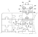
- FIG. 1 is a partial front view of a jigsaw puzzle to which the present invention is applied.
- FIG. 2 is a partial cross-sectional view of FIG. 1 cut along the line AA.
- FIG. 3 is a partial external view showing a state in which the piece 40 in FIG. 1 is removed.
- FIG. 4 is an enlarged partial sectional view showing how the piece 40 is fitted to the piece 30.
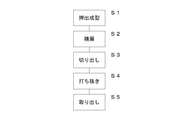
- FIG. 5 is a flow chart showing a manufacturing process of the jigsaw puzzle according to the manufacturing method 1 of the jigsaw puzzle of the present invention.
- FIG. 6 is a schematic view of a manufacturing line for manufacturing a jigsaw puzzle.
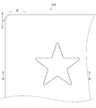
- FIG. 7 is a partial plan view of the base sheet.
- FIG. 1 is a partial front view of a jigsaw puzzle to which the present invention is applied.
- FIG. 2 is a partial cross-sectional view of FIG. 1 cut along the line AA.
- FIG. 3 is a partial external view showing a
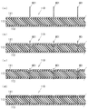
- FIG. 8 is a partial cross-sectional view showing the process of cutting the base sheet, taken along the line BB in FIG.
- FIG. 9 is a partial plan view of the base sheet after being cut.
- FIG. 10 is a partial cross-sectional view showing the process of cutting the base sheet, taken along the line CC of FIG.
- FIG. 1 is a partial front view of a jigsaw puzzle to which the present invention is applied.
- FIG. 2 is a partial cross-sectional view of FIG. 1 cut along the line AA.
- FIG. 3 is a partial external view showing a state in which the piece 40 in FIG. 1 is removed.
- FIG. 4 is an enlarged partial sectional view showing how the piece 40 is fitted to the piece 30. As shown in FIG.
- the arrow H direction is referred to as “longitudinal direction”, and the arrow S direction is referred to as “horizontal direction”.
- the arrow ⁇ direction indicating the thickness direction of the jigsaw puzzle is referred to as “upward”, and the arrow ⁇ direction is referred to as “downward”.
- a state in which one piece is fitted to another adjacent piece will be described as a “fitted state”.
- a state in which one piece is not fitted to an adjacent other piece will be described as "non-fitting state”.
- the jigsaw puzzle 1 is formed of a plurality of pieces. As shown in FIG. 1 or 2, the jigsaw puzzle 1 in the present embodiment is formed in a single flat plate having a predetermined thickness in a fitted state in which all the pieces are fitted. Each piece is rectangular and in the shape of a rectangular parallelepiped having a predetermined thickness, and is formed with an engaging male portion or an engaging female portion. In the present embodiment, the rectangular parallelepiped shape of each piece has dimensions of about 13 mm ⁇ 13 mm in length and width and a thickness as thin as 1.0 mm.
- each piece is formed with an engaging male portion (convex portion) or an engaging female portion (concave portion) for combining other pieces on its side surface.
- the piece 40 has a substantially rectangular parallelepiped shape, and two engaging male portions 40m and 40m 'and two engaging female portions 40f and 40f' are formed on the side surfaces thereof.
- the engaging male portion 40m is formed in a substantially cylindrical shape.
- the engaging male portion 40m is provided outward from one side surface 40a of the piece 40.
- a portion of the peripheral wall of the engaging male portion 40m is integrated with a portion of the side surface 40a.
- the engaging male portion 40m ' is formed to project from one side surface 40b in the same manner as the engaging male portion 40m.
- the engagement female portion 40 f is formed inward of the piece 40 from a predetermined position of one side surface 40 c of the piece 40.
- the engagement female portion 40 f is a substantially circular shaped circular hole formed penetrating from the front surface to the rear surface of the piece 40.
- the engagement female portion 40 f is formed by notching one side surface 40 c of the piece 40 in a bayonet shape.
- the engagement female portion 40f ' is formed on one side surface 40d similarly to the engagement female portion 40f.
- the mating male part of one piece can be fitted to the mating female part of the other piece.
- the engagement male portion 10m of the piece 10 can be fitted to the engagement female portion 40f of the adjacent piece 40.
- an adjacent piece engaging male portion is fitted to the engaging female portion of one piece.
- the engaging male portion 20m of the adjacent piece 20 is fitted to the engaging female portion 10f of the piece 10.
- Adjacent pieces are formed in a shape in which the engaging male portion and the engaging female portion fit snugly. And, the shapes of the individual pieces are all formed so as to be slightly different, and not to be identical pieces. That is, the engaging male portion and the engaging female portion of the non-adjacent pieces are formed so as not to be fitted tightly.
- patterns such as pictures, pictures, figures and characters are formed. The player can complete the jigsaw puzzle 1 by arranging the pieces one by one, relying on the shape of the pieces and the patterns drawn on the pieces separated.
- the engaging male portion or the engaging female portion is not formed on the side surface corresponding to the edge portion. Further, in the pieces constituting the four corners of the completed jigsaw puzzle, the engaging male portion or the engaging female portion is not formed on the two side surfaces corresponding to the corner portions.
- FIG. 2 is a cross-sectional view of FIG. 1 taken along the line AA, but in order to make it easy to understand its appearance, it is schematically shown with a thickness.
- each piece is formed of three layers of a first hard layer, a soft layer and a second hard layer.
- the pieces 20, 30, 40 are formed of the first hard layers 21, 31, 41, the soft layers 22, 32, 42 and the second hard layers 23, 33, 43. From the upper direction to the lower direction, each piece is formed so as to be stacked in order of each first hard layer, each soft layer and each second hard layer.
- each of the first hard layers is made of elastically deformable polypropylene.
- Each first hard layer is formed of a thin film of polypropylene of about 0.1 mm.
- Each first hard layer is formed to be harder than each soft layer.
- patterns such as pictures, photographs, figures and characters are given.
- the pattern of each first hard layer is printed by an offset rotary printing press or a gravure rotary printing press. In the present embodiment, a pattern is printed on the surface of each first hard layer, but a pattern may be printed on the back surface.
- Each soft layer is a composition in which an elastically deformable thermoplastic synthetic resin and a thermoplastic elastomer are blended.
- each soft layer is a composition in which polypropylene and a thermoplastic olefin elastomer are blended.
- Each soft layer is formed of a sheet about 0.8 mm thick. The soft layer is thicker than the first hard layer.
- Each soft layer is softer than each first hard layer and each second hard layer. That is, since each soft layer is a composition in which a thermoplastic synthetic resin is mixed with a thermoplastic elastomer, each soft layer is softer than each first hard layer and each second hard layer made of only a thermoplastic synthetic resin.
- each second hard layer is used for each second hard layer.
- Each second hard layer is formed of a thin film of polypropylene of about 0.1 mm.
- Each second hard layer is formed to be harder than each soft layer.
- no pattern is printed on each second hard layer. However, pattern printing may be performed on the front surface or the back surface of each second hard layer.
- each first hard layer, each soft layer, and each second hard layer are formed in a color with high transparency through light, but at least a part is a transparent or semi-transparent portion. It is good.
- Each piece is an integral laminate in which each first hard layer, each soft layer and each second hard layer are laminated in order.
- Each piece is formed by punching out a base sheet 110 which is a laminate integrally formed by pressing a first hard layer 111, a soft layer 112 and a second hard layer 113 described later with a pressure roller. It is done.
- each piece a soft soft layer is sandwiched between hard first hard layers and hard second hard layers, so that warpage is less likely to occur, and a firm structure can be maintained even if it is thin. Is formed.
- a member constituting each soft layer is a composition in which polypropylene and a thermoplastic olefin elastomer are mixed, and a member constituting each first hard layer and each second hard layer is made of polypropylene There is. As described above, each piece is formed so that the soft layer and the first hard layer and the second hard layer are made of the same kind of members, so that the adhesion is good and firmly integrated.
- a star-shaped pattern is printed on the jigsaw puzzle 1.
- This star-shaped pattern is printed by a gravure rotary printing press.
- a star-shaped pattern is formed over the pieces 10, 20, 30 and 40. The pieces 10, 20, 30 and 40 are fitted to form a star-shaped pattern.
- the side surface of the piece and the peripheral wall of the engaging male portion are formed in a plurality of arcuate shapes (hereinafter referred to as “ring-like shapes”) that continuously undulate in cross section.
- the side surface of each first hard layer is formed in a bow shape so as to project outward of the piece from the end of the surface of each first hard layer to the end of the back surface.
- the side surface of each first hard layer is formed to have a predetermined angle in a cross sectional view, an inclined surface having a predetermined dimension, an arc, a parabola, or the like.
- the side surface of each soft layer is formed in a bow shape so as to project outward of the piece from the end of the surface of each soft layer to the end of the back surface.
- the side surface of each soft layer is formed to have a predetermined angle in a cross sectional view, an inclined surface having a predetermined dimension, an arc, a parabola or the like.
- each second hard layer is formed in a bow shape so as to protrude outward of the piece from the end of the surface of each second hard layer to the end of the back surface.
- the side surface of each second hard layer is formed in a plane such as a predetermined angle, a predetermined angle of inclination, a circular arc or a parabola in a cross sectional view.
- the side surfaces of the piece 40 and the peripheral wall of the engaging male portion 40a are formed by forming the side surfaces of the first hard layers, the soft layers, and the second hard layers into an arc shape, respectively. It is in the form of mountains.
- a first arcuate side surface 41 a which is a side surface of the first hard layer 41 is formed in a bow shape so as to project outward of the piece from the end of the surface of the first hard layer 41 to the end of the back surface.
- the first arcuate side surface 41a is formed of a gutter surface, a shear surface and a burr surface.
- the gutter surface is formed to bow downward from the surface of each layer.
- the cross section is formed continuously below the gutter surface.
- the sheared surface is created by the cutting edge of the punched vertical blade 801 or the punched horizontal blade 802 biting.
- the punched section is a surface that is scraped and formed smoothly on the side surface of the punching vertical blade 801 or the punching horizontal blade 802.
- the burr surface is formed to project downward from the back surface of each layer.
- the burred surface is a surface of a burr formed when the punching vertical blade 801 or the punching horizontal blade 802 pierces through each layer.
- the side surface of the soft layer 42 is also a second arcuate side surface 42 a formed in the same manner as the first arcuate side surface 41 a. Furthermore, the side surface of the second hard layer 43 is also a third arcuate side surface 43a formed in the same manner as the first arcuate side surface 41a.
- Each arcuate side surface of the piece 40 is formed to project slightly outward from the contour of the surface of the piece 40.
- the side surface of the piece 30 and the inner diameter of the engagement female portion 30 f are formed in a chain shape.
- the side surface of the first hard layer 31 is also a first arcuate side surface 31 a formed in the same manner as the first arcuate side surface 41 a.
- the side surface of the soft layer 32 is also a second arcuate side surface 32 a formed in the same manner as the second arcuate side surface 42 a.
- the side surface of the second hard layer 33 is also a third arcuate side surface 33a formed in the same manner as the third arcuate side surface 43a.
- Each arcuate side of the piece 30 is formed to project slightly outward from the contour of the surface of the piece 30.
- Each arcuate side surface is formed to be elastically deformed when a predetermined force or more is applied.
- the side surface of the one piece and the side surface of the adjacent other piece are elastically deformed and in close contact with each other.
- FIG. 4 (d) shows that the engagement male portion 40m of the piece 40 is fitted to the engagement female portion 30f of the piece 30.
- the first arcuate side surface 41a of the engagement male portion 40m and the first arcuate side surface 31a of the engagement female portion 30f But they are elastically deformed and in close contact with each other.
- the imaginary lines 41c, 42c and 43c shown in FIG. 4 (a) are imaginary lines showing the positions when the arcuate side surfaces are elastically deformed when the engagement male portion 40m is fitted to the engagement female portion 30f.
- the imaginary line 41c is positioned when the first arcuate side surface 41a is elastically deformed to be in close contact with the first arcuate side surface 31a when the engagement male portion 40m is fitted to the engagement female portion 30f. It is an imaginary line to show.
- imaginary lines 42c and 43c are imaginary lines showing the positions of the second arcuate side surface 42a and the third arcuate side surface 43a when they are elastically deformed.
- the imaginary lines 31c, 32c and 33c are imaginary lines showing the positions of the first arcuate side surface 31a, the second arcuate side surface 32a, and the third arcuate side surface 33a when they are elastically deformed.
- Each arcuate side surface elastically deforms to the position of each imaginary line when a predetermined or more force is applied in the process of fitting the engagement male portion 40m to the engagement female portion 30f.
- the engagement male portion 40m and the engagement female portion 30f are in a fitted state in a state in which the respective arcuate side surfaces are elastically deformed and in close contact.
- the game player compares the pieces of the jigsaw puzzle 1 separated into pieces with the piece pattern to search for ones that are adjacent to each other. As shown in FIG. 4A, it is confirmed that one engaging male portion 40m of the piece 40 can be fitted to one engaging female portion 30f of the piece 30, and the back surface portion of the engaging male portion 40m is It matches with the opening part of engagement female part 30f.
- the engagement male portion 40m With the back surface portion of the engagement male portion 40m aligned with the opening portion of the engagement female portion 30f, the engagement male portion 40m is pressed downward. As shown in FIG. 4B, when the engaging male portion 40m is pressed, the third arcuate side surface 43a abuts on the first arcuate side surface 31a, and elastically deforms when reaching a predetermined force or more. At this time, the first arcuate side surface 31a is also elastically deformed. That is, the third arcuate side surface 43a elastically deforms to the position of the imaginary line 43c shown in FIG. 4 (a). The first arcuate side surface 31a is elastically deformed to the position of an imaginary line 31c shown in FIG. 4 (a). As shown in FIG. 4B, the elastically deformed third arcuate side surface 43a and the first arcuate side surface 31a are in close contact with each other.
- the engaging male portion 40m is further pressed downward.
- the third arcuate side surface 43a abuts on the second arcuate side surface 32a, and elastically deforms when reaching a predetermined force or more.
- the second arcuate side surface 32a is also elastically deformed.
- the second arcuate side surface 42a abuts on the second arcuate side surface 32a and the first arcuate side surface 31a, and elastically deforms when a predetermined force or more is reached.
- the second arcuate side surface 32a and the first arcuate side surface 31a are also elastically deformed. That is, the third arcuate side surface 43a elastically deforms to the position of the imaginary line 43c shown in FIG. 4 (a).
- the first arcuate side surface 31a is elastically deformed to the position of an imaginary line 31c shown in FIG. 4 (a).
- the second arcuate side surface 32a elastically deforms to the position of the imaginary line 32c shown in FIG. 4 (a).
- the third arcuate side surface 43a and the second arcuate side surface 32a are in close contact with each other, and the second arcuate side surface 42a includes the second arcuate side surface 32a and the first arcuate side surface 31a.
- the engaging male portion 40m is further pressed downward.
- the third arcuate side surface 43a abuts on the third arcuate side surface 33a, and elastically deforms when reaching a predetermined force or more. At this time, the third arcuate side surface 33a is also elastically deformed.
- the second arcuate side surface 42a abuts on the second arcuate side surface 32a, and elastically deforms when a predetermined force or more is reached. At this time, the second arcuate side surface 32a is also elastically deformed.
- the first arcuate side surface 41a abuts on the first arcuate side surface 31a, and elastically deforms when reaching a predetermined force or more. At this time, the first arcuate side surface 31a is also elastically deformed. That is, the third arcuate side surface 43a elastically deforms to the position of the imaginary line 43c shown in FIG. 4 (a).
- the first arcuate side surface 31a is elastically deformed to the position of an imaginary line 31c shown in FIG. 4 (a). Furthermore, the second arcuate side surface 32a elastically deforms to the position of the imaginary line 32c shown in FIG. 4 (a).
- each imaginary line is an imaginary line which shows the position when each arcuate side is elastically deformed.
- the position of this imaginary line is only an example, and it goes without saying that this position changes depending on the state of the force applied to the piece in the fitted state.
- FIG. 5 is a flow chart showing a manufacturing process of the jigsaw puzzle according to the manufacturing method 1 of the jigsaw puzzle of the present invention.
- FIG. 6 is a schematic view of a manufacturing line for manufacturing a jigsaw puzzle.
- FIG. 7 is a partial plan view of the base sheet.
- FIG. 8 is a partial cross-sectional view showing the process of cutting the base sheet, taken along the line BB in FIG.
- FIG. 9 is a partial plan view of the base sheet after being cut.
- FIG. 10 is a partial cross-sectional view showing the process of cutting the base sheet, taken along the line CC of FIG.
- the soft sheet 102 is extruded by the extruder 200 (S1).
- the first hard sheet 101, the soft sheet 102, and the second hard sheet 103 are laminated to produce the laminated sheet 100 (S2).
- the laminated sheet 100 is cut to manufacture a base sheet 110 (S3).
- the base sheet 110 is punched out to manufacture a jigsaw puzzle 1 (S4). Take out the jigsaw puzzle 1 (S5).
- the jigsaw puzzle 1 is completed.
- the specific manufacturing method will be described.
- the jigsaw puzzle 1 utilizes the extruder 200, the feeding device 300, 300 ′, the drawing rollers 401, 402, 403, the pressure bonding device 500, the adjusting device 600, the cutting device 700 and the punching device 800. Manufactured.
- the extruder 200 is an apparatus for forming the soft sheet 102 which becomes each soft layer of each piece of the jigsaw puzzle 1.
- the feeding device 300 is a device for rolling out the first roll 101r on which the first hard sheet 101 is wound.
- the feeding device 300 ′ is a device for rolling out the second roll 103 r on which the second hard sheet 103 is wound.
- the take-up rollers 401, 402, and 403 are rollers for taking each sheet.
- the pressure bonding apparatus 500 is an apparatus for manufacturing the laminated sheet 100 by laminating the first hard sheet 101, the soft sheet 102, and the second hard sheet 103.
- the adjusting device 600 is a device for adjusting the thickness of the laminated sheet 100 and eliminating warpage.
- the cutting device 700 is a device that cuts the laminated sheet 100 into a predetermined size to manufacture the base sheet 110.
- the punching apparatus 800 is an apparatus for manufacturing the jig sheet puzzle 1 by punching the base sheet 110 into pieces.
- the process of extrusion molding is a process of manufacturing a flexible sheet using the extruder 200.
- the material of the flexible sheet 102 is mainly a thermoplastic synthetic resin and a thermoplastic elastomer.
- thermoplastic synthetic resin any one or more of polyvinyl chloride, polypropylene, polyethylene, polystyrene and polyethylene terephthalate are used.
- Thermoplastic elastomers exhibit rubber elasticity at normal temperature, and have the property of being plasticized and able to be molded like thermoplastic resins at high temperatures.
- thermoplastic elastomer any one or more of an olefin-based thermoplastic elastomer, a styrene-based thermoplastic elastomer, a polyester-based thermoplastic elastomer, and the like are used.
- the extruder 200 is supplied with a thermoplastic resin composition comprising polypropylene and a thermoplastic olefin elastomer.
- the blending of polypropylene and thermoplastic elastomer may be appropriately adjusted in accordance with the color, pattern and hardness of the jigsaw puzzle.
- a heating cylinder After melting and kneading in a heating cylinder, it is extruded by means of a screw and given a sheet-like shape by a die 201 at the tip end.
- thermoplastic elastomer in addition to the olefin elastomer, a styrene elastomer or a polyester elastomer may be used.
- a thermoplastic olefin-based elastomer Thermo Chemical made by Mitsubishi Chemical Co., Ltd. or Zerus made by that company may be used.
- Lavalon manufactured by Mitsubishi Chemical Corporation may be used as the thermoplastic styrene-based elastomer.
- thermoplastic polyester-based elastomer Primaloy manufactured by Mitsubishi Chemical Co., Ltd. may be used.
- the soft sheet 102 is molded by the extruder 200 in an uncured state which is almost solid but not completely cured immediately after being extruded.
- the soft sheet 102 is formed into a transparent sheet. At this time, the soft sheet 102 is extruded at about 250 ° C.
- the soft sheet 102 is formed into a sheet having a predetermined thickness (for example, 0.8 mm) and a predetermined width (for example, 1200 mm) using a rolling roller.
- the soft sheet 102 is taken by the take-up roller 401 and moves to the pressure bonding device 500.
- the take-up roller 401 is composed of a drive roller that is rotationally driven and a nip roller (which may be rotationally driven or may be rotated according to the drive roller without being rotationally driven).
- the take-up rollers 402 and 403 described later have the same configuration.
- the soft sheet 102 is moved to the pressure bonding device 500 in the uncured state. At this time, the flexible sheet 102 is moved to the crimping device 500 within a temperature range of about 150 to 160.degree. That is, the soft sheet 102 is moved to the pressure bonding apparatus 500 at a lower temperature than immediately after being extruded by the extruder 200.
- the soft sheet 102 is naturally cooled by moving from the extruder 200 to the pressure bonding apparatus 500.
- the soft sheet 102 is moved from the extruder 200 to the crimping device 500 by one take-up roller 401.
- movement may be performed by a plurality of take-up rollers.
- a plurality of take-up rollers may be provided between the extruder 200 and the pressure bonding device 500 in the vertical direction.
- the soft sheet 102 can lower its temperature by a short distance by advancing in a zigzag manner through a plurality of take-up rollers provided at the upper and lower sides.
- the process of lamination is a process of laminating the first hard sheet 101, the soft sheet 102 and the second hard sheet 103 and manufacturing the laminated sheet 100 by the pressure bonding apparatus 500.
- the first hard sheet 101 is formed by printing a pattern on a transparent transparent film.
- the transparent film is made of elastically deformable polypropylene and is a thin film of about 0.1 mm.
- the first hard sheet 101 is prepared to have the same width (for example, 1200 mm) as the soft sheet 102.
- the first hard sheet 101 is formed by printing a predetermined pattern on a transparent film by a gravure rotary printing machine.
- the first hard sheet 101 has a plurality of identical patterns printed at predetermined intervals in the longitudinal direction.
- the first hard sheet 101 has a pattern printed on one side.
- the printed first hard sheet 101 is taken up by a take-up device and made into a first roll 101r.
- the first roll 101 r is installed in the feeding device 300.
- the feeding device 300 includes a reel stand (not shown) and an in-feed device 301.
- the reel stand supports the first roll 101r so as to be rotatable.
- the in-feed device 301 makes the tension and the speed of the first hard sheet 101 fed out from the first roll 101 uniform.
- the first hard sheet 101 is fed out from the first roll 101 r toward the crimping device 500 by the feeding device 300.
- the second hard sheet 103 is formed of a transparent film.
- the transparent film is made of elastically deformable polypropylene and is a thin film of about 0.1 mm.
- the second hard sheet 103 is prepared to have the same width (for example, 1200 mm) as the soft sheet 102.
- the second hard sheet 103 is taken up by a take-up device to form a second roll 103r.
- the second roll 103r is installed in the feeding device 300 '. Similar to the feeding device 300, the feeding device 300 'includes a reel stand (not shown) and an infeed device 301'.
- the second hard sheet 103 is fed out from the second roll 103r toward the crimping device 500 by the feeding device 300 '.
- the crimping device 500 is configured of a pair of crimping rollers 501 and 502.
- the pressure roller 501 is a roller that is rotationally driven.
- the pressure roller 502 may be a roller that is rotationally driven, or may be a roller that is rotated according to the pressure roller 501 without being rotationally driven.
- a nip portion is provided between the pair of pressure rollers 501 and 502 at a predetermined interval for passing the laminated sheet 100. In the present embodiment, the nip portions are formed at intervals of, for example, 1.0 mm.
- the first hard sheet 101 is aligned with one side of the soft sheet 102, and the second hard sheet 103 is aligned with the other side of the soft sheet 102 and guided to the nip portion. That is, the first hard sheet 101, the soft sheet 102, and the hard sheet 103 are guided to the nip portion in the order of being stacked from the top. In the state in which the first hard sheet 101, the soft sheet 102, and the hard sheet 103 are stacked in order, the thickness is 1.0 mm.
- the first hard sheet 101, the soft sheet 102, and the second hard sheet 103 are pressed at a predetermined pressure by passing through the nip portion in a laminated state, and a laminated sheet 100 having a thickness of 1.0 mm is manufactured. Ru. More specifically, the first hard sheet 101 and the second hard sheet 102 are pressurized at a predetermined pressure at the nip portion in a state in which the uncured soft sheet 102 is sandwiched. At this time, the soft sheet 102 in the uncured state is in a temperature range of about 150 ° C. to 160 ° C.
- the pressurized first hard sheet 101, the soft sheet 102, and the second hard sheet 102 are in close contact with each other.
- this close contact state when the temperature of the soft sheet 102 is lowered and it is completely cured, it becomes a laminated sheet 100 in which the first hard sheet 101, the soft sheet 102 and the second hard sheet are integrated. Therefore, the laminated sheet 100 is manufactured by integrally bonding the first hard sheet 101 and the second hard sheet 102 to the soft sheet 102 without requiring an adhesive or the like.
- the soft sheet 102, the first hard sheet 101, and the second hard sheet are made of the same kind of members, so they have good adhesion and are firmly integrated.
- the laminated sheet 100 since the soft flexible sheet 102 is sandwiched between the hard first hard sheet 101 and the hard second hard sheet 103, a warp or the like is less likely to occur, and a firm configuration can be maintained even if it is thin. It is formed in a sheet.
- the laminated sheet 100 is picked up by the pickup roller 402 and moved to the adjusting device 600.
- the adjusting device 600 includes adjusting rollers 601 and 602.
- the adjustment roller 601 is composed of a drive roller which is rotationally driven and a nip roller (which may be rotationally driven or may be rotated according to the drive roller without being rotationally driven).
- the adjustment roller 602 also has the same configuration.
- the adjustment roller 601 and the adjustment roller 602 are disposed at different heights.
- the adjustment roller 601 is disposed at a position higher than the take-up rollers 402 and 403.
- the adjustment roller 601 is disposed at a lower position than the take-up rollers 402 and 403.
- the laminated sheet 100 bends upward when passing through the adjustment roller 601 and moves while bending downward when passing through the adjustment roller 602.
- the laminated sheet 100 is adjusted to a flat plane free from warpage by reducing the internal stress by passing the adjusting rollers 601 and 602 arranged at different heights.
- the laminated sheet 100 which has passed through the adjusting device 600 is taken by the take-up roller 403 and moved to the cutting device 700.
- the laminated sheet 100 is cut into a rectangular shape of a predetermined size by the cutting blade 701 of the cutting device 700 to form the base sheet 110.
- the jigsaw puzzle of the present embodiment is cut out in a rectangular shape, it is needless to say that it may be cut out in another shape.
- the base sheet 110 is formed by integrating the first hard layer 111, the soft layer 112, and the second hard layer 113.
- the first hard layer 111 is obtained by cutting the first hard sheet 101.
- the soft layer 112 is obtained by cutting the soft sheet 102.
- the second hard layer 113 is obtained by cutting the second hard sheet 101.
- the base sheet 110 is punched by a punching device 800 to manufacture the jigsaw puzzle 1 composed of a plurality of pieces.
- the punching device 800 is provided with a punching vertical blade 801 and a punching horizontal blade 802.
- the punching vertical blade 801 and the punching horizontal blade 802 are blades for dividing the base sheet 110 into a plurality of pieces.
- the base sheet 110 is divided by the punching vertical blade 801 and the punching horizontal blade 802 to form an engagement male portion or an engagement female portion on each piece.
- a plurality of punching vertical blades 801 are provided at predetermined intervals so as to be substantially parallel to the longitudinal direction.
- a plurality of punching horizontal blades 802 are provided at predetermined intervals so as to be substantially parallel to the lateral direction.
- the base sheet 110 may be placed in a mold that matches the dimensions of the base sheet 110 so as not to shift in the process of being punched by the punched vertical blade 801 or the punched horizontal blade 802. Next, the process of forming the jigsaw puzzle 1 by punching out the base sheet 110 according to FIGS. 7 to 10 will be described in detail.
- the base sheet 110 has a pattern printed on its surface.
- the punching vertical blade 801 is first applied to the surface of the first hard layer 111.
- the punching vertical blade 801 is pressed downward while being in contact with the surface of the first hard layer 111.
- the first hard layer 111 elastically deforms when the punching vertical blade 801 is pressed with a predetermined force or more. At this time, a gutter surface is formed on the first hard layer 111.
- the punching vertical blade 801 punches the first hard layer 111.
- a sheared surface and a burred surface are formed on the first hard layer 111. The sagittal, shear and burr surfaces become the first arcuate side of each piece (see FIG. 4).
- the soft layer 112 elastically deforms when the punching vertical blade 801 is pressed with a predetermined force or more. At this time, a soft surface is formed on the soft layer 112. Furthermore, when the punching vertical blade 801 is pressed, the punching vertical blade 801 punches the soft layer 112. At this time, a shear surface and a burr surface are formed on the soft layer 112. The sagittal, shear and burr surfaces become the second arcuate side of each piece (see FIG. 4).
- the second hard layer 113 elastically deforms when the punching vertical blade 801 is pressed with a predetermined force or more. At this time, a gutter surface is formed on the second hard layer 113. Furthermore, when the punching vertical blade 801 is pressed, the punching vertical blade 801 punches the second hard layer 113. At this time, a shear surface and a burr surface are formed on the second hard layer 113. The sagittal, shear and burr surfaces become the third arcuate side of each piece (see FIG. 4).
- the punching vertical blade 801 is stopped at such a degree that the cutting edge slightly protrudes from the back surface of the second hard layer 113. Thereafter, the punching vertical blade 801 is moved upward and pulled out of the base sheet 110. At this time, the sheared surfaces of the first hard layer 111, the soft layer 112, and the second hard layer 113 are smoothed by scraping the punched vertical blade 801. As shown in FIG. 9, the base sheet 110 is cut in the longitudinal direction by being punched by the punching vertical blade 801.
- the punched horizontal blade 802 is applied to the surface of the first hard layer 111.
- the punching horizontal blade 802 is pressed downward while being in contact with the surface of the first hard layer 111.
- the first hard layer 111 is elastically deformed when the punching horizontal blade 802 is pressed with a predetermined force or more. At this time, a gutter surface is formed on the first hard layer 111.
- the punching horizontal blade 802 punches the first hard layer 111.
- a sheared surface and a burred surface are formed on the first hard layer 111. The sagittal, shear and burr surfaces become the first arcuate side of each piece (see FIG. 4).
- the soft layer 112 elastically deforms when the punching horizontal blade 802 is pressed with a predetermined force or more. At this time, a soft surface is formed on the soft layer 112. Furthermore, when the punching horizontal blade 802 is pressed, the punching horizontal blade 802 punches the soft layer 112. At this time, a shear surface and a burr surface are formed on the soft layer 112. The sagittal, shear and burr surfaces become the second arcuate side of each piece (see FIG. 4).
- the second hard layer 113 elastically deforms when the punching horizontal blade 802 is pressed with a predetermined force or more. At this time, a gutter surface is formed on the second hard layer 113. Furthermore, when the punching horizontal blade 802 is pressed, the punching horizontal blade 802 punches the second hard layer 113. At this time, a shear surface and a burr surface are formed on the second hard layer 113. The sagittal, shear and burr surfaces become the third arcuate side of each piece (see FIG. 4).
- the punching horizontal blade 802 is stopped at such an extent that the cutting edge slightly protrudes from the back surface of the second hard layer 113. Thereafter, the punching horizontal blade 802 is moved upward and pulled out of the base sheet 110. At this time, the sheared surfaces of the first hard layer 111, the soft layer 112, and the second hard layer 113 are smoothed by scraping the punched vertical blade 801. As shown in FIG. 1, the base sheet 110 is cut in the lateral direction by being punched by the punched horizontal blade 802, and the jigsaw puzzle 1 is completed.
- the pattern is printed on one side of the first hard sheet 101, but the pattern may be printed on the other side. That is, it goes without saying that the pattern may be printed on one side and / or the other side.
- the second hard sheet 103 is not printed with a pattern, but may also be printed with a pattern on one side and / or the other side.
- each piece is not limited to the present embodiment, and may have a thickness of 0.8 to 2.0 mm, and the thickness of each of the first hard layer, the second hard layer, and the soft layer may be appropriately changed accordingly Good.
- each first hard layer and each second hard layer may have a thickness of 0.1 to 0.2 mm, and the soft layer may have a thickness of 0.6 to 1.6 mm.
- the design may be improved by inserting metal pieces, beads, gems, lams and the like in the jigsaw puzzle.
Landscapes
- Engineering & Computer Science (AREA)
- Multimedia (AREA)
- Toys (AREA)
Abstract
製造が容易で簡便かつ短時間で製造され、製造コストの削減が図れるジグソーパズルとその製造方法の提供。 複数の合成樹脂製のシートが積層された積層シートを打ち抜き刃で打ち抜いて複数の小片に分けて形成されるジグソーパズルであって、前記積層シートは、押出成形でシート状に押し出されて形成される、軟質な合成樹脂製の軟質シートと、前記軟質シートに貼り合わせ、前記軟質シートに比べ硬質な合成樹脂製の硬質シートとからなることを特徴とするジグソーパズル。
Description
本発明は、ジグソーパズルとその製造方法に関する。更に詳しくは、合成樹脂の積層体で形成されたジグソーパズルとその製造方法に関する。
ジグソーパズルは、絵画、写真、図形、記号、文字及びキャラクター等の模様が描かれた平らな紙等の平板が複数のピースに分けられて形成されている。ジグソーパズルは、一旦バラバラに分離したピースを、嵌め合わせてその模様を復元することにより、楽しむ玩具である。各ピースは、四角形等の多角形の平板であり、その側面に略円形形状の係合雄部または係合雌部が形成されている。一のピースの係合雄部は、隣接する他のピースの係合雌部に嵌めることができる。また、一のピースの係合雌部は、隣接する他のピースの係合雄部が嵌められる。
隣接するピース同士は、係合雄部と係合雌部とがピッタリと嵌め合わさる形状に形成されている。そして、個々のピースの形状は、全てが微妙に異なって形成され、全く同じものがないように形成されている。このため、一つのピースは隣接するピース同士しか嵌め合わすことができないようになっている。これらの、ジグソーパズルは、主に紙、コルク、木等の比較的厚みのある平面部材に模様が描かれて形成されている。最近では、合成樹脂製のジグソーパズルが、生産されており、より鮮明であり、あたかもステンドグラスを彷彿するような模様が楽しめるものも増えてきている。
ジグソーパズルは、組み立てた状態を維持するため所定の厚みが必要である。少なくともジグソーパズルの材料となる合成樹脂製のベースシートは、1.0~2.0mm以上の厚みが必要である。しかし、現在ある印刷機で、1.0~2.0mm以上のベースシートに連続して印刷をすることは、困難である。また、1.0~2.0mm以上のベースシートは、巻取り装置でロール状に巻き取ることが困難である。このため、巻取り方式の巻取印刷機を用いて連続して印刷することも困難である。従来のベースシートは、完成したジグソーパズルの寸法にあわせ、かつ、所定の厚みをもつ枚葉シートに、模様を印刷した薄いフィルムを接着剤等を用いて貼り合わせた積層体を用いていた。
本出願人は、枚葉オフセット印刷機を用いて所定の大きさの硬質なシートに印刷を施して、軟質な枚葉シートと接着材を用いて重ね合わせて厚みをもたせた合成樹脂製のパズル基板を、打抜機で打ち抜いて製造される合成樹脂製のジグソーパズルを提案しました(特許文献1参照)。特許文献1に記載のパズル基板は、内層軟質シートの表裏面に印刷した外層硬質フィルムを接着剤で貼りあわせて形成されている。パズル基板は、内層軟質シートと表裏面の外層硬質フィルムとが、一体化するように形成され、比較的厚みのある一枚板のように形成されている。
特許文献1に記載の合成樹脂製のピースは、正しく嵌め合わされると容易に抜け落ちることがない。また、遊戯者は、合成樹脂製のピースを正しく嵌め合わせたとき、確実にフィット感をえることができる。さらに、合成樹脂製のピースを正しく嵌め合わせると、フィット音を発するので、遊戯者は、達成感と共に快感を得られる。
しかしながら、特許文献1に記載されたジグソーパズルは、製造工程が多工程であり作業性、生産性が良くなかった。詳しく説明すると、できあがったジグソーパズルの大きさにあわせ、所定の大きさに形成された内層軟質シートに接着剤を均一に塗布するパズル基板を形成する工程、内層軟質シートの大きさに合わせた外層硬質フィルムを一枚一枚貼り合わせて、加熱、加圧して積層体を形成する工程、形成された積層体を加圧してパズル基板を形成し、パズル基板を打抜機で打ち抜く工程等を経なければならず、製造工程には多工程を要する。
特許文献1に記載されたジグソーパズルは、所定の大きさの内層軟質シートに対してその大きさに合わせた外層硬質シートを、一枚一枚別々に貼りあわさなければならない。また、特許文献1に記載されたジグソーパズルの製造方法は、均一にむらなく接着剤を塗布しなければならず、手間がかかる。さらに、特許文献1に記載されたジグソーパズルは、接着剤を均一に固めるため、板の温度を均一にし、均一に圧力を加えなければならず、手間がかかる。このように、特許文献1に記載されたジグソーパズルは、作業工程が多い上、製造に手間がかかるために製造コストがかさんでしまう。つまり、作業性、生産性が悪く、大量生産にむかず、製造費や人件費などのコストがかかるという問題点があった。
本発明は、以上のような従来の問題点を解決するために創作されたもので、次の目的を達成する。本発明の目的は、接着剤を塗布することなく加圧のみで貼付け製造された積層体を用いて製造されるジグソーパズルを提供することにある。また、本発明の目的は、製造が容易で簡便かつ短時間で製造され、製造コストの削減が図れるジグソーパズルを提供することにある。さらに、本発明の他の目的は、製造工程が容易で簡便かつ短時間で製造され、製造費、人件費の削減が図れるジグソーパズルの製造方法を提供することにある。
本発明は、前記目的を達成するために次の手段をとる。
本発明1のジグソーパズルは、複数の合成樹脂製のシートが積層された積層シートを所定の形状に切断したベースシートを製造し、前記ベースシートを打ち抜き刃で打ち抜いて複数の小片に分けて形成されるジグソーパズルであって、前記積層シートは、押出成形でシート状に押し出されて形成される、軟質な合成樹脂製の軟質シートと、前記軟質シートに貼り合わせられ、前記軟質シートに比べ硬質な合成樹脂製の硬質シートとからなることを特徴とする。
本発明1のジグソーパズルは、複数の合成樹脂製のシートが積層された積層シートを所定の形状に切断したベースシートを製造し、前記ベースシートを打ち抜き刃で打ち抜いて複数の小片に分けて形成されるジグソーパズルであって、前記積層シートは、押出成形でシート状に押し出されて形成される、軟質な合成樹脂製の軟質シートと、前記軟質シートに貼り合わせられ、前記軟質シートに比べ硬質な合成樹脂製の硬質シートとからなることを特徴とする。
本発明2のジグソーパズルは、本発明1において、前記積層シートは、前記押出成形後の完全に硬化していない未硬化状態の前記軟質シートと前記硬質シートとを、円筒状の圧着ローラで加圧することにより一体に貼り合わせられたものであることを特徴とする。
本発明3のジグソーパズルは、 本発明1又は2において、前記硬質シートは、前記軟質シートの一方の面に貼り合わせられる第一硬質シートと、前記軟質シートの他方の面に貼り合わせられる第二硬質シートとからなることを特徴とする。
本発明4のジグソーパズルは、本発明3において前記軟質シート、前記軟質シート、前記第一硬質シート及び前記第二硬質シートから選択される一以上の部材は、光が透過する透明又は半透明の部材であることを特徴とする。
本発明5のジグソーパズルは、本発明3又は4において、 前記第一硬質シート及び/又は前記第二硬質シートは、輪転印刷機によって印刷された模様が施されていることを特徴とする。
本発明6のジグソーパズルは、本発明1~5のいずれか1において、前記軟質シートは、主成分が、ポリプロピレン、ポリ塩化ビニル、ポリエチレン、ポリスチレン及びポリエチレンテレフタラートから選択される一種以上のの熱可塑性合成樹脂からなり、従成分が、オレフィン系熱可塑性エラストマー、スチレン系熱可塑性エラストマー及びポリエステル系熱可塑性エラストマーから選択される一種以上の熱可塑性エラストマーとからなることを特徴する。
本発明7のジグソーパズルは、本発明6において、前記硬質シートは、主成分が、ポリプロピレン、ポリ塩化ビニル、ポリエチレン、ポリスチレン及びポリエチレンテレフタラートから選択される一種以上のの熱可塑性合成樹脂からなることを特徴する。
本発明8のジグソーパズルは、本発明1~7において、前記複数の小片は、弾性変形することで密着して嵌め合うことを特徴とする。
本発明9のジグソーパズルの製造方法は、押出成形で溶融した合成樹脂をシート状に押し出して軟質シートを製造する第一工程と、前記軟質シートに比べ硬質な合成樹脂製の硬質シートを前記軟質シートに貼り合わせ積層シートを形成する第二工程と、前記積層シートを一定の大きさに切断したベースシートを形成する第三工程と、前記ベースシートを打ち抜き刃で打ち抜いて複数の小片に形成する第四工程と、から形成されることを特徴とする。
本発明10のジグソーパズルの製造方法は、本発明9において、前記第二工程において、前記積層シートは、前記軟質シートと前記硬質シートとを、円筒状の圧着ローラで加圧することにより一体に貼り合わせられることを特徴とする。
本発明11のジグソーパズルの製造方法は、本発明10において、前記軟質シートは、前記押出成形後の完全に硬化していない未硬化状態で、前記硬質シートと貼り合わせられることを特徴とする。
本発明12のジグソーパズルの製造方法は、本発明8~11において、前記硬質シートは、前記軟質シートの一の面に貼り合わせられる第一硬質シートと、前記軟質シートの他の面に貼り合わせられる第二硬質シートとからなることを特徴とする。
本発明13のジグソーパズルの製造方法は、本発明12において、前記軟質シート、前記第一硬質シート及び前記第二硬質シートから選択される一以上の部材は、光が透過する透明又は半透明の部材であることを特徴とする。
本発明14のジグソーパズルの製造方法は、本発明12又は13において、前記第一硬質シート及び/又は前記第二硬質シートは、輪転印刷機によって印刷された模様が施されていることを特徴とする。
本発明のジグソーパズルとその製造方法は、押出成形された軟質シートに硬質シートを加圧のみで貼付け積層したものを切断し、打ち抜くことで、連続してジグソーパズルを製作することが可能であり、大量生産がしやすくなり、低コスト化を図ることができる。また、製造工程が容易で簡便かつ短時間で製造され、製造費、人件費の削減が図れる。
本発明の実施の形態を図面に基づいて説明する。なお、本発明の実施の形態においては、ジグソーパズル1の複数のピースの内から一部のピースにのみについて説明を行う。図1は、本発明を適用したジグソーパズルの一部正面図である。図2は、図1をA-A線で切断した一部断面図である。図3は、図1のうちピース40を取り外した状態を示す一部外観図である。図4は、ピース40をピース30に嵌めるときの状態を示す、拡大した一部断面図である。
図1において示すように、矢印H方向を「縦方向」とし、矢印S方向を「横方向」として説明する。図2において示すように、ジグソーパズルの厚さ方向を示す矢印α方向を「上方向」とし、矢印β方向を「下方向」として説明する。なお、一のピースが、隣接する他のピースに嵌められている状態を「嵌合状態」として説明する。これに対し、一のピースが、隣接する他のピースに嵌められていない状態を「非嵌合状態」として説明する。
図1~3に示すように、ジグソーパズル1は、複数のピースから形成されている。図1又は2に示すように、本実施の形態におけるジグソーパズル1は、すべてのピースが嵌め合わされている嵌合状態では、所定の厚みをもつ一枚の平板に形成されている。各ピースは、四角形で所定の厚みをもつ直方体形状であり、係合雄部又は係合雌部が設けられて形成されている。本実施の形態において、各ピースの直方体形状は、縦横の寸法が約13mm×13mmであり、肉厚が1.0mmと薄く構成されている。
図1又は図3に示すように、各ピースは、その側面に他のピースを組み合わせるための係合雄部(凸状部)又は係合雌部(凹状部)が形成されている。例えば、ピース40は、略直方体形状であり、その側面に2つの係合雄部40m、40m’と2つの係合雌部40f、40f’とが形成されている。図3に示すように、係合雄部40mは、略円柱形状に形成されている。係合雄部40mは、ピース40の一の側面40aから外方に向けて設けられている。係合雄部40mの周壁の一部は、側面40aの一部と一体化している。係合雄部40m’は、係合雄部40mと同様に一の側面40bから突出するように形成されている。
図3に示すように、係合雌部40fは、ピース40の一の側面40cの所定の位置からピース40の内方に形成されている。係合雌部40fは、ピース40の表面から裏面にかけて貫通して形成された略円形形状の円孔である。係合雌部40fは、ピース40の一の側面40cを湾状に切り欠くように形成されている。係合雌部40f’は、係合雌部40fと同様に一の側面40dに形成されている。
図1に示すように、一つのピースの係合雄部は、他のピースの係合雌部に嵌めることができる。例えば、ピース10の係合雄部10mは、隣接するピース40の係合雌部40fに嵌めることができる。また、一つのピースの係合雌部には、隣接する他のピース係合雄部が嵌められる。例えば、ピース10の係合雌部10fには、隣接するピース20の係合雄部20mが嵌められる。
隣接するピース同士は、係合雄部と係合雌部とがぴったりと嵌め合わさる形状に形成されている。そして、個々のピースの形状は、すべてが微妙に異なって形成され、全く同じピースがないように形成されている。つまり、隣接しないピース同士の係合雄部と係合雌部はぴったりと嵌め合わせることができないように形成されている。すべてのピースを正しく並べ終えると絵画、写真、図形及びキャラクター等の模様が完成するように形成されている。遊技者は、ピースの形状やバラバラにされたピースに描かれている模様を頼りに、ピースの一つ一つを並べてジグソーパズル1を完成させることができる。
なお、完成したジグソーパズルの縁の部分を構成するピースは、その縁部分に該当する側面には、係合雄部又は係合雌部が形成されない。また、完成したジグソーパズルの四隅の部分を構成するピースは、その隅部分に該当する2つの側面には、係合雄部又は係合雌部が形成されない。
図2は、図1をA-A線で切断した断面図であるが、見た目をわかりやすくするために、厚みをもたせ模式的に記載してある。図2に示すように、各ピースは、第一硬質層、軟質層及び第二硬質層の3つの層から形成されている。例えば、ピース20、30、40は、第一硬質層21、31、41、軟質層22、32、42及び第二硬質層23、33、43から形成されている。上方向から下方向にかけて、各ピースは、各第一硬質層、各軟質層及び各第二硬質層の順番に積み重ねられるように形成されている。
各ピースの、第一硬質層及び第二硬質層の材料としては、ポリプロピレン、ポリ塩化ビニル、ポリエチレン、ポリスチレン及びポリエチレンテレフタラート等の熱可塑性合成樹脂を用いることができる。本実施の形態において、各第一硬質層は、弾性変形可能なポリプロピレンが用いられている。各第一硬質層は、約0.1mmの薄いフィルム状にされたポリプロピレンから形成されている。各第一硬質層は、各軟質層に比べて硬質に形成されている。各第一硬質層の表面には、絵画、写真、図形及びキャラクター等の模様が施されている。各第一硬質層の模様は、オフセット輪転印刷機、グラビア輪転印刷機によって印刷されている。本実施の形態において、各第一硬質層は、その表面に模様が印刷されているが、裏面に模様の印刷が行われていても良い。
各軟質層は、弾性変形可能な熱可塑性合成樹脂と熱可塑性エラストマーとを配合した組成物である。本実施の形態において、各軟質層は、ポリプロピレンと熱可塑性のオレフィン系エラストマーとを配合した組成物である。各軟質層は、約0.8mmの厚さのシートから形成されている。軟質層は、第一硬質層に比べて厚く形成されている。各軟質層は、各第一硬質層及び各第二硬質層に比べて軟質に形成されている。つまり、各軟質層は、熱可塑性合成樹脂に熱可塑性エラストマーを配合した組成物であるため、単に熱可塑性合成樹脂からなる各第一硬質層や各第二硬質層に比べて軟質である。
本実施の形態において、各第二硬質層は、弾性変形可能なポリプロピレンが用いられている。各第二硬質層は、約0.1mmの薄いフィルム状にされたポリプロピレンから形成されている。各第二硬質層は、各軟質層に比べて硬質に形成されている。本実施の形態において、各第二硬質層には、模様が印刷されていない。しかし、各第二硬質層の表面又は裏面に模様の印刷が行われても良い。
本実施の形態において、各第一硬質層、各軟質層及び各第二硬質層は、光を通す透明度が高い色で形成されているが、少なくとも一部が透明又は半透明の部位となっていても良い。各ピースは、各第一硬質層、各軟質層及び各第二硬質層が順番に積層されて構成されている一体の積層体である。各ピースは、後述する、第一硬質層111、軟質層112及び第二硬質層113が、圧着ローラで加圧されることによって、一体に形成された積層体であるベースシート110を打ち抜いて形成されている。
各ピースは、軟質な各軟質層が、硬質な各第一硬質層及び硬質な各第二硬質層で挟まれていることにより、そりなどが生じにくく、薄くてもしっかりとした構成を保てるように形成されている。また、各ピースは、各軟質層を構成する部材がポリプロピレンと熱可塑性オレフィン系エラストマーを配合した組成物であり、各第一硬質層及び各第二硬質層を構成する部材がポリプロピレンで構成されている。このように、各ピースは、その軟質層と第一硬質層及び第二硬質層とが、同種の部材で構成されているため、接着性がよくしっかりと一体化して形成されている。
図1又は3に示すように、本実施の形態においてジグソーパズル1には、星形の模様が印刷されている。この星形の模様は、グラビア輪転印刷機によって印刷されたものである。星形の模様は、ピース10、20、30及び40にかけて形成されている。ピース10、20、30及び40が嵌め合わされることで星形の模様が形成される。
図4に示すように、ピースの側面及び係合雄部の周壁は、断面視すると連続的に起伏する複数の弓状(以下、「連山状」という。)に形成されている。各第一硬質層の側面は、各第一硬質層の表面の端から裏面の端にかけてピースの外方に突出するように曲がって弓状に形成されている。各第一硬質層の側面は、断面視で所定の角度、所定の寸法の傾斜、円弧又は放物線等の面に形成されている。各軟質層の側面は、各軟質層の表面の端から裏面の端にかけてピースの外方に突出するように曲がって弓状に形成されている。各軟質層の側面は、断面視で所定の角度、所定の寸法の傾斜、円弧又は放物線等の面に形成されている。
各第二硬質層の側面は、各第二硬質層の表面の端から裏面の端にかけてピースの外方に突出するように曲がって弓状に形成されている。各第二硬質層の側面は、断面視で所定の角度、所定の寸法の傾斜、円弧又は放物線等の面に形成されている。図4に示すように、ピース40の側面及び係合雄部40aの周壁は、各第一硬質層、各軟質層及び各第二硬質層の側面がそれぞれ弓状に形成されていることで、連山状になっている。
図4に示すように、ピース40の側面及び係合雄部40mの周壁は、連山状に形成されている。第一硬質層41の側面である第一弓状側面41aは、第一硬質層41の表面の端から裏面の端にかけてピースの外方に突出するように曲がって弓状に形成されている。本実施の形態において、第一弓状側面41aは、だれ面、せん断面及びかえり面から形成されている。
だれ面は、各層の表面より下方向に向かって弓状に曲がって形成されている。せん断面は、だれ面より下方向に連続して形成されている。図6又は図8に示すように、せん断面は、打抜縦刃801又は打抜横刃802の刃先が食い込むことでつくられる。せん断面は、打抜縦刃801又は打抜横刃802の側面でこすられて滑らかに形成された面である。かえり面は、各層の裏面より下方向に突出するように形成されている。かえり面は、打抜縦刃801又は打抜横刃802が各層を突き抜けたときに形成されるバリの面である。
また、軟質層42の側面も、第一弓状側面41aと同じように形成された第二弓状側面42aである。さらに、第二硬質層43の側面も、第一弓状側面41aと同じように形成された第三弓状側面43aである。ピース40の各弓状側面は、ピース40の表面の輪郭よりわずかに外方に突出するように形成されている。
図4に示すように、ピース30の側面及び係合雌部30fの内径は、連山状に形成されている。第一硬質層31の側面も、第一弓状側面41aと同じように形成された第一弓状側面31aである。また、軟質層32の側面も、第二弓状側面42aと同じように形成された第二弓状側面32aである。さらに、第二硬質層33の側面も、第三弓状側面43aと同じように形成された第三弓状側面33aである。ピース30の各弓状側面は、ピース30の表面の輪郭よりわずかに外方に突出するように形成されている。
各弓状側面は、それぞれ所定以上の力を加えると弾性変形するように形成されている。一のピースが隣接する他のピースに嵌められている嵌合状態においては、一のピースの側面と隣接する他のピースの側面とが、お互い弾性変形して、密着している。例えば、図4(d)は、ピース40の係合雄部40mが、ピース30の係合雌部30fに嵌められている様子を示している。このとき、係合雄部40fが係合雌部30fに嵌められている嵌合状態では、係合雄部40mの第一弓状側面41aと係合雌部30fの第一弓状側面31aとが、お互いに弾性変形して密着している。
また、第二弓状側面42aと第二弓状側面32aとが、お互いに弾性変形して密着している。さらに、第三弓状側面43aと第三弓状側面33aとが、お互いに弾性変形して密着している。図4(a)に示す想像線41c、42c、43cは、係合雄部40mが係合雌部30fに嵌められたとき、各弓状側面が弾性変形したときの位置を示す想像線である。例えば、想像線41cは、係合雄部40mが係合雌部30fに嵌められたとき、第一弓状側面41aが弾性変形して第一弓状側面31aに密着しているときの位置を示す想像線である。
同様に、想像線42c、43cは、第二弓状側面42a、第三弓状側面43aが、弾性変形したときの位置を示す想像線である。また、想像線31c、32c、33cは、第一弓状側面31a、第二弓状側面32a、第三弓状側面33aが弾性変形したときの位置を示す想像線である。各弓状側面は、係合雄部40mを係合雌部30fに嵌める過程において、所定以上の力が加えられると各想像線の位置まで弾性変形する。係合雄部40mと係合雌部30fとは、各弓状側面が弾性変形して密着した状態で嵌合状態となる。
次に、図4に従い、ピース40の係合雄部40mを係合雌部30fに嵌める過程について説明する。まず、遊戯者は、バラバラに分離されたジグソーパズル1のピースとピース模様を見比べて隣り合わせになるものを探す。図4(a)に示すように、ピース40の一の係合雄部40mが、ピース30の一の係合雌部30fに嵌めることができることを確認し、係合雄部40mの裏面部分を係合雌部30fの開口部分にあわせる。
係合雄部40mの裏面部分を係合雌部30fの開口部分にあわせた状態で、係合雄部40mを下方向に押圧する。図4(b)に示すように、係合雄部40mが押圧されると、第三弓状側面43aは、第一弓状側面31aと当接し、所定以上の力に達すると弾性変形する。このとき、第一弓状側面31aも弾性変形する。つまり、第三弓状側面43aは、図4(a)に示す想像線43cの位置まで弾性変形する。また、第一弓状側面31aは、図4(a)に示す想像線31cの位置まで弾性変形する。図4(b)に示すように、弾性変形した第三弓状側面43aと第一弓状側面31aとは、密着した状態となる。
図4(b)に示すように、第三弓状側面43aと第一弓状側面31aとが密着している状態から、さらに係合雄部40mを下方向に押圧する。図4(c)に示すように、係合雄部40mが押圧されると、第三弓状側面43aは、第二弓状側面32aと当接し、所定以上の力に達すると弾性変形する。このとき、第二弓状側面32aも弾性変形する。第二弓状側面42aは、第二弓状側面32aと第一弓状側面31aと当接し、所定以上の力に達すると弾性変形する。このとき、第二弓状側面32aと第一弓状側面31aも弾性変形する。つまり、第三弓状側面43aは、図4(a)に示す想像線43cの位置まで弾性変形する。また、第一弓状側面31aは、図4(a)に示す想像線31cの位置まで弾性変形する。さらに、第二弓状側面32aは、図4(a)に示す想像線32cの位置まで弾性変形する。
図4(c)に示すように、第三弓状側面43aと第二弓状側面32aとが密着し、第二弓状側面42aが、第二弓状側面32a及び第一弓状側面31aとが密着している状態から、さらに係合雄部40mを下方向に押圧する。図4(d)に示すように、係合雄部40mが押圧されると、第三弓状側面43aは、第三弓状側面33aと当接し、所定以上の力に達すると弾性変形する。このとき、第三弓状側面33aも弾性変形する。
第二弓状側面42aは、第二弓状側面32aと当接し、所定以上の力に達すると弾性変形する。このとき、第二弓状側面32aも弾性変形する。第一弓状側面41aは、第一弓状側面31aと当接し、所定以上の力に達すると弾性変形する。このとき、第一弓状側面31aも弾性変形する。つまり、第三弓状側面43aは、図4(a)に示す想像線43cの位置まで弾性変形する。また、第一弓状側面31aは、図4(a)に示す想像線31cの位置まで弾性変形する。さらに、第二弓状側面32aは、図4(a)に示す想像線32cの位置まで弾性変形する。
このように、嵌合状態のピース40とピース30とは、各第一弓状側面同士と、各第二弓状側面同士と、各第三弓状側面同士とが、お互いに弾性変形して密着しているので、抜け落ちにくい。他のピースも同様に形成されている。このため、ジグソーパズル1が完成するとすべてのピースは、隣接するピースごとに密着して抜け落ちにくい。このため、ジグソーパズル1は、糊付けをしなくとも、パネル等に収納して飾ることができる。なお、各想像線は、各弓状側面が弾性変形したときの位置を示す想像線である。しかし、この想像線の位置は、一つの例にすぎず、嵌合状態のピースにかかる力の状態によってはこの位置が変化することはいうまでもない。
〔ジグソーパズルの製造方法1〕
次に、本発明のジグソーパズルの製造方法1を図にもとづいて説明する。図5は、本発明のジグソーパズルの製造方法1によるジグソーパズルの製造工程を示すフロー図である。図6は、ジグソーパズルを製造する製造ラインの模式図である。図7は、ベースシートの一部平面図である。図8は、図7のB-B線で切断した、ベースシートを切断する過程を示した一部断面図である。図9は、切断した後のベースシートの一部平面図である。図10は、図9のC-C線で切断した、ベースシートを切断する過程を示した一部断面図である。
次に、本発明のジグソーパズルの製造方法1を図にもとづいて説明する。図5は、本発明のジグソーパズルの製造方法1によるジグソーパズルの製造工程を示すフロー図である。図6は、ジグソーパズルを製造する製造ラインの模式図である。図7は、ベースシートの一部平面図である。図8は、図7のB-B線で切断した、ベースシートを切断する過程を示した一部断面図である。図9は、切断した後のベースシートの一部平面図である。図10は、図9のC-C線で切断した、ベースシートを切断する過程を示した一部断面図である。
図5に記載されたフロー図に従って、製造工程の概略を説明する。軟質シート102が、押出成形機200で押出成形される(S1)。第一硬質シート101、軟質シート102及び第二硬質シート103を積層して積層シート100を製造する(S2)。積層シート100を切断してベースシート110を製造する(S3)。ベースシート110を打ち抜きジグソーパズル1を製造する(S4)。ジグソーパズル1を取り出す(S5)。以上の製造工程を採ることによりジグソーパズル1が完成する。次にその具体的製造方法について説明する。
図6に記載された、模式図を用いてジグソーパズルが製造されるまでに必要な装置について説明する。本実施の形態において、ジグソーパズル1は、押出機200、操出装置300、300’、引出ローラ401、402、403、圧着装置500、調整装置600、切断機700及び打抜装置800を利用して製造される。
押出機200は、ジグソーパズル1の各ピースの各軟質層となる軟質シート102を成形するための装置である。操出装置300は、第一硬質シート101が巻き取られた第一ロール101rを巻きだしていく装置である。操出装置300’は、第二硬質シート103が巻き取られた第二ロール103rを巻きだしていく装置である。引取ローラ401、402、403は、各シートを引き取っていくローラである。
圧着装置500は、第一硬質シート101、軟質シート102、第二硬質シート103を積層して積層シート100を製造する装置である。調整装置600は、積層シート100の厚さの調整やそりを解消する装置である。切断装置700は、積層シート100を所定の大きさに切断しベースシート110を製造する装置である。打抜装置800は、ベースシート110をピースに打ち抜きジグソーパズル1を製造する装置である。
図6に記載された、模式図を用いてジグソーパズル1が製造されるまでの工程について具体的に説明する。
<押出成形(S1)>
押出成形の工程は、押出機200を用いて軟質シートを製造する工程である。軟質シート102の材料は、主として熱可塑性合成樹脂と熱可塑性エラストマーである。熱可塑性合成樹脂としては、ポリ塩化ビニル、ポリプロピレン、ポリエチレン、ポリスチレン及びポリエチレンテレフタラート等のいずれか一種以上を使用する。熱可塑性エラストマーは、常温でゴム弾性を示し、高温では熱可塑性の樹脂と同様に可塑化され成形できるという性質を有する。熱可塑性エラストマーとしては、オレフィン系熱可塑性エラストマー、スチレン系熱可塑性エラストマー及びポリエステル系熱可塑性エラストマー等のいずれか一種以上を使用する。
<押出成形(S1)>
押出成形の工程は、押出機200を用いて軟質シートを製造する工程である。軟質シート102の材料は、主として熱可塑性合成樹脂と熱可塑性エラストマーである。熱可塑性合成樹脂としては、ポリ塩化ビニル、ポリプロピレン、ポリエチレン、ポリスチレン及びポリエチレンテレフタラート等のいずれか一種以上を使用する。熱可塑性エラストマーは、常温でゴム弾性を示し、高温では熱可塑性の樹脂と同様に可塑化され成形できるという性質を有する。熱可塑性エラストマーとしては、オレフィン系熱可塑性エラストマー、スチレン系熱可塑性エラストマー及びポリエステル系熱可塑性エラストマー等のいずれか一種以上を使用する。
本実施の形態において、押出機200には、ポリプロピレン及び熱可塑性のオレフィン系エラストマーからなる熱可塑性樹脂組成物を供給する。ポリプロピレンと熱可塑性エラストマーは、ジグソーパズルの色彩、模様及び固さ等に応じてその配合を適宜調整すると良い。次に、加熱シリンダ内で溶融し、混練させた後、スクリュで押し出し、先端のダイ201でシート状の形をあたえられて成形される。
熱可塑性エラストマーとしては、オレフィン系エラストマーの他にスチレン系エラストマー又はポリエステル系エラストマーを用いても良い。例えば、熱可塑性のオレフィン系エラストマーとしては、三菱化学社製サーモランや、同社のゼラスを用いると良い。また、熱可塑性のスチレン系エラストマーとして、三菱化学社製ラバロンを用いても良い。さらに、熱可塑性のポリエステル系エラストマーとして、三菱化学社製プリマロイを用いても良い。
軟質シート102は、押出機200で、押し出された直後は、固体に近いが完全には硬化していない未硬化状態で成形されている。軟質シート102は、透明なシート状に成形されている。このとき、軟質シート102は、約250℃の状態で押し出されている。軟質シート102は、圧延ローラを用いて所定の厚さ(例えば、0.8mm)、所定の幅(例えば、1200mm)のシート状にされる。軟質シート102は、引取りローラ401に引き取られていき圧着装置500に移動する。
引取りローラ401は、回転駆動される駆動ローラとニップローラ(回転駆動してもよいし、回転駆動しないで駆動ローラーに従って回転してもよい。)とから構成される。なお、後述する引取りローラ402、403も同様の構成である。軟質シート102は、未硬化状態のまま圧着装置500に移動する。このとき、軟質シート102は、約150~160℃の温度の範囲内で圧着装置500に移動する。つまり、軟質シート102は、押出機200で押し出された直後に比較して低い温度の状態で、圧着装置500へ移動している。軟質シート102は、押出機200から圧着装置500へ移動することにより自然に冷却がされる。
図6に示すように、軟質シート102は、一つの引取りローラ401で押出機200から圧着装置500に移動している。しかし、複数の引取りローラで移動しても良いことは、いうまでもない。例えば、押出機200と圧着装置500の間に、引取りローラを上下方向に複数設けても良い。軟質シート102は、上下に設けられた複数の引取りローラを通り、ジグザグ状に進行することによって、短い距離でその温度を下げることができる。
<積層(S2)>
積層の工程は、第一硬質シート101、軟質シート102及び第二硬質シート103を積層して積層シート100を圧着装置500で製造する工程である。第一硬質シート101は、透明な透明フィルムに模様が印刷されて形成されている。透明フィルムは、弾性変形可能なポリプロピレンが用いられ、約0.1mmの薄いフィルムである。第一硬質シート101は、軟質シート102と同じ幅(例えば1200mm)のものを用意する。第一硬質シート101は、透明フィルムにグラビア輪転印刷機で所定の模様が印刷されて形成されている。第一硬質シート101は、長手方向に所定の間隔で同一の模様が複数印刷されている。
積層の工程は、第一硬質シート101、軟質シート102及び第二硬質シート103を積層して積層シート100を圧着装置500で製造する工程である。第一硬質シート101は、透明な透明フィルムに模様が印刷されて形成されている。透明フィルムは、弾性変形可能なポリプロピレンが用いられ、約0.1mmの薄いフィルムである。第一硬質シート101は、軟質シート102と同じ幅(例えば1200mm)のものを用意する。第一硬質シート101は、透明フィルムにグラビア輪転印刷機で所定の模様が印刷されて形成されている。第一硬質シート101は、長手方向に所定の間隔で同一の模様が複数印刷されている。
第一硬質シート101は、一方の面に模様が印刷されている。印刷された第一硬質シート101は、巻取装置によって巻き取られ第一ロール101rにされている。第一ロール101rは、繰出装置300に設置される。繰出装置300は、リールスタンド(図示せず)とインフィード装置301から構成されている。リールスタンドは、第一ロール101rを回転できるように支持している。インフィード装置301は、第一ロール101より繰り出される第一硬質シート101の張力と速度を均一にする。第一硬質シート101は、第一ロール101rより操出装置300によって圧着装置500に向かって繰り出される。
第二硬質シート103は、透明な透明フィルムで形成されている。透明フィルムは、弾性変形可能なポリプロピレンが用いられ、約0.1mmの薄いフィルムである。第二硬質シート103は、軟質シート102と同じ幅(例えば1200mm)のものを用意する。第二硬質シート103は、巻取装置によって巻き取られ第二ロール103rにされている。第二ロール103rは、繰出装置300’に設置される。繰出装置300’は、操出装置300と同様にリールスタンド(図示せず)とインフィード装置301’から構成されている。第二硬質シート103は、第二ロール103rより操出装置300’によって圧着装置500に向かって繰り出される。
圧着装置500は、一対の圧着ローラ501、502から構成されている。圧着ローラ501は、回転駆動されるローラである。圧着ローラ502は、回転駆動するローラでも良いし、回転駆動しないで圧着ローラ501に従って回転するローラでも良い。一対の圧着ローラ501、502の間には、積層シート100を通過させるため所定の間隔でニップ部が設けられている。本実施の形態においてニップ部は、例えば1.0mmの間隔に形成されている。
軟質シート102の一方の面には、第一硬質シート101があわせられ、軟質シート102の他方の面には、第二硬質シート103があわせられられてニップ部に導かれる。つまり、上から第一硬質シート101、軟質シート102及び硬質シート103の順番に積層された状態でニップ部に導かれる。第一硬質シート101、軟質シート102及び硬質シート103の順番に積層された状態では、1.0mmの厚さに形成されている。
第一硬質シート101、軟質シート102及び第二硬質シート103は、積層された状態でニップ部を通過することにより、所定の圧力で加圧され1.0mmの厚さの積層シート100が製造される。さらに、詳しく説明すると、第一硬質シート101と第二硬質シート102とは、未硬化状態の軟質シート102を挟み込んだ状態で、ニップ部において所定の圧力で加圧される。このとき、未硬化状態の軟質シート102は、約150℃~160℃の温度の範囲内である。
加圧された、第一硬質シート101、軟質シート102及び第二硬質シート102は、密着状態になる。この密着状態で、軟質シート102の温度が下がり完全に硬化すると、第一硬質シート101、軟質シート102及び第二硬質シートとが一体化した積層シート100になる。このため、積層シート100は、接着剤等を必要とすることなく、軟質シート102に第一硬質シート101及び第二硬質シート102を一体に貼りあわせて製造される。
軟質シート102、第一硬質シート101及び第二硬質シートとは、同種の部材で構成されているため、接着性がよくしっかりと一体化してくっついている。積層シート100は、軟質な軟質シート102が、硬質な第一硬質シート101及び硬質な第二硬質シート103で挟まれていることにより、そりなどが生じにくく、薄くてもしっかりとした構成を保てるシートに形成されている。
積層シート100は、引取りローラ402に引き取られていき、調整装置600に移動する。調整装置600は、調整ローラ601、602から構成されている。調整ローラ601は、回転駆動される駆動ローラとニップローラ(回転駆動してもよいし、回転駆動しないで駆動ローラーに従って回転してもよい。)とから構成される。調整ローラ602も同様の構成である。調整ローラ601と調整ローラ602とは、異なる高さに配置される。
本実施の形態において、調整ローラ601は、引取りローラ402、403より高い位置に配置されている。調整ローラ601は、引取りローラ402、403より低い位置に配置されている。積層シート100は、調整ローラ601を通過するときに上方向に曲がり、調整ローラ602を通過するときに下方向に曲がりながら移動する。積層シート100は、異なる高さに配置されている調整ローラ601、602を通過することにより、内部応力を減少させて、そりがない平らな平面に調整される。
<切り出し(S3)>
図6に示すように、調整装置600を通過した積層シート100は、引取りローラ403に引き取られていき、切断装置700に移動する。積層シート100は、切断装置700の切断刃701で所定の大きさの長方形形状に切り取られベースシート110が形成される。本実施の形態のジグソーパズルは、長方形形状に切り取られているが、他の形状に切り取られても良いことはいうまでもない。
図6に示すように、調整装置600を通過した積層シート100は、引取りローラ403に引き取られていき、切断装置700に移動する。積層シート100は、切断装置700の切断刃701で所定の大きさの長方形形状に切り取られベースシート110が形成される。本実施の形態のジグソーパズルは、長方形形状に切り取られているが、他の形状に切り取られても良いことはいうまでもない。
ベースシート110は、第一硬質層111、軟質層112及び第二硬質層113が一体化して形成されている。第一硬質層111は、第一硬質シート101が切断されたものである。軟質層112は、軟質シート102が切断されたものである。第二硬質層113は、第二硬質シート101が切断されたものである。
<打ち抜き(S4)>
図6に示すように、ベースシート110を、打抜装置800で打ち抜くことで、複数のピースから構成されるジグソーパズル1が製造される。打抜装置800は、打抜縦刃801と打抜横刃802とが設けられている。打抜縦刃801及び打抜横刃802は、ベースシート110を複数のピースに切り分けるための刃である。ベースシート110が、打抜縦刃801及び打抜横刃802で切り分けられることにより、各ピースに係合雄部又は係合雌部が形成される。
図6に示すように、ベースシート110を、打抜装置800で打ち抜くことで、複数のピースから構成されるジグソーパズル1が製造される。打抜装置800は、打抜縦刃801と打抜横刃802とが設けられている。打抜縦刃801及び打抜横刃802は、ベースシート110を複数のピースに切り分けるための刃である。ベースシート110が、打抜縦刃801及び打抜横刃802で切り分けられることにより、各ピースに係合雄部又は係合雌部が形成される。
打抜縦刃801は、縦方向に略平行になるように所定の間隔で複数設けられている。打抜横刃802は、横方向に略平行になるように所定の間隔で複数設けられている。ベースシート110は、打抜縦刃801又は打抜横刃802で打ち抜かれる過程において、ずれないようにベースシート110の寸法に合わせた型に入れられると良い。次に、図7~10にしたがって、ベースシート110が打ち抜かれて、ジグソーパズル1が形成される工程を詳しく説明する。
図7に示すように、ベースシート110は、表面に模様が印刷されている。図8(a)に示すように、まず、打抜縦刃801が、第一硬質層111の表面にあてられる。打抜縦刃801は、第一硬質層111の表面にあてた状態で、下方向に押圧される。図8(b)に示すように、第一硬質層111は、所定の力以上で打抜縦刃801が押圧されると弾性変形する。このとき、第一硬質層111には、だれ面が形成される。さらに、打抜縦刃801が押圧されると、打抜縦刃801は、第一硬質層111を打ち抜く。このとき、第一硬質層111には、せん断面とかえり面が形成される。このだれ面、せん断面及びかえり面が、各ピースの第一弓状側面になる(図4参照)。
図8(b)に示すように、軟質層112は、所定の力以上で打抜縦刃801が押圧されると弾性変形する。このとき、軟質層112には、だれ面が形成される。さらに、打抜縦刃801が押圧されると、打抜縦刃801は、軟質層112を打ち抜く。このとき、軟質層112には、せん断面とかえり面が形成される。このだれ面、せん断面及びかえり面が、各ピースの第二弓状側面になる(図4参照)。
図8(c)に示すように、第二硬質層113は、所定の力以上で打抜縦刃801が押圧されると弾性変形する。このとき、第二硬質層113には、だれ面が形成される。さらに、打抜縦刃801が押圧されると、打抜縦刃801は、第二硬質層113を打ち抜く。このとき、第二硬質層113には、せん断面とかえり面が形成される。このだれ面、せん断面及びかえり面が、各ピースの第三弓状側面になる(図4参照)。
なお、打抜縦刃801は、第二硬質層113の裏面より僅かに刃先を突き出す程度のところで止められる。その後、打抜縦刃801は、上方向に移動され、ベースシート110より抜きとられる。このとき、第一硬質層111、軟質層112及び第二硬質層113のせん断面は、打抜縦刃801がこすれて滑らかになる。図9に示すように、ベースシート110は、打抜縦刃801で打ち抜かれることにより縦方向に切断された状態になる。
図10(a)に示すように、まず、打抜横刃802が、第一硬質層111の表面にあてられる。打抜横刃802は、第一硬質層111の表面にあてた状態で、下方向に押圧される。図10(b)に示すように、第一硬質層111は、所定の力以上で打抜横刃802が押圧されると弾性変形する。このとき、第一硬質層111には、だれ面が形成される。さらに、打抜横刃802が押圧されると、打抜横刃802は、第一硬質層111を打ち抜く。このとき、第一硬質層111には、せん断面とかえり面が形成される。このだれ面、せん断面及びかえり面が、各ピースの第一弓状側面になる(図4参照)。
図10(b)に示すように、軟質層112は、所定の力以上で打抜横刃802が押圧されると弾性変形する。このとき、軟質層112には、だれ面が形成される。さらに、打抜横刃802が押圧されると、打抜横刃802は、軟質層112を打ち抜く。このとき、軟質層112には、せん断面とかえり面が形成される。このだれ面、せん断面及びかえり面が、各ピースの第二弓状側面になる(図4参照)。
図10(c)に示すように、第二硬質層113は、所定の力以上で打抜横刃802が押圧されると弾性変形する。このとき、第二硬質層113には、だれ面が形成される。さらに、打抜横刃802が押圧されると、打抜横刃802は、第二硬質層113を打ち抜く。このとき、第二硬質層113には、せん断面とかえり面が形成される。このだれ面、せん断面及びかえり面が、各ピースの第三弓状側面になる(図4参照)。
なお、打抜横刃802は、第二硬質層113の裏面より僅かに刃先を突き出す程度のところで止められる。その後、打抜横刃802は、上方向に移動され、ベースシート110より抜きとられる。このとき、第一硬質層111、軟質層112及び第二硬質層113のせん断面は、打抜縦刃801がこすれて滑らかになる。図1に示すように、ベースシート110は、打抜横刃802で打ち抜かれることにより横方向にも切断されジグソーパズル1が完成する。
<取り出し(S5)>
ジグソーパズル1を型から取りだす。ジグソーパズル1にバリなどができている場合には、それを取り除く。ジグソーパズル1をバラバラに分解してパッケージ等に詰め込み包装をする。
ジグソーパズル1を型から取りだす。ジグソーパズル1にバリなどができている場合には、それを取り除く。ジグソーパズル1をバラバラに分解してパッケージ等に詰め込み包装をする。
本実施の形態において、第一硬質シート101は、一方の面に模様が印刷されているが、他方の面にも模様を印刷しても良い。つまり、一方の面及び/又は他方の面に模様を印刷しても良いことはいうまでもない。第二硬質シート103は、模様を印刷されていないが、一方の面及び/又は他方の面にも模様を印刷しても良い。
以上、本発明の種々の実施の形態を説明したが、本発明はこの実施の形態に限定されることはない。本発明の目的、趣旨を逸脱しない範囲内での変更が可能なことはいうまでもない。各ピースは、本実施の形態に限られず、0.8~2.0mmの厚みがあれば良く、各第一硬質層、第二硬質層及び軟質層もこれに合わせて適宜その厚みを変えればよい。例えば、各第一硬質層及び各第二硬質層は、0.1~0.2mmの厚みがあればよく、軟質層は、0.6~1.6mmの厚みがあれば良い。さらに、ジグソーパズル内に金属片、ビーズ、宝石及びラメ等を入れて意匠性を向上させても良いことはいうまでもない。
1 … ジグソーパズル
10~50 … ピース
100 … 積層シート
101 … 第一硬質シート
102 … 軟質シート
103 … 第二硬質シート
200 … 押出機
300、300’ … 操出装置
401、402 403 … 引出ローラ
500 … 圧着装置
600 … 調整装置
700 … 切断機
800 … 打抜装置
10~50 … ピース
100 … 積層シート
101 … 第一硬質シート
102 … 軟質シート
103 … 第二硬質シート
200 … 押出機
300、300’ … 操出装置
401、402 403 … 引出ローラ
500 … 圧着装置
600 … 調整装置
700 … 切断機
800 … 打抜装置
Claims (14)
- 複数の合成樹脂製のシートが積層された積層シート(100)を所定の形状に切断したベースシート(110)を製造し、前記ベースシート(110)を打ち抜き刃で打ち抜いて複数の小片に分けて形成されるジグソーパズル(1)であって、
前記積層シート(100)は、
押出成形でシート状に押し出されて形成される、軟質な合成樹脂製の軟質シート(102)と、
前記軟質シート(102)に貼り合わせられ、前記軟質シートに比べ硬質な合成樹脂製の硬質シート(101、103)とからなる
ことを特徴とするジグソーパズル。 - 請求項1に記載されたジグソーパズルであって、
前記積層シート(100)は、
前記押出成形後の完全に硬化していない未硬化状態の前記軟質シート(102)と前記硬質シート(101、103)とを、円筒状の圧着ローラ(501)で加圧することにより一体に貼り合わせられたものである
ことを特徴とするジグソーパズル。 - 請求項1又は2に記載されたジグソーパズルであって、
前記硬質シート(101、103)は、
前記軟質シートの一方の面に貼り合わせられる第一硬質シート(101)と、
前記軟質シートの他方の面に貼り合わせられる第二硬質シート(103)とからなる
ことを特徴とするジグソーパズル。 - 請求項3に記載されたジグソーパズルであって、
前記軟質シート(102)、前記第一硬質シート(101)及び前記第二硬質シート(103)から選択される一以上の部材は、光が透過する透明又は半透明の部材である
ことを特徴とするジグソーパズル。 - 請求項3又は4に記載されたジグソーパズルであって、
前記第一硬質シート(101)及び/又は前記第二硬質シート(103)は、輪転印刷機によって印刷された模様が施されている
ことを特徴とするジグソーパズル。 - 請求項1~5のいずれか1項に記載されたジグソーパズルあって、
前記軟質シート(101)は、
主成分が、ポリプロピレン、ポリ塩化ビニル、ポリエチレン、ポリスチレン及びポリエチレンテレフタラートから選択される一種以上の熱可塑性合成樹脂からなり、
従成分が、オレフィン系熱可塑性エラストマー、スチレン系熱可塑性エラストマー及びポリエステル系熱可塑性エラストマーから選択される一種以上の熱可塑性エラストマーからなる
ことを特徴とするジグソーパズルの製造方法。 - 請求項6に記載されたジグソーパズルあって、
前記硬質シート(101、103)は、
主成分が、ポリプロピレン、ポリ塩化ビニル、ポリエチレン、ポリスチレン及びポリエチレンテレフタラートから選択される一種以上の熱可塑性合成樹脂からなる
ことを特徴とするジグソーパズルの製造方法。 - 請求項1~7のいずれか1項に記載されたジグソーパズルであって、
前記複数の小片は、弾性変形することで密着して嵌め合う
ことを特徴とするジグソーパズル。 - 押出成形で溶融した合成樹脂をシート状に押し出して軟質な軟質シート(102)を製造する第一工程(S1)と、
前記軟質シートに比べ硬質な合成樹脂製の硬質シート(101、103)を前記軟質シート(102)に貼り合わせ積層シート(100)を形成する第二工程(S2)と、
前記積層シート(100)を一定の大きさに切断したベースシート(110)を形成する第三工程(S3)と、
前記ベースシート(110)を打ち抜き刃で打ち抜いて複数の小片に形成する第四工程(S4)と、
からなることを特徴とするジグソーパズルの製造方法。 - 請求項9に記載されたジグソーパズルの製造方法であって、
前記第二工程において、
前記積層シート(100)は、
前記軟質シート(102)と前記硬質シート(101、103)とを、円筒状の圧着ローラ(501、502)で加圧することにより一体に貼り合わせられる
ことを特徴とするジグソーパズルの製造方法。 - 請求項10に記載されたジグソーパズルの製造方法であって、
前記軟質シート(102)は、前記押出成形後の完全に硬化していない未硬化状態で、前記硬質シート(101、103)と貼り合わせられる
ことを特徴とするジグソーパズルの製造方法。 - 請求項8~11のいずれか1項に記載されたジグソーパズルの製造方法であって、
前記硬質シート(101、103)は、
前記軟質シートの一の面に貼り合わせられる第一硬質シート(101)と、
前記軟質シートの他の面に貼り合わせられる第二硬質シート(103)とからなる
ことを特徴とするジグソーパズルの製造方法。 - 請求項12に記載されたジグソーパズルの製造方法であって、
前記軟質シート(102)、前記第一硬質シート(101)及び前記第二硬質シート(103)から選択される一以上の部材は、光が透過する透明又は半透明の部材である
ことを特徴とするジグソーパズルの製造方法。 - 請求項12又は13に記載されたジグソーパズルの製造方法であって、
前記第一硬質シート(101)及び/又は前記第二硬質シート(103)は、輪転印刷機によって印刷された模様が施されている
ことを特徴とするジグソーパズルの製造方法。
Priority Applications (2)
| Application Number | Priority Date | Filing Date | Title |
|---|---|---|---|
| EP12792289.6A EP2716336B1 (en) | 2011-06-03 | 2012-06-01 | Jigsaw puzzle and manufacturing method thereof |
| US14/123,463 US9308438B2 (en) | 2011-06-03 | 2012-06-01 | Jigsaw puzzle and manufacturing method thereof |
Applications Claiming Priority (2)
| Application Number | Priority Date | Filing Date | Title |
|---|---|---|---|
| JP2011125358A JP5193334B2 (ja) | 2011-06-03 | 2011-06-03 | ジグソーパズルとその製造方法 |
| JP2011-125358 | 2011-06-03 |
Publications (1)
| Publication Number | Publication Date |
|---|---|
| WO2012165631A1 true WO2012165631A1 (ja) | 2012-12-06 |
Family
ID=47259479
Family Applications (1)
| Application Number | Title | Priority Date | Filing Date |
|---|---|---|---|
| PCT/JP2012/064324 Ceased WO2012165631A1 (ja) | 2011-06-03 | 2012-06-01 | ジグソーパズルとその製造方法 |
Country Status (4)
| Country | Link |
|---|---|
| US (1) | US9308438B2 (ja) |
| EP (1) | EP2716336B1 (ja) |
| JP (1) | JP5193334B2 (ja) |
| WO (1) | WO2012165631A1 (ja) |
Families Citing this family (18)
| Publication number | Priority date | Publication date | Assignee | Title |
|---|---|---|---|---|
| JP5193334B2 (ja) * | 2011-06-03 | 2013-05-08 | 株式会社ゲートウェイアーチ | ジグソーパズルとその製造方法 |
| HK1170366A2 (en) * | 2012-09-12 | 2013-02-22 | 怡人国际(香港)有限公司 | A puzzle and its manufacturing process |
| JP6139200B2 (ja) * | 2013-03-21 | 2017-05-31 | 株式会社ゲートウェイアーチ | 組立玩具及び組立玩具製造方法 |
| US9724618B2 (en) | 2013-07-18 | 2017-08-08 | Palziv Ltd. | Compressible vertical connector |
| WO2015191637A1 (en) * | 2014-06-09 | 2015-12-17 | Phumble LLC | Puzzle creation and sharing over a network |
| JP6419141B2 (ja) * | 2016-12-09 | 2018-11-07 | 株式会社ゲートウェイアーチ | 組立玩具用ピースの製造方法 |
| JP2019187561A (ja) * | 2018-04-19 | 2019-10-31 | 株式会社ゲートウェイアーチ | ジグソーパズル |
| KR102156657B1 (ko) * | 2018-10-26 | 2020-09-16 | 주식회사 오티이 | 완성 형상이 유지되는 점착식 플라스틱 직소퍼즐 제조방법 |
| DE202019002113U1 (de) * | 2019-05-14 | 2020-08-17 | Lars Köthe | Mehrschichtige Beschichtung für Substratoberflächen |
| US11498357B2 (en) * | 2019-06-20 | 2022-11-15 | Certainteed Llc | Randomized surface panel kit and surface panel system |
| JP7370562B2 (ja) * | 2019-06-26 | 2023-10-30 | 株式会社ゲートウェイアーチ | ジグソーパズル |
| US11198056B2 (en) | 2019-08-14 | 2021-12-14 | Thomas Greenawalt | Multiple level jigsaw puzzle |
| USD958693S1 (en) * | 2020-02-20 | 2022-07-26 | Mouna Rebeiz | Sculpture |
| JP7283753B2 (ja) * | 2020-02-25 | 2023-05-30 | 昌秀 神田 | 透明ジグソーパズル |
| DE102021113338A1 (de) | 2021-05-21 | 2022-11-24 | puzzleYOU GmbH | System zur Aufbewahrung von Puzzleteilen, Verkaufseinheit eines Puzzles und Verfahren zur Herstellung eines Puzzles |
| US12544652B2 (en) | 2021-05-21 | 2026-02-10 | puzzleYOU GmbH | System for storage of puzzle pieces, sales unit of a puzzle and a method for manufacturing a puzzle |
| US20220395997A1 (en) * | 2021-06-14 | 2022-12-15 | puzzle & play GmbH | Method for producing a puzzle and separating device for the same |
| US20230277922A1 (en) * | 2022-03-04 | 2023-09-07 | Mark Zadvinskis | No-flip jigsaw puzzle |
Citations (5)
| Publication number | Priority date | Publication date | Assignee | Title |
|---|---|---|---|---|
| JPS5937219B2 (ja) * | 1980-04-18 | 1984-09-08 | 三和化學株式会社 | 合成樹脂製緩衝材の製造法 |
| JPH0156907B2 (ja) * | 1982-07-03 | 1989-12-01 | Nitto Boseki Co Ltd | |
| JP3047284U (ja) * | 1997-07-11 | 1998-04-10 | 株式会社大一企画 | 浴室用知育玩具 |
| JP2006055290A (ja) * | 2004-08-18 | 2006-03-02 | Gateway Arch:Kk | フィット音を発するジグソーパズル |
| JP2010060737A (ja) * | 2008-09-02 | 2010-03-18 | Nobumasa Mizuno | ジグゾーパズル地図 |
Family Cites Families (15)
| Publication number | Priority date | Publication date | Assignee | Title |
|---|---|---|---|---|
| US3174893A (en) * | 1961-01-17 | 1965-03-23 | Idella R Church | Simulated ceramic tile-like mosaic construction |
| US4824112A (en) * | 1987-05-04 | 1989-04-25 | Ray Roy | Three-dimensional puzzle building |
| US5257785A (en) * | 1991-06-27 | 1993-11-02 | Epoch Co., Ltd. | Jigsaw puzzle |
| US6086067A (en) * | 1993-12-31 | 2000-07-11 | Distributions Muralex Inc. | Three-dimensional puzzle |
| JP3734587B2 (ja) * | 1997-03-14 | 2006-01-11 | 本田技研工業株式会社 | ポリプロピレン系樹脂製外板及びその製造方法 |
| US6141851A (en) * | 1998-01-02 | 2000-11-07 | Williamson Printing Corporation | Apparatus for forming a hardboard picture puzzle including multiple puzzle pieces |
| US20020093137A1 (en) * | 2001-01-16 | 2002-07-18 | Enko Frederick A. | Die-cutting system for a jigsaw puzzle |
| KR100884682B1 (ko) * | 2001-01-16 | 2009-02-18 | 다이셀 에보닉 가부시키가이샤 | 복합체 및 그의 제조 방법 |
| US6547243B2 (en) * | 2001-02-02 | 2003-04-15 | Arthur William Juenger | Portable three dimensional puzzles |
| US6777482B2 (en) * | 2002-04-04 | 2004-08-17 | Owens Corning Fiberglas Technology, Inc. | Alternative polyolefin composite veil/compatibilizing mat material |
| JP5123468B2 (ja) * | 2005-06-16 | 2013-01-23 | 株式会社ユポ・コーポレーション | カード用紙、その製造方法及びトランプカード |
| US7677568B1 (en) * | 2008-09-19 | 2010-03-16 | Pigment & Hue, Inc. | Two-sided puzzle and box assembly |
| US8490976B2 (en) * | 2009-02-02 | 2013-07-23 | Cardin Flora Salgado | Double-sided jigsaw puzzle and method of making the same |
| JP5193334B2 (ja) * | 2011-06-03 | 2013-05-08 | 株式会社ゲートウェイアーチ | ジグソーパズルとその製造方法 |
| HK1170366A2 (en) * | 2012-09-12 | 2013-02-22 | 怡人国际(香港)有限公司 | A puzzle and its manufacturing process |
-
2011
- 2011-06-03 JP JP2011125358A patent/JP5193334B2/ja active Active
-
2012
- 2012-06-01 WO PCT/JP2012/064324 patent/WO2012165631A1/ja not_active Ceased
- 2012-06-01 US US14/123,463 patent/US9308438B2/en active Active
- 2012-06-01 EP EP12792289.6A patent/EP2716336B1/en active Active
Patent Citations (5)
| Publication number | Priority date | Publication date | Assignee | Title |
|---|---|---|---|---|
| JPS5937219B2 (ja) * | 1980-04-18 | 1984-09-08 | 三和化學株式会社 | 合成樹脂製緩衝材の製造法 |
| JPH0156907B2 (ja) * | 1982-07-03 | 1989-12-01 | Nitto Boseki Co Ltd | |
| JP3047284U (ja) * | 1997-07-11 | 1998-04-10 | 株式会社大一企画 | 浴室用知育玩具 |
| JP2006055290A (ja) * | 2004-08-18 | 2006-03-02 | Gateway Arch:Kk | フィット音を発するジグソーパズル |
| JP2010060737A (ja) * | 2008-09-02 | 2010-03-18 | Nobumasa Mizuno | ジグゾーパズル地図 |
Also Published As
| Publication number | Publication date |
|---|---|
| JP5193334B2 (ja) | 2013-05-08 |
| US9308438B2 (en) | 2016-04-12 |
| US20140246832A1 (en) | 2014-09-04 |
| EP2716336A1 (en) | 2014-04-09 |
| EP2716336B1 (en) | 2018-03-07 |
| EP2716336A4 (en) | 2014-12-17 |
| JP2012249851A (ja) | 2012-12-20 |
Similar Documents
| Publication | Publication Date | Title |
|---|---|---|
| JP5193334B2 (ja) | ジグソーパズルとその製造方法 | |
| JP2012249851A5 (ja) | ||
| CA2735897C (en) | Thin film high definition dimensional image display device and methods of making same | |
| CN101600313A (zh) | 外壳及其制作方法 | |
| JP6663128B2 (ja) | シート積層造型用型紙およびシート積層造型用型紙の製造方法 | |
| CN101332641A (zh) | 一种模内标签制造工艺 | |
| JP6419141B2 (ja) | 組立玩具用ピースの製造方法 | |
| JP6139200B2 (ja) | 組立玩具及び組立玩具製造方法 | |
| CN214522591U (zh) | 金属片与泡棉、细窄麦拉边框复合组件生产用压合设备 | |
| CN1669830A (zh) | 特殊装饰印刷金属板和其制造方法 | |
| EP2441577B1 (en) | In-mold label and method for producing the same | |
| KR100361436B1 (ko) | 기계적 문양이 가공된 박층 필름의 제조 방법 및 그 장치 | |
| CN201936025U (zh) | 一种印刷产品 | |
| KR20170110996A (ko) | 3d 홀로그램 입체 라벨 제조방법 | |
| TWI717284B (zh) | 立體浮凸電鍍貼紙的製造方法與結構 | |
| US20070227412A1 (en) | Process for forming a table top | |
| WO2007037363A1 (ja) | 化粧シート及びその製造方法並びに化粧シート付射出成形品 | |
| US20090110851A1 (en) | Melamine resin container having three-dimensional shape and manufacturing method thereof | |
| JP5640177B2 (ja) | ジグソーパズルとその製造方法 | |
| JP2006305898A (ja) | 樹脂成形品の製造方法および樹脂成形品 | |
| JP2020131043A (ja) | 透明ジグソーパズル | |
| US11999095B2 (en) | Bottle manufacturing method and bottle | |
| WO2022209328A1 (ja) | インサート成形用加飾フィルム、インサート成形用加飾フィルムの製造方法及び樹脂成形品の製造方法 | |
| JP2005246728A (ja) | 立体感を呈する表示物及びその製造方法 | |
| KR200234086Y1 (ko) | 렌티큘러시트 제조장치 |
Legal Events
| Date | Code | Title | Description |
|---|---|---|---|
| 121 | Ep: the epo has been informed by wipo that ep was designated in this application |
Ref document number: 12792289 Country of ref document: EP Kind code of ref document: A1 |
|
| NENP | Non-entry into the national phase |
Ref country code: DE |
|
| WWE | Wipo information: entry into national phase |
Ref document number: 14123463 Country of ref document: US |