WO2012165799A2 - Dispositif au plasma de tube capillaire sous-marin doté d'un canal de gaz - Google Patents
Dispositif au plasma de tube capillaire sous-marin doté d'un canal de gaz Download PDFInfo
- Publication number
- WO2012165799A2 WO2012165799A2 PCT/KR2012/004073 KR2012004073W WO2012165799A2 WO 2012165799 A2 WO2012165799 A2 WO 2012165799A2 KR 2012004073 W KR2012004073 W KR 2012004073W WO 2012165799 A2 WO2012165799 A2 WO 2012165799A2
- Authority
- WO
- WIPO (PCT)
- Prior art keywords
- gas
- gas supply
- supply unit
- fluid
- underwater
- Prior art date
- Legal status (The legal status is an assumption and is not a legal conclusion. Google has not performed a legal analysis and makes no representation as to the accuracy of the status listed.)
- Ceased
Links
Images


Classifications
-
- C—CHEMISTRY; METALLURGY
- C02—TREATMENT OF WATER, WASTE WATER, SEWAGE, OR SLUDGE
- C02F—TREATMENT OF WATER, WASTE WATER, SEWAGE, OR SLUDGE
- C02F1/00—Treatment of water, waste water, or sewage
- C02F1/46—Treatment of water, waste water, or sewage by electrochemical methods
- C02F1/461—Treatment of water, waste water, or sewage by electrochemical methods by electrolysis
- C02F1/467—Treatment of water, waste water, or sewage by electrochemical methods by electrolysis by electrochemical disinfection; by electrooxydation or by electroreduction
-
- C—CHEMISTRY; METALLURGY
- C02—TREATMENT OF WATER, WASTE WATER, SEWAGE, OR SLUDGE
- C02F—TREATMENT OF WATER, WASTE WATER, SEWAGE, OR SLUDGE
- C02F1/00—Treatment of water, waste water, or sewage
- C02F1/46—Treatment of water, waste water, or sewage by electrochemical methods
- C02F1/4608—Treatment of water, waste water, or sewage by electrochemical methods using electrical discharges
-
- H—ELECTRICITY
- H05—ELECTRIC TECHNIQUES NOT OTHERWISE PROVIDED FOR
- H05H—PLASMA TECHNIQUE; PRODUCTION OF ACCELERATED ELECTRICALLY-CHARGED PARTICLES OR OF NEUTRONS; PRODUCTION OR ACCELERATION OF NEUTRAL MOLECULAR OR ATOMIC BEAMS
- H05H1/00—Generating plasma; Handling plasma
- H05H1/24—Generating plasma
- H05H1/48—Generating plasma using an arc
- H05H1/486—Arrangements to provide capillary discharges
-
- C—CHEMISTRY; METALLURGY
- C02—TREATMENT OF WATER, WASTE WATER, SEWAGE, OR SLUDGE
- C02F—TREATMENT OF WATER, WASTE WATER, SEWAGE, OR SLUDGE
- C02F1/00—Treatment of water, waste water, or sewage
- C02F1/46—Treatment of water, waste water, or sewage by electrochemical methods
-
- C—CHEMISTRY; METALLURGY
- C02—TREATMENT OF WATER, WASTE WATER, SEWAGE, OR SLUDGE
- C02F—TREATMENT OF WATER, WASTE WATER, SEWAGE, OR SLUDGE
- C02F1/00—Treatment of water, waste water, or sewage
- C02F1/72—Treatment of water, waste water, or sewage by oxidation
-
- H—ELECTRICITY
- H05—ELECTRIC TECHNIQUES NOT OTHERWISE PROVIDED FOR
- H05H—PLASMA TECHNIQUE; PRODUCTION OF ACCELERATED ELECTRICALLY-CHARGED PARTICLES OR OF NEUTRONS; PRODUCTION OR ACCELERATION OF NEUTRAL MOLECULAR OR ATOMIC BEAMS
- H05H1/00—Generating plasma; Handling plasma
- H05H1/24—Generating plasma
- H05H1/47—Generating plasma using corona discharges
- H05H1/471—Pointed electrodes
-
- C—CHEMISTRY; METALLURGY
- C02—TREATMENT OF WATER, WASTE WATER, SEWAGE, OR SLUDGE
- C02F—TREATMENT OF WATER, WASTE WATER, SEWAGE, OR SLUDGE
- C02F2303/00—Specific treatment goals
- C02F2303/04—Disinfection
-
- C—CHEMISTRY; METALLURGY
- C02—TREATMENT OF WATER, WASTE WATER, SEWAGE, OR SLUDGE
- C02F—TREATMENT OF WATER, WASTE WATER, SEWAGE, OR SLUDGE
- C02F2305/00—Use of specific compounds during water treatment
- C02F2305/02—Specific form of oxidant
-
- H—ELECTRICITY
- H05—ELECTRIC TECHNIQUES NOT OTHERWISE PROVIDED FOR
- H05H—PLASMA TECHNIQUE; PRODUCTION OF ACCELERATED ELECTRICALLY-CHARGED PARTICLES OR OF NEUTRONS; PRODUCTION OR ACCELERATION OF NEUTRAL MOLECULAR OR ATOMIC BEAMS
- H05H2245/00—Applications of plasma devices
- H05H2245/30—Medical applications
- H05H2245/36—Sterilisation of objects, liquids, volumes or surfaces
Definitions
- the present invention relates to an underwater capillary plasma apparatus and relates to a technique for effectively purifying contaminated water by providing a gas channel at the underwater capillary plasma discharge electrode.
- the power supply for supplying power;
- a discharge electrode generating capillary plasma discharge in the fluid by receiving power supplied from the power supply;
- a gas supply unit for injecting an auxiliary gas into the discharge electrode.
- a gas channel in an underwater capillary plasma discharge electrode not only plasma species generated from water decomposition due to plasma discharge, but also various chemically active species depending on the injected gas. Can be used to effectively remove water contaminants.
- the gas is injected together as in the present invention, the concentration of active species generated by the plasma discharge and the residence time in the fluid increase, so that the purification effect by the plasma can be maximized.
- the auxiliary gas is supplied as described above, plasma may be generated even with a lower power supply than when no gas is injected, thereby reducing energy consumption for fluid purification.
- FIG. 1 is a block diagram illustrating the underwater capillary plasma apparatus 100 according to an embodiment of the present invention.
- FIG 2 is a view showing a first embodiment of the discharge electrode 104 and the gas supply unit 106 of the underwater capillary plasma apparatus 100 according to the present invention.
- FIG 3 is a view showing a second embodiment of the discharge electrode 104 and the gas supply unit 106 of the underwater capillary plasma apparatus 100 according to the present invention.
- FIG 4 is a view showing a third embodiment of the discharge electrode 104 and the gas supply unit 106 of the underwater capillary plasma apparatus 100 according to the present invention.
- FIG 5 is a view showing a fourth embodiment of the discharge electrode 104 and the gas supply unit 106 of the underwater capillary plasma apparatus 100 according to the present invention.
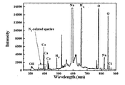
- FIG. 6 is a diagram illustrating concentrations of active species generated in the fluid when no gas is supplied to the gas supply unit 106.
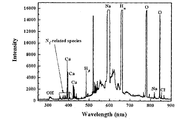
- FIG. 7 illustrates concentrations of active species generated in the fluid when nitrogen (N 2 ) is supplied to the gas supply unit 106.
- FIG. 8 is a view showing the concentration of active species generated in the fluid when the air is supplied to the gas supply 106.
- E. coli Escherichia coli
- FIG. 1 is a block diagram illustrating the underwater capillary plasma apparatus 100 according to an embodiment of the present invention.
- the underwater capillary plasma apparatus 100 includes a power supply 102, a discharge electrode 104 and a gas supply 106.
- the power supply unit 102 receives an external power source (for example, a commercial AC power source) and converts it into a DC or AC power source having a voltage of a predetermined size and outputs the converted power.
- an external power source for example, a commercial AC power source
- an external power source for example, a commercial AC power source
- the power supply unit 102 of the present invention may also use a circuit for outputting an AC power source.
- the power supply unit 102 may include a transformer 108 and a rectifier 110 to amplify the voltage of the input power.
- the power supply unit 102 may be configured in an appropriate form according to the type and voltage of the input power and the type of the output power.
- the discharge electrode 104 receives the power supplied from the power supply 102 to generate a capillary plasma discharge 114 inside the contaminated fluid 112 to purify the fluid 112 such as contaminated water. .
- the plasma generated by the capillary plasma discharge decomposes water molecules inside the fluid 112 to generate active species such as OH ⁇ , O, H, H 2 O 2 , HO 2 , HClO, Cl 2 , HCl, and the like.
- the generated active species removes contaminants (volatile organic compounds, microorganisms, algae, etc.) in the fluid.
- the gas supply unit 106 injects the auxiliary gas into the fluid 112 where the capillary plasma discharge occurs by the discharge electrode 104.
- an auxiliary gas may be ozone (O 3 ), oxygen (O 2 ), nitrogen (N 2 ), argon (Ar), helium (He), air, or mixtures thereof, or It is also possible to inject liquid hydrogen peroxide (H 2 O 2 ) in the gas supply portion 106.
- the auxiliary gas injected as described above is supplied to the plasma generated from the discharge electrode 104, thereby assisting the generation of the plasma and the purification of the fluid 112 through the plasma.
- the concentration of the active species in the fluid 112 and the residence time in the fluid are increased as compared with the case where the auxiliary gas is not injected. 112)
- the purification effect can be maximized.
- plasma can be generated even with a lower power supply than when the gas is not injected, thereby reducing energy consumption for fluid purification.
- FIG 2 is a view showing a first embodiment of the discharge electrode 104 and the gas supply unit 106 of the underwater capillary plasma apparatus 100 according to the present invention.
- the discharge electrode 104 comprises a metal tip 200 and a dielectric tube 202.
- the metal tip 200 is electrically connected to the output terminal of the power supply 102 and may be made of a metal material, for example, one of tungsten, molybdenum, titanium, or stainless steel (SUS).
- the material constituting the metal tip 200 may be determined in consideration of the shape, size, workability or price of the metal material 200, and the like.
- the metal tip 200 may be made of stainless steel having good workability, and the end portion at which plasma is generated may be formed of tungsten or the like having high abrasion resistance.
- the dielectric tube 202 has a cylindrical shape surrounding the metal tip 200, and protrudes by a predetermined length d from the end of the metal tip 200. That is, the end portion of the metal tip 200 is formed to enter the inside of the dielectric tube 202 by d.
- the d may be appropriately determined in consideration of the microbubble formed in the dielectric tube 202 and the discharge effect generated in the microbubble, and may have a value of about 2 mm to 4 mm.
- the dielectric tube 202 may be made of, for example, alumina or quartz.
- the diameter a of the dielectric tube 202 may be formed to about 2 mm to 4 mm.
- the gas supply unit 106 includes a gas supply pipe 204 for supplying auxiliary gas into the fluid.
- the gas supply pipe 304 is formed to penetrate the metal tip 200 in the longitudinal direction, and thus is configured to supply the auxiliary gas directly to the plasma generated at the end of the metal tip 200.
- the diameter b of the gas supply pipe 204 may be formed to about 0.7 mm to 1.2 mm.
- FIG 3 is a view showing a second embodiment of the discharge electrode 104 and the gas supply unit 106 of the underwater capillary plasma apparatus 100 according to the present invention.
- This embodiment also includes a metal tip 300, a dielectric tube 302 and a gas supply pipe 304 as in Example 1, but as shown in the present embodiment compared to Example 1, the gas
- the shape of the supply pipe 304 is different. That is, in this embodiment, the gas supply pipe 304 is formed so that its diameter is narrow at the end of the metal tip 200 in contact with the fluid. That is, in the drawing, c> b (where c is the inner diameter of the gas supply pipe 304, b is the diameter of the gas outlet portion of the gas supply pipe 304).
- c the inner diameter of the gas supply pipe 304
- b is the diameter of the gas outlet portion of the gas supply pipe 304.
- FIG 4 is a view showing a third embodiment of the discharge electrode 104 and the gas supply unit 106 of the underwater capillary plasma apparatus 100 according to the present invention.
- This embodiment also includes a metal tip 400, a dielectric tube 402, and a gas supply tube 404, similar to Examples 1 and 2, but in comparison with Examples 1 and 2 of the dielectric tube 402
- the shape is different. That is, in the present embodiment, the end 406 portion in contact with the fluid of the dielectric tube 402 is configured to be inclined in the direction of the outer circumferential surface from the inner circumferential surface of the cylinder constituting the dielectric tube 402. As such, when the inclined surface is formed at the end of the dielectric tube 402, wear of the dielectric tube 402 by plasma can be reduced.
- the shape of the gas supply pipe 404 is illustrated to be the same as that of the second embodiment, but this is only an example, and a gas supply pipe having the same shape as that of FIG. 2 may be employed.
- FIG 5 is a view showing a fourth embodiment of the discharge electrode 104 and the gas supply unit 106 of the underwater capillary plasma apparatus 100 according to the present invention.
- the gas supply pipe 404 is not formed through the inside of the metal tip 500, but has a cylindrical shape surrounding the dielectric tube 502.
- the auxiliary gas is not directly injected into the plasma formed at the end of the metal tip 500, but is supplied in a form surrounding the outside of the plasma.
- 6 to 10 are views for explaining the effect of the underwater capillary plasma apparatus 100 according to the present invention.
- FIG. 6 illustrates a case in which no gas is supplied to the gas supply unit 106
- FIG. 7 illustrates a case in which air is supplied to the gas supply unit 106 when nitrogen (N 2 ) is supplied to the gas supply unit 106.
- N 2 nitrogen
- the concentration of active species generated in the fluid is shown.
- the concentration of O, OH, etc. increases when nitrogen or air is supplied to the gas supply unit 106.
- FIG 9 is a graph comparing the amount of chlorine in the fluid when various kinds of gases are injected into the gas supply unit 106.
- O _O 3 when injecting the ozone gas generated from oxygen, Air_O 3 shows the case of injecting the ozone gas generated from the air, respectively.
- the amount of Total Cl which acts as a sterilizer, increased when a gas such as oxygen, nitrogen, air, or ozone was injected as compared with the case where no gas was injected (Non-gas).
- E. coli Escherichia coli
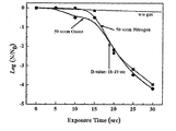
- the number of Escherichia coli in the fluid does not decrease in the case of no gas supply (w / o gas), but the number of E. coli suddenly increases from about 15 seconds when 50 sccm of nitrogen or 50 sccm of ozone is supplied. It can be seen that the decrease.
- the underwater capillary plasma apparatus having a gas channel of the present invention as described above can be used in various applications, such as purification of ballast water, disinfection of water used in medical equipment, tableware, humidifiers, and other wastewater treatment.
Landscapes
- Engineering & Computer Science (AREA)
- Plasma & Fusion (AREA)
- Physics & Mathematics (AREA)
- Chemical & Material Sciences (AREA)
- Hydrology & Water Resources (AREA)
- Life Sciences & Earth Sciences (AREA)
- Spectroscopy & Molecular Physics (AREA)
- Environmental & Geological Engineering (AREA)
- Water Supply & Treatment (AREA)
- Organic Chemistry (AREA)
- Chemical Kinetics & Catalysis (AREA)
- Electrochemistry (AREA)
- General Chemical & Material Sciences (AREA)
- Plasma Technology (AREA)
- Physical Or Chemical Processes And Apparatus (AREA)
Abstract
La présente invention a trait à un dispositif au plasma de tube capillaire sous-marin doté d'un canal de gaz. Selon un mode de réalisation de la présente invention, un dispositif au plasma de tube capillaire sous-marin comprend : un bloc d'alimentation qui fournit de l'énergie ; une électrode de décharge qui reçoit l'énergie fournie par ledit bloc d'alimentation et qui induit une décharge au plasma de tube capillaire à l'intérieur d'un fluide ; et une unité d'alimentation en gaz qui injecte un gaz auxiliaire dans ladite électrode de décharge. Selon les modes de réalisation de la présente invention, dans la mesure où un canal de gaz est prévu dans une électrode de décharge au plasma de tube capillaire sous-marin, diverses espèces réactives chimiques sont créées en fonction du gaz injecté, y compris des espèces plasma qui sont créées à partir de la décomposition de l'eau causée par une décharge au plasma, ce qui permet de la sorte de supprimer de façon efficace les polluants sous-marins. De plus, si le gaz est injecté selon la présente invention, la concentration et la durée de vie, à l'intérieur d'un fluide, des espèces réactives qui sont créées par la décharge au plasma sont augmentées de sorte qu'un effet de purification par plasma peut être maximisé. En outre, si un tel gaz auxiliaire est fourni, le plasma peut être généré y compris par une alimentation en énergie inférieure par rapport à lorsque le gaz n'est pas injecté, ce qui permet de réduire la consommation d'énergie nécessaire à la purification d'un fluide.
Priority Applications (3)
| Application Number | Priority Date | Filing Date | Title |
|---|---|---|---|
| ES12792771T ES2765052T3 (es) | 2011-05-31 | 2012-05-23 | Dispositivo de plasma capilar sumergible |
| CN201280026758.1A CN103635434B (zh) | 2011-05-31 | 2012-05-23 | 具有气体通道的水下毛细管等离子体装置 |
| EP12792771.3A EP2716606B1 (fr) | 2011-05-31 | 2012-05-23 | Dispositif immergé à plasma capillaire |
Applications Claiming Priority (2)
| Application Number | Priority Date | Filing Date | Title |
|---|---|---|---|
| KR10-2011-0052089 | 2011-05-31 | ||
| KR1020110052089A KR101266157B1 (ko) | 2011-05-31 | 2011-05-31 | 가스 채널을 구비한 수중 모세관 플라즈마 장치 |
Publications (2)
| Publication Number | Publication Date |
|---|---|
| WO2012165799A2 true WO2012165799A2 (fr) | 2012-12-06 |
| WO2012165799A3 WO2012165799A3 (fr) | 2013-02-21 |
Family
ID=47260028
Family Applications (1)
| Application Number | Title | Priority Date | Filing Date |
|---|---|---|---|
| PCT/KR2012/004073 Ceased WO2012165799A2 (fr) | 2011-05-31 | 2012-05-23 | Dispositif au plasma de tube capillaire sous-marin doté d'un canal de gaz |
Country Status (5)
| Country | Link |
|---|---|
| EP (1) | EP2716606B1 (fr) |
| KR (1) | KR101266157B1 (fr) |
| CN (1) | CN103635434B (fr) |
| ES (1) | ES2765052T3 (fr) |
| WO (1) | WO2012165799A2 (fr) |
Cited By (5)
| Publication number | Priority date | Publication date | Assignee | Title |
|---|---|---|---|---|
| CN105883966A (zh) * | 2014-12-24 | 2016-08-24 | 苏州超等环保科技有限公司 | 一种水处理高效等离子负载 |
| CN105884063A (zh) * | 2015-06-04 | 2016-08-24 | 庞浩辉 | 一种废水再生纯净水系统装置 |
| CN105948300A (zh) * | 2016-07-26 | 2016-09-21 | 上海能洲环保科技有限公司 | 储能即热式安全热饮机 |
| CN106007046A (zh) * | 2016-05-10 | 2016-10-12 | 上海电力学院 | 一种脱硫废水硬度离子资源化预处理工艺 |
| CN109761304A (zh) * | 2019-03-05 | 2019-05-17 | 成都科衡环保技术有限公司 | 用于水处理的微波等离子体发生模块、反应器及其应用 |
Families Citing this family (15)
| Publication number | Priority date | Publication date | Assignee | Title |
|---|---|---|---|---|
| KR101428525B1 (ko) * | 2012-12-27 | 2014-08-11 | 한국기초과학지원연구원 | 수중 종자 플라즈마 처리 방법 |
| KR101575693B1 (ko) * | 2014-01-29 | 2015-12-21 | 한국기초과학지원연구원 | 플라즈마 수처리 장치 |
| CN105565447B (zh) * | 2015-11-06 | 2018-05-08 | 济宁普悦环保科技有限公司 | 节能灭菌水池 |
| KR101709644B1 (ko) * | 2015-12-21 | 2017-02-23 | 에스케이건설 주식회사 | 과산화수소를 생성하는 수처리 장치 |
| US10822255B2 (en) | 2017-07-14 | 2020-11-03 | Doosan Heavy Industries & Construction Co., Ld | Water treatment apparatus using underwater plasma discharge and water treatment system including same |
| KR101953691B1 (ko) | 2018-05-29 | 2019-03-04 | 이석 | 수중 유전체 장벽 방전 플라즈마 발생 장치 |
| KR101984437B1 (ko) | 2018-12-26 | 2019-05-30 | 김숙 | 플라즈마 수처리장치 |
| KR102219915B1 (ko) * | 2019-04-10 | 2021-02-23 | 부산대학교 산학협력단 | 가스-액체 계면 플라즈마 공정을 이용한 술폰화된 고체산 촉매의 제조방법 |
| KR102106879B1 (ko) * | 2019-06-07 | 2020-05-07 | 한국기초과학지원연구원 | 플라즈마 발생장치 및 이를 구비한 수처리 시스템 |
| CN110418484B (zh) * | 2019-08-30 | 2020-11-06 | 西安交通大学 | 一种空气射流放电产生装置 |
| CN111405739B (zh) * | 2020-03-06 | 2021-05-18 | 大连理工大学 | 一种大气压毛细管内均匀放电微等离子体发生装置 |
| KR102479272B1 (ko) * | 2020-03-26 | 2022-12-20 | 한국핵융합에너지연구원 | 플라즈마 방전수를 이용한 방역 시스템 및 플라즈마 방전수를 액적으로 분무하는 분무노즐 |
| KR102458891B1 (ko) * | 2020-10-19 | 2022-10-24 | 가톨릭대학교 산학협력단 | 내시경 채널 소독 장치 |
| CN114513890A (zh) * | 2022-04-19 | 2022-05-17 | 北京大学第三医院(北京大学第三临床医学院) | 一种高能量利用率的等离子体杀菌装置和应用 |
| KR20250116422A (ko) * | 2024-01-25 | 2025-08-01 | 한국기계연구원 | 플라즈마 수처리 장치, 이를 포함하는 플라즈마를 이용한 폐수 정화 시스템, 및 플라즈마를 이용한 폐수 정화 방법 |
Family Cites Families (8)
| Publication number | Priority date | Publication date | Assignee | Title |
|---|---|---|---|---|
| US5464513A (en) * | 1994-01-11 | 1995-11-07 | Scientific Utilization, Inc. | Method and apparatus for water decontamination using electrical discharge |
| JP2000260396A (ja) * | 1999-03-05 | 2000-09-22 | Quark Systems Co Ltd | エキシマランプ、エキシマ照射装置および有機化合物の分解方法 |
| US20050189278A1 (en) * | 2004-02-03 | 2005-09-01 | Takanori Iijima | Apparatus for decomposing organic matter with radical treatment method using electric discharge |
| EP1951625B1 (fr) * | 2005-10-25 | 2011-04-06 | Aseptix Technologies B.V | Solutions de peroxyde activées et procédé de préparation |
| WO2009036579A1 (fr) * | 2007-09-21 | 2009-03-26 | Hoffmann Neopac Ag | Appareil pour revêtement appliqué sous plasma de la surface interne de contenants d'emballage tubulaires en matière plastique au moyen d'un faisceau-plasma non thermique à pression ambiante réactive |
| KR100967878B1 (ko) * | 2007-11-27 | 2010-07-05 | 주식회사 에스디알앤디 | 수중 플라즈마 발생장치 및 방법 |
| KR20090110060A (ko) * | 2008-04-17 | 2009-10-21 | 주식회사 에스디알앤디 | 수중 플라즈마 발생장치 및 방법 |
| KR100924649B1 (ko) * | 2009-05-22 | 2009-11-02 | 정장근 | 고밀도 수중 플라즈마 토치의 발생장치 및 방법 |
-
2011
- 2011-05-31 KR KR1020110052089A patent/KR101266157B1/ko active Active
-
2012
- 2012-05-23 ES ES12792771T patent/ES2765052T3/es active Active
- 2012-05-23 CN CN201280026758.1A patent/CN103635434B/zh active Active
- 2012-05-23 EP EP12792771.3A patent/EP2716606B1/fr active Active
- 2012-05-23 WO PCT/KR2012/004073 patent/WO2012165799A2/fr not_active Ceased
Non-Patent Citations (2)
| Title |
|---|
| None |
| See also references of EP2716606A4 |
Cited By (6)
| Publication number | Priority date | Publication date | Assignee | Title |
|---|---|---|---|---|
| CN105883966A (zh) * | 2014-12-24 | 2016-08-24 | 苏州超等环保科技有限公司 | 一种水处理高效等离子负载 |
| CN105884063A (zh) * | 2015-06-04 | 2016-08-24 | 庞浩辉 | 一种废水再生纯净水系统装置 |
| CN106007046A (zh) * | 2016-05-10 | 2016-10-12 | 上海电力学院 | 一种脱硫废水硬度离子资源化预处理工艺 |
| CN105948300A (zh) * | 2016-07-26 | 2016-09-21 | 上海能洲环保科技有限公司 | 储能即热式安全热饮机 |
| CN105948300B (zh) * | 2016-07-26 | 2019-01-11 | 上海能洲环保科技有限公司 | 储能即热式安全热饮机 |
| CN109761304A (zh) * | 2019-03-05 | 2019-05-17 | 成都科衡环保技术有限公司 | 用于水处理的微波等离子体发生模块、反应器及其应用 |
Also Published As
| Publication number | Publication date |
|---|---|
| WO2012165799A3 (fr) | 2013-02-21 |
| CN103635434B (zh) | 2016-01-20 |
| EP2716606A2 (fr) | 2014-04-09 |
| ES2765052T3 (es) | 2020-06-05 |
| EP2716606A4 (fr) | 2014-11-05 |
| EP2716606B1 (fr) | 2019-12-04 |
| KR101266157B1 (ko) | 2013-05-21 |
| KR20120133454A (ko) | 2012-12-11 |
| CN103635434A (zh) | 2014-03-12 |
Similar Documents
| Publication | Publication Date | Title |
|---|---|---|
| WO2012165799A2 (fr) | Dispositif au plasma de tube capillaire sous-marin doté d'un canal de gaz | |
| KR101256577B1 (ko) | 수중 방전 전극 및 이를 포함하는 수중 모세관 플라즈마 방전 장치 | |
| US9346691B2 (en) | Tubular high-density plasma reactor, with outer treatment chamber and collinear rotatable inner cylinder | |
| WO2011149188A2 (fr) | Appareil et procédé pour décontaminer et stériliser un agent chimique et biologique | |
| KR100932377B1 (ko) | 고밀도 수중 플라즈마 토치를 이용한 수질정화방법 | |
| WO2013081300A1 (fr) | Appareil de traitement d'eau à plasma | |
| KR101918147B1 (ko) | 플라즈마 수처리 장치 | |
| JP2000093967A (ja) | 液体処理方法及び液体処理装置 | |
| WO2016178501A1 (fr) | Dispositif de production de plasma subaquatique à basse température | |
| JP2010137212A (ja) | プラズマ発生装置 | |
| JP7675300B2 (ja) | コロナ放電区域内で成分どうしをオゾンなしで分離するための方法及び装置 | |
| JP2001058803A (ja) | 高電圧放電を利用したイオン化ガスの発生装置 | |
| KR100316802B1 (ko) | 고전압 방전을 이용한 이온화가스 발생장치 | |
| KR19980042980A (ko) | 오수 정화 장치 | |
| KR100902138B1 (ko) | 오존을 이용한 폐수 정화 장치 | |
| CN205773502U (zh) | 一种废水处理装置 | |
| KR100304461B1 (ko) | 오수정화장치 | |
| WO2015137573A1 (fr) | Système d'épuration des eaux usées utilisant une décharge à haute tension et des microbulles | |
| KR101808768B1 (ko) | 플라즈마 전극 및 이를 구비한 수중 플라즈마 장치 | |
| KR20010048824A (ko) | 전기 분해 반응과 광산화 반응을 동시에 일으키는 폐수처리 시스템 | |
| KR19990007560A (ko) | 고전압 방전을 이용한 폐수처리 장치 | |
| KR20220012035A (ko) | 폐수 처리를 위한 오존 발생 장치와 결합된 수중 아크 플라즈마 시스템 | |
| US20250368549A1 (en) | Sterilization purification system of contaminated water using a plasma generator | |
| KR100429611B1 (ko) | 산소원자를 이용하여 오폐수를 처리하는 방법 및 시스템 | |
| KR101575693B1 (ko) | 플라즈마 수처리 장치 |
Legal Events
| Date | Code | Title | Description |
|---|---|---|---|
| 121 | Ep: the epo has been informed by wipo that ep was designated in this application |
Ref document number: 12792771 Country of ref document: EP Kind code of ref document: A2 |
|
| NENP | Non-entry into the national phase |
Ref country code: DE |