WO2012168997A1 - Dispositif limiteur de couple pour véhicule - Google Patents
Dispositif limiteur de couple pour véhicule Download PDFInfo
- Publication number
- WO2012168997A1 WO2012168997A1 PCT/JP2011/062962 JP2011062962W WO2012168997A1 WO 2012168997 A1 WO2012168997 A1 WO 2012168997A1 JP 2011062962 W JP2011062962 W JP 2011062962W WO 2012168997 A1 WO2012168997 A1 WO 2012168997A1
- Authority
- WO
- WIPO (PCT)
- Prior art keywords
- friction
- friction material
- plate
- cover plate
- stopper
- Prior art date
- Legal status (The legal status is an assumption and is not a legal conclusion. Google has not performed a legal analysis and makes no representation as to the accuracy of the status listed.)
- Ceased
Links
Images






Classifications
-
- F—MECHANICAL ENGINEERING; LIGHTING; HEATING; WEAPONS; BLASTING
- F16—ENGINEERING ELEMENTS AND UNITS; GENERAL MEASURES FOR PRODUCING AND MAINTAINING EFFECTIVE FUNCTIONING OF MACHINES OR INSTALLATIONS; THERMAL INSULATION IN GENERAL
- F16D—COUPLINGS FOR TRANSMITTING ROTATION; CLUTCHES; BRAKES
- F16D7/00—Slip couplings, e.g. slipping on overload, for absorbing shock
- F16D7/02—Slip couplings, e.g. slipping on overload, for absorbing shock of the friction type
- F16D7/024—Slip couplings, e.g. slipping on overload, for absorbing shock of the friction type with axially applied torque limiting friction surfaces
- F16D7/025—Slip couplings, e.g. slipping on overload, for absorbing shock of the friction type with axially applied torque limiting friction surfaces with flat clutching surfaces, e.g. discs
-
- F—MECHANICAL ENGINEERING; LIGHTING; HEATING; WEAPONS; BLASTING
- F16—ENGINEERING ELEMENTS AND UNITS; GENERAL MEASURES FOR PRODUCING AND MAINTAINING EFFECTIVE FUNCTIONING OF MACHINES OR INSTALLATIONS; THERMAL INSULATION IN GENERAL
- F16F—SPRINGS; SHOCK-ABSORBERS; MEANS FOR DAMPING VIBRATION
- F16F15/00—Suppression of vibrations in systems; Means or arrangements for avoiding or reducing out-of-balance forces, e.g. due to motion
- F16F15/10—Suppression of vibrations in rotating systems by making use of members moving with the system
- F16F15/12—Suppression of vibrations in rotating systems by making use of members moving with the system using elastic members or friction-damping members, e.g. between a rotating shaft and a gyratory mass mounted thereon
- F16F15/129—Suppression of vibrations in rotating systems by making use of members moving with the system using elastic members or friction-damping members, e.g. between a rotating shaft and a gyratory mass mounted thereon characterised by friction-damping means
- F16F15/1297—Overload protection, i.e. means for limiting torque
-
- B—PERFORMING OPERATIONS; TRANSPORTING
- B60—VEHICLES IN GENERAL
- B60K—ARRANGEMENT OR MOUNTING OF PROPULSION UNITS OR OF TRANSMISSIONS IN VEHICLES; ARRANGEMENT OR MOUNTING OF PLURAL DIVERSE PRIME-MOVERS IN VEHICLES; AUXILIARY DRIVES FOR VEHICLES; INSTRUMENTATION OR DASHBOARDS FOR VEHICLES; ARRANGEMENTS IN CONNECTION WITH COOLING, AIR INTAKE, GAS EXHAUST OR FUEL SUPPLY OF PROPULSION UNITS IN VEHICLES
- B60K6/00—Arrangement or mounting of plural diverse prime-movers for mutual or common propulsion, e.g. hybrid propulsion systems comprising electric motors and internal combustion engines
- B60K6/20—Arrangement or mounting of plural diverse prime-movers for mutual or common propulsion, e.g. hybrid propulsion systems comprising electric motors and internal combustion engines the prime-movers consisting of electric motors and internal combustion engines, e.g. HEVs
- B60K6/22—Arrangement or mounting of plural diverse prime-movers for mutual or common propulsion, e.g. hybrid propulsion systems comprising electric motors and internal combustion engines the prime-movers consisting of electric motors and internal combustion engines, e.g. HEVs characterised by apparatus, components or means specially adapted for HEVs
- B60K6/36—Arrangement or mounting of plural diverse prime-movers for mutual or common propulsion, e.g. hybrid propulsion systems comprising electric motors and internal combustion engines the prime-movers consisting of electric motors and internal combustion engines, e.g. HEVs characterised by apparatus, components or means specially adapted for HEVs characterised by the transmission gearings
- B60K6/365—Arrangement or mounting of plural diverse prime-movers for mutual or common propulsion, e.g. hybrid propulsion systems comprising electric motors and internal combustion engines the prime-movers consisting of electric motors and internal combustion engines, e.g. HEVs characterised by apparatus, components or means specially adapted for HEVs characterised by the transmission gearings with the gears having orbital motion
-
- B—PERFORMING OPERATIONS; TRANSPORTING
- B60—VEHICLES IN GENERAL
- B60K—ARRANGEMENT OR MOUNTING OF PROPULSION UNITS OR OF TRANSMISSIONS IN VEHICLES; ARRANGEMENT OR MOUNTING OF PLURAL DIVERSE PRIME-MOVERS IN VEHICLES; AUXILIARY DRIVES FOR VEHICLES; INSTRUMENTATION OR DASHBOARDS FOR VEHICLES; ARRANGEMENTS IN CONNECTION WITH COOLING, AIR INTAKE, GAS EXHAUST OR FUEL SUPPLY OF PROPULSION UNITS IN VEHICLES
- B60K6/00—Arrangement or mounting of plural diverse prime-movers for mutual or common propulsion, e.g. hybrid propulsion systems comprising electric motors and internal combustion engines
- B60K6/20—Arrangement or mounting of plural diverse prime-movers for mutual or common propulsion, e.g. hybrid propulsion systems comprising electric motors and internal combustion engines the prime-movers consisting of electric motors and internal combustion engines, e.g. HEVs
- B60K6/42—Arrangement or mounting of plural diverse prime-movers for mutual or common propulsion, e.g. hybrid propulsion systems comprising electric motors and internal combustion engines the prime-movers consisting of electric motors and internal combustion engines, e.g. HEVs characterised by the architecture of the hybrid electric vehicle
- B60K6/44—Series-parallel type
- B60K6/445—Differential gearing distribution type
-
- Y—GENERAL TAGGING OF NEW TECHNOLOGICAL DEVELOPMENTS; GENERAL TAGGING OF CROSS-SECTIONAL TECHNOLOGIES SPANNING OVER SEVERAL SECTIONS OF THE IPC; TECHNICAL SUBJECTS COVERED BY FORMER USPC CROSS-REFERENCE ART COLLECTIONS [XRACs] AND DIGESTS
- Y02—TECHNOLOGIES OR APPLICATIONS FOR MITIGATION OR ADAPTATION AGAINST CLIMATE CHANGE
- Y02T—CLIMATE CHANGE MITIGATION TECHNOLOGIES RELATED TO TRANSPORTATION
- Y02T10/00—Road transport of goods or passengers
- Y02T10/60—Other road transportation technologies with climate change mitigation effect
- Y02T10/62—Hybrid vehicles
Definitions
- the present invention relates to a vehicle torque limiter device, and more particularly to a structure of a torque limiter device capable of obtaining a hysteresis torque with a simple structure.
- a vehicle torque limiter device having a pressing member for generating a pressing force with a plate is known.
- the torque fluctuation absorber of Patent Document 1 is an example.
- the torque fluctuation absorber 1 described in Patent Document 1 elastically supports a side plate 22 that can rotate about an axis, a hub 21 that can rotate relative to the side plate 22 and a coaxial axis, and the side plate 22 and the hub 21.
- the damper mechanism 20 includes a damper member 24 that is connected to the damper mechanism 20, and a limiter unit 30 (torque limiter device) that is disposed on the outer peripheral side of the damper mechanism 20.
- a hysteresis mechanism thrust member, disk spring 23c
- a limiter portion 30 is provided on the outer peripheral side thereof. Is provided.
- a hysteresis mechanism (first hysteresis mechanism) that generates a two-stage hysteresis torque between the hub 21 and the first side plate 22A and the second side plate 22B.
- a second hysteresis mechanism (second hysteresis mechanism) that generates a two-stage hysteresis torque between the hub 21 and the first side plate 22A and the second side plate 22B.
- the present invention has been made against the background of the above circumstances, and an object of the present invention is to provide a vehicle torque limiter device capable of obtaining a hysteresis torque with a simple structure.
- the gist of the invention according to claim 1 is that: (a) a cover plate rotatable around an axis, a lining plate rotatable relative to the cover plate and a coaxial axis; In the vehicle torque limiter device having a friction material interposed between the cover plate and the lining plate, and a pressing member for generating a pressing force between the cover plate and the lining plate, (b) The cover plate and the friction material are configured to be slidable from each other, (c) the lining plate and the friction material are configured to be slidable from each other, and (d) the cover plate and the friction material The frictional force generated on the frictional surface between the friction material is smaller than the frictional force generated on the frictional surface between the lining plate and the friction material, and (e) the cover Between rate and the friction member, wherein the stopper defining the slippage between the cover plate and its friction material is provided.
- the friction force generated on the friction surface between the cover plate and the friction material is configured to be smaller than the friction force generated on the friction surface between the lining plate and the friction material. Therefore, when torque is input to the torque limiter device, the slip is first generated between the cover plate and the friction material, and the lining plate and the friction material rotate integrally. At this time, a hysteresis torque based on the frictional force between the cover plate and the friction material is generated. That is, the cover plate and the friction material constituting the torque limiter device function as a hysteresis mechanism. When the slip amount between the cover plate and the friction material reaches a specified value, the stopper is operated, and the slip between the cover plate and the friction material is prevented.
- the torque limiter device functions as a normal torque limiter based on the frictional force generated on the friction surface between the lining plate and the friction material.
- the torque limiter device that can also generate the hysteresis torque with a simple structure can be realized by using the torque limiter device also as the hysteresis mechanism.
- the torque limiter device is arranged on the outer peripheral side, the operating radius of the torque limiter device is increased, so that even a large hysteresis torque can be realized.
- the cover plate includes a pair of a first cover plate and a second cover plate, and (b) a first friction between the first cover plate and the lining plate.
- a material is inserted as the friction material
- a second friction material is further inserted as the friction material between the second cover plate and the lining plate
- the first cover A first stopper is provided as the stopper between the plate and the first friction material; and (e) a second stopper is further provided between the second cover plate and the second friction material.
- the slip amount defined by the first stopper is smaller than the slip amount defined by the second stopper; and (g) the first cover plate and the first cover.
- Frictional force generated on the friction surface with the friction material The friction force generated on the friction surface between the second cover plate and the second friction material is greater than the friction force generated on the friction surface between the lining plate and the first friction material. (H) The friction force generated on the friction surface between the lining plate and the first friction material is smaller than the friction force generated on the friction surface between the lining plate and the second friction material. Is also small.
- a cover plate that can rotate about an axis, a lining plate that can rotate relative to the cover plate and a coaxial axis, and the cover plate and the lining plate are interposed.
- a torque limiter device for a vehicle having a friction material, and a pressing member for generating a pressing force between the cover plate and the lining plate, wherein (b) the cover plate and the friction material are mutually (C) the lining plate and the friction material are configured to be slidable with each other, and (d) when torque is input to the torque limiter portion, the cover plate and the friction material
- a friction surface between the cover plate and the friction material is configured to slide before a friction surface between the lining plate and the friction material; It is characterized in that a stopper for defining the slip amount between the cover plate and its friction material is provided.
- the torque limiter device when torque is input to the torque limiter device, first, slip occurs between the cover plate and the friction material, and the lining plate and the friction material rotate integrally. At this time, a hysteresis torque based on the frictional force between the cover plate and the friction material is generated. That is, the cover plate and the friction material constituting the torque limiter device function as a hysteresis mechanism. When the slip amount between the cover plate and the friction material reaches a specified value, the stopper is operated, and the slip between the cover plate and the friction material is prevented. Thus, the torque limiter device functions as a normal torque limiter based on the frictional force generated on the friction surface between the lining plate and the friction material.
- the torque limiter device that can also generate the hysteresis torque with a simple structure can be realized by using the torque limiter device also as the hysteresis mechanism. Moreover, since the operating radius of the torque limiter device is increased by arranging the torque limiter device on the outer peripheral side of the conventional hysteresis mechanism, a large hysteresis torque can be obtained.
- the cover plate includes a pair of a first cover plate and a second cover plate, and (b) a first friction between the first cover plate and the lining plate.
- a material is inserted as the friction material
- a second friction material is further inserted as the friction material between the second cover plate and the lining plate
- the first cover A first stopper is provided as the stopper between the plate and the first friction material; and (e) a second stopper is provided between the second cover plate and the second friction material.
- the slip amount defined by the first stopper is smaller than the slip amount defined by the second stopper, and (g) when torque is input to the torque limiter unit, The first cover plate and the first cover plate; The friction surface between the friction material and the friction surface between the second cover plate and the second friction material first slips, and then between the lining plate and the first friction material. The friction surface slides, and finally, the friction surface between the lining plate and the second friction material slides.
- torque limiter device first, the friction surface between the first cover plate and the first friction material, and the second cover plate and the second friction. Slip occurs on the friction surface with the material, and at this time, a first hysteresis torque is generated.
- the torque limiter portion functions as a normal torque limiter based on the frictional force generated between the lining plate and the second friction material. In this way, a torque limiter device that can obtain a two-stage hysteresis torque can be realized.
- the torque limiter device includes (a) a plurality of the first friction materials arranged separately in a circumferential direction, (b) a plurality of the first friction materials, and the first friction material.
- a plurality of the first stoppers defining a slip amount with respect to the cover plate, (c) a plurality of the second friction members arranged separately in the circumferential direction, and (d) a plurality of the first friction materials.
- a plurality of second stoppers that define the amount of sliding between the second friction material and the second cover plate, and (e) the plurality of first friction materials and the plurality of first friction materials.
- the friction material 2 has a friction coefficient different from that of the lining plate, and the friction material having a friction surface having a large friction coefficient with the lining plate has a higher friction coefficient than that of the first stopper or the second stopper.
- the specified slip amount is set large. In this way, a torque limiter that can obtain a multistage hysteresis torque by differentiating the friction coefficients of the friction surfaces of the plurality of first friction materials and the plurality of second friction materials and the lining plate. An apparatus can be realized.
- FIG. 3 is an enlarged cross-sectional view in which the torque limiter mechanism of FIG. 2 is partially enlarged. It is the arrow line view which looked at the pressure plate and the 1st friction material of FIG. 3 from the arrow A side. It is a figure which shows the relationship between the torque transmitted to the damper apparatus of FIG. 2, and a twist angle. It is sectional drawing for demonstrating the structure of the torque limiter mechanism of the damper apparatus which is the other Example of this invention. It is a figure which shows the relationship between the torque transmitted to the damper apparatus of FIG. 6, and a twist angle.
- FIG. 9 is a view of the pressure limiter mechanism of FIG. 8 as viewed from the direction of arrow A when the pressure plate and the first friction material are viewed from the arrow A side of FIG. 8.
- FIG. 9 is a B arrow view of the support plate and the second friction material as viewed from the arrow B side of FIG. 8 in the torque limiter mechanism of FIG.
- It is a figure which shows the relationship between the torque transmitted to the damper apparatus of FIG. 8, and a twist angle.
- It is a figure which shows the further another aspect of a stopper.
- It is a figure which shows the relationship between the torque at the time of using the stopper of FIG. 14, and a twist angle.
- FIG. 1 is a schematic configuration diagram illustrating a hybrid vehicle drive device 10 to which the present invention is applied.
- the vehicle drive device 10 in the vehicle, torque of the first drive source 12 that is a main drive source is transmitted to a wheel side output shaft 14 that functions as an output member. Torque is transmitted to the pair of left and right drive wheels 18 via the dynamic gear device 16.
- the vehicle drive device 10 is provided with a second electric motor MG2 capable of selectively executing power running control for outputting driving force for traveling and regenerative control for recovering energy as a second drive source.
- the second electric motor MG2 is connected to the wheel side output shaft via the automatic transmission 22.
- the automatic transmission 22 interposed in the power transmission path between the second electric motor MG2 and the drive wheels 18 is configured to be able to establish a plurality of stages with a gear ratio ⁇ s larger than “1”. Since the torque can be increased and transmitted to the wheel-side output shaft during powering to output torque from the second electric motor MG2, the second electric motor MG2 is configured to have a lower capacity or a smaller size. Thereby, for example, when the rotational speed Nout of the wheel side output shaft increases with the high vehicle speed, the second gear ratio ⁇ s is reduced to maintain the second motor MG2 in a good state.
- the gear ratio ⁇ s is increased to increase the second motor rotational speed Nmg2. Increase.
- the first drive source 12 includes an engine 24 as a main power source, a first electric motor MG1, and a planetary gear as a power distribution mechanism for synthesizing or distributing torque between the engine 24 and the first electric motor MG1.
- the apparatus 26 is mainly configured.
- the engine 24 is a known internal combustion engine that outputs power by burning fuel such as a gasoline engine or a diesel engine.
- the engine 24 is operated by an electronic control device (E-ECU) for engine control (not shown) mainly composed of a microcomputer.
- the operation state such as the throttle valve opening, the intake air amount, the fuel supply amount, and the ignition timing is electrically controlled.
- the electronic control device is supplied with detection signals from an accelerator operation amount sensor AS for detecting the operation amount of the accelerator pedal, a brake sensor BS for detecting whether or not the brake pedal is operated, and the like.
- the first motor MG1 is, for example, a synchronous motor, and is configured to selectively generate a function as a motor that generates a drive torque and a function as a generator, and a battery, a capacitor, and the like are connected via an inverter 30.
- the power storage device 32 is connected.
- the inverter 30 is controlled by an electronic control unit (MG-ECU) (not shown) for controlling the motor generator, which is mainly composed of a microcomputer, so that the output torque or regenerative torque of the first electric motor MG1 is adjusted or set. It is like that.
- MG-ECU electronice control unit
- the planetary gear device 26 includes three types of a sun gear S0, a ring gear R0 arranged concentrically with the sun gear S0, and a carrier CA0 that supports the sun gear S0 and the pinion gear P0 meshing with the ring gear R0 so as to rotate and revolve freely. It is a single pinion type planetary gear mechanism that is provided as a rotating element and generates a known differential action.
- the planetary gear device 26 is provided concentrically with the engine 24 and the automatic transmission 22. Since the planetary gear device 26 and the automatic transmission 22 are configured symmetrically with respect to the center line, the lower half of them is omitted in FIG.
- crankshaft 36 of the engine 24 is connected to the carrier CA0 of the planetary gear unit 26 via the damper device 38 and the power transmission shaft 39.
- the first electric motor MG1 is connected to the sun gear S0, and the wheel side output shaft is connected to the ring gear R0.
- the carrier CA0 functions as an input element
- the sun gear S0 functions as a reaction force element
- the ring gear R0 functions as an output element.
- the reaction torque generated by the first electric motor MG1 is input to the sun gear S0 with respect to the output torque of the engine 24 input to the carrier CA0, the ring gear R0 serving as an output element Since direct torque appears, the first electric motor MG1 functions as a generator. Further, when the rotational speed of the ring gear R0, that is, the rotational speed (output shaft rotational speed) Nout of the wheel side output shaft 14 is constant, the rotational speed Nmg1 of the first electric motor MG1 is changed up and down to thereby increase the rotational speed of the engine 24. (Engine speed) Ne can be changed continuously (steplessly).
- the automatic transmission 22 of the present embodiment is configured by a set of Ravigneaux planetary gear mechanisms. That is, the automatic transmission 22 is provided with a first sun gear S1 and a second sun gear S2. The large diameter portion of the stepped pinion P1 meshes with the first sun gear S1, and the small diameter portion of the stepped pinion P1. Meshes with the pinion P2, and the pinion P2 meshes with the ring gear R1 (R2) disposed concentrically with the sun gears S1 and S2. Each of the pinions P1 and P2 is held by a common carrier CA1 (CA2) so as to rotate and revolve. Further, the second sun gear S2 meshes with the pinion P2.
- CA1 common carrier
- the second electric motor MG2 is controlled as an electric motor or a generator by being controlled by the electronic control unit (MG-ECU) for controlling the motor generator via the inverter 40, and the assist output torque or the regenerative torque is generated. Adjusted or set.
- the second sun gear S2 is connected to the second electric motor MG2, and the carrier CA1 is connected to the wheel side output shaft.
- the first sun gear S1 and the ring gear R1 constitute a mechanism corresponding to a tuple pinion type planetary gear device together with the pinions P1 and P2, and the second sun gear S2 and the ring gear R1 together with the pinion P2 constitute a single pinion type planetary gear device.
- the mechanism equivalent to is comprised.
- the automatic transmission 22 includes a first brake B1 provided between the first sun gear S1 and the housing 42, which is a non-rotating member, and a ring gear R1 in order to selectively fix the first sun gear S1.
- a second brake B2 provided between the ring gear R1 and the housing 42 is provided for selective fixing.
- These brakes B1 and B2 are so-called friction engagement devices that generate a braking force by a frictional force, and a multi-plate type engagement device or a band type engagement device can be adopted.
- These brakes B1 and B2 are configured such that their torque capacities change continuously according to the engagement pressure generated by the brake B1 hydraulic actuator such as a hydraulic cylinder and the brake B2 hydraulic actuator, respectively. Yes.
- the automatic transmission 22 when the second sun gear S2 functions as an input element, the carrier CA1 functions as an output element, and the first brake B1 is engaged, the shift is greater than “1”.
- the high speed stage H with the ratio ⁇ sh is established and the second brake B2 is engaged instead of the first brake B1
- the low speed stage L with the speed ratio ⁇ sl larger than the speed ratio ⁇ sh of the high speed stage H is established. It is configured. That is, the automatic transmission 22 is a two-stage transmission, and the shift between these shift stages H and L is executed based on the running state such as the vehicle speed V and the required driving force (or accelerator operation amount). More specifically, the shift speed region is determined in advance as a map (shift diagram), and control is performed so as to set one of the shift speeds according to the detected driving state.
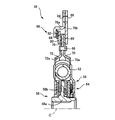
- FIG. 2 is a cross-sectional view for explaining the configuration of the damper device 38 shown in FIG. 1 in detail. 2, the lower half from the axis C is omitted.
- the damper device 38 is provided so that power can be transmitted between the engine 24 and the planetary gear device 26 around the axis C. Further, the power transmission shaft 39 shown in FIG. 1 is spline-fitted to the inner peripheral portion of the damper device 38.
- the damper device 38 is connected to a pair of left and right disk plates 56 rotatable around an axis C and a power transmission shaft 39 so as not to rotate relative to each other by spline fitting, and is provided so as to be rotatable relative to the disk plate 56 around a coaxial axis.
- the hub member 58 is inserted between the disc plate 56 and the hub member 58, and the disc plate 56 and the hub member 58 are operatively deformed elastically according to the relative amount of rotation between the members (
- a coil spring 62 (torsion spring) made of spring steel that is elastically coupled, a hysteresis mechanism 64 that generates a frictional force between the disk plate 56 and the hub member 58, and an outer peripheral side of the disk plate 56.
- the torque limiter mechanism 68 is included.
- the torque limiter mechanism 68 corresponds to the vehicle torque limiter device of the present invention.
- the disc plate 56 is composed of a pair of left and right disc-shaped first plate 70 and second plate 72, and is fixed in a relatively non-rotatable manner by a rivet 66 with the coil spring 62 sandwiched between the plates 70 and 72 in the axial direction.
- the rivet 66 also functions as a fastening member for a lining plate 76 of a torque limiter mechanism 68 described later.
- first plate 70 a plurality of first opening holes 70a for accommodating the coil springs 62 are formed in the circumferential direction.
- the second plate 72 is also formed with a plurality of second opening holes 72a in the circumferential direction at positions corresponding to the first opening holes 70a for accommodating the coil springs 62.
- a plurality of coil springs 62 are accommodated in a space formed by the first opening hole 70a and the second opening hole 72a. Thus, when the disk plate 56 rotates around the axis C, the coil spring 62 is similarly revolved around the axis C.
- the hub member 58 includes a cylindrical portion 58a having an inner peripheral tooth on which the power transmission shaft 39 is spline-fitted on the inner peripheral portion, and a disk-shaped flange portion 58b extending radially outward from the outer peripheral surface of the cylindrical portion 58a. And is formed from. And the coil spring 62 is accommodated in the space formed between each flange part 58b in a rotation direction. Accordingly, when the hub member 58 rotates around the axis C, one end of the coil spring 62 comes into contact with the hub member 58, so that the coil spring 62 is similarly revolved around the axis C.
- the coil spring 62 operatively connects the disk plate 56 and the hub member 58 while elastically deforming according to the relative rotation amount between these members. For example, when the disk plate 56 rotates, one end of the coil spring 62 is pressed, and the other end of the coil spring 62 presses the flange portion 58b of the hub member 58, whereby the hub member 58 is rotated. At this time, the coil spring 62 transmits rotation while being elastically deformed, so that a shock due to torque fluctuation is absorbed by the elastic deformation of the coil spring 62.
- the hysteresis mechanism 64 is provided on the inner peripheral side of the coil spring 62 and is provided between the disk plate 56 and the flange portion 58b of the hub member 58 in the axial direction.
- the hysteresis mechanism 64 is composed of a plurality of friction materials, disk springs, and the like, and generates a frictional force between the disk plate 56 and the hub member 58. An optimum historque is set by adjusting the frictional force.
- the hysteresis mechanism 64 of this embodiment includes a friction engagement element made of a friction material having a low friction coefficient and a friction engagement element made of a friction material having a high friction coefficient, and generates a two-stage hysteresis torque.
- the torque limiter mechanism 68 (the torque limiter device of the present invention) is provided on the further outer peripheral side of the disk plate 56 and has a function of preventing torque transmission exceeding a preset limit torque Tlim.
- the torque limiter mechanism 68 is fastened by a rivet 66 together with the disk plate 56, so that the disk plate 56 and a disk-shaped lining plate 76 that rotates around the axis C integrally and a disk-shaped disk positioned on the outer peripheral side.
- a support plate 78 composed of a first support plate 78a and a disk-shaped second support plate 78b; a disk-shaped pressure plate 80 disposed adjacent to the lining plate 76 so as to be received in the support plate 78;
- a cone-shaped disc spring 82 is inserted in a gap between the pressure plate 80 and the first support plate 78a in the axial direction in a preloaded state, and is inserted between the pressure plate 80 and the lining plate 76.
- the first friction material 88 forriction material
- the second support plate 78b Parts and the second friction member 89 is interposed between the lining plate 76 is constituted comprise.
- the pressure plate 80 corresponds to the cover plate of the present invention.
- FIG. 3 is an enlarged cross-sectional view in which the torque limiter mechanism 68 of FIG. 2 is partially enlarged.
- the support plate 78 includes a pair of left and right disk-shaped first support plates 78a and a disk-shaped second support plate 78b, and the flywheel 50 and the support plates 78a and 78b of FIG.
- Bolt holes 84 and 86 for fastening bolts (not shown) to be fixed are respectively formed.
- the first support plate 78a has a space between the first support plate 78a and the second support plate 78b by bending the inner periphery of the first support plate 78a in the axial direction.
- a disc spring 82, a pressure plate 80, a first friction material 88, a lining plate 76, and a second friction material 89 are sequentially accommodated in the axial direction from the first support plate 78a to the second support plate 78b. ing.
- the lining plate 76 is an annular plate-like member fixed together with the first plate 70 and the second plate 72 by a rivet 66.
- the pressure plate 80 is formed in an annular plate shape.
- the pressure plate 80 and the lining plate 76 are configured to be relatively rotatable around the coaxial center C.
- a first friction material 88 is interposed between the pressure plate 80 and the lining plate 76.
- the first friction material 88 is formed in an annular plate shape, for example. Alternatively, it may be formed in an arc shape and arranged side by side at equal angular intervals in the circumferential direction.
- the friction surface adjacent to the pressure plate 80 is configured to be slidable with the pressure plate 80. Further, the friction surface adjacent to the lining plate 76 of the first friction material 88 is configured to be slidable with the lining plate 76. That is, the first friction material 88 is not fixed to any of the adjacent pressure plate 80 and lining plate 76.
- the friction coefficient ⁇ 1 of the friction surface (sliding surface) between the pressure plate 80 and the first friction material 88 is the friction coefficient of the friction surface (sliding surface) between the lining plate 76 and the first friction material 88.
- the coefficient is smaller than ⁇ 2. That is, the frictional force F1 generated on the friction surface between the pressure plate 80 and the first friction material 88 is smaller than the frictional force F2 generated on the friction surface between the lining plate 76 and the first friction material 88.
- a stopper 90 is provided between the pressure plate 80 and the first friction material 88 to define an upper limit value of the slip amount (relative rotation amount) between the pressure plate 80 and the first friction material 88.
- the stopper 90 includes a cylindrical protrusion 92 that protrudes in the axial direction from the friction surface of the pressure plate 80 with the first friction material 88, and a circular stopper hole 94 formed in the first friction material 88.
- the protrusion 92 is accommodated in the stopper hole 94 and has a play (gap) in the circumferential direction (rotation direction) for defining a predetermined slip amount (relative rotation) between the pressure plate 80 and the first friction material 88. ) Is formed.
- FIG. 4 is an arrow view of the pressure plate 80 and the first friction material 88 as viewed from the arrow A side in FIG.
- the stopper hole 94 is formed in a perfect circular hole larger than the diameter of the protrusion 92.
- a backlash is formed between the protrusion 92 and the stopper hole 94, and slippage in the rotational direction is allowed between the pressure plate 80 and the first friction material 88 by the backlash. Therefore, when the sliding amount between the pressure plate 80 and the first friction material 88 reaches a specified value, the protrusion 92 and the wall surface of the stopper hole 94 come into contact with each other, and the pressure plate 80 and the first friction material 88 are not relatively rotatable. .
- a second friction material 89 is interposed between the inner peripheral portion of the second support plate 78b and the lining plate 76. Similar to the first friction material 88, the second friction material is formed in, for example, an annular plate shape. Alternatively, it may be formed in an arc shape and arranged side by side at equal angular intervals in the circumferential direction.
- the second friction material 89 is configured such that the friction surface on the side adjacent to the second support plate 78b is slidable on the second support plate 78b, and the friction surface adjacent to the lining plate 76 also slides on the lining plate 76. It is configured to be movable. That is, the second friction material 89 is not fixed to any of the adjacent second support plate 78 b and lining plate 76.
- the friction coefficient ⁇ of the friction surface (sliding surface) between the second support plate 78b and the second friction material 89 and the friction surface (sliding surface) between the lining plate 76 and the second friction material 89 is as follows. In both cases, the friction coefficient ⁇ 2 is set.
- a disc spring 82 is inserted between the first support plate 78a and the pressure plate 80 in a preloaded state.
- the disc spring 82 is formed in a cone shape, and its inner peripheral end abuts on the pressure plate 80 and its outer peripheral end abuts on the first support plate 78a to generate the preload (the disc spring load W). The amount of deflection is changed and inserted. Accordingly, the disc spring 82 presses the pressure plate 80 toward the lining plate 76 in the axial direction with the disc spring load W.
- a frictional force F is generated between the two friction materials 89.
- the disc spring 82 corresponds to the pressing member of the present invention.
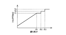
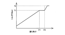
- FIG. 5 shows the relationship between the torque T input to the damper device 38 and the torsion angle ⁇ of the damper device 38.
- the horizontal axis indicates the twist angle ⁇
- the vertical axis indicates the torque T.
- a one-stage hysteresis torque T1 is realized in the torque limiter mechanism 68.
- the torque limiter mechanism 68 is disposed on the outer peripheral side of the disk plate 56, the working radius (rotation radius) r1 of the first friction material 88 is increased. Therefore, by adjusting the friction coefficient ⁇ 1 and the disc spring load W of the disc spring 82, a wide hysteresis torque from a small hysteresis torque to a large hysteresis torque can be obtained, so that the degree of freedom in design is greatly improved.
- the torque limiter mechanism 68 also functions as a hysteresis mechanism, that is, the torque limiter mechanism 68 also serves as the hysteresis mechanism, so that the torque limiter mechanism 68 capable of generating hysteresis torque with a simple structure is realized.
- the torque limiter mechanism 68 is provided with a hysteresis torque mechanism, the working radius (rotation radius) of the friction material is increased, and even a large hysteresis torque can be easily realized. Can do.
- conventionally it has been difficult to attenuate the resonance or engine starting torque, which is an input exceeding the maximum torque of the engine, by the hysteresis torque.
- the present embodiment it is possible to generate a hysteresis torque exceeding the maximum torque of the engine, so that it is possible to attenuate by the hysteresis torque at the time of resonance or engine start.
- the frictional force F1 generated on the friction surface between the pressure plate 80 and the first friction material 88 is changed to the friction surface between the lining plate 76 and the first friction material 88. Therefore, when the torque T is input to the damper device 38, the slip between the pressure plate 80 and the first friction material 88 occurs first, and the lining plate 76 and The first friction material 88 rotates integrally. At this time, a hysteresis torque T1 based on the frictional force between the pressure plate 80 and the first friction material 80 is generated. That is, the pressure plate 80 and the first friction material 88 constituting the torque limiter mechanism 68 function as a hysteresis mechanism.
- the torque limiter mechanism 68 functions as a normal torque limiter based on the frictional force generated on the friction surface between the lining plate 76 and the first friction material 88.
- the torque limiter mechanism 68 that also serves as the hysteresis mechanism can realize the torque limiter mechanism 68 that can generate the hysteresis torque with a simple structure.
- the torque limiter mechanism 68 is disposed on the outer peripheral side of the disk plate 56, the working radius (rotation radius) of the torque limiter mechanism 68 is increased, so that even a large hysteresis torque can be realized. it can. Further, by using a low friction material or the like, even a small hysteresis torque can be easily obtained. Furthermore, this configuration can be easily configured without adding the number of parts.
- the present configuration is different from the conventional configuration in that the friction coefficient on both sides of the friction material is different, the stopper hole 94 is formed in the friction material, and the protrusion 92 is formed in the pressure plate 80. Therefore, a wide hysteresis torque can be generated without making a large design change.
- the hysteresis of the torque limiter mechanism 64 can be added to realize a three-stage hysteresis torque.
- FIG. 6 is a cross-sectional view for explaining the structure of the torque limiter mechanism 102 provided in the damper device 100 according to another embodiment of the present invention, and corresponds to FIG. 3 in the above-described embodiment.
- the support plate 104 includes a pair of left and right disk-shaped first support plates 104a and a disk-shaped second support plate 104b. A space is formed between the first support plate 104a and the second support plate 104b by bending the inner periphery of the first support plate 104a in the axial direction.
- the disc spring 108, the pressure plate 106, the first friction material 110, the lining plate 76, and the second friction material 112 are accommodated in the space from the first support plate 104a toward the second support plate 104b.
- the torque limiter mechanism 102 corresponds to the vehicle torque limiter device of the present invention
- the first friction material 110 corresponds to the first friction material of the present invention
- the second friction material 112 corresponds to the second friction material of the present invention.
- the pressure plate 106 corresponds to the first cover plate of the present invention
- the second support plate 104b corresponds to the second cover plate of the present invention
- the disc spring 108 corresponds to the pressing member of the present invention. It corresponds to.
- the pressure plate 106 and the second support plate 104b are rotatably provided around the axis C, and the lining plate 76 is rotatable around the axis C with respect to the pressure plate 106 and the second support plate 104b. It is said that.
- a first friction material 110 is interposed between the pressure plate 106 and the lining plate 76.
- the first friction material 110 is configured to be slidable with the pressure plate 106 on the friction surface adjacent to the pressure plate 106, and to be slidable with the lining plate 76 on the friction surface adjacent to the lining plate 76. It is configured. That is, the first friction material 110 is not fixed to either the pressure plate 106 or the lining plate 76.
- the friction coefficient ⁇ 1 of the friction surface (sliding surface) between the pressure plate 106 and the first friction material 110 is the friction of the friction surface (sliding surface) between the lining plate 76 and the first friction material 110.
- the coefficient is smaller than ⁇ 2. That is, the frictional force F1 generated between the pressure plate 106 and the first friction material 110 is smaller than the friction material F2 generated between the lining plate 76 and the first friction material 110.
- a first stopper 116 (a first stopper 116) that defines an upper limit value of a slip amount (relative rotation amount) between the pressure plate 106 and the first friction material 110 is provided between the pressure plate 106 and the first friction material 110. 1 stopper) is provided.
- the first stopper 116 includes a cylindrical protrusion 118 protruding in the axial direction from the friction surface of the pressure plate 106 with the first friction material 110, and a perfect circular stopper hole 120 formed in the first friction material 110. It is configured.
- the protrusion 118 is accommodated in the stopper hole 120 and has a circumferential (rotational direction) backlash L1 (gap) for defining a slip amount (relative rotation) between the pressure plate 106 and the first friction material 110. Is formed.
- a second friction material 112 is formed between the inner peripheral portion of the second support plate 104b and the lining plate 76.
- the second friction material 112 is configured such that the friction surface on the side adjacent to the second support plate 104b is slidable with the second support plate 104b, and the lining plate also on the friction surface on the side adjacent to the lining plate 76.
- 76 is configured to be slidable. That is, the second friction material 112 is not fixed to any of the second support plate 104 b and the lining plate 76.
- the friction surface (sliding surface) between the second support plate 104b and the second friction material 112 is set to a friction coefficient ⁇ 1. That is, the friction coefficient ⁇ 1 of the friction surface (sliding surface) between the pressure plate 106 and the first friction material 110 is made equal.
- the friction coefficient ⁇ 3 of the friction surface (sliding surface) between the lining plate 76 and the second friction material 112 is the friction of the friction surface (sliding surface) between the lining plate 76 and the first friction material 110. The coefficient is larger than ⁇ 2.
- the friction coefficient ⁇ 1 of the friction surface (sliding surface) between the pressure plate 106 and the first friction material 110 and the friction surface (sliding surface) between the second support plate 104b and the second friction material 112 are obtained.
- the friction surface (sliding surface) between the lining plate 76 and the first friction material 110 is larger than the friction coefficient ⁇ 1
- the friction coefficient ⁇ 3 of the friction surface (sliding surface) is the largest ( ⁇ 3> ⁇ 2> ⁇ 1).
- the frictional force F1 generated between the pressure plate 106 and the first friction material 110 and the frictional force F1 generated between the second support plate 104b and the second friction material 112 are equal, and the lining plate 76 And the frictional force F2 generated between the first friction material 110 and the first friction material 110 is smaller. Further, the frictional force F2 generated between the lining plate 76 and the first friction material 110 is smaller than the frictional force F3 generated between the lining plate 76 and the second friction material 112 (F3> F2> F1). .
- a second stopper 122 (which defines a slippage amount (relative rotation amount) between the second support plate 104b and the second friction material 112 between the second support plate 104b and the second friction material 112).
- a second stopper is provided.
- the second stopper 122 includes a cylindrical protrusion 124 protruding in the axial direction from the friction surface of the second support plate 104b with the second friction material 112, and a perfect circular stopper hole 126 formed in the second friction material 112. It consists of and.
- the protrusion 124 is accommodated in the stopper hole 126, and a circumferential play L2 (gap) for defining a slip amount (relative rotation) between the second support plate 104b and the second friction material 112 is formed.
- the backlash L2 of the second stopper 122 is configured to be larger than the backlash L1 set by the first stopper 116.
- the protrusions 118 and 124 are formed in a cylindrical shape
- the stopper holes 120 and 126 are formed in a circular shape
- the diameter of the protrusion 124 is smaller than the protrusion 118
- the stopper hole 126 is the stopper hole. It is formed larger than 120.
- the slip amount defined by the first stopper 116 is smaller than the slip amount defined by the second stopper 122.
- FIG. 7 shows the relationship between the torque T transmitted to the damper device 100 and the torsion angle ⁇ .
- the torque T is input to the damper device 100 and the torsion angle ⁇ increases to reach the torsion angle ⁇ 1, the friction surface between the pressure plate 106 and the first friction material 110, the second support plate 104b, and the second friction First, slip occurs on the frictional surface with the material 112. This is because the frictional system number ⁇ 1 between the pressure plate 106 and the first friction material 110 and between the second support plate 104b and the second friction material 112 is the lowest.
- a hysteresis torque T1 expressed by the following expression (3) is generated.
- r1 represents the working radius (rotation radius) of the first friction material 110
- W represents the disc spring load of the disc spring 108.
- the torque limiter mechanism 102 two stages of hysteresis torques T1 and T2 are realized. That is, since the torque limiter mechanism 102 also serves as a hysteresis mechanism, the torque limiter mechanism 102 capable of generating hysteresis torque with a simple configuration is realized. Further, since the torque limiter mechanism 102 is disposed on the outer peripheral side of the disk plate 56, the radius (effective diameter) r1 of the first friction material 110 and the second friction material 112 is large.
- a wide hysteresis torque can be obtained from a small hysteresis torque to a large hysteresis torque, and the degree of freedom in design is greatly improved. Further, when a hysteresis mechanism 64 that generates a conventional two-stage hysteresis torque is added, a four-stage hysteresis torque can be realized.
- the torque limiter mechanism 102 when the torque T is input to the damper device 100, first, the friction surface between the pressure plate 106 and the first friction material 110, the second support plate 104b, Slip occurs on the friction surface between the two friction materials 112, and at this time, a first hysteresis torque T1 is generated.
- the first stopper 116 is locked, slippage occurs between the lining plate 76 and the first friction material 110, and at this time, a second hysteresis torque T2 is generated.
- the torque limiter mechanism 102 When the second stopper 122 is locked, the torque limiter mechanism 102 functions as a normal torque limiter based on the frictional force generated between the lining plate 76 and the second friction material 112. In this manner, the torque limiter mechanism 102 that can obtain a two-stage hysteresis torque can be realized.
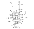
- FIG. 8 is a cross-sectional view of a torque limiter mechanism 152 (torque limiter device) of a damper device 150 according to still another embodiment of the present invention.
- the torque limiter mechanism 152 of the present embodiment is not continuously provided in the entire circumferential direction as in the above-described embodiment, and a plurality (four in this embodiment) are provided at equal angular intervals in the circumferential direction. It has been.
- the torque limiter mechanism 152 includes a lining plate 76, a pressure plate 156, a first friction material 158 interposed between the lining plate 76 and the pressure plate 156, a support plate 160, and a lining plate 76.
- the second friction member 162 interposed between the support plate 160 and the pressure plate 156 and the support plate 160 include a narrow pressure member 164 for narrowing the pressure from both ends in the axial direction.
- the torque limiter mechanism 152 corresponds to the vehicle torque limiter device of the present invention
- the pressure plate 156 corresponds to the first cover plate of the present invention
- the support plate 160 corresponds to the second cover plate of the present invention.
- the narrow pressure member 164 corresponds to the pressing member of the present invention
- the first friction material 158 corresponds to the first friction material of the present invention
- the second friction material 162 corresponds to the second friction material of the present invention. ing.
- the support plate 160 is formed in an annular plate shape, and further, a bolt hole 166 for bolt fastening (not shown) and a through hole 168 for penetrating the narrow pressure member 164 in the axial direction are formed.
- the support plate 160 and the pressure plate 156 are configured to be rotatable about the axis C, and the lining plate 76 is rotatable relative to the support plate 160 and the pressure plate 156 about the axis C.
- the friction surfaces between the first friction material 158 and the pressure plate 156 are configured to be slidable (relatively rotatable) with each other, and the friction surfaces between the first friction material 158 and the lining plate 76 are also slidable with each other. It is configured to be movable (relatively rotatable).
- the friction surface between the second friction material 162 and the support plate 160 is configured to be slidable (relatively rotatable) with each other, and the friction surface between the second friction material 162 and the lining plate 76 is These are slidable with respect to each other (relatively rotatable).
- the narrow pressure member 164 (pressing member) is made of spring steel, and has a first contact portion 170 whose inner peripheral end is in contact with the pressure plate 156, a second contact portion 172 in contact with the support plate 160, The first contact portion 170 and the second contact portion 172 include a connecting portion 174 that connects the outer peripheral end portions in the axial direction.
- the narrow pressure member 167 narrows (presses) the pressure plate 156 and the support plate 160 in the axial direction with a preset preload (cone spring load W).
- a first stopper 176 (a first stopper 176) that defines (limits) a slip amount (relative rotation amount) between the pressure plate 156 and the first friction material 158 is provided between the pressure plate 156 and the first friction material 158. 1 stopper) is provided.
- the first stopper 176 includes a cylindrical protrusion 178 that protrudes in the axial direction from the friction surface of the pressure plate 156 with the first friction material 158, and a stopper hole 180 formed in the first friction material 158. .
- the protrusion 178 is accommodated in the stopper hole 180, and a backlash L1 in the rotational direction for allowing a predetermined slip amount (relative rotation) between the pressure plate 156 and the first friction material 158 is formed. .
- a second stopper 182 (second rotation) for defining a slippage amount (relative rotation amount) between the support plate 160 and the second friction material 162 between the support plate 160 and the second friction material 162.
- the second stopper 182 includes a protrusion 184 that protrudes in the axial direction from the friction surface of the support plate 160 with the second friction material 162, and a stopper hole 186 formed in the second friction material 162.
- the protrusions 178 and the protrusions 184 have the same shape (outer diameter).
- the protrusion 184 is accommodated in the stopper hole 186, and a backlash (gap) L2 for defining a slip amount (relative rotation amount) between the support plate 160 and the second friction material 162 is formed.
- the play L2 is formed larger than the play L1 of the first stopper 176.
- FIG. 9 is a view as seen from an arrow A of the pressure limiter mechanism 152 of FIG. 8 when the pressure plate 156 and the first friction material 158 are viewed from the arrow A side of FIG. Note that FIG. 9 is a simplified diagram, and the scale and the like are not accurately described.
- first friction members 158 are arranged on the disc-shaped pressure plate 156 in the circumferential direction so as to be separated at equal angular intervals.
- the first friction material 158 located at the top is labeled with the first friction material 158a, and the first friction material 158 is rotated clockwise from the first friction material 158a.
- the first friction material d is denoted by a reference numeral.
- first stoppers 176a to 176d for defining a slip amount between the pressure plate 156 and the first friction material 158 are provided for the first friction materials 158a to 158d, respectively. Yes.
- the stopper hole 180 is also denoted by the same reference numerals as the first friction material 158 (180a to 180d).
- the disc spring load W generated by each narrow pressure member 164 is not changed.
- the protrusions 178 have the same shape, but the circumferential widths of the stopper holes 180 (180a to 180d) are different. Specifically, as shown in FIG. 9, in each stopper hole 180, the groove width Ha-1 of the stopper hole 180a is the smallest, and the groove width Hb-1 of the stopper hole 180b is larger than the groove width Ha-1 of the stopper hole 180a. The groove width Hc-1 of the stopper hole 180c is larger than the groove width Hb-1 of the stopper hole 180b, and the groove width Hd-1 of the stopper hole 180d is larger than the groove width Hc-1 of the stopper hole 180c. ing.
- FIG. 10 is a B arrow view of the support plate 160 and the second friction material 162 viewed from the arrow B side of FIG. 8 in the torque limiter mechanism 152 of FIG.
- FIG. 10 is a figure shown simply, the scale etc. are not described correctly and the outer peripheral part of the support plate 160 is abbreviate
- second friction members 162 are arranged on the disc-shaped support plate 160 separately at equal angular intervals in the circumferential direction.
- the uppermost second friction material 162 is labeled with the second friction material 162a, and the second friction material 162 is moved clockwise from the second friction material 162a to the second friction material 162b.
- second stoppers 182a to 182d for defining the sliding amount between the support plate 160 and the second friction material 162 are provided for the second friction materials 162a to 162d, respectively.
- the stopper holes 186 constituting the second stopper 182 are also given the same reference numerals as the second friction material 162 (186a to 186d).
- the protrusions 184 of the second stoppers 182a to 182d have the same shape as the protrusions 178 of the first stopper 176.
- the circumferential widths of the stopper holes 186a to 186d are different. Specifically, as shown in FIG. 10, in each stopper hole 186, the groove width Ha-2 of the stopper hole 186a is the smallest, and the groove width Hb-2 of the stopper hole 186b is the groove width Ha-2 of the stopper hole 186a.
- the groove width Hc-2 of the stopper hole 186c is larger than the groove width Hb-2 of the stopper hole 186b, and the groove width Hd-2 of the stopper hole 186d is larger than the groove width Hc-2 of the stopper hole 186c.
- the friction coefficient ⁇ of the friction surface between the pressure plate 156 and the first friction material 158a is ⁇ 1
- the friction coefficient of the friction surface between the lining plate 76 and the first friction material 158a is ⁇ 2
- the support plate 160 and the first friction material 158a is set to ⁇ 1
- the friction coefficient ⁇ of the friction surface between the two friction materials 162a is set to ⁇ 1
- the friction coefficient ⁇ of the friction surface between the lining plate 76 and the second friction surface 162a is set to ⁇ 3.
- the friction coefficient ⁇ of the friction surface between the pressure plate 156 and the first friction material 158b is ⁇ 1
- the friction coefficient ⁇ of the friction surface between the lining plate 76 and the first friction material 158b is ⁇ 4
- the support plate 160 The friction coefficient ⁇ of the friction surface between the second friction material 162b is set to ⁇ 1
- the friction coefficient ⁇ of the friction surface between the lining plate 76 and the second friction surface 162b is set to ⁇ 5.
- the friction coefficient ⁇ of the friction surface between the pressure plate 156 and the first friction material 158c is ⁇ 1
- the friction coefficient ⁇ of the friction surface between the lining plate 76 and the first friction material 158c is ⁇ 6
- the support plate 160 The friction coefficient ⁇ of the friction surface between the second friction material 162c is set to ⁇ 1
- the friction coefficient ⁇ of the friction surface between the lining plate 76 and the second friction surface 162c is set to ⁇ 7.
- the friction coefficient ⁇ of the friction surface between the pressure plate 156 and the first friction material 158d is ⁇ 1
- the friction coefficient ⁇ of the friction surface between the lining plate 76 and the first friction material 158d is ⁇ 8
- the support plate 160 The friction coefficient ⁇ of the friction surface between the second friction material 162d is set to ⁇ 1
- the friction coefficient ⁇ of the friction surface between the lining plate 76 and the second friction surface 162d is set to ⁇ 9.
- the friction coefficients ⁇ 1 to ⁇ 9 are set so as to have the relationship shown in the following equation (7).
- the frictional force F1 generated between the pressure plate 156 and the first friction material 158a the frictional force F1 generated between the support plate 160 and the second friction material 162a, the pressure plate 156 and the first friction material 158b.
- Friction force F1 generated between the support plate 160 and the second friction material 162b friction force F1 generated between the pressure plate 156 and the first friction material 158c
- the support plate Friction force F1 generated between 160 and the second friction material 162c friction force F1 generated between the pressure plate 156 and the first friction material 158d, and between the support plate 160 and the second friction material 162d.
- the generated frictional force F1 is the same and the smallest value. Further, the friction force F2 generated between the lining plate 76 and the first friction material 158a is larger than the friction force F1. In addition, the frictional force F3 generated between the lining plate 76 and the second friction surface 162a is larger than the frictional force F2. Further, the friction force F4 generated between the lining plate 76 and the first friction material 158b is larger than the friction force F3. Further, the frictional force F5 generated between the lining plate 76 and the second friction surface 162b is larger than the frictional force F4. Further, the friction force F6 generated between the lining plate 76 and the first friction material 158c is larger than the friction force F5.
- the frictional force F7 generated between the lining plate 76 and the second friction surface 162c is larger than the frictional force F6.
- the friction force F8 generated between the lining plate 76 and the first friction material 158d is larger than the friction force F7.
- the frictional force F9 generated between the lining plate 76 and the second friction surface 162d is larger than the frictional force F8.
- the friction material having a friction surface having a larger friction coefficient ⁇ set with the lining plate 76 is defined by each first stopper 176 and each second stopper 182.
- the amount of slippage to be performed is set to be large.
- FIG. 11 shows the relationship between the torque transmitted to the damper device 150 of this embodiment and the twist angle ⁇ .
- the torsion angle ⁇ increases in proportion thereto.
- the hysteresis torques T1 to T8 can be obtained in multiple stages.
- the friction coefficients ⁇ 1 to ⁇ 9 of the friction surfaces of the plurality of first friction materials 158a to 158d and the plurality of second friction materials 162a to 162d and the lining plate 76 are set. By making them different, it is possible to realize the torque limiter mechanism 152 that can obtain a multistage hysteresis torque with a simple structure.
- the stopper 200 shown in FIG. 12 includes, for example, a columnar protrusion 204 formed on the pressure plate 202 and a bottomed cylindrical stopper hole 208 formed on the friction material 206.
- a reinforcing member 210 made of a bottomed cylindrical metal is embedded in the wall surface of the stopper hole 208 so as to be fitted therein.
- the protrusion 204 contacts the reinforcing member 210 and does not directly contact the friction material resin constituting the friction material 206. Accordingly, a decrease in durability and damage due to the protrusions 204 coming into direct contact with the friction material resin are prevented.
- the shape of the reinforcing member 210 may be appropriately changed according to the shape of the stopper hole 208.
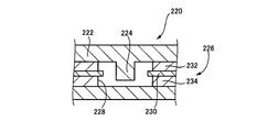
- the friction material 226 of this embodiment has a structure in which the first friction material 232 and the second friction material 234 are attached to the arc-shaped metal plate 230.
- the peripheral end of the metal plate 230 protrudes into the stopper hole 228.
- the 14 includes a columnar projection 246 formed on the pressure plate 242 and a cylindrical stopper hole 250 formed on the friction material 248.
- a cylindrical rubber member 252 is fitted on the outer peripheral surface of the protrusion 246.
- the stopper 240 is configured in this way, the protrusion 246 does not directly contact the friction material resin of the friction material 248, and the collision at the time of contact is alleviated.
- the twist characteristic is changed by the rubber member 252, and the change from the hysteresis torque T1 to the limiter torque T2 increases the twist angle ⁇ . It will change gently with. That is, it is possible to prevent the switching from the hysteresis torque T1 to the limiter torque T2 from changing sharply.
- the shape of the rubber member 252 may be changed as appropriate in accordance with the shape of the protrusion 246.
- the protrusions are all cylindrical, but are not necessarily limited thereto, and may be, for example, a square.
- the stopper hole can be freely changed according to the shape of the protrusion. That is, the shape of the protrusion and the stopper hole can be freely changed as long as the stopper is configured to regulate slip in the circumferential direction.
- the torque limiter mechanism 152 achieves eight stages of hysteresis torque, but can be freely changed by changing the number of friction materials and the like arranged in the circumferential direction.
- the damper mechanism is provided with the hysteresis mechanism 64.
- the torque limiter mechanism 68 can generate a hysteresis torque, the hysteresis mechanism can be omitted.
- the torque limiter mechanism 152 uses the plurality of first friction materials 158 and the plurality of second friction materials 162, but the first stopper 176 is provided only on the first friction material 158.
- a configuration in which the second stopper 182 is provided only on the second friction material 162 may be employed.
- the positions where the first friction material and the second friction material are inserted may be reversed left and right.
- Torque limiter mechanism (vehicle torque limiter device) 76: Lining plate 78b, 104b: Second support plate (second cover plate) 80, 106, 156: Pressure plate (cover plate, first cover plate) 82, 108: Belleville spring (pressing member) 88: First friction material (friction material) 90, 200, 220, 240: Stopper 110, 158: First friction material (first friction material) 112, 162: second friction material (second friction material) 116, 176: first stopper (first stopper) 122, 182: Second stopper (second stopper) 160: Support plate (second cover plate) 164: Narrow pressure member (pressing member)
Landscapes
- Engineering & Computer Science (AREA)
- General Engineering & Computer Science (AREA)
- Mechanical Engineering (AREA)
- Physics & Mathematics (AREA)
- Acoustics & Sound (AREA)
- Aviation & Aerospace Engineering (AREA)
- Transmission Devices (AREA)
- Mechanical Operated Clutches (AREA)
Abstract
L'invention concerne un dispositif limiteur de couple pour un véhicule ayant une structure simple capable de réaliser un couple d'hystérésis. Quand on applique un couple (T) à un amortisseur (38), il se crée un glissement entre un plateau de pression (80) et un premier élément de friction (88) et ensuite une plaque de revêtement (76) et le premier élément de friction (88) tournent ensemble, puisque la force de friction (F1) produite par les surfaces de frottement entre le plateau de pression (80) et le premier élément de friction (88) est inférieure à la force de friction (F2) produite par les surfaces de frottement entre la plaque de revêtement (76) et le premier élément de friction (88). À ce moment se produit un couple d'hystérésis (T1) reposant sur la force de friction entre le plateau de pression (80) et le premier élément de friction (88). En conséquence, on peut réaliser un mécanisme limiteur de couple (68) ayant une structure simple capable de produire un couple d'hystérésis, car le mécanisme limiteur de couple (68) fait fonction de mécanisme d'hystérésis.
Priority Applications (5)
| Application Number | Priority Date | Filing Date | Title |
|---|---|---|---|
| CN201180071488.1A CN103597230B (zh) | 2011-06-06 | 2011-06-06 | 车辆用转矩限制装置 |
| JP2013519249A JP5494891B2 (ja) | 2011-06-06 | 2011-06-06 | 車両用トルクリミッタ装置 |
| PCT/JP2011/062962 WO2012168997A1 (fr) | 2011-06-06 | 2011-06-06 | Dispositif limiteur de couple pour véhicule |
| US14/099,390 US20140094321A1 (en) | 2011-06-06 | 2013-12-06 | Torque-limiting device for vehicle |
| US15/047,321 US10208807B2 (en) | 2011-06-06 | 2016-02-18 | Torque-limiting device for vehicle |
Applications Claiming Priority (1)
| Application Number | Priority Date | Filing Date | Title |
|---|---|---|---|
| PCT/JP2011/062962 WO2012168997A1 (fr) | 2011-06-06 | 2011-06-06 | Dispositif limiteur de couple pour véhicule |
Related Child Applications (2)
| Application Number | Title | Priority Date | Filing Date |
|---|---|---|---|
| US14/099,390 Continuation-In-Part US20140094321A1 (en) | 2011-06-06 | 2013-12-06 | Torque-limiting device for vehicle |
| US14/099,390 Continuation US20140094321A1 (en) | 2011-06-06 | 2013-12-06 | Torque-limiting device for vehicle |
Publications (1)
| Publication Number | Publication Date |
|---|---|
| WO2012168997A1 true WO2012168997A1 (fr) | 2012-12-13 |
Family
ID=47295604
Family Applications (1)
| Application Number | Title | Priority Date | Filing Date |
|---|---|---|---|
| PCT/JP2011/062962 Ceased WO2012168997A1 (fr) | 2011-06-06 | 2011-06-06 | Dispositif limiteur de couple pour véhicule |
Country Status (4)
| Country | Link |
|---|---|
| US (2) | US20140094321A1 (fr) |
| JP (1) | JP5494891B2 (fr) |
| CN (1) | CN103597230B (fr) |
| WO (1) | WO2012168997A1 (fr) |
Cited By (6)
| Publication number | Priority date | Publication date | Assignee | Title |
|---|---|---|---|---|
| CN103899668A (zh) * | 2012-12-28 | 2014-07-02 | 上海三电贝洱汽车空调有限公司 | 压缩机及扭矩限定器 |
| JP2017015224A (ja) * | 2015-07-06 | 2017-01-19 | アイシン精機株式会社 | ダンパ装置 |
| JP2020523537A (ja) * | 2017-09-15 | 2020-08-06 | シェフラー テクノロジーズ アー・ゲー ウント コー. カー・ゲーSchaeffler Technologies AG & Co. KG | パワートレーンのためのトルクリミッタ |
| US20210102599A1 (en) * | 2019-10-02 | 2021-04-08 | Exedy Corporation | Torque limiter and power transmission device |
| US20210102598A1 (en) * | 2019-10-02 | 2021-04-08 | Exedy Corporation | Torque limiter and power transmission device |
| CN113039371A (zh) * | 2019-01-09 | 2021-06-25 | 舍弗勒技术股份两合公司 | 用于摩擦离合器的具有减震器单元的离合器片 |
Families Citing this family (8)
| Publication number | Priority date | Publication date | Assignee | Title |
|---|---|---|---|---|
| DE102017120530A1 (de) * | 2017-09-06 | 2019-03-07 | Schaeffler Technologies AG & Co. KG | Rutschkupplung mit einer Rotationsachse |
| DE102017121437A1 (de) * | 2017-09-15 | 2019-03-21 | Schaeffler Technologies AG & Co. KG | Drehmomentbegrenzer für einen Antriebsstrang |
| JP6666605B2 (ja) * | 2018-08-01 | 2020-03-18 | 株式会社エフ・シー・シー | トルクダンパー装置 |
| JP7267046B2 (ja) | 2019-03-15 | 2023-05-01 | 株式会社エクセディ | ダンパ装置 |
| JP7473420B2 (ja) * | 2020-08-20 | 2024-04-23 | 株式会社エクセディ | ダンパ装置 |
| CN112855798B (zh) | 2021-03-03 | 2023-01-03 | 舍弗勒技术股份两合公司 | 转矩限制装置、扭矩传递装置和车辆 |
| DE212021000582U1 (de) | 2021-09-06 | 2024-05-21 | Schaeffler Technologies AG & Co. KG | Drehmomentbegrenzungsmittel für ein Fahrzeug sowie Dämpfer für ein Fahrzeug |
| DE102022126302B3 (de) * | 2022-10-11 | 2024-01-25 | Schaeffler Technologies AG & Co. KG | Drehmomentbegrenzungsvorrichtung |
Citations (3)
| Publication number | Priority date | Publication date | Assignee | Title |
|---|---|---|---|---|
| JP2008304008A (ja) * | 2007-06-08 | 2008-12-18 | Aisin Seiki Co Ltd | トルク変動吸収装置 |
| JP2010223401A (ja) * | 2009-03-25 | 2010-10-07 | Aisin Seiki Co Ltd | トルク変動吸収装置 |
| JP2010236629A (ja) * | 2009-03-31 | 2010-10-21 | Toyota Motor Corp | トルクリミッタ機構 |
Family Cites Families (14)
| Publication number | Priority date | Publication date | Assignee | Title |
|---|---|---|---|---|
| US3775998A (en) * | 1972-04-14 | 1973-12-04 | Allied Steel Tractor Prod Inc | Safety clutch |
| BR8502761A (pt) * | 1984-06-12 | 1986-02-18 | Luk Lamellen & Kupplungsbau | Conjunto para a compensacao de choque de rotacao |
| US5154683A (en) * | 1991-11-19 | 1992-10-13 | Dana Corporation | Clutch having rotatable friction rings |
| JP4581576B2 (ja) | 2003-09-29 | 2010-11-17 | アイシン精機株式会社 | トルク変動吸収装置 |
| JP2005133859A (ja) * | 2003-10-31 | 2005-05-26 | Aisin Seiki Co Ltd | トルク変動吸収装置 |
| JP4747875B2 (ja) | 2006-02-16 | 2011-08-17 | アイシン精機株式会社 | トルク変動吸収装置 |
| JP4725348B2 (ja) * | 2006-02-16 | 2011-07-13 | アイシン精機株式会社 | トルク変動吸収装置 |
| JP4882642B2 (ja) * | 2006-09-29 | 2012-02-22 | アイシン精機株式会社 | トルク変動吸収装置 |
| JP4894467B2 (ja) * | 2006-11-08 | 2012-03-14 | アイシン精機株式会社 | トルク変動吸収装置 |
| JP5604906B2 (ja) | 2009-03-05 | 2014-10-15 | アイシン精機株式会社 | トルク変動吸収装置 |
| JP2010223294A (ja) * | 2009-03-23 | 2010-10-07 | Aisin Chem Co Ltd | 乾式摩擦材 |
| JP5691367B2 (ja) * | 2009-10-27 | 2015-04-01 | アイシン精機株式会社 | トルク変動吸収装置 |
| JP2012102755A (ja) * | 2010-11-05 | 2012-05-31 | Aisin Chemical Co Ltd | 車両用トルクリミッタ装置 |
| JP2016070323A (ja) * | 2014-09-29 | 2016-05-09 | アイシン精機株式会社 | 摩擦緩衝装置 |
-
2011
- 2011-06-06 WO PCT/JP2011/062962 patent/WO2012168997A1/fr not_active Ceased
- 2011-06-06 JP JP2013519249A patent/JP5494891B2/ja not_active Expired - Fee Related
- 2011-06-06 CN CN201180071488.1A patent/CN103597230B/zh not_active Expired - Fee Related
-
2013
- 2013-12-06 US US14/099,390 patent/US20140094321A1/en not_active Abandoned
-
2016
- 2016-02-18 US US15/047,321 patent/US10208807B2/en not_active Expired - Fee Related
Patent Citations (3)
| Publication number | Priority date | Publication date | Assignee | Title |
|---|---|---|---|---|
| JP2008304008A (ja) * | 2007-06-08 | 2008-12-18 | Aisin Seiki Co Ltd | トルク変動吸収装置 |
| JP2010223401A (ja) * | 2009-03-25 | 2010-10-07 | Aisin Seiki Co Ltd | トルク変動吸収装置 |
| JP2010236629A (ja) * | 2009-03-31 | 2010-10-21 | Toyota Motor Corp | トルクリミッタ機構 |
Cited By (9)
| Publication number | Priority date | Publication date | Assignee | Title |
|---|---|---|---|---|
| CN103899668A (zh) * | 2012-12-28 | 2014-07-02 | 上海三电贝洱汽车空调有限公司 | 压缩机及扭矩限定器 |
| JP2017015224A (ja) * | 2015-07-06 | 2017-01-19 | アイシン精機株式会社 | ダンパ装置 |
| JP2020523537A (ja) * | 2017-09-15 | 2020-08-06 | シェフラー テクノロジーズ アー・ゲー ウント コー. カー・ゲーSchaeffler Technologies AG & Co. KG | パワートレーンのためのトルクリミッタ |
| US11578765B2 (en) | 2017-09-15 | 2023-02-14 | Schaeffler Technologies AG & Co. KG | Torque limiter for a drive train |
| CN113039371A (zh) * | 2019-01-09 | 2021-06-25 | 舍弗勒技术股份两合公司 | 用于摩擦离合器的具有减震器单元的离合器片 |
| US20210102599A1 (en) * | 2019-10-02 | 2021-04-08 | Exedy Corporation | Torque limiter and power transmission device |
| US20210102598A1 (en) * | 2019-10-02 | 2021-04-08 | Exedy Corporation | Torque limiter and power transmission device |
| US11454298B2 (en) * | 2019-10-02 | 2022-09-27 | Exedy Corporation | Torque limiter and power transmission device |
| US11499603B2 (en) * | 2019-10-02 | 2022-11-15 | Exedy Corporation | Torque limiter and power transmission device |
Also Published As
| Publication number | Publication date |
|---|---|
| CN103597230B (zh) | 2016-01-06 |
| US20160160933A1 (en) | 2016-06-09 |
| US10208807B2 (en) | 2019-02-19 |
| JP5494891B2 (ja) | 2014-05-21 |
| CN103597230A (zh) | 2014-02-19 |
| US20140094321A1 (en) | 2014-04-03 |
| JPWO2012168997A1 (ja) | 2015-02-23 |
Similar Documents
| Publication | Publication Date | Title |
|---|---|---|
| JP5494891B2 (ja) | 車両用トルクリミッタ装置 | |
| JP5656949B2 (ja) | 車両のダンパ装置 | |
| JP5776673B2 (ja) | ハイブリッド車両の制御装置 | |
| CN103221714B (zh) | 车辆用减振装置 | |
| US8858345B2 (en) | Vehicle damper device | |
| US10138978B2 (en) | Vehicle damper device | |
| WO2014122744A1 (fr) | Dispositif de commande de véhicule hybride | |
| JP2012219883A (ja) | ハイブリッド車両のダンパ装置 | |
| JP5660213B2 (ja) | 車両用ダンパ装置 | |
| JP2014219061A (ja) | 車両用ダンパ装置 | |
| JP2013083317A (ja) | 車両用ダンパ装置 | |
| JP5859940B2 (ja) | 車両のダンパ装置 | |
| JP5998911B2 (ja) | ハイブリッド車両の制御装置 | |
| JP5673460B2 (ja) | 車両用ダンパ装置 | |
| JP2013087884A (ja) | 車両用ダンパ装置 | |
| JP2013050118A (ja) | 車両用トルクリミッタ | |
| JP2012233527A (ja) | 車両のトルクリミッタ装置 |
Legal Events
| Date | Code | Title | Description |
|---|---|---|---|
| 121 | Ep: the epo has been informed by wipo that ep was designated in this application |
Ref document number: 11867131 Country of ref document: EP Kind code of ref document: A1 |
|
| ENP | Entry into the national phase |
Ref document number: 2013519249 Country of ref document: JP Kind code of ref document: A |
|
| NENP | Non-entry into the national phase |
Ref country code: DE |
|
| 122 | Ep: pct application non-entry in european phase |
Ref document number: 11867131 Country of ref document: EP Kind code of ref document: A1 |