WO2012169036A1 - Appareil de soufflante et appareil d'oscillation laser à gaz - Google Patents
Appareil de soufflante et appareil d'oscillation laser à gaz Download PDFInfo
- Publication number
- WO2012169036A1 WO2012169036A1 PCT/JP2011/063225 JP2011063225W WO2012169036A1 WO 2012169036 A1 WO2012169036 A1 WO 2012169036A1 JP 2011063225 W JP2011063225 W JP 2011063225W WO 2012169036 A1 WO2012169036 A1 WO 2012169036A1
- Authority
- WO
- WIPO (PCT)
- Prior art keywords
- blower
- blower device
- rotation axis
- gravity
- support member
- Prior art date
- Legal status (The legal status is an assumption and is not a legal conclusion. Google has not performed a legal analysis and makes no representation as to the accuracy of the status listed.)
- Ceased
Links
Images




Classifications
-
- F—MECHANICAL ENGINEERING; LIGHTING; HEATING; WEAPONS; BLASTING
- F04—POSITIVE - DISPLACEMENT MACHINES FOR LIQUIDS; PUMPS FOR LIQUIDS OR ELASTIC FLUIDS
- F04D—NON-POSITIVE-DISPLACEMENT PUMPS
- F04D29/00—Details, component parts, or accessories
- F04D29/60—Mounting; Assembling; Disassembling
- F04D29/64—Mounting; Assembling; Disassembling of axial pumps
- F04D29/644—Mounting; Assembling; Disassembling of axial pumps especially adapted for elastic fluid pumps
-
- F—MECHANICAL ENGINEERING; LIGHTING; HEATING; WEAPONS; BLASTING
- F04—POSITIVE - DISPLACEMENT MACHINES FOR LIQUIDS; PUMPS FOR LIQUIDS OR ELASTIC FLUIDS
- F04D—NON-POSITIVE-DISPLACEMENT PUMPS
- F04D19/00—Axial-flow pumps
- F04D19/007—Axial-flow pumps multistage fans
-
- F—MECHANICAL ENGINEERING; LIGHTING; HEATING; WEAPONS; BLASTING
- F04—POSITIVE - DISPLACEMENT MACHINES FOR LIQUIDS; PUMPS FOR LIQUIDS OR ELASTIC FLUIDS
- F04D—NON-POSITIVE-DISPLACEMENT PUMPS
- F04D29/00—Details, component parts, or accessories
- F04D29/60—Mounting; Assembling; Disassembling
- F04D29/601—Mounting; Assembling; Disassembling specially adapted for elastic fluid pumps
-
- F—MECHANICAL ENGINEERING; LIGHTING; HEATING; WEAPONS; BLASTING
- F04—POSITIVE - DISPLACEMENT MACHINES FOR LIQUIDS; PUMPS FOR LIQUIDS OR ELASTIC FLUIDS
- F04D—NON-POSITIVE-DISPLACEMENT PUMPS
- F04D29/00—Details, component parts, or accessories
- F04D29/60—Mounting; Assembling; Disassembling
- F04D29/64—Mounting; Assembling; Disassembling of axial pumps
-
- F—MECHANICAL ENGINEERING; LIGHTING; HEATING; WEAPONS; BLASTING
- F04—POSITIVE - DISPLACEMENT MACHINES FOR LIQUIDS; PUMPS FOR LIQUIDS OR ELASTIC FLUIDS
- F04D—NON-POSITIVE-DISPLACEMENT PUMPS
- F04D29/00—Details, component parts, or accessories
- F04D29/66—Combating cavitation, whirls, noise, vibration or the like; Balancing
- F04D29/661—Combating cavitation, whirls, noise, vibration or the like; Balancing especially adapted for elastic fluid pumps
- F04D29/668—Combating cavitation, whirls, noise, vibration or the like; Balancing especially adapted for elastic fluid pumps damping or preventing mechanical vibrations
-
- H—ELECTRICITY
- H01—ELECTRIC ELEMENTS
- H01S—DEVICES USING THE PROCESS OF LIGHT AMPLIFICATION BY STIMULATED EMISSION OF RADIATION [LASER] TO AMPLIFY OR GENERATE LIGHT; DEVICES USING STIMULATED EMISSION OF ELECTROMAGNETIC RADIATION IN WAVE RANGES OTHER THAN OPTICAL
- H01S3/00—Lasers, i.e. devices using stimulated emission of electromagnetic radiation in the infrared, visible or ultraviolet wave range
- H01S3/02—Constructional details
- H01S3/03—Constructional details of gas laser discharge tubes
- H01S3/036—Means for obtaining or maintaining the desired gas pressure within the tube, e.g. by gettering, replenishing; Means for circulating the gas, e.g. for equalising the pressure within the tube
Definitions
- the present invention relates to a blower device for circulating gas or the like and a gas laser oscillation device equipped with the blower device, and in particular, to improve vibration proofing and airtightness at a mounting portion of the blower device.
- a conventional vibration generating device fixing mechanism such as a fan is for attaching a vibration generating device having a cylindrical elastic member having a groove on an outer peripheral portion and a fork-like portion fitted to a part of the groove provided on the elastic member.
- a support member see, for example, Patent Document 1.
- the conventional gas laser device is provided with support seats at four locations on the upper surface of the air blowing container, and the support seat is fastened to the support plate with bolts via an isolator so that the blower and the device main body are vibration-insulated. (For example, refer to Patent Document 2).
- the conventional fan device is first mounted by fitting rubber bushes through the notches into the mounting holes of the three bush mounting portions on the outer periphery of the fan casing.
- the second cylindrical portion inside each bush is fitted to each mounting boss on the fan mounting portion side.
- the fan device is mounted and fixed to the fan mounting portion by screwing mounting screws into the screw holes of the mounting bosses (see, for example, Patent Document 3).
- a blower device for circulating gas or the like is used in, for example, a gas laser oscillation device used for laser processing.
- Gas laser oscillators have increased in output for improving processing capability, and it is necessary to cool a large amount of laser gas. For this reason, the blower device is required to increase the rotation speed and the fan diameter.
- the rotational speed of the blower device has exceeded 10,000 rpm due to the adoption of a high torque motor.
- the vibration of the blower device is increased due to the high-speed rotation of the blower device and the increase in the fan diameter, and the vibration is transmitted to the casing of the gas laser oscillation device, causing vibration and noise of the gas laser oscillation device.
- the conventional vibration generator mounting structure supports a fan or the like via an elastic member, but the fan or the like is fixed to the center of the elastic member through the mounting member. For this reason, the vibration of the fan or the like is transmitted to the housing to which the fan or the like is attached via the attachment member, and there is a problem that the vibration isolation effect cannot be obtained sufficiently. In addition, since a large gap is formed so that the housing to which the fan or the like is attached and the attachment support member do not come into contact with each other during vibration, there is a problem that the airtightness at the attachment portion is lowered.
- the conventional laser apparatus attaches the blower and the apparatus body by fastening the support seat on the support plate with a bolt via an isolator.
- the conventional fan device fixes the fan device to the fan mounting portion by fitting a rubber bush to each mounting boss and screwing a mounting screw into the screw hole of each mounting boss. For this reason, the mounting boss and the mounting screw pass through the bush, and the vibration of the fan is transmitted to the fan mounting portion via the mounting screw, so that there is a problem that a sufficient anti-vibration effect cannot be obtained.
- the present invention has been made to solve the above-described problems, and provides a blower device having a high vibration proof property and a low-vibration / low-noise gas laser oscillation device provided with this blower device. With the goal.
- a blower device includes a motor, a blade attached to the rotation shaft of the motor, and a blade for flowing gas in the direction of the rotation shaft by the rotation of the motor, and the motor and the blade are accommodated, and a gas suction port side and a discharge port are accommodated.
- a blower casing having an opening on the mouth side, an elastic member that attaches a mounting portion that protrudes from the outer peripheral portion of the blower casing to a blower support member to be mounted that is disposed on the suction port side of the mounting portion, and suction of the mounting portion
- a flange portion provided on the entire outer periphery of the blower casing is provided on the mouth side.
- Three or more elastic members are arranged in the same plane substantially orthogonal to the rotation axis, include the rotation shaft inside a polygon having the elastic members as vertices, and both ends of the elastic members in the rotation axis direction.
- the part has an adhesive surface substantially orthogonal to the rotating shaft, and the attachment part is fixed to one adhesive surface, and the blower support member is fixed to the other adhesive surface.
- the flange portion is provided to face the blower support member through a gap smaller than the thickness of the elastic member in the rotation axis direction.
- the gas laser oscillation apparatus excites the laser gas by discharge to generate laser light, and circulates the laser gas in the blower device.
- the blower device includes a motor, a blade attached to the rotation shaft of the motor, and a blade that allows gas to flow in the direction of the rotation shaft by rotation of the motor.
- the motor and the blade are housed, and a gas suction port side and a discharge port.
- a blower casing having an opening on the side, an elastic member for attaching a mounting portion provided protruding from the outer peripheral portion of the blower casing to a blower support member to be mounted disposed on the suction port side of the mounting portion, and a suction port for the mounting portion And a flange portion provided on the entire outer peripheral portion of the blower casing.
- Three or more elastic members are arranged in the same plane substantially orthogonal to the rotation axis, include the rotation shaft inside a polygon having the elastic members as vertices, and both ends of the elastic members in the rotation axis direction.
- the part has an adhesive surface substantially orthogonal to the rotating shaft, and the attachment part is fixed to one adhesive surface, and the blower support member is fixed to the other adhesive surface.
- the flange portion is provided to face the blower support member through a gap smaller than the thickness of the elastic member in the rotation axis direction.
- the elastic members have adhesive surfaces that are substantially orthogonal to the rotational axis at both ends in the rotational axis direction, the attachment portion is attached to one adhesive surface, and the blower support member is bonded to the other adhesive surface. Since it is fixed, it is difficult for vibration of the blower device to be transmitted to the blower support member, and a blower device having a high vibration isolation effect can be obtained. And since the adhesion surface is substantially orthogonal to the rotation axis, radial vibration transmission can be effectively prevented.
- the flange portion supports the blower. It can prevent contacting a member. And this flange part can suppress gas leakage to the minimum.
- the blower device is provided, the elastic members of the blower device each have an adhesive surface substantially orthogonal to the rotational axis at both ends in the rotational axis direction, and the attachment portion is attached to one adhesive surface and the other adhesive Since the blower support members are respectively fixed to the surface by bonding, it is possible to effectively prevent the vibration of the blower device from being transmitted to the casing of the gas laser oscillation device, and to reduce the vibration and noise of the gas laser oscillation device. And since the adhesion surface is substantially orthogonal to the rotation axis, radial vibration transmission can be effectively prevented.
- the flange portion supports the blower. It can prevent contacting a member. And this flange part can suppress a gas leak to the minimum, and can circulate the laser gas smoothly in a housing
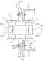
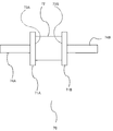
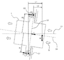
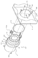
- FIG. 1 It is a perspective view which shows the structure of the blower apparatus by Embodiment 1 of this invention. It is sectional drawing which shows the state which attached the blower apparatus by Embodiment 1 of this invention to the blower support member of attachment object. It is an enlarged view of the vibration-proof rubber by Embodiment 1 of this invention. It is a figure which shows balance of the force which acts on a blower apparatus when it sees from a horizontal direction orthogonal to a rotating shaft at the time of attachment of the blower apparatus by Embodiment 1 of this invention.
- FIG. Embodiment 1 is a perspective view showing a configuration of a blower device 10 according to Embodiment 1 of the present invention
- FIG. 2 is a cross-sectional view of a state in which the blower device 10 is attached to a blower support member to be attached. This is the case seen from the direction.
- the blower device 10 is attached to both sides of the motor 1 such as a DC brushless motor and an induction motor, and the rotating shaft 2 of the motor 1 in the axial direction.
- the motor 1 such as a DC brushless motor and an induction motor
- a moving blade 3 as a flowing blade and a substantially cylindrical blower casing 4 which houses the motor 1 and the moving blade 3 inside and opens on the gas inlet side and the outlet side.
- the motor 1 is supported on the blower casing 4 via the stationary blade 5.
- the direction of arrow B in FIG. 2 is the direction in which the gas flows, and the right side of the blower casing 4 is the suction port side and the left side is the discharge port side. 1 and 2 indicate the axis of the rotating shaft 2.
- the shape of the blower casing 4 is substantially cylindrical. However, the shape is not limited to this, and the blower casing 4 may be, for example, a cylinder having a substantially square cross section.
- the moving blade 3 was provided in the axial direction both ends of the rotating shaft 2, you may provide only in any one side.
- the stationary blade 5 is provided as a supporting portion of the motor 1, a motor supporting structure other than the stationary blade may be used.
- the blower casing 4 has a projecting portion 410 provided so as to project outward on the entire circumference of the outer peripheral portion, and the projecting portion 410 has four mounting portions 41 so as to be positioned at equal intervals in the circumferential direction. Is provided. A mounting hole is formed in the mounting portion 41. On the suction port side of the attachment portion 41, the blower support member 6 to be attached is disposed so as to surround the blower casing 4 with a substantially circular opening 60.
- the attachment portion 41 is attached to the blower support member 6 via a rubber-like elastic member 7.
- a ring-shaped flange portion 42 that protrudes radially outward is provided on the entire outer periphery of the blower casing 4.
- the overhanging portion 410 and the flange portion 42 are integrally formed.
- the flange surface 42A on the suction port side of the flange portion 42 and the support surface 6A of the blower support member 6 face each other, and a gap X smaller than the thickness of the elastic member 7 in the rotation axis direction is formed around the entire attachment portion.
- the elastic member 7 is disposed at a position radially outside the flange portion 42.
- the present invention is not limited to this.
- the number of the elastic members 7 may be three or more, and the elastic members 7 may be arranged so as to include the rotating shaft 2 when assuming a polygon in which each elastic member 7 forms a vertex.
- the blower casing 4 is provided with the ring-shaped protruding portion 410 and the mounting portion 41 is provided with the mounting portion 41.
- the mounting portion 41 is the blower casing. 4 may be provided so as to protrude from the outer peripheral portion.
- the flange portion 42 is disposed radially inward of the attachment portion 41.
- the present invention is not limited to this.
- the configuration may be such that the attachment portion 41 is provided on the radially inner side of the overhang portion 410 and the flange portion 42 that protrudes from the overhang portion 410 toward the suction port side on the radially outer side.
- an anti-vibration rubber 70 is used as the elastic member 7.
- the anti-vibration rubber 70 has a general structure, and an enlarged view of the anti-vibration rubber 70 is shown in FIG.
- the anti-vibration rubber 70 is formed by arranging a rubber 72 between two parallel metal plate 71A, 71B, and bonding and fixing the metal plate 71A, 71B and the rubber part 72, and has adhesion surfaces 73A, 73B. .
- Fixing screws 74 ⁇ / b> A and 74 ⁇ / b> B are provided on the side opposite to the bonding surfaces 73 ⁇ / b> A and 73 ⁇ / b> B of both the metal plates 71 ⁇ / b> A and 71 ⁇ / b> B.
- One metal plate 71A of the anti-vibration rubber 70 is fixed to the attachment surface 41A on the suction port side of the attachment portion 41 by screws 74A and nuts 75A through the attachment holes of the attachment portion 41.
- the other metal plate 71B of the anti-vibration rubber 70 is provided on the support surface 6A of the blower support member 6 facing the attachment surface 41A via an attachment hole 6B provided in the blower support member 6 by screws 74B and nuts 75B. Fixed.
- the attachment surface 41A and the support surface 6A are substantially orthogonal to the rotation shaft 2, and the adhesion surfaces 73A and 73B of the metal plates 71A and 71B attached to these surfaces are also substantially orthogonal to the rotation shaft 2.
- the attachment portion 41 and the vibration isolating rubber 70, and the blower support member 6 and the vibration isolating rubber 70 are fixed by the adhesive force of the adhesive surfaces 73A and 73B of the rubber portion 72, respectively.
- the rubber portion 72 since no fixing pin or the like is inserted in the rubber portion 72, the inherent elastic characteristics of the rubber can be fully utilized.
- the anti-vibration rubber 70 provided with the metal plates 71A and 71B is used as the elastic member 7, but the elastic member 7 is not limited to this.
- the rubber member may be directly bonded to the attachment surface 41A and the support surface 6A.
- the vibration of the blower device due to the rotation of the moving blade will be described.
- the vibration of the blower device has a greater excitation force in the radial direction perpendicular to the rotation axis than in the rotation axis direction.
- Centrifugal force generated due to imbalance with respect to the rotation axis of the rotor constituting the motor is proportional to the square of the rotation speed. Therefore, due to the recent high speed rotation of the blower device exceeding 10,000 rpm, a large centrifugal force is generated and the radial excitation force is increasing more and more.
- vibration due to rotor imbalance is the same as the rotation frequency of the blower device and is low in frequency, so that it is difficult to prevent vibration.
- a rubber having a small spring constant with a high anti-vibration effect is suitable.
- vibration caused by variations in the magnetic poles and blades of the motor has a frequency as high as several times the number of rotations, and vibration isolation is relatively easy.
- rubber generally has a large difference in spring constant between the shear direction and the compression direction. For example, natural rubber rubber is about 1/7 times smaller in the shear direction than in the compression direction.
- the attachment part 41 of the blower casing 4 is attached to the blower support member 6 by adhesion with the rubber part 72.
- the bonding surfaces 73A and 73B are substantially orthogonal to the rotation axis 2.
- the rubber portion 72 acts in a shearing direction having a small spring constant against radial vibration generated in the blower device 10. For this reason, it is possible to effectively prevent a low-frequency and large excitation force from being transmitted to the blower support member 6 due to the unbalance of the rotor.
- the rubber portion 72 acts in the compression direction against vibration in the rotation axis direction generated in the blower device 10.
- the compression direction of the rubber part 72 has a high support force due to a large spring constant, and the axial displacement of the rubber part 72 due to the suction force of the blower device 10 and vibration in the rotation axis direction is small. For this reason, the change of the space
- the rubber compression direction has high rubber strength. For this reason, it can prevent that the rubber part 72 is damaged by the compressive load by the suction force of the powerful blower apparatus 10.
- the stress distribution is uniform, and there is no generation of high stress locally, so the durability is high.
- the rubber elastic member 7 is used.
- the material is not limited to this, and a material such as plastic may be used.
- a gap corresponding to the axial thickness of the antivibration rubber 70 is generated between the attachment portion 41 and the blower support member 6.
- a uniform gap can be formed around the entire circumference between the flange portion 42 and the blower support member 6, and the gap at the mounting portion can be reduced. For this reason, the gas leak in the attachment part of the blower apparatus 10 can be prevented. Further, as described above, the change in the axial interval between the mounting portion 41 and the blower support member 6 is small.
- the function and effect of disposing the anti-vibration rubber 70 on the suction port side of the mounting portion 41 will be described.
- the suction force due to the rotation of the moving blade 3 acts in a direction in which the bonding surfaces 73A and 73B of the anti-vibration rubber 70 are compressed. Therefore, it can prevent that an adhesion part peels.
- 4 and 5 are views showing a balance of forces acting on the blower device 10 when viewed from a horizontal direction orthogonal to the rotary shaft 2 when the blower device 10 is attached to the blower support member 6.
- 4 shows a case where the suction port side of the blower device 10 is facing downward
- FIG. 5 shows a case where the suction port side is facing upward.
- the anti-vibration rubber 70 is disposed so as to satisfy any of the following six conditional expressions.
- the dotted line C ⁇ b> 1 is a line indicating the horizontal direction
- the alternate long and short dash line C ⁇ b> 2 is a line orthogonal to the rotation axis 2.
- G1 Center of gravity of the anti-vibration rubber 70 disposed at the lowest position
- G2 Center of gravity
- L1 Anti-vibration rubber 70 disposed at the highest position
- L1 Distance in the horizontal direction from the center of G1 to the center of gravity of the blower device 10
- L2 Horizontal distance from G2 to the center of gravity of the blower device 10 (the suction port side is positive)
- M gravity acting on the blower device 10 (positive value)
- F Suction force of the blower device 10 (positive value)
- R1 Distance from axis 2A to G1 of rotation axis (downward is positive)
- R2 Distance from axis 2A to G2 of rotation axis (upward is positive)
- f1 Reaction force in the rotation axis direction from G1 (reaction force generated during G1 compression is positive)
- f2 Reaction force in the rotation axis direction from G2 (reaction force generated during G2 compression is positive)
- the vibration isolating rubber 70 As described above, by arranging the vibration isolating rubber 70 so as to satisfy any of the conditions (1) to (6), at least when the blower device 10 is operated, the adhesive surfaces 73A and 73B of the vibration isolating rubber 70 are provided. The tensile load does not work. For this reason, peeling can be reliably prevented. The most desirable is when the condition (2) is satisfied, and even if the blower device 10 is stopped, a tensile load is not applied to the bonding surfaces 73A and 73B. In the first embodiment, the load applied to two points of the anti-vibration rubber 70 arranged at the lowest position and the anti-vibration rubber 70 arranged at the highest position was examined. Because it is on the safe side, there is no problem of peeling.
- FIG. 6 is a perspective view showing a configuration of a blower device 10A according to Embodiment 2 of the present invention.
- FIG. 7 is a cross-sectional view of a state in which the blower device 10A is attached to a blower support member to be attached. It is sectional drawing seen from the direction.
- a rubber tube 8 that is a hollow elastic member is provided in the gap X between the flange portion 42 and the blower support member 6. ing.
- the rubber tube 8 has a slightly larger diameter than the gap X and is formed in an annular shape. By compressing and sandwiching the annular rubber tube 8 in the gap X, the gap can be closed and the airtightness at the mounting portion of the blower device 10A can be further enhanced.
- the hollow rubber tube 8 has the following effects as compared to the case of using solid rubber.
- the hollow rubber tube 8 has a smaller spring constant when compressed than when it is solid. Therefore, when the rubber tube 8 is compressed and sandwiched between the gaps, the tensile load acting on the adhesive surfaces 73A and 73B of the vibration isolating rubber 70 is small, and peeling can be prevented. Further, since the anti-vibration rubber 70 acts in the compression direction against the vibration in the rotation axis direction, the axial displacement of the anti-vibration rubber 70 is small. For this reason, the crushing allowance of the rubber tube 8 is reduced, so that no gap is generated due to vibration, and the airtightness is maintained.
- the hollow elastic member is made of rubber, but may be an elastic member made of plastic or the like.
- the same effect can be obtained by sandwiching a sponge instead of the hollow rubber tube 8. Since the sponge has bubbles inside and has a small spring constant when compressed, it does not have to be in the shape of a hollow tube, and only needs to have an outer diameter larger than the gap X.
- the gas laser oscillation device according to the third embodiment includes the blower device 10 according to the first embodiment.
- FIG. 8 is a perspective view schematically showing the configuration of the gas laser oscillation device 9
- FIG. 9 is a cross-sectional view schematically showing the configuration of the gas laser oscillation device 9.
- the gas laser oscillation device 9 includes an oscillation means 92 that oscillates laser light 91 in a casing 90, a blower device 10 that circulates laser gas in the direction of arrow E through the oscillation means 92, and a circulating laser gas in the middle. And a heat exchanger 93 for cooling.
- the oscillating means 92 includes a pair of vertically long electrodes 92A and 92B opposed to each other, and the laser gas is excited by discharge between the electrodes 92A and 92B, and laser light 91 is generated by the stimulated emission.
- a pair of reflecting means 94 for repeatedly reflecting and amplifying the laser light 91 is provided at both ends of the electrodes 92A and 92B.
- the laser light 91 is amplified while being repeatedly passed through the excited laser gas by the reflecting means 94. Is output.
- the heat exchanger 93 is attached to the housing 90, and a duct 95 for guiding laser gas is provided between the electrodes 92A and 92B and the heat exchanger 93. The laser gas is excited and the temperature rises.
- a blower device 10 is attached to the housing 90 via a blower support member 6 on the downstream side in the gas circulation direction of the heat exchanger 93, and the laser gas in the housing 90 is circulated.
- the configuration of the blower device 10 and the manner of attachment between the blower device 10 and the blower support member 6 are as described in the first embodiment, and the description of each component is omitted in FIGS. .
- the gas laser oscillation device 9 according to the third embodiment includes the blower device 10 according to the first embodiment, the gas laser oscillation device 9 has the same effect as the first embodiment. And it can prevent effectively that vibration of blower device 10 is transmitted to case 90 of gas laser oscillation device 9, and vibration and noise of gas laser oscillation device 9 can be reduced. In addition, since the gap between the attachment portions of the blower device 10 and the blower support member 6 can be reduced and gas leakage from the attachment portion can be suppressed, the laser gas can be circulated smoothly in the housing 90.
- Embodiment 3 although it was set as the structure provided with the blower apparatus 10 of Embodiment 1, it is good also as a structure provided with 10 A of blower apparatuses of the said Embodiment 2. FIG. In this case, gas leakage from the mounting portion of the blower device 10A can be further suppressed.
- the present invention can be widely applied to a blower device disposed in a gas laser oscillation device or the like, and can improve vibration proofing and airtightness at a mounting portion of the blower device.
Landscapes
- Engineering & Computer Science (AREA)
- Mechanical Engineering (AREA)
- General Engineering & Computer Science (AREA)
- Physics & Mathematics (AREA)
- Electromagnetism (AREA)
- Plasma & Fusion (AREA)
- Optics & Photonics (AREA)
- Structures Of Non-Positive Displacement Pumps (AREA)
- Lasers (AREA)
Abstract
Priority Applications (5)
| Application Number | Priority Date | Filing Date | Title |
|---|---|---|---|
| CN201180070960.XA CN103547809B (zh) | 2011-06-09 | 2011-06-09 | 鼓风机装置以及气体激光振荡装置 |
| PCT/JP2011/063225 WO2012169036A1 (fr) | 2011-06-09 | 2011-06-09 | Appareil de soufflante et appareil d'oscillation laser à gaz |
| JP2013519282A JP5538661B2 (ja) | 2011-06-09 | 2011-06-09 | ブロワ装置およびガスレーザ発振装置 |
| US14/114,666 US8942271B2 (en) | 2011-06-09 | 2011-06-09 | Blower apparatus and gas laser oscillation apparatus |
| DE112011105315.0T DE112011105315B4 (de) | 2011-06-09 | 2011-06-09 | Gebläsevorrichtung und Gaslaser-Oszillationsvorrichtung |
Applications Claiming Priority (1)
| Application Number | Priority Date | Filing Date | Title |
|---|---|---|---|
| PCT/JP2011/063225 WO2012169036A1 (fr) | 2011-06-09 | 2011-06-09 | Appareil de soufflante et appareil d'oscillation laser à gaz |
Publications (1)
| Publication Number | Publication Date |
|---|---|
| WO2012169036A1 true WO2012169036A1 (fr) | 2012-12-13 |
Family
ID=47295639
Family Applications (1)
| Application Number | Title | Priority Date | Filing Date |
|---|---|---|---|
| PCT/JP2011/063225 Ceased WO2012169036A1 (fr) | 2011-06-09 | 2011-06-09 | Appareil de soufflante et appareil d'oscillation laser à gaz |
Country Status (5)
| Country | Link |
|---|---|
| US (1) | US8942271B2 (fr) |
| JP (1) | JP5538661B2 (fr) |
| CN (1) | CN103547809B (fr) |
| DE (1) | DE112011105315B4 (fr) |
| WO (1) | WO2012169036A1 (fr) |
Cited By (2)
| Publication number | Priority date | Publication date | Assignee | Title |
|---|---|---|---|---|
| WO2015093076A1 (fr) * | 2013-12-17 | 2015-06-25 | 三菱電機株式会社 | Dispositif d'oscillation de laser à gaz de type à excitation orthogonale |
| US20160298652A1 (en) * | 2015-04-08 | 2016-10-13 | Ciena Corporation | Telecommunications system cooling fan incorporating a flange vibration isolator |
Families Citing this family (1)
| Publication number | Priority date | Publication date | Assignee | Title |
|---|---|---|---|---|
| JP6672054B2 (ja) * | 2016-04-19 | 2020-03-25 | アルバック・クライオ株式会社 | クライオポンプ、真空処理装置 |
Citations (2)
| Publication number | Priority date | Publication date | Assignee | Title |
|---|---|---|---|---|
| JPS62232983A (ja) * | 1986-04-03 | 1987-10-13 | Toshiba Corp | 気体レ−ザ装置 |
| JP2000027799A (ja) * | 1998-07-10 | 2000-01-25 | Toshiba Corp | ファン装置 |
Family Cites Families (17)
| Publication number | Priority date | Publication date | Assignee | Title |
|---|---|---|---|---|
| US2335508A (en) * | 1942-09-05 | 1943-11-30 | Binks Mfg Co | Fan |
| DE2215473C3 (de) * | 1972-03-29 | 1980-12-18 | Standard Elektrik Lorenz Ag, 7000 Stuttgart | Eigenschwingungsgedämpfter, geräuscharmer Radiallüfter |
| DE2714783A1 (de) * | 1977-04-02 | 1978-10-12 | Graefer Albrecht Dr Ing E H | Spaltschieber fuer ventilatoren |
| US4611327A (en) * | 1983-11-25 | 1986-09-09 | Amoco Corporation | Gas transport laser system |
| JPS60138046A (ja) | 1983-12-27 | 1985-07-22 | Hitachi Metals Ltd | トラツク用ステアリングナツクル |
| JPS60138046U (ja) * | 1984-02-24 | 1985-09-12 | 株式会社リコー | 振動発生機器固定機構 |
| DE3600124A1 (de) * | 1986-01-04 | 1987-07-16 | Fortuna Werke Maschf Ag | Geblaese zum umwaelzen grosser gasmengen, insbesondere fuer hochleistungs-laser |
| DE3600126A1 (de) * | 1986-01-04 | 1987-07-16 | Fortuna Werke Maschf Ag | Geblaese zum umwaelzen grosser gasmengen, insbesondere fuer hochleistungs-laser |
| US5030068A (en) * | 1989-09-18 | 1991-07-09 | Jacobs Paul G | Vibration and shock damping air blower |
| WO1994007033A1 (fr) * | 1992-09-23 | 1994-03-31 | United States Of America As Represented By The Secretary Of The Air Force | Soufflante turbomoleculaire |
| US5354182A (en) * | 1993-05-17 | 1994-10-11 | Vickers, Incorporated | Unitary electric-motor/hydraulic-pump assembly with noise reduction features |
| US6847671B1 (en) * | 2000-03-29 | 2005-01-25 | Lambda Physik Ag | Blower for gas laser |
| US6597719B1 (en) * | 2000-08-21 | 2003-07-22 | Komatsu Ltd. | Once through fan for gas laser apparatus and gas laser apparatus therewith |
| DE502004011172D1 (de) * | 2003-07-15 | 2010-07-01 | Ebm Papst St Georgen Gmbh & Co | Lüfteranordnung, und Verfahren zur Herstellung einer solchen |
| AU2007252223B2 (en) * | 2006-05-24 | 2009-04-23 | Resmed Motor Technologies Inc. | Compact low noise efficient blower for CPAP devices |
| JP5200880B2 (ja) * | 2008-11-19 | 2013-06-05 | ソニー株式会社 | 電子機器用送風装置及び電子機器 |
| CN102022386B (zh) * | 2009-09-21 | 2014-10-01 | 鸿富锦精密工业(深圳)有限公司 | 风扇固定装置 |
-
2011
- 2011-06-09 DE DE112011105315.0T patent/DE112011105315B4/de active Active
- 2011-06-09 CN CN201180070960.XA patent/CN103547809B/zh active Active
- 2011-06-09 US US14/114,666 patent/US8942271B2/en active Active
- 2011-06-09 JP JP2013519282A patent/JP5538661B2/ja active Active
- 2011-06-09 WO PCT/JP2011/063225 patent/WO2012169036A1/fr not_active Ceased
Patent Citations (2)
| Publication number | Priority date | Publication date | Assignee | Title |
|---|---|---|---|---|
| JPS62232983A (ja) * | 1986-04-03 | 1987-10-13 | Toshiba Corp | 気体レ−ザ装置 |
| JP2000027799A (ja) * | 1998-07-10 | 2000-01-25 | Toshiba Corp | ファン装置 |
Cited By (8)
| Publication number | Priority date | Publication date | Assignee | Title |
|---|---|---|---|---|
| WO2015093076A1 (fr) * | 2013-12-17 | 2015-06-25 | 三菱電機株式会社 | Dispositif d'oscillation de laser à gaz de type à excitation orthogonale |
| CN105745796A (zh) * | 2013-12-17 | 2016-07-06 | 三菱电机株式会社 | 正交激励型气体激光振荡装置 |
| JPWO2015093076A1 (ja) * | 2013-12-17 | 2017-03-16 | 三菱電機株式会社 | 直交励起型ガスレーザ発振装置 |
| US9634456B2 (en) | 2013-12-17 | 2017-04-25 | Mitsubishi Electric Cororation | Gas laser oscillation apparatus of orthogonal excitation type |
| KR101823806B1 (ko) * | 2013-12-17 | 2018-01-30 | 미쓰비시덴키 가부시키가이샤 | 직교 여기형 가스 레이저 발진 장치 |
| CN105745796B (zh) * | 2013-12-17 | 2018-11-06 | 三菱电机株式会社 | 正交激励型气体激光振荡装置 |
| US20160298652A1 (en) * | 2015-04-08 | 2016-10-13 | Ciena Corporation | Telecommunications system cooling fan incorporating a flange vibration isolator |
| US9759235B2 (en) * | 2015-04-08 | 2017-09-12 | Ciena Corporation | Telecommunications system cooling fan incorporating a flange vibration isolator |
Also Published As
| Publication number | Publication date |
|---|---|
| JP5538661B2 (ja) | 2014-07-02 |
| US20140086270A1 (en) | 2014-03-27 |
| DE112011105315T5 (de) | 2014-02-27 |
| CN103547809B (zh) | 2016-01-20 |
| CN103547809A (zh) | 2014-01-29 |
| DE112011105315B4 (de) | 2016-12-22 |
| JPWO2012169036A1 (ja) | 2015-02-23 |
| US8942271B2 (en) | 2015-01-27 |
Similar Documents
| Publication | Publication Date | Title |
|---|---|---|
| AU2021201908B2 (en) | Fan motor | |
| EP1623122B8 (fr) | Ensemble ventilateur de refroidissement de moteur automobile | |
| CN103629146B (zh) | 真空泵 | |
| JPH0771390A (ja) | ノイズ低減特性を備えた電動モータ/油圧ポンプアセンブリユニット | |
| BR112016012249B1 (pt) | Compressor rotativo | |
| JP2013177826A (ja) | 電動圧縮機 | |
| JP5538661B2 (ja) | ブロワ装置およびガスレーザ発振装置 | |
| KR102147730B1 (ko) | 송풍량을 증대하며 진동소음을 최소화한 bmc모터를 이용한 블로어 | |
| JP2009293523A (ja) | 電動圧縮機 | |
| KR20080024486A (ko) | 방사형 압축기 | |
| KR101833146B1 (ko) | 진동 저감을 위한 모터 고정브라켓 | |
| JP7678012B2 (ja) | 送風機 | |
| KR101354055B1 (ko) | 진동 저감을 위한 모터 고정브라켓 | |
| JP2020067037A (ja) | 圧縮機 | |
| JP2016138511A (ja) | 電動送風機およびそれを用いた電気掃除機 | |
| JP2013079620A (ja) | スクリュ圧縮機 | |
| CN222735932U (zh) | 用于转轴的支撑件、电机、电驱系统以及车辆 | |
| JP2000045987A (ja) | 軸流ファン | |
| JP2005315236A (ja) | 送風機 | |
| CN118367708B (zh) | 电机、电驱系统以及车辆 | |
| CN115370585B (zh) | 一种卧式泵 | |
| CN219802014U (zh) | 一种带防护结构的振动电机 | |
| JP2008002420A (ja) | 流体機械 | |
| JP2005299433A (ja) | 送風ユニット | |
| RU189522U1 (ru) | Герметичный химический вертикальный электронасосный агрегат |
Legal Events
| Date | Code | Title | Description |
|---|---|---|---|
| 121 | Ep: the epo has been informed by wipo that ep was designated in this application |
Ref document number: 11867457 Country of ref document: EP Kind code of ref document: A1 |
|
| ENP | Entry into the national phase |
Ref document number: 2013519282 Country of ref document: JP Kind code of ref document: A |
|
| WWE | Wipo information: entry into national phase |
Ref document number: 14114666 Country of ref document: US |
|
| WWE | Wipo information: entry into national phase |
Ref document number: 1120111053150 Country of ref document: DE Ref document number: 112011105315 Country of ref document: DE |
|
| 122 | Ep: pct application non-entry in european phase |
Ref document number: 11867457 Country of ref document: EP Kind code of ref document: A1 |